- Table of Contents
- Related Documents
-
| Title | Size | Download |
|---|---|---|
| 01-Text | 570.79 KB |
Contents
About the LSWM116FC interface module
Installing and removing an interface module
Installing an interface module
About the LSWM116FC interface module
Important information
The LSWM116FC interface module is applicable to multiple H3C switch models. For the interface module compatibility with switches, contact H3C Support or marketing staff.
The restrictions and guidelines for using the LSWM116FC interface module vary by device model. For more information, see the installation guide or hardware reference for the device.
Front panel
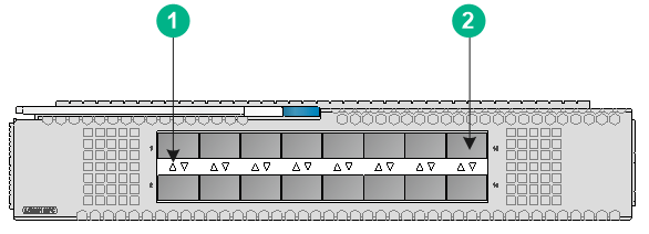
The LSWM116FC interface module provides 16 SFP28 ports and supports fibre channel (FC) transceiver modules of various data rates.
Figure 1 Front panel
|
(1) SFP28 port LED |
(2) SFP28 port |
Ports
|
IMPORTANT: As a best practice, use H3C transceiver modules and cables for the interface module. |
The ports on the interface module can be used as Ethernet interfaces or FC interfaces. You can use the port-type command in Layer 2 Ethernet interface view to change the interface type between Ethernet and FC. For more information about configuring the interface type, see the FC and FCoE configuration guide for the device.
A port on the interface module supports 8G/16G/32G FC transceiver modules when configured as an FC interface. For the 8G/16G/32G FC transceiver modules available for the ports, see the installation guide or hardware reference for the device, or contact H3C Support or marketing staff. The data rate changing method for FC interfaces varies by device model. For more information, see the FC and FCoE configuration guide for the device.
The transceiver modules and cables available for a port on the interface module depend on the device model when the port is configured as an Ethernet interface. For example, if the interface module is installed on an S6800 switch, an Ethernet interface on the module supports only 10G SFP+ transceiver modules and cables and 1G SFP transceiver modules. For the most-recent list of available transceiver modules and cables, see the installation guide or hardware reference for the device, or contact H3C Support or marketing staff.
For more information about H3C transceiver modules and cables, see H3C Transceiver Modules User Guide at www.h3c.com.
LEDs
Important information
The indications of the LEDs on the LSWM116FC interface module vary by device model. For more information, see the installation guide or hardware reference for the device.
SFP28 port LEDs
Table 1 describes SFP28 port LEDs.
Table 1 SFP28 port LED description
|
LED status |
Description |
|
Steady green |
A link is present on the port and the port is operating at the maximum speed. |
|
Flashing green |
The port is sending or receiving data at the maximum speed. |
|
Steady yellow |
A link is present on the port and the port is operating at a speed lower than the maximum speed. |
|
Flashing yellow |
The port is sending or receiving data at a speed lower than the maximum speed. |
|
Off |
No link is present on the port. |
Installing and removing an interface module
|
|
CAUTION: · Before you install or remove an interface module, wear an ESD wrist strap and make sure the strap makes good skin contact and is reliably grounded. · To avoid device damage, do not use excessive force when you install or remove an interface module. |
Installing an interface module
Before you install an interface module, remove the filler panel (if any) from the target slot. Keep the removed filler panel secure for future use.
To install an interface module:
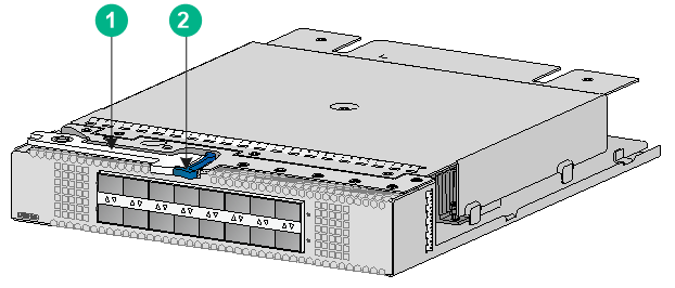
1. Unpack the interface module.
Figure 2 LSWM116FC interface module
|
(1) Ejector lever |
(2) Latch |
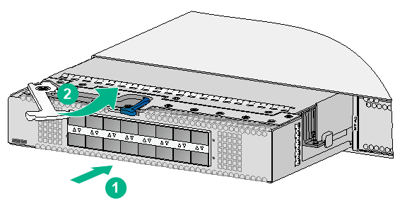
2. Press the latch on the interface module to release the ejector lever.
3. As shown by callout 1 in Figure 3, insert the interface module slowly into the slot along the guide rails.
4. Rotate inward the ejector lever as shown by callout 2 in Figure 3 until the latch locks the ejector lever in place.
Figure 3 Installing an LSWM116FC interface module
Removing an interface module
|
|
CAUTION: · Before you remove an interface module, remove the cable from it to avoid cable damage. · After removing an interface module, if no new interface module is to be installed, install the filler panel as soon as possible to prevent dust and ensure good ventilation in the device. |
To remove an interface module:
1. Prepare an anti-static bag.
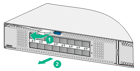
2. Press the latch to release the ejector lever
3. Rotate outward the ejector lever as shown by callout 1 in Figure 4.
4. Pull out the interface module slowly out of the interface module slot, as shown by callout 2 in Figure 4.
5. Place the removed interface module into an anti-static bag.
Figure 4 Removing an LSWM116FC interface module
Installing and removing transceiver modules and cables
For information about installing and removing transceiver modules and cables, see H3C Transceiver Modules and Network Cables Installation Guide at www.h3c.com.
Verifying the installation
After the installation is complete, identify whether the interface module is operating correctly.
If the interface module fails to operate correctly, perform the following steps:
1. Reinstall it following the installation procedures described in this document.
2. If the issue persists, contact H3C Support.
