- Table of Contents
-
- 10-High Availability Configuration Guide
- 00-Preface
- 01-Ethernet OAM configuration
- 02-CFD configuration
- 03-DLDP configuration
- 04-RRPP configuration
- 05-ERPS configuration
- 06-Smart Link configuration
- 07-Monitor Link configuration
- 08-VRRP configuration
- 09-BFD configuration
- 10-Track configuration
- 11-Process placement configuration
- Related Documents
-
| Title | Size | Download |
|---|---|---|
| 09-BFD configuration | 144.83 KB |
Contents
BFD session establishment and termination
Single-hop detection and multihop detection
Restrictions and guidelines: BFD configuration
Configuring control packet mode
Configuring control packet mode for single-hop detection
Configuring control packet mode for multihop detection
Configuring BFD session flapping suppression
Enabling SNMP notifications for BFD
Display and maintenance commands for BFD
Restrictions and guidelines: SBFD configuration
Configuring the initiator for LDP LSP detection
Configuring BFD
About BFD
Bidirectional forwarding detection (BFD) provides a general-purpose, standard, medium- and protocol-independent fast failure detection mechanism. It can detect and monitor the connectivity of links in IP to detect communication failures quickly so that measures can be taken to ensure service continuity and enhance network availability.
BFD can uniformly and quickly detect the failures of the bidirectional forwarding paths between two devices for upper-layer protocols such as routing protocols. The hello mechanism used by upper-layer protocols needs seconds to detect a link failure, while BFD can provide detection measured in milliseconds.
BFD session establishment and termination
BFD does not provide any neighbor discovery mechanisms. The upper protocol notifies BFD of the routers to which it needs to establish sessions. After establishing a neighborship, the upper protocol notifies BFD of the neighbor information, including destination and source addresses. BFD uses the information to establish a BFD session.
When BFD detects a link failure, it performs the following tasks:
1. BFD clears the neighbor session and notifies the protocol of the failure.
2. The protocol terminates the neighborship on the link.
3. If a backup link is available, the protocol will use it for communication.
Single-hop detection and multihop detection
BFD can be used for single-hop and multihop detections.
· Single-hop detection—Detects the IP connectivity between two directly connected systems.
· Multihop detection—Detects any of the paths between two systems. These paths have multiple hops, and might overlap.
BFD session modes
BFD sessions use echo packets and control packets.
Echo packet mode
Echo packets are encapsulated into UDP packets with port number 3785.
The local end of the link sends echo packets to establish BFD sessions and monitor link status. The peer end does not establish BFD sessions and only forwards the packets back to the originating end. If the local end does not receive echo packets from the peer end within the detection time, it considers the session to be down.
In echo packet mode, BFD supports multihop detection only for MPLS TE tunnel scenarios. Both BFD sessions for single-hop detection and BFD sessions for multihop detection are independent of the operating mode.
Control packet mode
Control packets are encapsulated into UDP packets with port number 3784 for single-hop detection or port number 4784 for multihop detection.
Both ends of the link exchange BFD control packets to monitor link status.
Before a BFD session is established, BFD has two operating modes—active and passive.
· Active mode—BFD actively sends BFD control packets regardless of whether any BFD control packet is received from the peer.
· Passive mode—BFD does not send control packets until a BFD control packet is received from the peer.
At least one end must operate in active mode for a BFD session to be established.
After a BFD session is established, the two ends can operate in the following BFD operating modes:
· Asynchronous mode—The device periodically sends BFD control packets. The device considers that the session is down if it does not receive any BFD control packets within a specific interval.
· Demand mode—The device periodically sends BFD control packets. If the peer end is operating in Asynchronous mode (default), the peer end stops sending BFD control packets. If the peer end is operating in Demand mode, both ends stop sending BFD control packets. When the connectivity to another system needs to be verified explicitly, a system sends several BFD control packets with the Poll (P) bit set at the negotiated transmit interval. If no response is received within the detection interval, the session is considered down. If the connectivity is found to be up, no more BFD control packets are sent until the next command is issued.
Supported features
|
Features |
Reference |
|
Static routing IS-IS OSPF RIP BGP IP fast reroute (FRR) |
Layer 3—IP Routing Configuration Guide |
|
IPv6 static routing OSPFv3 |
Layer 3—IP Routing Configuration Guide |
|
PIM |
IP Multicast Configuration Guide |
|
RSVP MPLS MPLS L3VPN MPLS OAM |
MPLS Configuration Guide |
|
Track |
"Configuring Track" |
|
Ethernet link aggregation |
Layer 2—LAN Switching Configuration Guide |
Protocols and standards
· RFC 5880, Bidirectional Forwarding Detection (BFD)
· RFC 5881, Bidirectional Forwarding Detection (BFD) for IPv4 and IPv6 (Single Hop)
· RFC 5882, Generic Application of Bidirectional Forwarding Detection (BFD)
· RFC 5883, Bidirectional Forwarding Detection (BFD) for Multihop Paths
· RFC 5884, Bidirectional Forwarding Detection (BFD) for MPLS Label Switched Paths (LSPs)
· RFC 5885, Bidirectional Forwarding Detection (BFD) for the Pseudowire Virtual Circuit Connectivity Verification (VCCV)
· RFC 7130, Bidirectional Forwarding Detection (BFD) on Link Aggregation Group (LAG) Interfaces
Restrictions and guidelines: BFD configuration
· By default, the device runs BFD version 1 and is compatible with BFD version 0. You cannot change the BFD version to 0 through commands. When the peer device runs BFD version 0, the local device automatically switches to BFD version 0.
· After a BFD session is established, the two ends negotiate BFD parameters, including minimum sending interval, minimum receiving interval, initialization mode, and packet authentication, by exchanging negotiation packets. They use the negotiated parameters without affecting the session status.
· In an IRF fabric, if the detection time is smaller than the IRF link down report delay, the BFD session might flap. To prevent this problem, set the IRF link down report delay to be smaller than the detection time. For information about setting the IRF link down report delay, see IRF configuration in Virtual Technologies Configuration Guide.
Configuring echo packet mode
Restrictions and guidelines
To avoid echo packet loss, do not configure the echo packet mode on a device with uRPF enabled. For more information about uRPF, see Security Configuration Guide.
Procedure
1. Enter system view.
system-view
2. Configure the source IP address of echo packets.
¡ Configure the source IP address of echo packets.
bfd echo-source-ip ip-address
By default, no source IPv4 address is configured for echo packets.
As a best practice, do not configure the source IPv4 address to be on the same network segment as any local interface's IPv4 address. If you configure such a source IPv4 address, a large number of ICMP redirect packets might be sent from the peer, resulting in link congestion.
¡ Configure the source IPv6 address of echo packets.
bfd echo-source-ipv6 ipv6-address
By default, no source IPv6 address is configured for echo packets.
The source IPv6 address of echo packets can only be a global unicast address.
3. (Optional.) Set the echo packet mode parameters.
a. Enter interface view.
interface interface-type interface-number
b. Set the minimum interval for receiving BFD echo packets.
bfd min-echo-receive-interval interval
The default setting is 400 milliseconds.
c. Set the detection time multiplier.
bfd detect-multiplier value
The default setting is 5.
Configuring control packet mode
Restrictions and guidelines
After an upper-layer protocol is configured to support BFD, the device automatically creates BFD sessions in control packet mode. You do not need to perform this task.
BFD version 0 does not support the following commands:
· bfd session init-mode.
· bfd authentication-mode.
· bfd demand enable.
· bfd echo enable.
Configuring control packet mode for single-hop detection
1. Enter system view.
system-view
2. Specify the mode for establishing a BFD session.
bfd session init-mode { active | passive }
By default, active is specified.
3. Enter interface view.
interface interface-type interface-number
4. (Optional.) Configure the authentication mode for single-hop control packets.
bfd authentication-mode { hmac-md5 | hmac-mmd5 | hmac-msha1 | hmac-sha1 | m-md5 | m-sha1 | md5 | sha1 | simple } key-id { cipher cipher-string | plain plain-string }
By default, single-hop BFD packets are not authenticated.
5. Enable the Demand BFD session mode.
bfd demand enable
By default, the BFD session is in Asynchronous mode.
6. (Optional.) Enable the echo packet mode.
bfd echo [ receive | send ] enable
By default, the echo packet mode is disabled.
Configure this command for BFD sessions in which control packets are sent. When you enable the echo packet mode for such a session in up state, BFD periodically sends echo packets to detect link connectivity and decrease control packet receive rate.
7. Set the minimum interval for transmitting and receiving single-hop BFD control packets.
¡ Set the minimum interval for transmitting single-hop BFD control packets.
bfd min-transmit-interval interval
The default setting is 400 milliseconds.
¡ Set the minimum interval for receiving single-hop BFD control packets.
bfd min-receive-interval interval
The default setting is 400 milliseconds.
8. Set the single-hop detection time multiplier.
bfd detect-multiplier value
The default setting is 5.
9. (Optional.) Create a BFD session for detecting the local interface state.
bfd detect-interface source-ip ip-address [ discriminator local local-value remote remote-value ] [ template template-name ]
By default, no BFD session is created for detecting the local interface state.
This command implements fast collaboration between interface state and BFD session state. When BFD detects a link fault, it sets the link layer protocol state to DOWN(BFD). This behavior helps applications relying on the link layer protocol state achieve fast convergence.
10. (Optional.) Configure the timer that delays reporting the first BFD session establishment failure to the data link layer.
bfd detect-interface first-fail-timer seconds
By default, the first BFD session establishment failure is not reported to the data link layer.
11. (Optional.) Enable special processing for BFD sessions.
bfd detect-interface special-processing [ admin-down | authentication-change | session-up ] *
By default, all types of special processing for BFD sessions are disabled.
Configuring control packet mode for multihop detection
1. Enter system view.
system-view
2. Specify the mode for establishing a BFD session.
bfd session init-mode { active | passive }
By default, active is specified.
3. (Optional.) Configure the authentication mode for multihop BFD control packets.
bfd multi-hop authentication-mode { hmac-md5 | hmac-mmd5 | hmac-msha1 | hmac-sha1 | m-md5 | m-sha1 | md5 | sha1 | simple } key-id { cipher cipher-string | plain plain-string }
By default, no authentication is performed.
4. Configure the destination port number for multihop BFD control packets.
bfd multi-hop destination-port port-number
The default setting is 4784.
5. Set the multihop detection time multiplier.
bfd multi-hop detect-multiplier value
The default setting is 5.
6. Set the minimum interval for transmitting and receiving multihop BFD control packets.
¡ Set the minimum interval for transmitting multihop BFD control packets.
bfd multi-hop min-transmit-interval interval
The default setting is 400 milliseconds.
¡ Set the minimum interval for receiving multihop BFD control packets.
bfd multi-hop min-receive-interval interval
The default setting is 400 milliseconds.
Configuring BFD session flapping suppression
About BFD session flapping suppression
When BFD detects a link failure, it tears down the BFD session and notifies the upper-layer protocol of the failure. When the upper-layer protocol re-establishes a neighbor relationship, the BFD session comes up again. BFD session flaps occur when a link fails and recovers repeatedly, which consumes significant system resources and causes network instability.
This feature allows you to suppress BFD session flapping by using the initial-interval, secondary-interval, and maximum-interval arguments.
· A BFD session is suppressed within the specified interval. The suppression time does not exceed the maximum-interval.
· After a BFD session goes down for the second time, it cannot be re-established within the initial-interval.
· After a BFD session goes down for the third time, it cannot be re-established within the secondary-interval.
· After a BFD session goes down for the fourth time and at any later time, the following rules apply:
¡ If secondary-interval × 2n-3 is smaller than or equal to the maximum-interval, the BFD session cannot be re-established within the secondary-interval × 2n-3.
¡ If secondary-interval × 2n-3 is greater than the maximum-interval, the BFD session cannot be re-established within the maximum-interval.
The letter n, starting from 4, is the number of times the BFD session flaps.
Procedure
1. Enter system view.
system-view
2. Configure BFD session flapping suppression.
bfd dampening [ maximum maximum-interval initial initial-interval secondary secondary-interval ]
By default, BFD sessions are not suppressed.
The values for the initial-interval and secondary-interval arguments cannot be greater than the value for the maximum-interval argument.
Configuring a BFD template
About configuring a BFD template
Perform this task to specify BFD parameters in a template for sessions without next hops. You can configure BFD parameters for LSPs and PWs through a BFD template.
Procedure
1. Enter system view.
system-view
2. Create a BFD template and enter BFD template view.
bfd template template-name
3. (Optional.) Configure the authentication mode for BFD control packets.
bfd authentication-mode { hmac-md5 | hmac-mmd5 | hmac-msha1 | hmac-sha1 | m-md5 | m-sha1 | md5 | sha1 | simple } key-id { cipher cipher-string | plain plain-string }
By default, no authentication is performed.
4. Set the detection time multiplier.
bfd detect-multiplier value
The default setting is 5.
5. Set the minimum interval for transmitting and receiving BFD control packets.
¡ Set the minimum interval for transmitting BFD control packets.
bfd min-transmit-interval interval
The default setting is 400 milliseconds.
¡ Set the minimum interval for receiving BFD control packets.
bfd min-receive-interval interval
The default setting is 400 milliseconds.
Enabling SNMP notifications for BFD
About SNMP notifications for BFD
To report critical BFD events to an NMS, enable SNMP notifications for BFD. For BFD event notifications to be sent correctly, you must also configure SNMP as described in Network Management and Monitoring Configuration Guide.
Procedure
1. Enter system view.
system-view
2. Enable SNMP notifications for BFD.
snmp-agent trap enable bfd
By default, SNMP notifications are enabled for BFD.
Display and maintenance commands for BFD
Execute the display command in any view and the reset command in user view.
|
Task |
Command |
|
Display BFD session information. |
display bfd session [ discriminator value | verbose ] |
|
Clear BFD session statistics. |
reset bfd session statistics |
Configuring SBFD
About SBFD
Seamless BFD (SBFD) is a unidirectional failure detection mechanism that provides shorter detection time than BFD. SBFD is used in scenarios where only one end of a link requires failure detection, such as MPLS TE tunneling and LSP establishment through LDP. For information about SRLSP, see MPLS SR configuration in Segment Routing Configuration Guide. For information about LSP establishment through LDP, see LDP configuration in MPLS Configuration Guide.
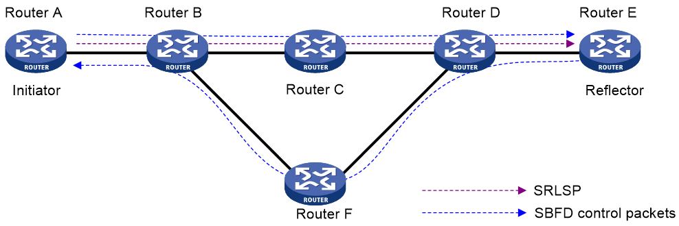
An SBFD session involves the following roles:
· Initiator—Periodically sends SBFD control packets to detect connectivity to remote entities. The initiator injects SBFD control packets into an MPLS TE tunnel or LDP LSP. The initiator initiates SBFD sessions and maintains SBFD session state.
· Reflector—Listens for incoming SBFD control packets on local entities and replies with response SBFD control packets.
As shown in Figure 1, in an SR-based MPLS TE tunnel, the SRLSP from Router A to Router E is considered available if Router A (initiator) can receive response SBFD control packets from Router E (reflector).
Figure 1 Initiator and reflector in SBFD
Restrictions and guidelines: SBFD configuration
A node can act as the initiator of one session and the reflector of another session at the same time.
An SBFD session can only be established statically. You must manually specify the remote discriminator for an SBFD session.
SBFD tasks at a glance
To configure SBFD, perform the following tasks:
¡ Configuring the initiator for LDP LSP detection
¡ Configuring the initiator for MPLS TE tunnel detection
Configuring the initiator
Restrictions and guidelines
The remote discriminator in SBFD control packets sent by the initiator must be specified in the sbfd local-discriminator command on the reflector. If the discriminator is not specified on the reflector, the reflector does not reply with response SBFD control packets.
Configuring the initiator for LDP LSP detection
1. Enter system view.
system-view
2. Enable BFD for MPLS.
mpls bfd enable
By default, BFD for MPLS is disabled.
For more information about this command, see MPLS OAM commands in MPLS Command Reference.
3. (Optional.) Set the detection time multiplier.
bfd multi-hop detect-multiplier value
The default setting is 5.
4. (Optional.) Set the minimum interval for sending SBFD control packets.
bfd multi-hop min-transmit-interval interval
The default setting is 400 milliseconds.
5. Configure SBFD to verify LSP connectivity for an FEC.
mpls sbfd dest-addr mask-length [ nexthop nexthop-address ] remote remote-id [ template template-name ]
By default, SBFD is not configured to verify LSP connectivity for an FEC.
For more information about this command, see MPLS OAM commands in MPLS Command Reference.
Configuring the initiator for MPLS TE tunnel detection
1. Enter system view.
system-view
2. Enable BFD for MPLS.
mpls bfd enable
By default, BFD for MPLS is disabled.
For more information about this command, see MPLS OAM commands in MPLS Command Reference.
3. (Optional.) Set the detection time multiplier.
bfd multi-hop detect-multiplier value
The default setting is 5.
4. (Optional.) Set the minimum interval for sending SBFD control packets.
bfd multi-hop min-transmit-interval interval
The default setting is 400 milliseconds.
5. Enter the view of an MPLS TE tunnel interface.
interface tunnel number [ mode mpls-te ]
6. Enable SBFD to verify MPLS TE tunnel connectivity.
mpls sbfd remote remote-id [ template template-name ]
By default, SBFD is not enabled for an MPLS TE tunnel.
For more information about this command, see MPLS OAM commands in MPLS Command Reference.
Configuring the reflector
Restrictions and guidelines
If you configure an IPv4 address as the local discriminator, the device automatically converts it to an integer. Configure an IPv4 address local discriminator only when it is required for interoperation with a third-party device.
The reflector replies with a response SBFD control packet only when the remote discriminator in the SBFD control packet sent from the initiator is specified in the sbfd local-discriminator command.
Procedure
1. Enter system view.
system-view
2. Configure a local discriminator.
sbfd local-discriminator { ipv4-address | integer-value }
By default, no local discriminator is configured.
You can execute this command multiple times to configure multiple local discriminators.
Configuring a BFD template
About configuring a BFD template
You can configure BFD parameters for LSPs and MPLS TE tunnels through a BFD template.
Procedure
1. Enter system view.
system-view
2. Create a BFD template and enter BFD template view.
bfd template template-name
3. Set the detection time multiplier.
bfd detect-multiplier value
The default setting is 5.
4. Set the minimum interval for sending SBFD control packets.
bfd min-transmit-interval interval
The default setting is 400 milliseconds.
Display and maintenance commands for SBFD
Execute the display command in any view.
|
Task |
Command |
|
Display SBFD session information. |
display sbfd session { initiator | reflector } [ discriminator value | verbose ] |