- Table of Contents
- Related Documents
-
| Title | Size | Download |
|---|---|---|
| 01-SPBM configuration | 634.48 KB |
Customer network port, provider network port
Formation and maintenance of ISIS-SPB adjacencies
B-VLAN to ECT algorithm mapping
Fast channel for quick spread of LSPs
Configuration restrictions and guidelines
Feature compatibility requirements
Configuring basic SPBM settings on BEBs and BCBs
Configuring MST region parameters
Configuring customer-side settings on BEBs
Assigning a B-VLAN to an SPB VSI
Configuring Ethernet service instances on BEBs
Configuring SPBM multicast settings
Configuring the SPBM multicast replication mode on BEBs
Optimizing traffic distribution
Setting a link metric value for a provider network port
Mapping B-VLANs to an ECT algorithm
Performing ECT migration for an SPB VSI
Enabling dynamic hostname exchange
Tuning ISIS-SPB adjacency maintenance settings
Tuning the SPF calculation timer
Configuring the control MAC address for ISIS-SPB
Configuring ISIS-SPB authentication
Configuring ISIS-SPB adjacency authentication
Configuring ISIS-SPB area authentication
Configuring Graceful Restart for ISIS-SPB
Configuring SNMP notifications and context for SPBM
Enabling ISIS-SPB adjacency change logging
Displaying and maintaining SPBM
Basic SPBM configuration example
SPBM with head-end replication configuration example
SPBM with tandem replication configuration example
ECT migration by changing B-VLAN example
ECT migration by changing ECT algorithm example
SPBM NSR configuration example
SPBM overview
IEEE 802.1aq Shortest Path Bridging (SPB) enables multipath routing in an Ethernet mesh network by using IS-IS as the control protocol. The technology allows all paths to be active, supports equal cost paths, and provides shortest path forwarding in an Ethernet mesh network. IEEE 802.1aq SPB provides faster convergence, higher link efficiency, and larger Layer 2 topologies than conventional spanning tree protocols such as MSTP.
Shortest path bridging MAC mode (SPBM) is one bridging method of IEEE 802.1aq SPB. This method encapsulates Ethernet frames into MAC-in-MAC frames in compliance with IEEE 802.1ah PBB.
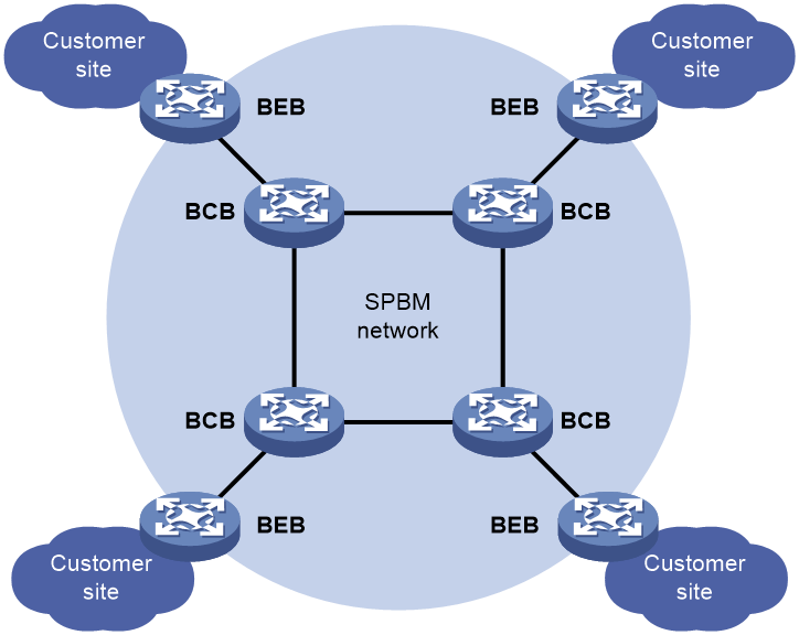
SPBM network model
As shown in Figure 1, the SPBM network includes backbone edge bridges and backbone core bridges.
Backbone edge bridges connect customer sites to the SPBM network.
The nodes in the SPBM network run ISIS-SPB to prevent loops and calculate the shortest path for a frame.
Terminology
AC
An attachment circuit (AC) is a physical or virtual link that connects a customer site to a backbone edge bridge.
Area
An SPBM area is a subdomain of an SPBM network. The device supports only one area.
BCB
Backbone core bridges (BCBs) are core nodes of an SPBM network. They are identical to the P devices in an MPLS VPN network. BCBs forward MAC-in-MAC frames based on the B-MAC and B-VLAN. They do not learn customer MAC (C-MAC) addresses.
BEB
Backbone edge bridges (BEBs) are edge nodes of the SPBM network. They are identical to PEs in an MPLS VPN network. BEBs encapsulate customer frames into MAC-in-MAC frames before forwarding them to the SPBM network. BEBs also decapsulate MAC-in-MAC frames before sending them to a customer site.
B-MAC, B-VLAN
Backbone MAC addresses (B-MACs) are bridge MAC addresses associated with SPBM bridges. Backbone VLANs (B-VLANs) are VLANs assigned by the service provider for transmitting customer traffic on the SPBM network.
For customer frames to be transmitted across an SPBM network, the ingress BEB encapsulates them in MAC-in-MAC format. In the outer frame header, the source MAC address is a B-MAC of the ingress BEB, and the destination MAC is a B-MAC of the egress BEB. All devices in the SPBM network forward the MAC-in-MAC frames based on the destination B-MAC and B-VLAN.
Customer network port, provider network port
On a BEB, a customer network port (CNP) connects to a customer site and a provider network port (PNP) connects to the SPBM network.
Ethernet service instance
An Ethernet service instance provides forwarding service for a set of VLANs. To extend VLANs across customer sites over an SPBM network, you must configure Ethernet service instances on BEBs' customer edge ports and map them to SPB VSIs.
For more information about Ethernet service instances, see VPLS in MPLS Configuration Guide.
I-SID
A backbone service instance identifier (I-SID) uniquely identifies a MAC-in-MAC service instance (also called an "SPB VSI") provided by the service provider.
ISIS-SPB
ISIS-SPB is the control protocol for an SPBM network to calculate shortest path trees (SPTs) and maintain adjacencies between neighbors.
LSDB
A link state database (LSDB) contains the states of all links in an SPBM network.
MAC-in-MAC
SPBM encapsulates Ethernet frames into MAC-in-MAC frames by using 802.1ah PBB encapsulation. For more information about the MAC-in-MAC frame format, see "SPBM packet types."
Customer frames are encapsulated in MAC-in-MAC format at edges of the SPBM network before they are forwarded from one customer site to another.
PW
Pseudo wires (PWs) are MAC-in-MAC tunnels established over the SPBM network for transmitting customer traffic.
PWs are established between BEBs. BCBs do not set up PWs.
On an interface, incoming frames are assigned to the same PW if they match the packet match criterion of the same Ethernet service instance.
SPB VSI
An SPB virtual switch instance (SPB VSI) provides MAC-in-MAC tunnel service for Ethernet service instances. An SPB VSI acts as a virtual switch. It has all the functionality of a conventional Ethernet switch, including source MAC address learning, MAC address aging, and flooding. Each SPB VSI is uniquely identified by an I-SID. For more information about VSIs, see VPLS in MPLS Configuration Guide.
System ID
In the SPBM network, each device is uniquely identified by a 6-byte system ID. The system ID is automatically generated by ISIS-SPB.
SPBM packet types
SPBM packets include ISIS-SPB control packets and SPBM data packets.
ISIS-SPB control packets
ISIS-SPB control packets include hello, LSP, and SNP. All SPBM control packets are encapsulated in 802.1q.
Hello
SPBM neighbors send IS-IS hello (IIH) PDUs to establish and maintain adjacencies.
LSP
Adjacent SPBM neighbors send link state PDUs (LSPs) to advertise topology data.
SNP
Adjacent SPBM neighbors exchange sequence number PDUs (SNPs) for LSDB synchronization.
SNPs include complete SNP (CSNP) and partial SNP (PSNP).
· CSNP—Contains the digest of each LSP in the LSDB. Adjacent routers exchange CSNPs to maintain LSDB synchronization.
· PSNP—Contains the sequence numbers of recently received LSPs. An SPBM node uses a PSNP to acknowledge LSPs or to request needed LSPs from a neighbor.
SPBM data packet
SPBM data packets use the IEEE 802.1ah MAC-in-MAC frame format, as shown in Figure 2.
Figure 2 IEEE 802.1ah-compliant MAC-in-MAC frame format
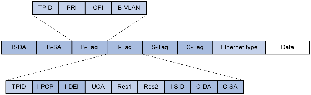
Table 1 IEEE 802.1ah encapsulated frame header fields
|
Field |
Description |
|
B-DA |
Destination B-MAC that identifies the destination BEB. |
|
B-SA |
Source B-MAC. It is a known MAC address of the BEB that encapsulates the MAC-in-MAC frame. |
|
B-Tag |
B-VLAN tag identifies the VLAN ID and priority of the frame in the SPBM network. The TPID in the tag is fixed at 0x8100. |
|
I-Tag |
Backbone service instance tag contains the following subfields: · TPID—A value fixed at 0x88E7 to identify the frame as an 802.1ah encapsulated frame. · I-PCP—Transmission priority of the frame on the BEB. · I-DEI—Drop priority of the frame on the BEB. · I-SID—Backbone service instance identifier. · C-DA—Customer destination MAC address. · C-SA—Customer source MAC address. |
|
S-Tag |
This field contains the outer customer VLAN ID and priority. |
|
C-Tag |
This field contains the inner customer VLAN ID and priority. |
Working mechanisms
To forward Layer 2 traffic between customer sites across an SPBM network, you must configure Ethernet service instances on BEBs' customer network ports, and map Ethernet service instances to SPB VSIs.
SPBM uses ISIS-SPB in the control plane to calculate shortest path trees. It uses IEEE 802.1ah PBB encapsulation in the data plane to encapsulate and forward traffic.
SPBM uses the following generic process to calculate SPTs and forward traffic:
1. BEBs and BCBs send ISIS-SPB P2P hellos to establish and maintain adjacencies.
2. Adjacent nodes send LSPs to advertise their respective topology data. Eventually, the LSDBs of all nodes are synchronized.
3. Each node selects the forwarding path:
a. Each node runs SPF to calculate the shortest path from itself to each of the other nodes.
b. If equal-cost paths are available, each node runs ECT to choose the best forwarding path.
c. The nodes populate their respective FDB and FIB tables with the forwarding path.
4. BEBs establish PWs over the SPBM network for transmitting customer traffic.
Formation and maintenance of ISIS-SPB adjacencies
ISIS-SPB only supports point-to-point links within an IS-IS level 1. It sends P2P hellos between directly connected nodes to form and maintain adjacencies. To forward traffic on an adjacency, two SPBM neighbors must meet the following requirements:
· The neighbors have the same configuration digest for MSTI 4092.
· The neighbors have the same B-VLAN to ECT algorithm mapping.
· The neighbors have valid link metric values.
|
|
NOTE: In SPBM, you must map all B-VLANs to MSTI 4092. |
MAC address learning
In an SPBM network, BEBs perform typical source MAC learning in the data plane to learn C-MACs, but BCBs do not learn C-MACs.
BCBs forward MAC-in-MAC traffic by destination B-MAC and B-VLAN, which are advertised through ISIS-SPB in the control plane. As a result, BCBs do not need to maintain a large MAC address table.
Data paths
For the forwarding process for known unicast frames, see "Unicast."
To avoid loops, SPBM does not support broadcast. BEBs flood broadcast, multicast, and unknown unicast frames to the SPBM network as multicast frames. For the flooding process, see "Multicast."
Unicast
For an intra-site known unicast frame, the ingress BEB performs typical MAC address table lookup.
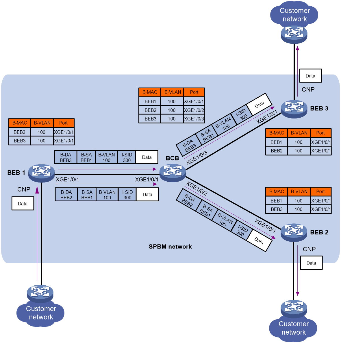
For a known inter-site unicast frame, the following forwarding process takes place, as shown in Figure 3:
1. The ingress BEB performs the following tasks:
a. Assigns the frame to the correct Ethernet service instance based on the outer VLAN.
b. Learns the source MAC address.
c. Looks up the destination MAC address in the Ethernet service instance's Ethernet address table.
2. If the outgoing interface is a provider network port, the ingress BEB performs the following tasks:
a. Encapsulates the frame in IEEE 802.1ah format.
b. Sends the frame out of the unicast PW to the egress BEB.
The B-DA field in the outer frame header is the B-MAC of the egress BEB.
3. Each BCB on the unicast PW forwards the frame based on the B-MAC and B-VLAN in the outer frame header until it reaches the egress BEB.
4. The egress BEB removes the outer frame header and forwards the frame to the destination customer MAC address.
Figure 3 MAC-in-MAC unicast traffic over an SPBM network

Multicast
SPBM floods broadcast, customer multicast, and unknown customer unicast as multicast traffic.
SPBM supports the following replication methods for multicast:
· Head-end replication—Replicates frames at the ingress BEB for frames to enter the SPBM network. This method is suitable for SPB VSIs that have sparse multicast traffic. It does not require BCBs to maintain multicast FDB entries.
· Tandem replication—Replicates frames only at the node where the shortest path tree forks. This method is suitable for SPB VSIs that have dense multicast traffic. It requires BCBs to maintain multicast FDB entries.
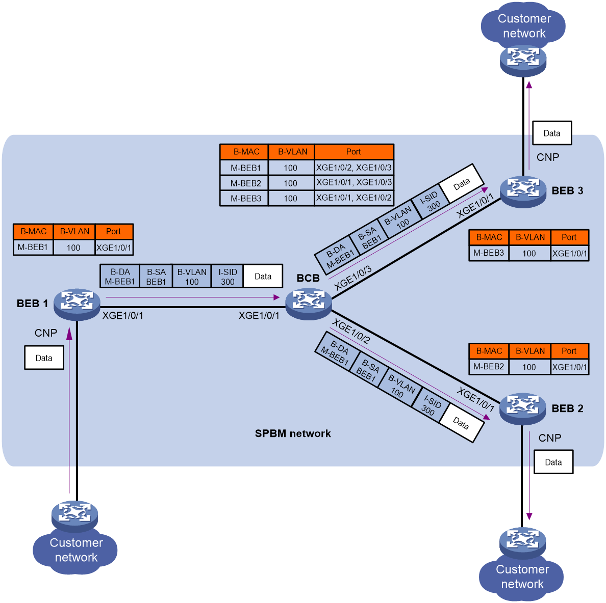
In head-end replication, the ingress BEB performs the following tasks, as shown in Figure 4:
1. Replicates the customer frame for each destination BEB.
2. Encapsulates each replica in one unicast frame.
3. Sends the unicast frames to the destination BEBs.
In tandem replication, the source BEB encapsulates a frame with a B-DA multicast address that uniquely identifies itself and the SPBM service. When this frame arrives at the BCB where the shortest path tree forks, the BCB replicates one frame for each destination BEB, as shown in Figure 5.
SPBM multicast address
Figure 6 SPBM multicast address format

Table 2 SPBM multicast address fields
|
Field |
Description |
|
M |
1-bit multicast flag. Its value is fixed at 1. |
|
L |
1-bit local flag bit. Its value is fixed at 1. |
|
TYP |
2-bit SPSource ID type. Its value is fixed at 0. |
|
SPSource ID |
20-bit SPSource ID. |
|
I-SID |
24-bit SPB VSI identifier. |
In Figure 6, LSB represents the lower 4 bits of a byte, and MSB represents the higher 4 bits of a byte. The first byte of an SPBM multicast address is identical to the combination of the first 4 bits of the SPSource ID field, the TYP field, the L field, and the M field. For example, the hexadecimal form of the first byte (E3) in the SPBM multicast address E386070006E9 is 11100011. This byte consists of 1110 (first 4 bits of SPSource ID), 00 (TYP), 1 (L), and 1 (M).
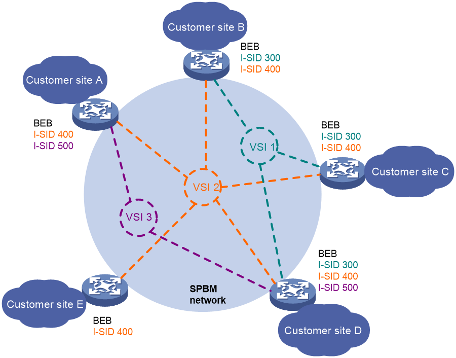
Multiple SPB VSIs
For example, the network in Figure 7 has the following SPB VSIs:
· I-SID 300 extends traffic to customer sites B, C, and D.
· I-SID 400 extends traffic to all customer sites.
· I-SID 500 extends traffic to customer sites A and D.
All traffic in one SPB VSI is transmitted in one B-VLAN. Different SPB VSIs can use the same B-VLAN to transmit traffic. Traffic of different SPB VSIs is isolated by I-SID.
Figure 7 Multiple SPB VSIs
Load balancing
To balance traffic between forwarding paths, you can map B-VLANs to different ECT algorithms. When a path is approaching congestion, you can move part of traffic on one path to another by moving an I-SID from one ECT algorithm to another.
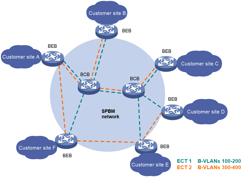
B-VLAN to ECT algorithm mapping
For balanced traffic distribution, SPBM supports calculating one SPT for a set of B-VLANs by using different ECT algorithms. IEEE 802.1aq SPB provides 16 ECT algorithms. Each algorithm represents a set of tie-break rules. As a result, you can have up to 16 forwarding paths in an SPBM network.
Figure 8 shows two SPTs that are calculated by using two ECT algorithms.
Figure 8 Multiple SPTs in an SPBM network
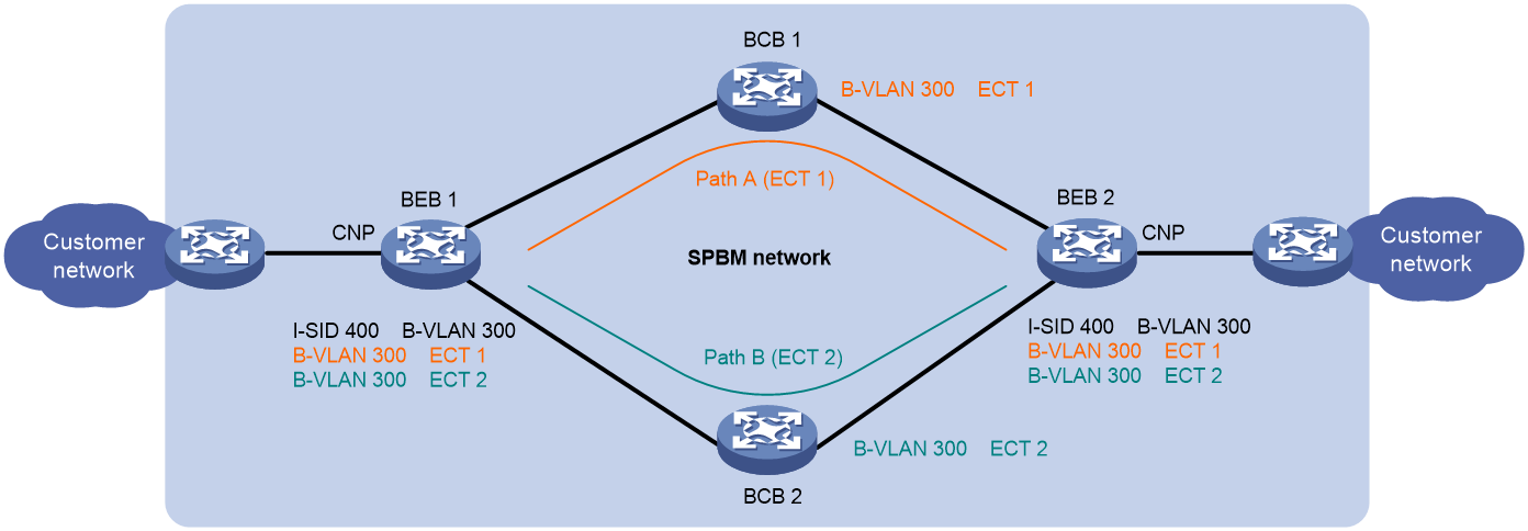
ECT migration
ECT migration enables an I-SID to migrate from one ECT algorithm to another with minimum traffic loss.
To prevent traffic loss, ECT migration was designed based on the idea of make-before-break. All nodes in the SPBM network maintain the old path for the I-SID before a new path is set up. The SPBM nodes remove the old path only after all affected traffic has been moved from the old path to the new path for the I-SID.
As shown in Figure 9, two paths (path A and path B) are available between BEB 1 and BEB 2. B-VLAN 300 has been using path A. As path A is getting congested, you can perform ECT migration to move part of B-VLAN traffic (for example, traffic in I-SID 400) to path B.
Loop prevention
SPBM nodes collect topology data independently to calculate forwarding paths. Transient loops might occur during SPT recalculation caused by a network flapping because the latency varies for an LSP to reach the SPBM nodes. To prevent transient loops, SPBM uses the Agreement Protocol (AP) to exchange LSDB synchronization status. After a topology recalculation, ISIS-SPB issues new forwarding entries to the data plane only if topology data is synchronized between the SPBM node and its adjacent neighbors.
|
|
NOTE: In this document, "AP" refers to agreement protocol. In other documents, "AP" can also refer to access points. |
Fast channel for quick spread of LSPs
The fast channel feature provides a quicker LSP propagation method than conventional LSP propagation. This feature spreads ISIS-SPB LSPs in the SPBM network by forwarding LSPs as data packets along the SPT in a dedicated SPB VSI. An SPBM node does not need to complete updating its LSDB before it propagates the topology change to the next node.
The I-SID for the fast-channel VSI is 255. To use the fast-channel feature, you must create a VSI and assign I-SID 255 to the VSI.
You cannot associate any Ethernet service instance with the VSI that uses I-SID 255 for data transmission.
Protocols and standards
· IEEE 802.1aq, Shortest Path Bridging
· IEEE 802.1ah, Virtual Bridged Local Area Networks Amendment 7: Provider Backbone Bridges
· ISO 10589, ISO IS-IS Routing Protocol
· RFC 6329, IS-IS Extensions Supporting IEEE 802.1aq Shortest Path Bridging
Configuring SPBM
Configuration restrictions and guidelines
For SPBM to operate correctly, follow the restrictions and guidelines in this section when you configure SPBM.
Feature compatibility requirements
When you use SPBM in conjunction with other features, follow the restrictions and guidelines in Table 3.
Table 3 SPBM and other features compatibility
|
Feature |
Restrictions and guidelines |
|
IRF |
You must use the irf mac-address persistent always command to prevent the IRF bridge MAC address from changing after the address owner leaves. For more information about IRF bridge MAC persistence, see Virtual Technologies Command Reference. |
|
IS-IS |
Provider network ports on BEBs and BCBs cannot be used for setting up standard IS-IS adjacencies. |
|
Spanning tree |
The spanning tree mode must be set to MSTP. For SPBM neighbors to establish adjacencies, you must map all B-VLANs to MSTI 4092, and make sure their in-between links have connectivity. To forward traffic on an SPBM network, you must assign all SPBM nodes to the same MST region. For SPBM to run correctly, make sure MSTI 4092 is not used by RRPP or Smart Link. For more information about RRPP and Smart Link, see High Availability Configuration Guide. |
|
Static MAC |
If a B-MAC is the same as a static MAC entry in the MAC address table, remove the static MAC entry. The device can forward SPBM packets to the B-MAC only after the conflict is removed. |
|
VLAN |
Do not use B-VLANs for other purposes such as VLAN interfaces. Before specifying a VLAN as a B-VLAN, you must remove all features that have been configured on the VLAN. You must configure the provider network ports on BEBs and BCBs as trunk or hybrid ports, and assign them to all B-VLANs as tagged VLAN members. ISIS-SPB protocol frames are transmitted untagged on links. To prevent SPBM-enabled interfaces from dropping these frames, assign each SPBM-enabled interface to the port VLAN (PVID) as an untagged member. Make sure the PVIDs have been created on the device. |
Licensing requirements
SPBM requires a license to run on the device. For information about feature licensing, see Fundamentals Configuration Guide.
SPBM configuration task list
|
Tasks at a glance |
Remarks |
|
(Required.) Configuring basic SPBM settings on BEBs and BCBs: |
You must map B-VLANs to MSTI 4092, and enable SPBM both globally and on the provider network ports in the SPBM network. |
|
(Required.) Configuring customer-side settings on BEBs: |
Configure customer-side settings to map Ethernet service instances to SPB VSIs for extending VLANs across different sites. Each Ethernet service instance represents a set of VLANs. |
|
Configuring SPBM multicast settings: · (Required.) Configuring the SPBM multicast replication mode on BEBs · (Optional.) Setting the SPSource ID |
Make sure the multicast replication mode for an SPB VSI is the same across all BEBs. |
|
(Optional.) Optimizing traffic distribution: · Setting a link metric value for a provider network port |
To obtain a desirable path, you can change the bridge priority and link metric values. By default, all B-VLANs are mapped to ECT algorithm 1. To optimize traffic distribution, map B-VLANs to different ECT algorithms. |
|
(Optional.) Configuring the AP mode |
Perform this task to prevent temporary loops that might occur when the topologies of SPBM neighbors do not match. |
|
(Optional.) Optimizing the SPBM network: · Enabling dynamic hostname exchange · Configuring ISIS-SPB throttling timers: ¡ Tuning ISIS-SPB adjacency maintenance settings ¡ Tuning the SPF calculation timer |
To ensure correct path selection and traffic forwarding, make sure B-VLAN to ECT algorithm mappings and ISIS-SPB timer settings are consistent across the network. Dynamic hostname exchange enables you to identify SPBM nodes with symbolic hostnames. |
|
(Optional.) Configuring ISIS-SPB authentication: |
Configure ISIS-SPB authentication to improve security in an SPBM network. |
|
(Optional.) Configuring Graceful Restart for ISIS-SPB |
Enable this feature before you re-enable SPBM or perform an active/standby switchover. Graceful Restart ensures nonstop forwarding while ISIS-SPB processes are re-establishing their adjacency. |
|
(Optional.) Enabling NSR for ISIS-SPB |
NSR ensures nonstop services when ISIS-SPB has redundant processes on multiple IRF member devices. |
|
(Optional.) Configuring SNMP notifications and context for SPBM |
Configure SNMP notifications for SPBM to send SPBM event notifications to an NMS. |
|
(Optional.) Enabling ISIS-SPB adjacency change logging |
Enable this feature to track all adjacency changes. To suppress frequent adjacency change messages, disable this feature. |
Configuring basic SPBM settings on BEBs and BCBs
For SPBM to run, you must configure all settings in this section on all BEBs and BCBs.
Configuring MST region parameters
|
|
CAUTION: Changing MST region settings causes spanning tree recalculation. Make sure you understand the impact on your network before you activate the MST region settings. |
SPBM runs on MSTI 4092. For two SPBM neighbors to establish an adjacency, you must activate MSTI 4092 on both neighbors and make sure their in-between link has connectivity. To forward traffic on the link, you must also configure the same MST region parameters on the devices, including:
· Format selector. The value for this parameter is fixed at 0.
· Region name.
· Revision level.
· VLAN-to-MSTI mapping table.
For more information about MST region configuration commands, see spanning tree commands in Layer 2—LAN Switching Command Reference.
To configure MST region parameters on a BEB or BCB:
|
Step |
Command |
Remarks |
|
1. Enter system view. |
system-view |
N/A |
|
2. Enter MST region view. |
stp region-configuration |
N/A |
|
3. Configure the MST region name. |
region-name name |
The default MST region name is the MAC address of the device. |
|
4. Set the MSTP revision level. |
revision-level level |
The default MSTP revision level is 0. |
|
5. Map B-VLANs to MSTI 4092. |
instance instance-id vlan vlan-id-list |
By default, all VLANs are mapped to the CIST (MSTI 0). The value for the instance-id argument must be 4092. |
|
6. Activate the MST region configuration. |
active region-configuration |
N/A |
Enabling SPBM
You must enable SPBM both globally and on the provider network ports on all BEBs and BCBs in the SPBM network.
To enable SPBM:
|
Step |
Command |
Remarks |
|
1. Enter system view. |
system-view |
N/A |
|
2. Enable SPBM globally and enter SPBM view. |
spbm |
By default, SPBM is disabled globally. |
|
3. Return to system view. |
quit |
N/A |
|
4. Enter Layer 2 Ethernet interface view or Layer 2 aggregate interface view. |
interface interface-type interface-number |
N/A |
|
5. Enable SPBM on the interface. |
spbm enable |
By default, SPBM is disabled on interfaces. |
Configuring customer-side settings on BEBs
All tasks in this section are required.
Enabling L2VPN
For SPBM settings to take effect, you must enable L2VPN on BEBs.
If L2VPN is also enabled on BCBs and the BCBs use aggregate interfaces to connect to BEBs, you must disable the static source check feature on the aggregate interfaces. This restriction applies to the following switches:
· The S6800-54HF switch.
· The S6800-54HT switch.
· The S6800-2C-FC switch.
· S6800 switches labeled with the following product codes:
¡ LS-6800-2C-H1.
¡ LS-6800-4C-H1.
¡ LS-6800-32Q-H1.
¡ LS-6800-54QF-H1.
¡ LS-6800-54QF-H3.
¡ LS-6800-54QT-H1.
¡ LS-6800-54QT-H3.
To disable the static source check feature, use the undo mac-address static source-check enable command. For information about the static source check feature, see Layer 2—LAN Switching Configuration Guide.
To enable L2VPN:
|
Step |
Command |
Remarks |
|
1. Enter system view. |
system-view |
N/A |
|
2. Enable L2VPN. |
l2vpn enable |
By default, L2VPN is disabled. |
Creating an SPB VSI
SPBM uses a unique I-SID to identify an SPB VSI. An SPB VSI's I-SID must be the same across the SPBM network.
I-SID 255 is reserved for the fast channel. You cannot associate any Ethernet service instance with the VSI that uses I-SID 255.
To use the fast-channel feature, you must create a VSI and assign I-SID 255 to the VSI.
To create an SPB VSI:
|
Step |
Command |
Remarks |
|
1. Enter system view. |
system-view |
N/A |
|
2. Create a VSI. |
vsi vsi-name |
By default, no VSIs exist. |
|
3. Assign an SPB I-SID to the VSI. |
spb i-sid i-sid |
By default, a VSI does not have an SPB I-SID. You can configure one SPB I-SID and one PBB I-SID for one VSI, but the two I-SIDs cannot be the same. For more information about PBB, see Layer 2—LAN Switching Configuration Guide. |
Assigning a B-VLAN to an SPB VSI
For an SPB VSI, you must specify the same I-SID and B-VLAN across all BEBs and BCBs. You can assign only one B-VLAN to an SPB VSI, but different SPB VSIs can use the same B-VLAN.
To assign a B-VLAN to an SPB VSI:
|
Step |
Command |
Remarks |
|
1. Enter system view. |
system-view |
N/A |
|
2. Enter VSI view. |
vsi vsi-name |
N/A |
|
3. Enter SPB I-SID view. |
spb i-sid i-sid |
N/A |
|
4. Assign a B-VLAN to the SPB VSI. |
b-vlan vlan-id |
By default, an SPB VSI does not have a B-VLAN. |
Configuring Ethernet service instances on BEBs
For a BEB to identify VLANs that must be extended across sites, you must configure Ethernet service instances on its customer network ports to map VLANs to SPB VSIs.
When you configure Ethernet service instances, follow these restrictions and guidelines:
· An SPB VSI can be mapped to multiple Ethernet service instances on the same port or different ports.
· For correct traffic processing, do not use the outer VLAN specified with the encapsulation command to provide any other services, including Layer 2 and Layer 3 services.
|
|
NOTE: The outer VLAN refers to the C-VLAN for a single-tagged frame and the S-VLAN for a double-tagged frame. |
· You can create Ethernet service instances on both a Layer 2 aggregate interface and its member ports and map the Ethernet service instances to VSIs. However, the Ethernet service instances on the aggregation member ports are down. For the Ethernet service instances to come up, you must remove the aggregation member ports from the aggregation group.
· If an Ethernet service instance is configured with the encapsulation untagged criterion on a Layer 2 Ethernet or aggregate interface, you cannot apply a QoS policy for VLAN tag nesting to that interface. For more information about VLAN tag nesting, see QoS configuration in ACL and QoS Configuration Guide.
For more information about Ethernet service instance configuration commands, see VPLS commands in MPLS Command Reference.
To configure an Ethernet service instance on a customer network port:
|
Step |
Command |
Remarks |
|
1. Enter system view. |
system-view |
N/A |
|
2. Enter Layer 2 Ethernet interface view or Layer 2 aggregate interface view. |
interface interface-type interface-number |
N/A |
|
3. Configure the port link type. |
port link-type { access | trunk | hybrid } |
The default port link type is access. |
|
4. Assign the port to VLANs. |
· Access link type: · Trunk link type: · Hybrid link type: |
N/A |
|
5. Create an Ethernet service instance and enter its view. |
service-instance instance-id |
By default, no Ethernet service instances exist. |
|
6. Configure a frame match criterion. |
· encapsulation s-vid vlan-id [ only-tagged ] · encapsulation s-vid vlan-id-list · encapsulation { default | tagged | untagged } |
Use one of the commands to configure a frame match criterion. By default, an Ethernet service instance does not contain a frame match criterion. |
|
7. Map the Ethernet service instance to the SPB VSI. |
xconnect vsi vsi-name [ access-mode { ethernet | vlan } ] * |
By default, an Ethernet service instance is not mapped to any SPB VSI. VLAN access mode is not supported by Ethernet service instances that use the default, tagged, untagged, or s-vid vlan-id-list criterion. |
Configuring SPBM multicast settings
Configuring the SPBM multicast replication mode on BEBs
SPBM supports head-end replication and tandem replication for broadcast, multicast, and unknown unicast traffic.
Head-end replication is suitable for service instances that have sparse multicast traffic. Tandem replication is suitable for service instances that have dense multicast traffic.
Multicast replication mode must be the same across all BEBs.
To configure the SPBM multicast replication mode:
|
Step |
Command |
Remarks |
|
1. Enter system view. |
system-view |
N/A |
|
2. Enter VSI view. |
vsi vsi-name |
N/A |
|
3. Enter I-SID view. |
spb i-sid i-sid |
N/A |
|
4. Configure the SPBM multicast mode. |
multicast replicate-mode { head-end | tandem } |
By default, head-end replication applies. |
Setting the SPSource ID
An SPSource ID uniquely identifies a device in an SPBM network. By default, the device generates an SPSource ID automatically.
If you set an SPSource ID manually, make sure the ID is unique on the SPBM network.
To set an SPSource ID for the device:
|
Step |
Command |
Remarks |
|
1. Enter system view. |
system-view |
N/A |
|
2. Enter SPBM view. |
spbm |
N/A |
|
3. Set SPSource ID. |
spsource spsource-id |
By default, the device generates an SPSource ID automatically. |
Optimizing traffic distribution
Setting the bridge priority
In conjunction with the system ID, the SPBM bridge priority forms the SPBM bridge ID. The SPBM bridge ID is a tie-breaker used in the ECT algorithms for choosing the forwarding path.
To set the SPBM bridge priority:
|
Step |
Command |
Remarks |
|
1. Enter system view. |
system-view |
N/A |
|
2. Enter SPBM view. |
spbm |
N/A |
|
3. Set a bridge priority. |
bridge-priority priority |
The default bridge priority is 32768. |
Setting a link metric value for a provider network port
The following are methods to assign a link metric value to an interface:
· Set an interface-specific value in interface view.
· Set a global value in SPBM view. This global value applies to all SPBM-enabled interfaces.
· Set a bandwidth reference in SPBM view for the system to calculate a value automatically for the interface.
The system chooses a link metric value for an interface in order of interface-specific value, global value, and autocalculated value.
Setting a port-specific link metric value
|
Step |
Command |
Remarks |
|
1. Enter system view. |
system-view |
N/A |
|
2. Enter Layer 2 Ethernet interface view or Layer 2 aggregate interface view. |
interface interface-type interface-number |
N/A |
|
3. Set a port-specific link metric value. |
spbm cost cost-value |
By default, automatic link metric calculation applies. |
Setting the global link metric value
|
Step |
Command |
Remarks |
|
1. Enter system view. |
system-view |
N/A |
|
2. Enter SPBM view. |
spbm |
N/A |
|
3. Set a global SPBM link metric value. |
circuit-cost cost-value |
By default, no global SPBM link metric value is set. |
Setting the bandwidth reference for automatic link metric calculation
ISIS-SPB automatically calculates a link metric value for an interface if both the global and interface-specific link metric value are not set.
The following is the calculation formula:
Link metric value=(Reference bandwidth/Interface rate)x10
The value range for the link metric value is 1 to 16777214.
To set the bandwidth reference for automatic link metric calculation:
|
Step |
Command |
Remarks |
|
1. Enter system view. |
system-view |
N/A |
|
2. Enter SPBM view. |
spbm |
N/A |
|
3. Set the reference bandwidth for automatic link metric calculation. |
bandwidth-reference value |
The default bandwidth reference is 40000 Mbps. |
Mapping B-VLANs to an ECT algorithm
An ECT algorithm represents a set of tie-breakers for calculating SPTs.
To improve link efficiency in an SPBM network, you can distribute B-VLAN traffic along different paths by mapping B-VLANs to different ECT algorithms.
To ensure correct SPT calculation for a B-VLAN, the B-VLAN to ECT algorithm mappings must be the same across the SPBM network.
For more information about the ECT algorithms, see IEEE 802.1aq SPB.
To map a list of B-VLANs to an ECT algorithm:
|
Step |
Command |
Remarks |
|
1. Enter system view. |
system-view |
N/A |
|
2. Enter SPBM view. |
spbm |
N/A |
|
3. Map B-VLANs to an ECT algorithm. |
ect ect-index b-vlan vlan-id-list |
By default, all B-VLANs are mapped to ECT algorithm 1. |
Performing ECT migration for an SPB VSI
To move traffic from an overloaded path to a path that has less traffic, you can change B-VLAN to ECT algorithm mappings by using the ect command or by performing ECT migration. ECT migration provides more granular traffic control than the ect command.
· Using the ect command, you can move all traffic of a B-VLAN from one path to another. The B-VLAN's traffic is disrupted before you complete B-VLAN to ECT algorithm remapping across the SPBM network.
· Using ECT migration, you can move traffic by I-SID without traffic loss.
To perform ECT migration:
1. On all BEBs and BCBs, create a new B-VLAN, assign the B-VLAN to MSTI 4092, and assign the provider network port to the B-VLAN:
|
Step |
Command |
Remarks |
|
1. Enter system view. |
system-view |
N/A |
|
2. (Optional.) Add a new B-VLAN. |
vlan |
Skip this step if you choose a VLAN that already exists. |
|
3. Return to the system view |
quit |
N/A |
|
4. Enter MST region view. |
stp region-configuration |
N/A |
|
5. Assign the VLAN to MSTI 4092. |
instance instance-id vlan vlan-list |
The value for the instance-id argument must be 4092. |
|
6. Activate the MST region configuration. |
active region-configuration |
N/A |
|
7. Return to system view. |
quit |
N/A |
|
8. Enter interface range view. |
interface range { interface-type interface-number [ to interface-type interface-number ] } &<1-5> |
Specify all provider network ports. |
|
9. Assign all provider network ports to the VLAN. |
· Assign trunk ports to the VLAN: · Assign hybrid ports to the VLAN: |
N/A |
|
10. Return to system view. |
quit |
N/A |
2. On all BEBs and BCBs, map the new B-VLAN to a different ECT algorithm than the old B-VLAN:
|
|
CAUTION: To avoid traffic disruption, you must verify that the new mapping has been added across the SPBM network before you proceed to the next task. |
|
Step |
Command |
Remarks |
|
1. Enter SPBM view. |
spbm |
Skip this step if you choose a VLAN that already exists. |
|
2. Map the new B-VLAN to a new ECT algorithm. |
ect ect-index b-vlan vlan-id-list |
This ECT algorithm must be different from the one mapped to the old B-VLAN. |
|
3. Verify that the mapping has been added. |
display spbm b-vlan [ vlan-id ] |
N/A |
|
4. Return to system view. |
quit |
N/A |
3. Assign the new B-VLAN to the SPB VSI on all BEBs:
|
Step |
Command |
|
1. Enter VSI view. |
vsi vsi-name |
|
2. Enter SPB I-SID view. |
spb i-sid i-sid |
|
3. Assign the new B-VLAN to the SPB VSI. |
b-vlan vlan-id |
|
|
NOTE: The SPB VSI's traffic will not be switched over to the new path until you assign the new B-VLAN to the SPB VSI on all BEBs. |
Configuring the AP mode
The Agreement Protocol (AP) prevents temporary loops that might occur when the topologies of SPBM neighbors do not match.
If AP is enabled, SPBM issues forwarding entries to the forwarding plane only if AP declares a topology match.
|
|
NOTE: In this document, "AP" refers to agreement protocol. In other documents, "AP" can also refer to access points. |
To configure the AP mode:
|
Step |
Command |
Remarks |
|
1. Enter system view. |
system-view |
N/A |
|
2. Enter SPBM view. |
spbm |
N/A |
|
3. Configure the AP mode. |
ap-mode { both | multicast | off } |
By default, AP is enabled for both multicast and unicast entries. SPBM issues a unicast or multicast entry to the forwarding plane only if AP declares a topology match. |
Optimizing the SPBM network
Perform the tasks in this section to optimize an SPBM network for bandwidth efficiency and high performance.
Enabling dynamic hostname exchange
ISIS-SPB uses a 6-byte system ID to represent a node in the network. This type of ID is difficult for administrators to identify devices when they examine ISIS-SPB adjacencies, FDB entries, and LSDB entries.
Dynamic hostname exchange enables you to assign a symbolic hostname to each SPBM node. ISIS-SPB advertises this information in the Dynamic hostname TLV in LSPs to remote LSDBs.
To enable dynamic hostname exchange:
|
Step |
Command |
Remarks |
|
1. Enter system view. |
system-view |
N/A |
|
2. Enter SPBM view. |
spbm |
N/A |
|
3. Configure a symbolic hostname. |
is-name is-name |
By default, dynamic hostname exchange is disabled, and no symbolic hostname is configured for the device. |
Tuning ISIS-SPB adjacency maintenance settings
ISIS-SPB uses the ISIS-SPB hello interval and the hello multiplier for adjacency establishment and maintenance.
Adjacency hold time sets the maximum amount of time for one SPBM node to retain the adjacency with another. This timer determines the amount of time it takes for an SPBM node to detect a failed link.
The adjacency hold time equals the ISIS-SPB hello interval multiplied by the hello multiplier.
An SPBM node sends its adjacency hold time in hello packets to update the adjacencies with its neighbor. The neighbor removes the adjacency with the advertising node and recalculates routes if it does not receive a hello packet before the timer expires.
Setting the ISIS-SPB hello interval
ISIS-SPB sends hellos over links to establish and maintain adjacencies between SPBM nodes.
A short interval improves network convergence time, but it requires more system resources.
To set the ISIS-SPB hello interval on an interface:
|
Step |
Command |
Remarks |
|
1. Enter system view. |
system-view |
N/A |
|
2. Enter Layer 2 Ethernet interface view or Layer 2 aggregate interface view. |
interface interface-type interface-number |
N/A |
|
3. Set the ISIS-SPB hello interval. |
spbm timer hello seconds |
The default hello interval is 10 seconds. The maximum adjacency hold time is 65535 seconds. If this value is exceeded, the original hello interval remains unchanged. |
Setting the hello multiplier for calculating the adjacency hold time
To set the multiplier for calculating the adjacency hold time on an interface:
|
Step |
Command |
Remarks |
|
1. Enter system view. |
system-view |
N/A |
|
2. Enter Layer 2 Ethernet interface view or Layer 2 aggregate interface view. |
interface interface-type interface-number |
N/A |
|
3. Set the hello multiplier. |
spbm timer holding-multiplier value |
The default multiplier is 3. The maximum adjacency hold time is 65535 seconds. If this value is exceeded, the original hello multiplier remains unchanged. |
Tuning ISIS-SPB LSP timers
Change LSP timer settings depending on network stability to increase the network convergence speed and protect CPU from unnecessary route recalculations.
|
LSP timer |
Functionality |
Tuning guidelines |
|
Minimum LSP transmit interval |
Sets the minimum interval for transmitting LSPs out of an interface. You can also set the number of LSPs that can be sent at each interval. |
Increase the interval to reduce LSP traffic in the network. Decrease the interval for quick LSDB synchronization. |
|
LSP lifetime |
Sets the amount of time that an LSP can be retained in an LSDB. |
Set the lifetime to a higher value than the LSP refresh interval. |
|
LSP refresh interval and LSP generation timer |
Control the update interval for an LSP. |
Increase the interval to protect the CPU from frequent LSP generation. Decrease the interval for quick reaction to topology change events. |
|
LSP fast-flooding |
Floods the first several LSPs that invoke SPF before SPF computation is started. |
Enable this feature for quick LSDB synchronization. |
Setting the minimum LSP transmit interval and the maximum number of LSPs sent at each interval
To control ISIS-SPB traffic on a circuit, set the minimum interval for the device to transmit LSPs out of the circuit and the maximum number of LSPs sent at each interval. Before the minimum interval expires, newly generated LSP updates must wait in queue before they can be sent out.
To control ISIS-SPB traffic on the SPBM network:
|
Step |
Command |
Remarks |
|
1. Enter system view. |
system-view |
N/A |
|
2. Enter Layer 2 Ethernet interface view or Layer 2 aggregate interface view. |
interface interface-type interface-number |
N/A |
|
3. Set the minimum LSP transmit interval and the maximum number of LSP segments sent at each interval. |
spbm timer lsp time [ count count ] |
By default, the minimum LSP transmit interval is 33 milliseconds. A maximum of five LSP segments can be sent at each interval. |
|
|
NOTE: ISIS-SPB requires acknowledgment for each LSP sent on a point-to-point circuit. ISIS-SPB will retransmit an LSP at 5-second interval until it receives an acknowledgment for the LSP. This retransmission interval is not user configurable. |
Setting the LSP lifetime
The LSP lifetime specifies the maximum amount of time for an LSP to be retained in an LSDB.
SPBM nodes add a lifetime in each LSP they have advertised. If an SPBM node does not receive an update for an LSP before its lifetime expires, the SPBM node performs the following operations:
· Removes the LSP from the LSDB.
· Retains the LSP digest for 60 seconds.
· Sends an update of the LSP with a lifetime of 0. The SPBM neighbors remove the LSP from their LSDBs when they receive the LSP update.
To set the maximum LSP lifetime:
|
Step |
Command |
Remarks |
|
1. Enter system view. |
system-view |
N/A |
|
2. Enter SPBM view. |
spbm |
N/A |
|
3. Set the maximum LSP lifetime. |
timer lsp-max-age seconds |
The default maximum LSP lifetime is 1200 seconds. |
Tuning the LSP refresh interval and LSP generation timer
To prevent LSPs from age-out and synchronize LSDBs, ISIS-SPB performs periodic and event-driven LSP updates:
· LSP refresh interval—Sets the interval at which ISIS-SPB regularly regenerates an LSP, regardless of whether any change has occurred to the LSP.
· LSP generation timer—Sets the delay for ISIS-SPB to generate a new version of an LSP in response to an LSP change. For example, an update occurs because of a change in adjacency, interface metric value, system ID, or area address.
The LSP generation timer is an exponential generation timer. With this timer, ISIS-SPB quickly responds to the first events for an LSP and then slows down to protect the CPU from frequent LSP generation.
The LSP generation timer value is derived from the following parameters:
· minimum-interval—Minimum LSP generation interval.
· incremental-interval—Base number for the incremental interval.
· maximum-interval—Maximum LSP generation interval.
When the network is stable, the LSP generation timer is set to the minimum interval for each LSP generation. When the network is unstable, the LSP generation timer increments by incremental-interval×2n-2 (n is the number of generation times) for each LSP generation until the maximum interval is reached. If an event triggers LSP generation after the maximum interval is reached, the LSP generation timer re-initiates with the minimum interval.
|
|
NOTE: The network is considered unstable if the interval between consecutive LSP generation events is smaller than two times the maximum interval. |
To tune the LSP refresh interval and the LSP regeneration timer parameters:
|
Step |
Command |
Remarks |
|
1. Enter system view. |
system-view |
N/A |
|
2. Enter SPBM view. |
spbm |
N/A |
|
3. Set the LSP refresh interval. |
timer lsp-refresh seconds |
The default refresh interval is 900 seconds. |
|
4. Set the LSP generation timer parameters. |
timer lsp-generation maximum-interval [ minimum-interval [ incremental-interval ] ] |
Default values for the LSP generation timer parameters: · maximum-interval—2 seconds. · minimum-interval—10 milliseconds. · incremental-interval—10 milliseconds. The minimum interval and the incremental interval must be shorter than the maximum interval. |
Enabling LSP fast-flooding
LSP fast-flooding enables ISIS-SPB to flood the first several LSPs that invoke SPF before SPF computation is started. This mechanism improves ISIS-SPB convergence time. The number of LSPs that can be fast flooded is user configurable.
To configure LSP fast-flooding:
|
Step |
Command |
Remarks |
|
1. Enter system view. |
system-view |
N/A |
|
2. Enter SPBM view. |
spbm |
N/A |
|
3. Configure LSP fast-flooding. |
flash-flood [ flood-count flooding-count | max-timer-interval interval ] * |
By default, LSP fast-flooding is disabled. |
Tuning the SPF calculation timer
The SPF calculation timer sets the delay between consecutive SPF calculations. You can decrease the timer for ISIS-SPB to react quickly to topology changes, and decrease the timer to protect the CPU from frequent SPF calculations.
The SPF timer is an exponential generation timer. With this timer, ISIS-SPB quickly responds to the first events that trigger SPF calculation, and then slows down to protect the CPU from frequent SPF calculations.
The SPF calculation timer value is derived from three parameters: minimum wait time (minimum-interval), base number for incremental wait time (incremental-interval), and maximum wait time (maximum-interval).
When the network is stable, the SPF calculation timer is set to the minimum wait time for each SPF computation. When the network is unstable, the SPF calculation timer increments by incremental-interval×2n-2 (n is the number of calculations) for each SPF calculation until the maximum wait time is reached. If an event triggers SPF calculation after the maximum wait time is reached, the SPF calculation timer re-initiates with the minimum wait time.
|
|
NOTE: The network is considered unstable if the interval between consecutive SPF calculations is smaller than two times the maximum wait time. |
To tune the SPF calculation timer:
|
Step |
Command |
Remarks |
|
1. Enter system view. |
system-view |
N/A |
|
2. Enter SPBM view. |
spbm |
N/A |
|
3. Set the SPF calculation exponential backoff timers. |
timer spf maximum-interval [ minimum-interval [ incremental-interval ] ] |
Default values for the SPF calculation timer parameters: · maximum-interval—5 seconds. · minimum-interval—10 milliseconds. · incremental-interval—10 milliseconds. The minimum interval and the incremental interval must be shorter than the maximum interval. |
Setting the LSDB overload bit
ISIS-SPB sets the overload bit in LSPs to notify its neighbors that it is experiencing an LSDB error condition and cannot forward traffic correctly. During path calculation, ISIS-SPB does not choose a path as the shortest path if the path includes the device that has the overload bit set.
You can set the LSDB overload bit when the device cannot record complete topology data in the LSDB for memory insufficiency or any other problems.
To set the LSDB overload bit:
|
Step |
Command |
Remarks |
|
1. Enter system view. |
system-view |
N/A |
|
2. Enter SPBM view. |
spbm |
N/A |
|
3. Set the LSDB overload bit. |
set-overload [ on-startup [ [ start-from-nbr system-id [ timeout1 [ nbr-timeout ] ] ] | timeout2 ] ] |
By default, ISIS-SPB does not set the LSDB overload bit. |
Configuring the control MAC address for ISIS-SPB
ISIS-SPB uses a control MAC address for ISIS-SPB peer-to-peer communication. This control MAC specifies the destination MAC address for ISIS-SPB protocol frames. Vendors might use different control MAC addresses. You can change the ISIS-SPB control MAC for interoperability in a multivendor network.
To configure the control MAC address for ISIS-SPB:
|
Step |
Command |
Remarks |
|
1. Enter system view. |
system-view |
N/A |
|
2. Enter SPBM view. |
spbm |
N/A |
|
3. Configure the control MAC for ISIS-SPB. |
control-address { all-cb | all-is | all-l1-is | all-l2-is | all-pb } |
The default control MAC for ISIS-SPB is 0180-C200-002E (all-pb). |
Configuring ISIS-SPB authentication
ISIS-SPB authentication helps improve security in an SPBM network. It includes adjacency authentication and area authentication.
Configuring ISIS-SPB adjacency authentication
ISIS-SPB adjacency authentication guarantees that SPBM nodes establish adjacencies only with trustworthy neighbors.
SPBM nodes send adjacency authentication information (including the authentication method and password) in ISIS-SPB hello packets. The recipient establishes or maintains an adjacency with the sender only if the received authentication settings match its local authentication settings.
For two devices to establish an adjacency, you must configure the same authentication method and password on them.
To prevent loss of adjacencies, use the following procedure when you modify adjacency authentication settings:
1. Disable adjacency authentication for incoming ISIS-SPB hello packets on the neighbor devices.
2. Modify the authentication settings on the local end.
3. Modify the authentication settings on the remote end.
4. Enable adjacency authentication for incoming ISIS-SPB hello packets on the neighbor devices.
To configure ISIS-SPB adjacency authentication:
|
Step |
Command |
Remarks |
|
1. Enter system view. |
system-view |
N/A |
|
2. Enter Layer 2 Ethernet interface view or Layer 2 aggregate interface view. |
interface interface-type interface-number |
N/A |
|
3. Set an adjacency authentication method and password. |
spbm authentication-mode { md5 | simple } { cipher | plain } string |
By default, adjacency authentication is disabled. No authentication method or password is configured. |
|
4. (Optional.) Disable adjacency authentication for incoming IS-IS hello packets. |
spbm authentication send-only |
By default, the device authenticates incoming IS-IS hello packets if adjacency authentication is enabled. |
Configuring ISIS-SPB area authentication
ISIS-SPB area authentication guarantees that SPBM nodes learn topology data only from trustworthy neighbors.
ISIS-SPB sends area authentication information (including the authentication method and password) in topology advertisement packets (LSP, CSNP, and PSNP). The recipients accept a topology advertisement packet only if the authentication settings in the packet match their local authentication settings.
For correct authentication, make sure the authentication method and password is the same across the SPBM network.
To prevent temporary drops of topology advertisement packets, use the following procedure when you modify authentication settings:
1. Disable area authentication for incoming ISIS-SPB topology advertisement packets on the neighbor devices.
2. Modify the authentication settings on the local end.
3. Modify the authentication settings on the remote end.
4. Enable area authentication for incoming ISIS-SPB topology advertisement packets on the neighbor devices.
To configure ISIS-SPB area authentication:
|
Step |
Command |
Remarks |
|
1. Enter system view. |
system-view |
N/A |
|
2. Enter SPBM view. |
spbm |
N/A |
|
3. Set an authentication method and password. |
area-authentication-mode { md5 | simple } { cipher | plain } string |
By default, area authentication is disabled. No authentication method or password is configured. |
|
4. (Optional.) Disable area authentication for incoming ISIS-SPB packets. |
area-authentication send-only |
By default, the device authenticates incoming ISIS-SPB packets if area authentication is enabled. |
Configuring Graceful Restart for ISIS-SPB
|
|
IMPORTANT: Graceful Restart and IS-IS NSR are mutually exclusive. You cannot use both features on the device. |
Graceful Restart ensures nonstop forwarding while ISIS-SPB processes are re-establishing their adjacency after SPBM is re-enabled or an active/standby switchover is performed.
Graceful Restart enables a restarting node (the GR restarter) to quickly recover its SPBM topology, routing, and session information from a neighbor (the GR helper). During the GR process, the GR helper maintains the adjacency with the GR restarter.
Typically, you only need to configure Graceful Restart on the GR restarter. As a best practice, configure Graceful Restart on an SPBM node if it is the only feature available on the node to ensure nonstop forwarding.
To configure Graceful Restart for ISIS-SPB:
|
Step |
Command |
Remarks |
|
1. Enter system view. |
system-view |
N/A |
|
2. Enter SPBM view. |
spbm |
N/A |
|
3. Enable Graceful Restart for ISIS-SPB. |
graceful-restart |
By default, ISIS-SPB Graceful Restart is disabled. |
|
4. (Optional.) Set the SA bit in ISIS-SPB hello PDUs. |
undo graceful-restart suppress-sa |
By default, the Suppress-Advertisement (SA) bit is set. Setting the SA bit prevents the neighbor from advertising the ISIS-SPB adjacency with the GR restarter. This setting prevents route blackholes by temporarily excluding the restarter from the SPF computation on other SPBM nodes. If the SA bit is not set, the ISIS-SPB neighbors advertise the ISIS-SPB adjacency with the device while the device is restarting. |
|
5. (Optional.) Set the T2 timer. |
graceful-restart t2 t2-value |
The default T2 timer is 300 seconds for ISIS-SPB Graceful Restart. The device advertises the T2 timer as the adjacency hold time to its neighbor during a GR process. Before the timer expires, the neighbor maintains the adjacency with the device. If the device fails to complete the restart before this timer expires, the neighbor removes the adjacency. |
Enabling NSR for ISIS-SPB
|
|
IMPORTANT: Graceful Restart and IS-IS NSR are mutually exclusive. You cannot use both features on the device. |
To use NSR for ISIS-SPB, an IRF fabric must have a minimum of two member devices.
NSR ensures nonstop services when ISIS-SPB has redundant processes on multiple IRF member devices. In contrast to Graceful Restart, NSR does not require a neighbor device to recover routing information.
NSR backs up SPBM link state information from the active ISIS-SPB process to the standby ISIS-SPB process. The standby ISIS-SPB process takes over when any of the following events occurs:
· The active ISIS-SPB process restarts.
· The IRF master fails.
· An ISSU starts on the IRF master.
To enable NSR for ISIS-SPB:
|
Step |
Command |
Remarks |
|
1. Enter system view. |
system-view |
N/A |
|
2. Enter SPBM view. |
spbm |
N/A |
|
3. Enable NSR for ISIS-SPB. |
non-stop-routing |
By default, NSR is disabled for ISIS-SPB. |
Configuring SNMP notifications and context for SPBM
To report critical SPBM events to an NMS, enable SNMP notifications for SPBM. For SNMP notifications to be sent correctly, you must also configure SNMP on the device. For more information about SNMP configuration, see the network management and monitoring configuration guide for the device.
ISIS-SPB shares the standard IS-IS MIB with IS-IS and other protocols that use IS-IS in the control plane. For SNMP to correctly identify a protocol's management information in the standard IS-IS MIB, you must configure a unique context for each of these protocols. If a protocol supports multiple processes, you must assign a unique context to each process.
The context names must be unique among all the protocols and their processes.
Context is a method introduced to SNMPv3 for multiple instance managements. For SNMPv1/v2c, you must specify a context name as a community name for protocol identification.
To enable SNMP notifications for SPBM:
|
Step |
Command |
Remarks |
|
1. Enter system view. |
system-view |
N/A |
|
2. Enable SNMP notifications for SPBM. |
snmp-agent trap enable spbm [ adjacency-state-change | area-mismatch | authentication | authentication-type | b-mac-conflict | buffsize-mismatch | id-length-mismatch | lsdboverload-state-change | lsp-parse-error | lsp-size-exceeded | max-seq-exceeded | maxarea-mismatch | own-lsp-purge | protocol-support | rejected-adjacency | skip-sequence-number | spsource-conflict | version-skew ] * |
By default, SNMP notifications for SPBM are enabled. To disable an SNMP notification for SPBM, use the undo form of the command. |
|
3. Enter SPBM view. |
spbm |
N/A |
|
4. Configure an SNMP context for ISIS-SPB. |
snmp context-name context-name |
By default, no SNMP context is configured for ISIS-SPB. |
Enabling ISIS-SPB adjacency change logging
Adjacency change logging enables ISIS-SPB to send a log message to the information center when an adjacency change occurs. With the information center, you can set log message filtering and output rules, including output destinations. For more information about using the information center, see Network Management and Monitoring Configuration Guide.
To enable ISIS-SPB adjacency change logging:
|
Step |
Command |
Remarks |
|
1. Enter system view. |
system-view |
N/A |
|
2. Enter SPBM view. |
spbm |
N/A |
|
3. Enable ISIS-SPB adjacency change logging. |
log-peer-change |
By default, ISIS-SPB adjacency change logging is enabled. |
Displaying and maintaining SPBM
Execute display commands in any view and reset commands in user view.
|
Task |
Command |
|
Display MAC-in-MAC connections. |
display l2vpn minm connection [ vsi vsi-name ] |
|
Display MAC-in-MAC forwarding entries. |
display l2vpn minm forwarding [ vsi vsi-name ] [ slot slot-number ] |
|
Display VSI information. |
display l2vpn vsi [ name vsi-name ] [ verbose ] |
|
Display AP information for an ECT algorithm on an interface. |
display spbm agreement-protocol status interface interface-type interface-number ect ect-number |
|
Display B-VLAN to ECT algorithm mappings by B-VLAN. |
display spbm b-vlan [ vlan-id ] |
|
Display SPBM bridge information. |
display spbm bridge |
|
Display SPBM B-VLAN information. |
display spbm bvlan-info [ slot slot-number ] |
|
Display SPBM B-VLAN statistics. |
display spbm bvlan-info statistics [ slot slot-number ] |
|
Display global SPBM statistics. |
display spbm common statistics [ slot slot-number ] |
|
Display ECT algorithms and B-VLANs mapped to ECT algorithms. |
display spbm ect [ ect-index ] |
|
Display ECT migration information for an I-SID. |
display spbm ect-migration i-sid i-sid |
|
Display fast-channel statistics. |
display spbm fast-channel statistics |
|
Display SPBM Graceful Restart logs. |
display spbm graceful-restart event-log slot slot-number |
|
Display the Graceful Restart state of ISIS-SPB. |
display spbm graceful-restart status |
|
Display SPBM-enabled interfaces. |
display spbm interface [ interface-type interface-number ] [ verbose ] |
|
Display the SPBM LSDB. |
display spbm lsdb [ [ lsp-id lspid | lsp-name lspname ] | local | verbose ] * |
|
Display SPBM multicast FDB entries. |
display spbm multicast-fdb [ b-vlan vlan-id | i-sid i-sid | system-id system-id ] |
|
Display the number of SPBM multicast FDB entries. |
display spbm multicast-fdb [ b-vlan vlan-id ] count |
|
Display SPBM multicast FIB entries. |
display spbm multicast-fib [ mac-address mac-address [ b-vlan vlan-id ] | b-vlan vlan-id ] [ slot slot-number ] [ verbose ] |
|
Display the number of SPBM multicast FIB entries. |
display spbm multicast-fib [ b-vlan vlan-id ] [ slot slot-number ] count |
|
Display SPBM multicast FIB statistics. |
display spbm multicast-fib statistics [ slot slot-number ] |
|
Display SPBM multicast PWs. |
display spbm multicast-pw [ i-sid i-sid ] [ count ] |
|
Display SPBM NSR logs. |
display spbm non-stop-routing event-log slot slot-number |
|
Display SPBM NSR status. |
display spbm non-stop-routing status |
|
Display SPBM neighbor information. |
display spbm peer [ system-id system-id ] [ verbose ] |
|
Display the SPBM summary. |
display spbm summary |
|
Display SPBM unicast FDB entries. |
display spbm unicast-fdb [ b-mac mac-address | b-vlan vlan-id | system-id system-id ] |
|
Display the number of SPBM unicast FDB entries. |
display spbm unicast-fdb [ b-mac mac-address | b-vlan vlan-id | system-id system-id ] count |
|
Display SPBM unicast FIB entries. |
display spbm unicast-fib [ b-mac mac-address [ b-vlan vlan-id ] | b-vlan vlan-id ] [ slot slot-number ] [ verbose ] |
|
Display the number of SPBM unicast FIB entries. |
display spbm unicast-fib [ b-vlan vlan-id ] [ slot slot-number ] count |
|
Display SPBM unicast FIB statistics. |
display spbm unicast-fib statistics [ slot slot-number ] |
|
Display SPBM unicast PWs. |
display spbm unicast-pw [ i-sid i-sid ] [ count ] |
|
Display information about the unicast SPF tree. |
display spbm unicast-tree |
|
Clear SPBM B-VLAN statistics. |
reset spbm bvlan-info statistics slot slot-number |
|
Clear the SPBM database. |
reset spbm database [ graceful-restart ] |
|
Clear SPBM Graceful Restart logs. |
reset spbm graceful-restart event-log slot slot-number |
|
Clear SPBM multicast FIB statistics. |
reset spbm multicast-fib statistics slot slot-number |
|
Clear SPBM NSR logs. |
reset spbm non-stop-routing event-log slot slot-number |
|
Clear SPBM unicast FIB statistics. |
reset spbm unicast-fib statistics slot slot-number |
SPBM configuration examples
Basic SPBM configuration example
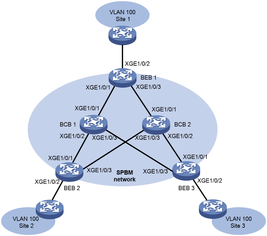
Network requirements
Deploy an SPBM network as shown in Figure 10.
Use I-SID 1000 to extend VLAN 100 across customer sites 1, 2, and 3. Configure I-SID 1000, as shown in Table 5.
Table 5 SPBM service requirements
|
Item |
Requirements |
|
B-VLAN |
VLAN 10 |
|
ECT algorithm index |
3 |
|
Multicast replication |
Tandem replication |
Configuration procedure
1. Configure basic SPBM parameters:
# Create VLAN 100 and B-VLAN 10.
<BEB1> system-view
[BEB1] vlan 100
[BEB1-vlan100] quit
[BEB1] vlan 10
[BEB1-vlan10] quit
# Configure MST region parameters on BEB 1. Make sure B-VLAN 10 is mapped to MSTI 4092.
[BEB1] stp region-configuration
[BEB1-mst-region] region-name spbm
[BEB1-mst-region] instance 4092 vlan 10
[BEB1-mst-region] active region-configuration
[BEB1-mst-region] quit
# Enable SPBM both globally and on the provider network ports on BEB 1, and assign the provider network ports to VLAN 10.
[BEB1] spbm
[BEB1-spbm] quit
[BEB1] interface ten-gigabitethernet 1/0/1
[BEB1-Ten-GigabitEthernet1/0/1] spbm enable
[BEB1-Ten-GigabitEthernet1/0/1] port link-type trunk
[BEB1-Ten-GigabitEthernet1/0/1] port trunk permit vlan 10
[BEB1-Ten-GigabitEthernet1/0/1] quit
[BEB1] interface ten-gigabitethernet 1/0/3
[BEB1-Ten-GigabitEthernet1/0/3] spbm enable
[BEB1-Ten-GigabitEthernet1/0/3] port link-type trunk
[BEB1-Ten-GigabitEthernet1/0/3] port trunk permit vlan 10
[BEB1-Ten-GigabitEthernet1/0/3] quit
# Repeat the previous steps to configure the MST parameters and SPBM feature on all other BEBs and BCBs. (Details not shown.)
|
|
NOTE: On BCBs, you must enable SPBM on all the ports in the SPBM network. |
2. Map B-VLAN 10 to ECT algorithm 3:
# Map B-VLAN 10 to ECT algorithm 3 on BEB 1.
[BEB1] spbm
[BEB1-spbm] ect 3 b-vlan 10
[BEB1-spbm] quit
# Repeat the previous step to map B-VLAN 10 to ECT algorithm 3 on all other BEBs and BCBs. (Details not shown.)
3. Configure the Ethernet service instance for VLAN 100 on the customer edge port on BEB 1:
# Enable L2VPN.
[BEB1] l2vpn enable
# Create an SPB VSI (I-SID 1000) for VLAN 100 traffic.
[BEB1] vsi test
[BEB1-vsi-test] spb i-sid 1000
# Assign B-VLAN 10 to the SPB VSI.
[BEB1-vsi-test-1000] b-vlan 10
# Enable tandem multicast replication mode for the SPB VSI.
[BEB1-vsi-test-1000] multicast replicate-mode tandem
[BEB1-vsi-test-1000] quit
[BEB1-vsi-test] quit
# Create Ethernet service instance 1, assign VLAN 100 to this instance, and map the service instance to the SPB VSI.
[BEB1] interface ten-gigabitethernet 1/0/2
[BEB1-Ten-GigabitEthernet1/0/2] port link-type trunk
[BEB1-Ten-GigabitEthernet1/0/2] port trunk permit vlan 100
[BEB1-Ten-GigabitEthernet1/0/2] service-instance 1
[BEB1-Ten-GigabitEthernet1/0/2-srv1] encapsulation s-vid 100
[BEB1-Ten-GigabitEthernet1/0/2-srv1] xconnect vsi test
[BEB1-Ten-GigabitEthernet1/0/2-srv1] quit
[BEB1-Ten-GigabitEthernet1/0/2] quit
[BEB1] quit
# Repeat the previous step to configure the Ethernet service instance for VLAN 100 on all other BEBs. (Details not shown.)
Verifying the configuration
Use Table 6 to verify that all the SPBM nodes have correctly established ISIS-SPB adjacencies and collected topology data, and that the BEBs have correctly established PWs.
|
BEB |
B-MAC |
BCB |
B-MAC |
|
BEB 1 |
0011.2200.1101 |
BCB 1 |
0011.2200.1401 |
|
BEB 2 |
0011.2200.1201 |
BCB 2 |
0011.2200.1501 |
|
BEB 3 |
0011.2200.1301 |
|
|
1. Verify the configuration on BEBs (for example, BEB 1):
# Verify that the BEB has ISIS-SPB adjacencies with all its neighbors.
<BEB1> display spbm peer
Peer information for SPBM
-------------------------
System ID Port Circuit ID State Holdtime
0011.2200.1401 XGE1/0/1 1 Up 28s
0011.2200.1501 XGE1/0/3 1 Up 28s
The output shows that BEB 1 has adjacencies with BCB 1 and BCB 2.
# Verify that ISIS-SPB can collect complete SPBM topology data.
<BEB1> display spbm lsdb
Database information for SPBM
-----------------------------
LSP ID: * - Local LSP
LSP ID Seq Num Checksum Holdtime Length Overload
-------------------------------------------------------------------------------
0011.2200.1101.00-00* 0x00000002 0x7bf8 1180 93 0
0011.2200.1101.00-01* 0x00000003 0xe7c8 1180 108 0
0011.2200.1201.00-00 0x00000002 0xa9e 1186 93 0
0011.2200.1201.00-01 0x00000003 0x7e23 1186 108 0
0011.2200.1301.00-00 0x00000002 0xc9e 1186 93 0
0011.2200.1301.00-01 0x00000003 0x7a21 1186 108 0
0011.2200.1401.00-00 0x00000002 0xa23b 1190 93 0
0011.2200.1401.00-01 0x00000003 0xdfb6 1190 108 0
0011.2200.1501.00-00 0x00000002 0xa23b 1190 93 0
0011.2200.1501.00-01 0x00000003 0xdfb6 1190 108 0
# Verify that the BEB has unicast PWs to all other BEBs.
<BEB1> display spbm unicast-pw
System ID I-SID B-MAC B-VLAN Port
0011.2200.1201 1000 0011-2200-1201 10 XGE1/0/1
0011.2200.1301 1000 0011-2200-1301 10 XGE1/0/1
# Verify that the BEB has a multicast PW on B-VLAN 10 for I-SID 1000.
<BEB1> display spbm multicast-pw
System ID I-SID MAC address B-VLAN Port
0011.2200.1101 1000 0306-4000-03e8 10 XGE1/0/1
# Verify that the BEB has created unicast FDB entries for reaching other SPBM neighbors.
<BEB1> display spbm unicast-fdb
Flags: E-Egress T-Transit
System ID B-MAC B-VLAN Flags Port
0011.2200.1201 0011-2200-1201 10 T XGE1/0/1
0011.2200.1301 0011-2200-1301 10 T XGE1/0/1
0011.2200.1401 0011-2200-1401 10 T XGE1/0/1
0011.2200.1501 0011-2200-1501 10 T XGE1/0/3
# Verify that the BEB has created multicast FDB entries with itself as the multicast source.
<BEB1> display spbm multicast-fdb
Flags: E-Egress T-Transit
System ID MAC address B-VLAN Flags Port
0011.2200.1101 0306-4000-03e8 10 T XGE1/0/1
0011.2200.1201 0306-4001-03e8 10 E N/A
0011.2200.1301 0306-4002-03e8 10 E N/A
2. Verify the configuration on BCBs (for example, BCB 1):
# Verify that the BCB has ISIS-SPB adjacencies with all its neighbors.
<BCB1> display spbm peer
Peer information for SPBM
-------------------------
System ID Port Circuit ID State Holdtime
0011.2200.1101 XGE1/0/1 1 Up 26s
0011.2200.1201 XGE1/0/2 1 Up 26s
0011.2200.1301 XGE1/0/3 1 Up 22s
# Verify that ISIS-SPB can collect complete SPBM topology data.
<BCB1> display spbm lsdb
Database information for SPBM
-----------------------------
LSP ID: * - Local LSP
LSP ID Seq Num Checksum Holdtime Length Overload
-------------------------------------------------------------------------------
0011.2200.1101.00-00 0x00000002 0x7bf8 1180 93 0
0011.2200.1101.00-01 0x00000003 0xe7c8 1180 108 0
0011.2200.1201.00-00 0x00000002 0xa9e 1186 93 0
0011.2200.1201.00-01 0x00000003 0x7e23 1186 108 0
0011.2200.1301.00-00 0x00000002 0xc9e 1186 93 0
0011.2200.1301.00-01 0x00000003 0x7a21 1186 108 0
0011.2200.1401.00-00* 0x00000002 0xa23b 1190 93 0
0011.2200.1401.00-01* 0x00000003 0xdfb6 1190 108 0
0011.2200.1501.00-00 0x00000002 0xa23b 1190 93 0
0011.2200.1501.00-01 0x00000003 0xdfb6 1190 108 0
# Verify that the BCB has created unicast FDB entries for reaching all other SPBM nodes.
<BCB1> display spbm unicast-fdb
Flags: E-Egress T-Transit
System ID B-MAC B-VLAN Flags Port
0011.2200.1101 0011-2200-1101 10 T XGE1/0/1
0011.2200.1201 0011-2200-1201 10 T XGE1/0/2
0011.2200.1301 0011-2200-1301 10 T XGE1/0/3
0011.2200.1501 0011-2200-1501 10 T XGE1/0/1
# Verify that the BCB has created multicast FDB entries for reaching all other SPBM nodes.
<BCB1> display spbm multicast-fdb
Flags: E-Egress T-Transit
System ID MAC address B-VLAN Flags Port
0011.2200.1101 0306-4000-03e8 10 T XGE1/0/2
XGE1/0/3
0011.2200.1201 0306-4001-03e8 10 T XGE1/0/1
XGE1/0/3
0011.2200.1301 0306-4002-03e8 10 T XGE1/0/1
XGE1/0/2
SPBM with head-end replication configuration example
Network requirements
As shown in Figure 11, deploy an SPBM network to meet the following requirements:
· Use I-SID 3001 to extend VLAN 100 across customer sites 1, 2, and 3.
· Use head-end replication (the default) for multicast in the SPBM network.
· Assign B-VLAN 3001 to I-SID 3001.

Configuration procedure
1. Configure BEB 1:
# Create VLAN 100 and B-VLAN 3001.
<BEB1> system-view
[BEB1] vlan 100
[BEB1-vlan100] quit
[BEB1] vlan 3001
[BEB1-vlan3001] quit
# Configure MST region parameters on BEB 1. Make sure B-VLAN 3001 is mapped to MSTI 4092.
[BEB1] stp region-configuration
[BEB1-mst-region] region-name spb
[BEB1-mst-region] instance 4092 vlan 3001
[BEB1-mst-region] active region-configuration
[BEB1-mst-region] quit
# Enable SPBM both globally and on the provider network port on BEB 1. Assign the provider network port to B-VLAN 3001.
[BEB1] spbm
[BEB1-spbm] quit
[BEB1] interface ten-gigabitethernet 1/0/2
[BEB1-Ten-GigabitEthernet1/0/2] port link-type trunk
[BEB1-Ten-GigabitEthernet1/0/2] port trunk permit vlan 3001
[BEB1-Ten-GigabitEthernet1/0/2] spbm enable
[BEB1-Ten-GigabitEthernet1/0/2] quit
# Enable L2VPN.
[BEB1] l2vpn enable
# Create an SPB VSI (I-SID 3001).
[BEB1] vsi test
[BEB1-vsi-test] spb i-sid 3001
# Assign B-VLAN 3001 to the SPB VSI.
[BEB1-vsi-test-3001] b-vlan 3001
[BEB1-vsi-test-3001] quit
[BEB1-vsi-test] quit
# Assign customer network port Ten-GigabitEthernet 1/0/1 to VLAN 100.
[BEB1] interface ten-gigabitethernet 1/0/1
[BEB1-Ten-GigabitEthernet1/0/1] port link-type trunk
[BEB1-Ten-GigabitEthernet1/0/1] port trunk permit vlan 100
# Configure Ethernet service instance 1 to match VLAN 100, and map the service instance to the SPB VSI.
[BEB1-Ten-GigabitEthernet1/0/1] service-instance 1
[BEB1-Ten-GigabitEthernet1/0/1-srv1] encapsulation s-vid 100
[BEB1-Ten-GigabitEthernet1/0/1-srv1] xconnect vsi test
[BEB1-Ten-GigabitEthernet1/0/1-srv1] quit
[BEB1-Ten-GigabitEthernet1/0/1] quit
2. Repeat the previous steps to configure the MST parameters and SPBM feature on BEB 2 and BEB 3. (Details not shown.)
3. Configure the BCB:
# Create B-VLAN 3001.
<BCB> system-view
[BCB] vlan 3001
[BCB-vlan3001] quit
# Configure MST region parameters on the BCB. Make sure B-VLAN 3001 is mapped to MSTI 4092.
[BCB] stp region-configuration
[BCB-mst-region] region-name spb
[BCB-mst-region] instance 4092 vlan 3001
[BCB-mst-region] active region-configuration
[BCB-mst-region] quit
# Enable SPBM both globally and on the provider network ports on the BCB. Assign the provider network ports to B-VLAN 3001.
[BCB] spbm
[BCB-spbm] quit
[BCB] interface ten-gigabitethernet 1/0/1
[BCB-Ten-GigabitEthernet1/0/1] port link-type trunk
[BCB-Ten-GigabitEthernet1/0/1] port trunk permit vlan 3001
[BCB-Ten-GigabitEthernet1/0/1] spbm enable
[BCB-Ten-GigabitEthernet1/0/1] quit
[BCB] interface ten-gigabitethernet 1/0/2
[BCB-Ten-GigabitEthernet1/0/2] port link-type trunk
[BCB-Ten-GigabitEthernet1/0/2] port trunk permit vlan 3001
[BCB-Ten-GigabitEthernet1/0/2] spbm enable
[BCB-Ten-GigabitEthernet1/0/2] quit
Verifying the configuration
Verify the configuration on BEBs (for example, BEB 1).
1. Verify that the BEB has ISIS-SPB adjacency with its neighbor.
[BEB1] display spbm peer
Peer information for SPBM
-------------------------
System ID Port Circuit ID State Holdtime
0000.eeee.0101 XGE1/0/2 2 Up 29s
2. Verify that the BEB has established tunnels to other BEBs.
[BEB1] display l2vpn vsi name test verbose
VSI Name: test
VSI Index : 1
VSI State : Up
MTU : 1500
Bandwidth : Unlimited
Broadcast Restrain : Unlimited
Multicast Restrain : Unlimited
Unknown Unicast Restrain: Unlimited
MAC Learning : Enabled
MAC Table Limit : -
MAC Learning rate : -
Drop Unknown : -
SPB I-SID : 3001
Flooding : Enabled
Statistics : Disabled
VXLAN ID : -
SPB Connections:
BMAC BVLAN Link ID Type
0000-eeee-0141 3001 64 Unicast
0000-9999-0141 3001 65 Unicast
ACs:
AC Link ID State Type
XGE1/0/1 srv1 0 Up Manual
SPBM with tandem replication configuration example
Network requirements
As shown in Figure 12, deploy an SPBM network to meet the following requirements:
· Use I-SID 3001 to extend VLAN 100 across customer sites 1, 2, and 3.
· Use tandem replication for multicast in the SPBM network.
· Assign B-VLAN 3001 to I-SID 3001.
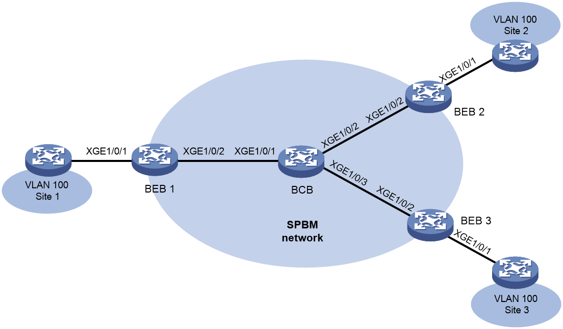
Configuration procedure
1. Configure BEB 1:
# Create VLAN 100 and B-VLAN 3001.
<BEB1> system-view
[BEB1] vlan 100
[BEB1-vlan100] quit
[BEB1] vlan 3001
[BEB1-vlan3001] quit
# Configure MST region parameters on BEB 1. Make sure B-VLAN 3001 is mapped to MSTI 4092.
[BEB1] stp region-configuration
[BEB1-mst-region] region-name spb
[BEB1-mst-region] instance 4092 vlan 3001
[BEB1-mst-region] active region-configuration
[BEB1-mst-region] quit
# Enable SPBM both globally and on the provider network port on BEB 1. Assign the provider network port to B-VLAN 3001.
[BEB1] spbm
[BEB1-spbm] quit
[BEB1] interface ten-gigabitethernet 1/0/2
[BEB1-Ten-GigabitEthernet1/0/2] port link-type trunk
[BEB1-Ten-GigabitEthernet1/0/2] port trunk permit vlan 3001
[BEB1-Ten-GigabitEthernet1/0/2] spbm enable
[BEB1-Ten-GigabitEthernet1/0/2] quit
# Enable L2VPN.
[BEB1] l2vpn enable
# Create an SPB VSI (I-SID 3001).
[BEB1] vsi test
[BEB1-vsi-test] spb i-sid 3001
# Assign B-VLAN 3001 to the SPB VSI.
[BEB1-vsi-test-3001] b-vlan 3001
# Enable tandem multicast replication for the SPB VSI.
[BEB1-vsi-test-3001] multicast replicate-mode tandem
[BEB1-vsi-test-3001] quit
[BEB1-vsi-test] quit
# Assign customer network port Ten-GigabitEthernet 1/0/1 to VLAN 100.
[BEB1] interface ten-gigabitethernet 1/0/1
[BEB1-Ten-GigabitEthernet1/0/1] port link-type trunk
[BEB1-Ten-GigabitEthernet1/0/1] port trunk permit vlan 100
# Configure Ethernet service instance 1 to match VLAN 100, and map the service instance to the SPB VSI.
[BEB1-Ten-GigabitEthernet1/0/1] service-instance 1
[BEB1-Ten-GigabitEthernet1/0/1-srv1] encapsulation s-vid 100
[BEB1-Ten-GigabitEthernet1/0/1-srv1] xconnect vsi test
[BEB1-Ten-GigabitEthernet1/0/1-srv1] quit
[BEB1-Ten-GigabitEthernet1/0/1] quit
2. Repeat the previous steps to configure the MST parameters and SPBM feature on BEB 2 and BEB 3. (Details not shown.)
3. Configure the BCB:
# Create B-VLAN 3001.
<BCB> system-view
[BCB] vlan 3001
[BCB-vlan3001] quit
# Configure MST region parameters on the BCB. Make sure B-VLAN 3001 is mapped to MSTI 4092
[BCB] stp region-configuration
[BCB-mst-region] region-name spb
[BCB-mst-region] instance 4092 vlan 3001
[BCB-mst-region] active region-configuration
[BCB-mst-region] quit
# Enable SPBM both globally and on the provider network ports on the BCB. Assign the provider network ports to B-VLAN 3001.
[BCB] spbm
[BCB-spbm] quit
[BCB] interface ten-gigabitethernet 1/0/1
[BCB-Ten-GigabitEthernet1/0/1] port link-type trunk
[BCB-Ten-GigabitEthernet1/0/1] port trunk permit vlan 3001
[BCB-Ten-GigabitEthernet1/0/1] spbm enable
[BCB-Ten-GigabitEthernet1/0/1] quit
[BCB] interface ten-gigabitethernet 1/0/2
[BCB-Ten-GigabitEthernet1/0/2] port link-type trunk
[BCB-Ten-GigabitEthernet1/0/2] port trunk permit vlan 3001
[BCB-Ten-GigabitEthernet1/0/2] spbm enable
[BCB-Ten-GigabitEthernet1/0/2] quit
Verifying the configuration
Verify the configuration on BEBs (for example, BEB 1).
1. Verify that the BEB has ISIS-SPB adjacency with its neighbor.
[BEB1] display spbm peer
Peer information for SPBM
-------------------------
System ID Port Circuit ID State Holdtime
0000.eeee.0101 XGE1/0/2 2 Up 29s
2. Verify that the BEB has established tunnels to other BEBs.
[BEB1] display l2vpn vsi name test verbose
VSI Name: test
VSI Index : 1
VSI State : Up
MTU : 1500
Bandwidth : Unlimited
Broadcast Restrain : Unlimited
Multicast Restrain : Unlimited
Unknown Unicast Restrain: Unlimited
MAC Learning : Enabled
MAC Table Limit : -
MAC Learning rate : -
Drop Unknown : -
SPB I-SID : 3001
Flooding : Enabled
Statistics : Disabled
VXLAN ID : -
SPB Connections:
BMAC BVLAN Link ID Type
0000-eeee-0141 3001 64 Unicast
0000-9999-0141 3001 65 Unicast
0300-6000-0bb9 3001 - Multicast
ACs:
AC Link ID State Type
XGE1/0/1 srv1 0 Up Manual
The output shows that a multicast tunnel has been established for tandem multicast replication.
ECT migration by changing B-VLAN example
Network requirements
As shown in Figure 13, deploy an SPBM network to meet the following requirements:
· Use I-SID 3001 to extend VLAN 100 across customer sites 1, 2, and 3.
· Move I-SID 3001 from the original ECT algorithm to ECT algorithm 9. Change the B-VLAN from 3001 to 3003 for I-SID 3001.
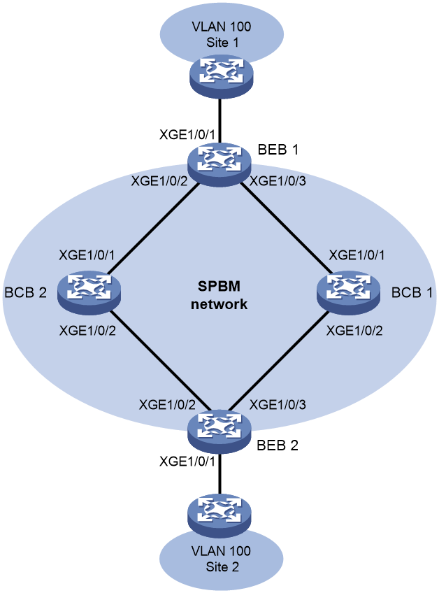
Configuration procedure
1. Configure BEB 1:
# Create VLAN 100, B-VLAN 3001, and B-VLAN 3003.
<BEB1> system-view
[BEB1] vlan 100
[BEB1-vlan100] quit
[BEB1] vlan 3001
[BEB1-vlan3001] quit
[BEB1] vlan 3003
[BEB1-vlan3003] quit
# Configure MST region parameters on BEB 1. Make sure B-VLAN 3001 and B-VLAN 3003 are mapped to MSTI 4092.
[BEB1] stp region-configuration
[BEB1-mst-region] region-name spb
[BEB1-mst-region] instance 4092 vlan 3001 3003
[BEB1-mst-region] active region-configuration
[BEB1-mst-region] quit
# Enable SPBM globally.
[BEB1] spbm
# Map B-VLAN 3003 to ECT algorithm 9.
[BEB1-spbm] ect 9 b-vlan 3003
[BEB1-spbm] quit
# Enable SPBM on the provider network ports on BEB 1. Assign the provider network ports to B-VLAN 3001 and B-VLAN 3003.
[BEB1] interface ten-gigabitethernet 1/0/2
[BEB1-Ten-GigabitEthernet1/0/2] port link-type trunk
[BEB1-Ten-GigabitEthernet1/0/2] port trunk permit vlan 3001 3003
[BEB1-Ten-GigabitEthernet1/0/2] spbm enable
[BEB1-Ten-GigabitEthernet1/0/2] quit
[BEB1] interface ten-gigabitethernet 1/0/3
[BEB1-Ten-GigabitEthernet1/0/3] port link-type trunk
[BEB1-Ten-GigabitEthernet1/0/3] port trunk permit vlan 3001 3003
[BEB1-Ten-GigabitEthernet1/0/3] spbm enable
[BEB1-Ten-GigabitEthernet1/0/3] quit
# Enable L2VPN.
[BEB1] l2vpn enable
# Create an SPB VSI (I-SID 3001).
[BEB1] vsi test
[BEB1-vsi-test] spb i-sid 3001
# Assign B-VLAN 3001 to the SPB VSI.
[BEB1-vsi-test-3001] b-vlan 3001
[BEB1-vsi-test-3001] quit
[BEB1-vsi-test] quit
# Assign customer network port Ten-GigabitEthernet 1/0/1 to VLAN 100.
[[BEB1] interface ten-gigabitethernet 1/0/1
[BEB1-Ten-GigabitEthernet1/0/1] port link-type trunk
[BEB1-Ten-GigabitEthernet1/0/1] port trunk permit vlan 100
# Configure Ethernet service instance 1 to match VLAN 100, and map the service instance to the SPB VSI.
[BEB1-Ten-GigabitEthernet1/0/1] service-instance 1
[BEB1-Ten-GigabitEthernet1/0/1-srv1] encapsulation s-vid 100
[BEB1-Ten-GigabitEthernet1/0/1-srv1] xconnect vsi test
[BEB1-Ten-GigabitEthernet1/0/1-srv1] quit
[BEB1-Ten-GigabitEthernet1/0/1] quit
2. Repeat the previous steps to configure the MST parameters and SPBM feature on BEB 2. (Details not shown.)
3. Configure BCB 1:
# Create B-VLAN 3001 and B-VLAN 3003.
<BCB1> system-view
[BCB1] vlan 3001
[BCB1-vlan3001] quit
[BCB1] vlan 3003
[BCB1-vlan3003] quit
# Configure MST region parameters on BCB 1. Make sure B-VLAN 3001 and B-VLAN 3003 are mapped to MSTI 4092.
[BCB1] stp region-configuration
[BCB1-mst-region] region-name spb
[BCB1-mst-region] instance 4092 vlan 3001 3003
[BCB1-mst-region] active region-configuration
[BCB1-mst-region] quit
# Enable SPBM globally.
[BCB1] spbm
# Map B-VLAN 3003 to ECT algorithm 9.
[BCB1-spbm] ect 9 b-vlan 3003
[BCB1-spbm] quit
# Enable SPBM on the provider network ports on BCB 1. Assign the provider network ports to B-VLAN 3001 and B-VLAN 3003.
[BCB1] interface ten-gigabitethernet 1/0/1
[BCB1-Ten-GigabitEthernet1/0/1] port link-type trunk
[BCB1-Ten-GigabitEthernet1/0/1] port trunk permit vlan 3001 3003
[BCB1-Ten-GigabitEthernet1/0/1] spbm enable
[BCB1-Ten-GigabitEthernet1/0/1] quit
[BCB1] interface ten-gigabitethernet 1/0/2
[BCB1-Ten-GigabitEthernet1/0/2] port link-type trunk
[BCB1-Ten-GigabitEthernet1/0/2] port trunk permit vlan 3001 3003
[BCB1-Ten-GigabitEthernet1/0/2] spbm enable
[BCB1-Ten-GigabitEthernet1/0/2] quit
4. Configure BCB 2 in the same way you configure BCB 1. (Details not shown.)
5. Perform ECT migration:
# On BEB 1, change the B-VLAN to 3003 for the SPB VSI test.
[BEB1] vsi test
[BEB1-vsi-test] spb i-sid 3001
[BEB1-vsi-test-3001] b-vlan 3003
[BEB1-vsi-test-3001] quit
[BEB1-vsi-test] quit
# Configure BEB 2 in the same way you configure BEB 1. (Details not shown.)
Verifying the configuration
1. Before you perform ECT migration, verify the configuration on BEBs (for example, BEB 1):
# Verify that the BEB has ISIS-SPB adjacencies with all its neighbors.
[BEB1] display spbm peer
Peer information for SPBM
-------------------------
System ID Port Circuit ID State Holdtime
0000.eeee.0101 XGE1/0/2 2 Up 29s
0000.eeee.0141 XGE1/0/3 3 Up 29s
# Verify that the BEB has established a tunnel to the other BEB.
[BEB1] display l2vpn vsi name test verbose
VSI Name: test
VSI Index : 1
VSI State : Up
MTU : 1500
Bandwidth : Unlimited
Broadcast Restrain : Unlimited
Multicast Restrain : Unlimited
Unknown Unicast Restrain: Unlimited
MAC Learning : Enabled
MAC Table Limit : -
MAC Learning rate : -
Drop Unknown : -
SPB I-SID : 3001
Flooding : Enabled
Statistics : Disabled
VXLAN ID : -
SPB Connections:
BMAC BVLAN Link ID Type
0000-9999-0141 3001 65 Unicast
ACs:
AC Link ID State Type
XGE1/0/1 srv1 0 Up Manual
# Verify that I-SID 3001 uses B-VLAN 3001 to transmit customer traffic.
[BEB1] display spbm ect-migration i-sid 3001
ECT B-VLAN T R
00-80-c2-01 3001 1 1
2. After you perform ECT migration, verify that I-SID 3001 uses B-VLAN 3003 to transmit customer traffic (for example, on BEB 1):
[BEB1] display spbm ect-migration i-sid 3001
ECT B-VLAN T R
00-80-c2-09 3003 0 1
ECT migration by changing ECT algorithm example
Network requirements
As shown in Figure 14, move I-SID 1000 from the original ECT algorithm to ECT algorithm 2. Change the B-VLAN for I-SID 1000 from VLAN 10 to VLAN 20.

Configuration procedure
This example uses BEB 1 to show the configuration procedure. You can configure other SPBM devices in the same way you configure BEB 1.
1. Configure the new B-VLAN (VLAN 20 in this example):
Perform this task on all BEBs and BCBs in the SPBM network.
# Create VLAN 20.
<BEB1> system-view
[BEB1] vlan 20
[BEB1-vlan20] quit
# Map B-VLAN 20 to MSTI 4092, and activate the change.
[BEB1] stp region-configuration
[BEB1-mst-region] instance 4092 vlan 20
[BEB1-mst-region] active region-configuration
[BEB1-mst-region] quit
# Assign the provider network ports to VLAN 20.
[BEB1] interface ten-gigabitethernet 1/0/1
[BEB1-Ten-GigabitEthernet1/0/1] port trunk permit vlan 20
[BEB1-Ten-GigabitEthernet1/0/1] quit
[BEB1] interface ten-gigabitethernet 1/0/3
[BEB1-Ten-GigabitEthernet1/0/3] port trunk permit vlan 20
[BEB1-Ten-GigabitEthernet1/0/3] quit
2. Map B-VLAN 20 to ECT algorithm 2.
Perform this task on all BEBs and BCBs in the SPBM network.
[BEB1] spbm
[BEB1-spbm] ect 2 b-vlan 20
[BEB1-spbm] quit
3. Assign B-VLAN 20 to I-SID 1000.
Perform this task on all BEBs in the SPBM network.
[BEB1] vsi test
[BEB1-vsi-test] spb i-sid 1000
[BEB1-vsi-test-1000] b-vlan 20
[BEB1-vsi-test-1000] quit
[BEB1-vsi-test] quit
[BEB1] quit
Verifying the configuration
1. Verify the configuration and forwarding states during ECT migration:
¡ On BEBs (BEB 1 in this example):
# Verify the ECT migration configuration for I-SID 1000.
<BEB1> display spbm ect-migration i-sid 1000
ECT B-VLAN T R
00-80-c2-02 20 1 1
00-80-c2-03 10 1 1
The output shows that I-SID 1000 is migrating from ECT algorithm 3 to ECT algorithm 2. During this period, both B-VLAN 10 and B-VLAN 20 can transmit traffic.
# Verify that the BEB has set up unicast PWs for I-SID 1000 on both B-VLANs 10 and 20.
<BEB1> display spbm unicast-pw
System ID I-SID B-MAC B-VLAN Port
0011.2200.1201 1000 0011-2200-1201 10 XGE1/0/1
20 XGE1/0/3
0011.2200.1301 1000 0011-2200-1301 10 XGE1/0/1
20 XGE1/0/3
# Verify that the BEB still uses the original multicast PW established on B-VLAN 10 for I-SID 1000.
<BEB1> display spbm multicast-pw
System ID I-SID MAC address B-VLAN Port
0011.2200.1101 1000 0306-4000-03e8 10 XGE1/0/1
# Verify that the BEB has created unicast FDB entries in both B-VLAN 10 and B-VLAN 20 for I-SID 1000.
<BEB1> display spbm unicast-fdb
Flags: E-Egress T-Transit
System ID B-MAC B-VLAN Flags Port
0011.2200.1201 0011-2200-1201 10 T XGE1/0/1
0011.2200.1201 0011-2200-1201 20 T XGE1/0/3
0011.2200.1301 0011-2200-1301 10 T XGE1/0/1
0011.2200.1301 0011-2200-1301 20 T XGE1/0/3
0011.2200.1401 0011-2200-1401 10 T XGE1/0/1
0011.2200.1401 0011-2200-1401 20 T XGE1/0/1
0011.2200.1501 0011-2200-1501 10 T XGE1/0/3
0011.2200.1501 0011-2200-1501 20 T XGE1/0/3
# Verify that the BEB has created multicast FDB entries in both B-VLAN 10 and B-VLAN 20 for I-SID 1000.
<BEB1> display spbm multicast-fdb
Flags: E-Egress T-Transit
System ID MAC address B-VLAN Flags Port
0011.2200.1101 0306-4000-03e8 10 T XGE1/0/1
0011.2200.1101 0306-4000-03e8 20 T XGE1/0/3
0011.2200.1201 0306-4001-03e8 10 E N/A
0011.2200.1201 0306-4001-03e8 20 E N/A
0011.2200.1301 0306-4002-03e8 10 E N/A
0011.2200.1301 0306-4002-03e8 20 E N/A
¡ On BCBs (BCB 1 in this example):
# Verify that the BCB has created unicast FDB entries in both B-VLANs 10 and 20 for I-SID 1000.
<BCB1> display spbm unicast-fdb
Flags: E-Egress T-Transit
System ID B-MAC B-VLAN Flags Port
0011.2200.1101 0011-2200-1101 10 T XGE1/0/1
0011.2200.1101 0011-2200-1101 20 T XGE1/0/1
0011.2200.1201 0011-2200-1201 10 T XGE1/0/2
0011.2200.1201 0011-2200-1201 20 T XGE1/0/2
0011.2200.1301 0011-2200-1301 10 T XGE1/0/3
0011.2200.1301 0011-2200-1301 20 T XGE1/0/3
0011.2200.1501 0011-2200-1501 10 T XGE1/0/1
0011.2200.1501 0011-2200-1501 20 T XGE1/0/3
# Verify that the BCB has created multicast FDB entries in both B-VLANs 10 and 20 for I-SID 1000.
<BCB1> display spbm multicast-fdb
Flags: E-Egress T-Transit
System ID MAC address B-VLAN Flags Port
0011.2200.1101 0306-4000-03e8 10 T XGE1/0/2
XGE1/0/3
0011.2200.1101 0306-4000-03e8 20 T XGE1/0/2
XGE1/0/3
0011.2200.1201 0306-4001-03e8 10 T XGE1/0/1
XGE1/0/3
0011.2200.1201 0306-4001-03e8 20 T XGE1/0/1
XGE1/0/3
0011.2200.1301 0306-4002-03e8 10 T XGE1/0/1
XGE1/0/2
0011.2200.1301 0306-4002-03e8 20 T XGE1/0/1
XGE1/0/2
2. Verify the configuration and forwarding states after ECT migration is complete:
¡ On BEBs (BEB 1 in this example):
# Verify that I-SID 1000 has migrated from ECT algorithm 3 to ECT algorithm 2. SPBM has removed the mapping between I-SID 1000 and B-VLAN 10.
<BEB1> display spbm ect-migration i-sid 1000
ECT B-VLAN T R
00-80-c2-02 20 1 1
# Verify that the BEB has unicast PWs only on B-VLAN 20 for I-SID 1000. The BEB has removed the PWs set up on B-VLAN 10 for I-SID 1000.
<BEB1> display spbm unicast-pw
System ID I-SID B-MAC B-VLAN Port
0011.2200.1201 1000 0011-2200-1201 20 XGE1/0/3
0011.2200.1301 1000 0011-2200-1301 20 XGE1/0/3
# Verify that the BEB has set up a multicast PW on B-VLAN 20 for I-SID 1000. The original multicast PW has been removed.
<BEB1> display spbm multicast-pw
System ID I-SID MAC address B-VLAN Port
0011.2200.1101 1000 0306-4000-03e8 20 XGE1/0/3
# Verify that the BEB has unicast FDB entries for both B-VLANs 10 and 20. The BEB still has unicast FDB entries for B-VLAN 10 because B-VLAN 10 is still on MSTI 4092.
<BEB1> display spbm unicast-fdb
Flags: E-Egress T-Transit
System ID B-MAC B-VLAN Flags Port
0011.2200.1201 0011-2200-1201 10 T XGE1/0/1
0011.2200.1201 0011-2200-1201 20 T XGE1/0/3
0011.2200.1301 0011-2200-1301 10 T XGE1/0/1
0011.2200.1301 0011-2200-1301 20 T XGE1/0/3
0011.2200.1401 0011-2200-1401 10 T XGE1/0/1
0011.2200.1401 0011-2200-1401 20 T XGE1/0/1
0011.2200.1501 0011-2200-1501 10 T XGE1/0/3
0011.2200.1501 0011-2200-1501 20 T XGE1/0/3
# Verify that the BEB has multicast FDB entries only in B-VLAN 20.
<BEB1> display spbm multicast-fdb
Flags: E-Egress T-Transit
System ID MAC address B-VLAN Flags Port
0011.2200.1101 0306-4000-03e8 20 T XGE1/0/3
0011.2200.1201 0306-4001-03e8 20 E N/A
0011.2200.1301 0306-4002-03e8 20 E N/A
¡ On BCBs (BCB 1 in this example):
# Verify that the BCB has unicast FDB entries in both B-VLANs 10 and 20 for I-SID 1000.
<BCB> display spbm unicast-fdb
Flags: E-Egress T-Transit
System ID B-MAC B-VLAN Flags Port
0011.2200.1101 0011-2200-1101 10 T XGE1/0/1
0011.2200.1101 0011-2200-1101 20 T XGE1/0/1
0011.2200.1201 0011-2200-1201 10 T XGE1/0/2
0011.2200.1201 0011-2200-1201 20 T XGE1/0/2
0011.2200.1301 0011-2200-1301 10 T XGE1/0/3
0011.2200.1301 0011-2200-1301 20 T XGE1/0/3
0011.2200.1501 0011-2200-1501 10 T XGE1/0/1
0011.2200.1501 0011-2200-1501 20 T XGE1/0/3
# Verify that the BCB has multicast FDB entries only in B-VLAN 20 for I-SID 1000.
<BCB> display spbm multicast-fdb
Flags: E-Egress T-Transit
System ID MAC address B-VLAN Flags Port
0011.2200.1101 0306-4000-03e8 20 T XGE1/0/2
XGE1/0/3
0011.2200.1201 0306-4001-03e8 20 T XGE1/0/1
XGE1/0/3
0011.2200.1301 0306-4002-03e8 20 T XGE1/0/1
XGE1/0/2
SPBM NSR configuration example
Network requirements
As shown in Figure 15, deploy an SPBM network to meet the following requirements:
· Use I-SID 1000 to extend VLAN 100 across customer sites 1 and 2.
· Use tandem replication for multicast in the SPBM network.
· Assign B-VLAN 10 to I-SID 1000. Map B-VLAN 10 to ECT algorithm 3.
· Enable NSR for SPBM on the BCB.
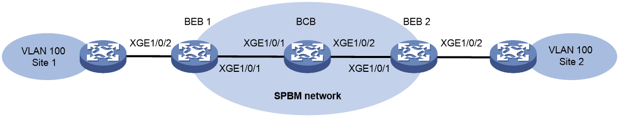
Table 7 B-MACs
|
BEB |
B-MAC |
BCB |
B-MAC |
|
BEB 1 |
0011.2200.1101 |
BCB |
0011.2200.1401 |
|
BEB 2 |
0011.2200.1201 |
|
|
Configuration procedure
1. Configure the MST parameters and SPBM feature on BEB 1:
# Configure MST region parameters. Make sure B-VLAN 10 is mapped to MSTI 4092.
<BEB1> system-view
[BEB1] vlan 10
[BEB1-vlan10] quit
[BEB1] stp region-configuration
[BEB1-mst-region] instance 4092 vlan 10
[BEB1-mst-region] region-name spbm
[BEB1-mst-region] active region-configuration
[BEB1-mst-region] quit
# Enable SPBM both globally and on the provider network port Ten-GigabitEthernet 1/0/1. Assign the provider network port to B-VLAN 10.
[BEB1] spbm
[BEB1-spbm] quit
[BEB1] interface ten-gigabitethernet 1/0/1
[BEB1-Ten-GigabitEthernet1/0/1] spbm enable
[BEB1-Ten-GigabitEthernet1/0/1] port link-type trunk
[BEB1-Ten-GigabitEthernet1/0/1] port trunk permit vlan 10
[BEB1-Ten-GigabitEthernet1/0/1] quit
# Map B-VLAN 10 to ECT algorithm 3.
[BEB1] spbm
[BEB1-spbm] ect 3 b-vlan 10
[BEB1-spbm] quit
2. Configure the MST parameters and SPBM feature on BEB 2 and the BCB in the same way you configure BEB 1. (Details not shown.)
3. Configure the customer-side settings on BEB 1:
# Enable L2VPN.
[BEB1] l2vpn enable
# Create an SPB VSI (I-SID 1000).
[BEB1] vsi test
[BEB1-vsi-test] spb i-sid 1000
# Assign B-VLAN 10 to the SPB VSI.
[BEB1-vsi-test-1000] b-vlan 10
# Enable tandem multicast replication for the SPB VSI.
[BEB1-vsi-test-1000] multicast replicate-mode tandem
[BEB1-vsi-test-1000] quit
[BEB1-vsi-test] quit
# Assign customer network port Ten-GigabitEthernet 1/0/2 to VLAN 100.
[BEB1] interface ten-gigabitethernet 1/0/2
[BEB1-Ten-GigabitEthernet1/0/2] port link-type trunk
[BEB1-Ten-GigabitEthernet1/0/2] port trunk permit vlan 100
# Configure Ethernet service instance 1 to match VLAN 100, and map the service instance to the SPB VSI.
[BEB1-Ten-GigabitEthernet1/0/2] service-instance 1
[BEB1-Ten-GigabitEthernet1/0/2-srv1] encapsulation s-vid 100
[BEB1-Ten-GigabitEthernet1/0/2-srv1] xconnect vsi test
[BEB1-Ten-GigabitEthernet1/0/2-srv1] quit
[BEB1] quit
4. Configure the customer-side settings on BEB 2 in the same way you configure BEB 1. (Details not shown.)
5. Enable NSR for SPBM on the BCB.
<BCB> system-view
[BCB] spbm
[BCB-spbm] non-stop-routing
[BCB-spbm] quit
Verifying the configuration
1. Trigger an active/standby switchover on the BCB. (Details not shown.)
2. Verify that the BEBs are unaware of the ongoing active/standby switchover:
# Verify that the BEB has adjacency with the BCB. This example uses BEB 1.
<BEB1> display spbm peer
Peer information for SPBM
-------------------------
System ID Port Circuit ID State Holdtime
0011.2200.1401 XGE1/0/1 1 Up 28s
# Verify that the network topology information has not changed on the BEB.
<BEB1> display spbm lsdb
Database information for SPBM
-----------------------------
LSP ID: * - Local LSP
LSP ID Seq Num Checksum Holdtime Length Overload
-------------------------------------------------------------------------------
0011.2200.1101.00-00* 0x00000002 0x7bf8 1180 93 0
0011.2200.1201.00-00 0x00000002 0xa9e 1186 93 0
0011.2200.1401.00-00 0x00000002 0xa23b 1190 93 0
# Verify that the unicast MAC-in-MAC tunnel has not changed between the BEBs.
<BEB1> display spbm unicast-pw
System ID I-SID B-MAC B-VLAN Port
0011.2200.1201 1000 0011-2200-1201 10 XGE1/0/1
# Verify that the multicast MAC-in-MAC tunnel has not changed between the BEBs.
<BEB1> display spbm multicast-pw
System ID I-SID MAC address B-VLAN Port
0011.2200.1101 1000 0306-4000-03e8 10 XGE1/0/1
# Verify that the unicast routes have not changed on the BEB.
<BEB1> display spbm unicast-fdb
Flags: E-Egress T-Transit
System ID B-MAC B-VLAN Flags Port
0011.2200.1201 0011-2200-1201 10 T XGE1/0/1
0011.2200.1401 0011-2200-1401 10 T XGE1/0/1
# Verify that the multicast routes have not changed on the BEB.
<BEB1> display spbm multicast-fdb
Flags: E-Egress T-Transit
System ID MAC address B-VLAN Flags Port
0011.2200.1101 0306-4000-03e8 10 T XGE1/0/1
0011.2200.1201 0306-4001-03e8 10 E N/A
