- Table of Contents
-
- 04-Layer 3—IP Services Configuration Guide
- 00-Preface
- 01-ARP configuration
- 02-IP addressing configuration
- 03-DHCP configuration
- 04-DNS configuration
- 05-IP forwarding basics configuration
- 06-Fast forwarding configuration
- 07-Adjacency table configuration
- 08-IRDP configuration
- 09-IP performance optimization configuration
- 10-UDP helper configuration
- 11-IPv6 basics configuration
- 12-DHCPv6 configuration
- 13-IPv6 fast forwarding configuration
- 14-Tunneling configuration
- 15-GRE configuration
- 16-HTTP redirect configuration
- Related Documents
-
| Title | Size | Download |
|---|---|---|
| 08-IRDP configuration | 72.34 KB |
Contents
Configuring IRDP
The term "router" in this chapter refers to a routing-capable device.
The term "host" in this chapter refers to the host that supports IRDP. For example, a host that runs the Linux operating system.
Overview
ICMP Router Discovery Protocol (IRDP), an extension of the ICMP, is independent of any routing protocol. It allows hosts to discover the IP addresses of neighboring routers that can act as default gateways to reach devices on other IP networks.
IRDP enables hosts to track dynamic changes in router availability and requires a minimal amount of manual configuration.
IRDP operation
IRDP uses the following types of ICMP messages:
· Router advertisement (RA)—Sent by a router to advertise IP addresses (including the primary and secondary IP addresses) and preference.
· Router solicitation (RS)—Sent by a host to request the IP addresses of routers on the subnet.
An interface with IRDP enabled periodically broadcasts or multicasts an RA message to advertise its IP addresses. A receiving host adds the IP addresses to its routing table, and selects the IP address with the highest preference as the default gateway.
When a host attached to the subnet starts up, the host multicasts an RS message to request immediate advertisements. If the host does not receive any advertisements, it retransmits the RS several times. If the host does not discover the IP addresses of neighboring routers because of network problems, the host can still discover them from periodic RAs.
IRDP allows hosts to discover neighboring routers, but it does not suggest the best route to a destination. If a host sends a packet to a router that is not the best next hop, the host will receive an ICMP redirect message from the router.
Basic concepts
Preference of an IP address
Every IP address advertised in RAs has a preference value. A larger preference value represents a higher preference. The IP address with the highest preference is selected as the default gateway address.
You can specify the preference for IP addresses to be advertised on a router interface.
An address with the minimum preference value (-2147483648) will not be used as a default gateway address.
Lifetime of an IP address
An RA contains a lifetime field that specifies the lifetime of advertised IP addresses. If the host does not receive a new RA for an IP address within the address lifetime, the host removes the route entry.
All the IP addresses advertised by an interface have the same lifetime.
Advertising interval
A router interface with IRDP enabled sends out RAs randomly between the minimum and maximum advertising intervals. This mechanism prevents the local link from being overloaded by a large number of RAs sent simultaneously from routers.
As a best practice, shorten the advertising interval on a link that suffers high packet loss rates.
Destination address of RAs
An RA uses either of the following destination IP addresses:
· Broadcast address 255.255.255.255.
· Multicast address 224.0.0.1, which identifies all hosts on the local link.
By default, the destination IP address of an RA is the broadcast address. If all listening hosts in a local area network support IP multicast, specify 224.0.0.1 as the destination IP address.
Proxy-advertised IP addresses
By default, an interface advertises its primary and secondary IP addresses. You can specify IP addresses of other gateways for an interface to proxy-advertise.
Protocols and standards
RFC 1256: ICMP Router Discovery Messages
Configuration procedure
To configure IRDP:
|
Step |
Command |
Remarks |
|
1. Enter system view. |
system-view |
N/A |
|
2. Enter interface view. |
interface interface-type interface-number |
The interface can be any Layer 3 interface except the Loopback interface. |
|
3. Enable IRDP on the interface. |
ip irdp |
By default, IRDP is disabled. After IRDP is enabled on an interface, the IRDP configuration takes effect, and the device sends RA messages out of the interface. |
|
4. (Optional.) Specify the preference of advertised primary and secondary IP addresses on the interface. |
ip irdp preference preference-value |
The default preference is 0. |
|
5. (Optional.) Set the lifetime of IP addresses to be advertised. |
ip irdp lifetime lifetime-value |
The default lifetime is 1800 seconds. The lifetime applies to all advertised IP addresses, including proxy-advertised IP addresses on the interface. The lifetime cannot be shorter than the maximum advertising interval. |
|
6. (Optional.) Set the maximum and minimum advertising intervals. |
ip irdp interval max-interval [ min-interval ] |
By default, the maximum interval is 600 seconds, and the minimum interval is 3/4 of the maximum interval. |
|
7. (Optional.) Specify the multicast address 224.0.0.1 as the destination IP address of RAs. |
ip irdp multicast |
By default, RAs use the broadcast address 255.255.255.255 as the destination IP address. |
|
8. (Optional.) Specify a proxy-advertised IP address and its preference. |
ip irdp address ip-address preference-value |
Repeat this step to specify multiple proxy-advertised IP addresses. By default, no IP address is specified. You can specify a maximum of four proxy-advertised IP addresses on an interface. |
IRDP configuration example
Network requirements
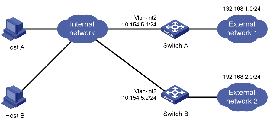
As shown in Figure 1, Host A and Host B that run Linux support IRDP, and they are in the internal network. Switch A and Switch B act as the egress routers and connect to external networks 192.168.1.0/24 and 192.168.2.0/24, respectively.
Configure Switch A as the default gateway for the hosts. Make sure Switch A has routes to reach both External network 1 and External network 2, so packets to these external networks can be correctly routed.
Configuration procedure
1. Configure Switch A:
# Configure a route for Switch A to reach External network 2. (Details not shown.)
# Specify an IP address for VLAN-interface 2.
<SwitchA> system-view
[SwitchA] interface vlan-interface 2
[SwitchA-Vlan-interface2] ip address 10.154.5.1 24
# Enable IRDP on VLAN-interface 2.
[SwitchA-Vlan-interface2] ip irdp
# Specify preference 1000 for advertised IP addresses on VLAN-interface 2.
[SwitchA-Vlan-interface2] ip irdp preference 1000
# Specify the multicast address 224.0.0.1 as the destination IP address for RAs sent by VLAN-interface 2.
[SwitchA-Vlan-interface2] ip irdp multicast
# Specify the IP address 192.168.1.0 and preference 400 for VLAN-interface 2 to proxy-advertise.
[SwitchA-Vlan-interface2] ip irdp address 192.168.1.0 400
2. Configure Switch B:
# Specify an IP address for VLAN-interface 2.
<SwitchB> system-view
[SwitchB] interface vlan-interface 2
[SwitchB-Vlan-interface2] ip address 10.154.5.2 24
# Enable IRDP on VLAN-interface 2.
[SwitchB-Vlan-interface2] ip irdp
# Specify preference 500 for advertised IP addresses on VLAN-interface 2.
[SwitchB-Vlan-interface2] ip irdp preference 500
# Specify the multicast address 224.0.0.1 as the destination IP address for RAs sent by VLAN-interface 2.
[SwitchB-Vlan-interface2] ip irdp multicast
# Specify the IP address 192.168.2.0 and preference 400 for VLAN-interface 2 to proxy-advertise.
[SwitchB-Vlan-interface2] ip irdp address 192.168.2.0 400
Verifying the configuration
# Display the routing table for Host A.
[HostA@localhost ~]$ netstat -rne
Kernel IP routing table
Destination Gateway Genmask Flags Metric Ref Use Iface
10.154.5.0 0.0.0.0 255.255.255.0 U 0 0 0 eth1
192.168.1.0 0.0.0.0 255.255.255.0 U 0 0 0 eth1
192.168.2.0 0.0.0.0 255.255.255.0 U 0 0 0 eth1
0.0.0.0 10.154.5.1 0.0.0.0 UG 0 0 0 eth1
The output shows that the default route on Host A points to IP address 10.154.5.1, and Host A has routes to 192.168.1.0/24 and 192.168.2.0/24.
# Display the routing table for Host B.
[HostB@localhost ~]$ netstat -rne
Kernel IP routing table
Destination Gateway Genmask Flags Metric Ref Use Iface
10.154.5.0 0.0.0.0 255.255.255.0 U 0 0 0 eth1
192.168.1.0 0.0.0.0 255.255.255.0 U 0 0 0 eth1
192.168.2.0 0.0.0.0 255.255.255.0 U 0 0 0 eth1
0.0.0.0 10.154.5.1 0.0.0.0 UG 0 0 0 eth1
The output shows that the default route on Host B points to IP address 10.154.5.1, and Host B has routes to 192.168.1.0/24 and 192.168.2.0/24.