- Table of Contents
- Related Documents
-
| Title | Size | Download |
|---|---|---|
| 02-Logging In to the Switching Engine Configuration | 771.55 KB |
Contents
Logging in to the switching engine through OAP
Configuring the management IP address of the OAP software system
Configuring the management IP address of the OAP software system on the switching engine
Configuring the management IP address of the OAP software system of the access controller engine·
Resetting the OAP software system
Telnet login authentication modes
Configuring none authentication for telnet login
Configuring password authentication for telnet login
Configuring scheme authentication for telnet login
Configuring common settings for VTY user interfaces (optional)
Configuring the switching engine to log in to a telnet server as a telnet client
Configuring the SSH client to log in to the SSH server
Displaying and maintaining CLI login
Displaying and maintaining web login
Configuring login control over telnet users
Configuring source IP-based login control over telnet users
Configuring source and destination IP-based login control over telnet users
Configuring source MAC-based login control over telnet users
Source MAC-based login control configuration example
Configuring source IP-based login control over NMS users
Configuring source IP-based login control over NMS users
Source IP-based login control over NMS users configuration example
Configuring source IP-based login control over web users
Configuring source IP-based login control over web users
Source IP-based login control over web users configuration example
Login methods
This chapter includes these sections:
|
|
NOTE: · The term "switch" or "device" in this chapter refers to the switching engine on a WX3000E wireless switch. · The WX3000E series comprises WX3024E and WX3010E wireless switches. · The port numbers in this chapter are for illustration only. |
Login methods
You can log in to the switching engine in the following ways.
Table 1 Login methods
|
Login method |
Default state |
||
|
By default, you can log in to the switching engine through OAP. The authentication mode is None (no username or password required), and the user privilege level is 3. |
|||
|
By default, you can log in to the switching engine through Telnet. The username and password are both admin, the IP address of the switching engine is 192.168.0.101, and the user privilege level is 3. |
|||
|
By default, you cannot log in to a switching engine through SSH. To do so, log in to the switching engine through OAP, and complete the following configuration: · Enable the SSH function and configure SSH attributes. · Configure the IP address of the network management port or VLAN interface, and make sure that your switching engine and the SSH client can reach each other (by default, the IP address of VLAN-interface 1 is 192.168.0.101.). · Configure the authentication mode of VTY login users as scheme (password by default). · Configure the user privilege level of VTY login users (0 by default). |
|||
|
By default, you can log in to the switching engine through web. The username and password are both admin, the IP address of the switching engine is 192.168.0.101, and the user privilege level is 3. |
|||
|
By default, you cannot log in to the switching engine through a network management station (NMS). To do so, log in to the switching engine through OAP, and complete the following configuration: · Configure the IP address of the VLAN interface, and make sure the switching engine and the NMS can reach each other (by default, the IP address of VLAN-interface 1 is 192.168.0.101.). · Configure SNMP basic parameters. |
|||
User interface overview
A user interface, also called line, enables you to manage and monitor sessions between the terminal and the switching engine when you log in to the switching engine through OAP, Telnet, or SSH.
A single user interface corresponds to a single user interface view where you can configure a set of parameters, such as whether to authenticate users at login, whether to redirect the requests to another device, and the user privilege level after login.
When the user logs in through a user interface, the connection follows these parameter settings, implementing centralized management of various sessions.
At present, the system supports the following CLI configuration methods:
· Local configuration through OAP
· Local or remote configuration through Telnet or SSH
The CLI configuration methods correspond to the following types of user interfaces:
· AUX user interface: Manages and monitors users that log in through OAP.
· VTY (virtual type terminal) user interface: Used to manage and monitor users that log in via VTY. A VTY port is a logical terminal line used for Telnet or SSH access.
Users and user interfaces
At a time, only one user can use a user interface. The configuration made in a user interface view applies to any user logged in to that user interface. For example, if user A logs in through OAP, the configuration in the AUX port user interface view applies to user A. If user A logs in through VTY 1, the configuration in the VTY 1 user interface view applies to user A.
The WX3000E series wireless switch switching engine supports one AUX user interface, and 16 Ethernet interfaces, so the switching engine supports multiple user interfaces. These user interfaces do not associate with specific users. When a user initiates a connection request, the system automatically assigns an idle user interface with the smallest number to the user based on the login method. During login, the configuration in the user interface view takes effect. The user interface varies depending on the login method and login time.
Numbering user interfaces
User interfaces are numbered by using absolute numbering or relative numbering.
Absolute numbering
Absolute numbering identifies a user interface or a group of different types of user interfaces. The specified user interfaces are numbered from number 0 with a step of 1 and in the sequence of AUX, and VTY user interfaces. You can use the display user-interface command without any parameters to view supported user interfaces and their absolute numbers.
Relative numbering
Relative numbering allows you to specify a user interface or a group of user interfaces of a specific type. The number format is “user interface type + number”. The following rules of relative numbering apply:
· The AUX port is numbered 0.
· VTYs are numbered from 0 in the ascending order, with a step of 1.
This chapter includes these sections:
· Overview
· Displaying and maintaining CLI login
|
|
NOTE: · The term "switch" or "device" in this chapter refers to the switching engine on a WX3000E wireless switch. · The WX3000E series comprises WX3024E and WX3010E wireless switches. · The port numbers in this chapter are for illustration only. |
Overview
The CLI enables you to interact with the switching engine by typing text commands. At the CLI, you can instruct your switching engine to perform a given task by typing a text command and then pressing Enter to submit it to your switching engine. Compared with the graphical user interface (GUI) where you can use a mouse to perform configuration, the CLI allows you to input more information in one command line.
You can log in to the switching engine at the CLI through OAP, telnet, or SSH.
· By default, you can log in to the switching engine through OAP without any authentication, which introduces security problems.
· By default, you cannot log in to the switching engine through telnet, SSH, or modem, so you cannot remotely manage and maintain the switching engine.
Therefore, you need to perform configurations to increase switching engine security and manageability.
Logging in through OAP
As an open software and hardware system, Open Application Architecture (OAA) provides a set of complete standard software and hardware interfaces. The third party vendors can develop products with special functions. These products can be compatible with each other as long as they conform to the OAA interface standards. Therefore the functions of single network product can be expanded and the users can get more benefits.
Open Application Platform (OAP) is a physical platform developed based on OAA. It can be an independent network device, or a board or program used as an extended part of a device. An OAP runs an independent operating system. You can load software such as security and voice in the operating system as needed.
Logging in to the switching engine through OAP
You can log in to the access controller engine through the console port on the device and you can redirect to the operating system of the switching engine through OAP by performing the following operation. The terminal display interface will be switched from the command line interface on the access controller engine to the operating interface of the operating system of the switching engine. You can then manage the system and application software on the switching engine. To return to the command line interface (CLI) on the access controller engine after the switch, press Ctrl+K.
Follow these steps to log in to the switching engine through OAP:
|
To do… |
Use the command… |
Remarks |
|
Log in to the switching engine through OAP |
oap connect slot 0 |
Required Available in user view |
Configuring the management IP address of the OAP software system
In the OAA system of the device, the access controller engine and the switching engine integrate together and function as one device. For the snmp UDP Domain-based network management station (NMS), however, the access controller engine and the switching engine are independent SNMP agents. Physically, two agents are on the same managed object; while logically, they belong to two different systems, and they manage their own MIB objects on the access controller engine and the switching engine separately. Therefore, when you use the NMS to manage the access controller engine and the switching engine on the same interface, you must first obtain the management IP addresses of the two SNMP agents and obtain the link relationship between them, and then you can access the two agents.
|
|
CAUTION: Before configuring the management IP address of the OAP software system, you must configure the same IP address at the engine side where the OAP software system resides; otherwise, the NMS cannot access the OAP software system by using the configured management IP address. |
Follow these steps to configure the management IP address of the OAP software system:
|
To do… |
Use the command… |
Remarks |
|
Enter system view |
system-view |
— |
|
Configure the management IP address of an OAP software system |
oap management-ip ip-address slot 0 |
Optional The management IP address of switching engine is 192.168.0.101/24 and the management IP address of access controller engine is 192.168.0.100/24 by default. |
Configuring the management IP address of the OAP software system on the switching engine
|
|
NOTE: To distinguish between the access controller engine and the switching engine, device_LSW represents a switching engine and device to represents an access controller engine. |
1. Configure the management IP address of the OAP software system on the switching engine side.
<device_LSW> system-view
[device_LSW] interface vlan-interface 1
[device_LSW-Vlan-interface1] ip address 192.168.0.100 24
Press Ctrl+K to return to the command line operating interface of the access controller engine.
2. Configure the management IP address of the SNMP agent on the access controller engine.
<device> system-view
[device] oap management-ip 192.168.0.100 slot 0
Configuring the management IP address of the OAP software system of the access controller engine
1. Configure the management IP address of the OAP software system on the access controller engine side.
<device> system-view
[device] interface Vlan-interface 1
[device-Vlan-interface1] ip address 192.168.0.101 24
2. Log in to the switching engine, and configure the management IP address of the SNMP agent on the switching engine.
<device> oap connect slot 0
Connected to OAP!
<device_LSW> system-view
[device_LSW] oap management-ip 192.168.0.101 slot 0
Resetting the OAP software system
If the operating system works abnormally or is under other anomalies, you can reset the OAP software system.
Follow these steps to reset the OAP software system:
|
To do… |
Use the command… |
Remarks |
|
Reset the OAP software system |
oap reboot slot 0 |
Required Available in user view |
|
|
CAUTION: The reset operation may cause data loss and service interruption. Therefore, before resetting the OAP software system, you need to save the data on the operating system to avoid service interruption and hardware data loss. |
Logging in through telnet
Introduction
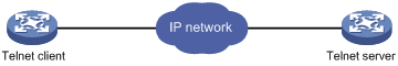
The switching engine supports telnet. You can telnet to the switching engine to remotely manage and maintain it, as shown in Figure 1.
The following table shows the configuration requirements of telnet login.
|
Object |
Requirements |
|
Telnet server |
Configure the IP address of the VLAN interface, and make sure the telnet server and client can reach each other. |
|
Configure the authentication mode and other settings |
|
|
Telnet client |
Run the telnet client program. |
|
Obtain the IP address of the VLAN interface on the server |
By default, the switching engine is enabled with the telnet client and telnet server functions.
· On the switching engine that serves as the telnet client, you can log in to a telnet server to perform operations on the server.
· On the switching engine that serves as the telnet server, you can configure the authentication mode and user privilege level for telnet users. By default, the username and password are both admin, the IP address of the switching engine is 192.168.0.101, and the user privilege level is 3.
This section includes these topics:
· Telnet login authentication modes
· Configuring none authentication for telnet login
· Configuring password authentication for telnet login
· Configuring scheme authentication for telnet login
· Configuring common settings for VTY user interfaces (optional)
· Configuring the switching engine to log in to a telnet server as a telnet client
Telnet login authentication modes
The following authentication modes are available for telnet login: none, password, and scheme.
· none—Requires no username and password at the next login through telnet. This mode is insecure.
· password—Requires password authentication at the next login through telnet. Keep your password. If you lose your password, log in to the switching engine through OAP to view or modify the password.
· scheme—Requires username and password authentication at the next login through telnet. Authentication falls into local authentication and remote authentication. To use local authentication, configure a local user and related parameters. To use remote authentication, configure the username and password on the remote authentication server. For more information about authentication modes and parameters, see the Security Configuration Guide. Keep your username and password.
The following table lists telnet login configurations for different authentication modes.
|
Authentication mode |
Configuration |
Remarks |
||
|
None |
Configure not to authenticate users |
For more information, see “Configuring none authentication for telnet login.” |
||
|
Password |
Configure to authenticate users by using the local password |
For more information, see “Configuring password authentication for telnet login.” |
||
|
Set the local password |
||||
|
Scheme |
Configure the authentication scheme |
For more information, see “Configuring scheme authentication for telnet login.” |
||
|
Select an authentication scheme |
Remote AAA authentication |
Configure a RADIUS/HWTACACS scheme |
||
|
Configure the AAA scheme used by the domain |
||||
|
Configure the username and password on the AAA server |
||||
|
Local authentication |
Configure the authentication username and password |
|||
|
Configure the AAA scheme used by the domain as local |
||||
Configuring none authentication for telnet login
Configuration prerequisites
You have logged in to the switching engine.
By default, you can log in to the switching engine through OAP without authentication and have user privilege level 3 after login. For more information, see “Logging in through OAP.”
Configuration procedure
Follow these steps to configure none authentication for telnet login:
|
To do… |
Use the command… |
Remarks |
|
Enter system view |
system-view |
— |
|
Enable telnet |
telnet server enable |
Required By default, the telnet service is enabled. |
|
Enter one or multiple VTY user interface views |
user-interface vty first-number [ last-number ] |
— |
|
Specify the none authentication mode |
authentication-mode none |
Required By default, authentication mode for VTY user interfaces is password. |
|
Configure the command level for login users on the current user interfaces |
user privilege level level |
Required By default, the default command level is 0 for VTY user interfaces. |
|
Configure common settings for VTY user interfaces |
— |
Optional See “Configuring common settings for VTY user interfaces (optional).” |
When you log in to the switching engine through telnet again, perform the following steps:
· You enter the VTY user interface.
Configuring password authentication for telnet login
Configuration prerequisites
You have logged in to the switching engine.
By default, you can log in to the switching engine through OAP without authentication and have user privilege level 3 after login. For more information, see “Logging in through OAP.”
Configuration procedure
Follow these steps to configure password authentication for telnet login:
|
To do… |
Use the command… |
Remarks |
|
Enter system view |
system-view |
— |
|
Enable telnet |
telnet server enable |
Required By default, the telnet service is enabled. |
|
Enter one or multiple VTY user interface views |
user-interface vty first-number [ last-number ] |
— |
|
Specify the password authentication mode |
authentication-mode password |
Required By default, authentication mode for VTY user interfaces is password. |
|
Set the local password |
set authentication password { cipher | simple } password |
Required By default, no local password is set. |
|
Configure the user privilege level for login users |
user privilege level level |
Required 0 by default. |
|
Configure common settings for VTY user interfaces |
— |
Optional See “Configuring common settings for VTY user interfaces (optional).” |
When you log in to the switching engine through telnet again, perform the following steps:
· You are required to enter the login password. A prompt such as <H3C> appears after you enter the correct password and press Enter.
Configuring scheme authentication for telnet login
Configuration prerequisites
You have logged in to the switching engine.
By default, you can log in to the switching engine through OAP without authentication and have user privilege level 3 after login. For more information, see “Logging in through OAP.”
Configuration procedure
Follow these steps to configure scheme authentication for telnet login
|
To do… |
Use the command… |
Remarks |
|
|
Enter system view |
system-view |
— |
|
|
Enable telnet |
telnet server enable |
Required By default, the telnet service is disabled. |
|
|
Enter one or multiple VTY user interface views |
user-interface vty first-number [ last-number ] |
— |
|
|
Specify the scheme authentication mode |
authentication-mode scheme |
Required Whether local, RADIUS, or HWTACACS authentication is adopted depends on the configured AAA scheme. By default, local authentication is adopted. |
|
|
Enable command authorization |
command authorization |
Optional By default, command authorization is not enabled. · By default, the command level depends on the user privilege level. A user is authorized a command level not higher than the user privilege level. With command authorization enabled, the command level for a login user is determined by both the user privilege level and AAA authorization. If a user executes a command of the corresponding command level, the authorization server checks whether the command is authorized. If yes, the command can be executed. · Before enabling command authorization, configure AAA authorization and AAA server. |
|
|
Enable command accounting |
command accounting |
Optional By default, command accounting is disabled. The accounting server does not record the commands executed by users. · Command accounting allows the HWTACACS server to record all executed commands that are supported by the switching engine, regardless of the command execution result. This helps control and monitor user operations on the switching engine. If command accounting is enabled and command authorization is not enabled, every executed command is recorded on the HWTACACS server. If both command accounting and command authorization are enabled, only the authorized and executed commands are recorded on the HWTACACS server. · Before enabling command accounting, configure AAA accounting and AAA server. |
|
|
Exit to system view |
quit |
— |
|
|
Configure the authentication mode |
Enter the default ISP domain view |
domain domain-name |
Optional By default, the AAA scheme is local. If you specify the local AAA scheme, perform the configuration concerning local user as well. If you specify an existing scheme by providing the radius-scheme-name argument, perform the following configuration as well: · For RADIUS and HWTACACS configuration, see the Security Configuration Guide. · Configure the username and password on the AAA server. (For more information, see the Security Configuration Guide.) |
|
Specify the AAA scheme to be applied to the domain |
authentication default { hwtacacs-scheme hwtacacs-scheme-name [ local ] | local | none | radius-scheme radius-scheme-name [ local ] } |
||
|
Exit to system view |
quit |
||
|
Create a local user and enter local user view |
local-user user-name |
By default, no local user exists. |
|
|
Set the local password |
password { cipher | simple } password |
Required By default, no local password is set. |
|
|
Specifies the command level of the local user |
authorization-attribute level level |
Optional By default, the command level is 0. |
|
|
Specify the service type for the local user |
service-type telnet |
Required By default, no service type is specified. |
|
|
Exit to system view |
quit |
— |
|
|
Configure common settings for VTY user interfaces |
— |
Optional See “Configuring common settings for VTY user interfaces (optional).” |
|
After you enable command authorization or command accounting, you need to perform the following configuration to make the function take effect:
· Create a HWTACACS scheme, and specify the IP address of the authorization/accounting server and other authorization/accounting parameters.
· Reference the created HWTACACS scheme in the ISP domain.
For more information, see the Security Configuration Guide.
When users adopt the scheme mode to log in to the switching engine, the level of the commands that the users can access depends on the user privilege level defined in the AAA scheme.
· When the AAA scheme is local, the user privilege level is defined by the authorization-attribute level level command.
· When the AAA scheme is RADIUS or HWTACACS, the user privilege level is configured on the RADIUS or HWTACACS server.
For more information about AAA, RADIUS, and HWTACACS, see the Security Configuration Guide.
When you log in to the switching engine through telnet again:
· You are required to enter the login username and password. A prompt such as <H3C> appears after you enter the correct username and password and press Enter.
· If “All user interfaces are used, please try later!” is displayed, it means the current login users exceed the maximum number. Please try later.
Configuring common settings for VTY user interfaces (optional)
Follow these steps to configure Common settings for VTY user interfaces:
|
To do… |
Use the command… |
Remarks |
|
|
Enter system view |
system-view |
— |
|
|
Enable display of copyright information |
copyright-info enable |
Optional Enabled by default. |
|
|
Specify the source IPv4 address or source interface for sending telnet packets when the device serves as a telnet client |
telnet client source { ip ip-address | interface interface –number } |
Optional By default, no source IPv4 address or source interface for sending telnet packets is specified. |
|
|
Create a VLAN interface and enter its view |
interface vlan-interface vlan-interface-id |
Required If a VLAN interface already exists, the command enters the VLAN interface view. |
|
|
Specify an IP address for the VLAN interface |
ip address ip-address { mask | mask-length } |
Required By default, the IP address of the VLAN interface is 192.168.0.101. |
|
|
Return to system view |
quit |
— |
|
|
Enter one or multiple VTY user interface views |
user-interface vty first-number [ last-number ] |
— |
|
|
Enable the terminal service |
shell |
Optional Enabled by default. |
|
|
Enable the current user interface(s) to support either Telnet, SSH, or both of them |
protocol inbound { all | ssh | telnet } |
Optional By default, both protocols are supported. The configuration takes effect next time you log in. |
|
|
Define a shortcut key for terminating tasks |
escape-key { default | character } |
Optional By default, you can press Ctrl+C to terminate a task. |
|
|
Configure the type of terminal display |
terminal type { ansi | vt100 } |
Optional By default, the terminal display type is ANSI. |
|
|
Set the maximum number of lines to be displayed on the next screen |
screen-length screen-length |
Optional By default, the next screen displays 24 lines. A value of 0 disables the function. |
|
|
Set the size of history command buffer |
history-command max-size value |
Optional By default, the buffer saves 10 history commands. |
|
|
Set the idle-timeout timer |
idle-timeout minutes [ seconds ] |
Optional The default idle-timeout is 10 minutes for all user interfaces. The system automatically terminates the user’s connection if there is no information interaction between the switching engine and the user in timeout time. Setting idle-timeout to 0 disables the timer. |
|
|
Specify a command to be automatically executed when a user logs in to the current user interface |
auto-execute command command |
Optional By default, command auto-execution is disabled. The system automatically executes the specified command when a user logs in to the user interface, and ends the user connection after the command is executed. If the command triggers another task, the system does not end the user connection until the task is completed. A telnet command is usually specified to enable the user to automatically telnet to the specified switching engine. |
|
|
|
CAUTION: The auto-execute command command may disable you from configuring the system through the user interface to which the command is applied. Before configuring the command and saving the configuration (by using the save command), make sure that you can access the switching engine through VTY or AUX interface to remove the configuration when a problem occurs. |
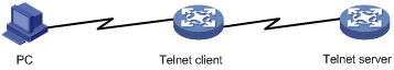
Configuring the switching engine to log in to a telnet server as a telnet client
Configuration prerequisites
You have logged in to the switching engine.
By default, you can log in to the switching engine through OAP without authentication and have user privilege level 3 after login. For more information, see “Logging in through OAP.”
Figure 2 Telnet from the switching engine (telnet client) to another device (telnet server)
|
|
NOTE: If the telnet client port and the telnet server port that connect them are not in the same subnet, make sure that the two devices can reach each other. |
Configuration procedure
|
To do… |
Use the command… |
Remarks |
|
Configure the switching engine to log in to a telnet server as a telnet client |
telnet remote-host [ service-port ] [ [ source { interface interface-type interface-number | ip ip-address } ] ] |
Required Available in user view |
Logging in through SSH
Introduction
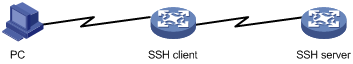
Secure Shell (SSH) offers an approach to log into a remote device securely. By providing encryption and strong authentication, it protects devices against attacks such as IP spoofing and plain text password interception. The switching engine supports SSH, and you can log in to the switching engine through SSH to remotely manage and maintain the switching engine, as shown in Figure 3.
The following table shows the configuration requirements of SSH login.
|
Object |
Requirements |
|
SSH server |
Configure the IP address of the VLAN interface, and make sure the SSH server and client can reach each other. |
|
Configure the authentication mode and other settings. |
|
|
SSH client |
Run the SSH client program. |
|
Obtain the IP address of the VLAN interface on the server. |
By default, the switching engine is disabled with the SSH server function and enabled with the SSH client function.
· On the switching engine that serves as the SSH client, you can log in to an SSH server to perform operations on the server.
· On the switching engine that serves as the SSH server, you can configure the authentication mode and user level for SSH users. Before you can log in to the switching engine through SSH, you need to log in to the switching engine through OAP, enable the SSH server function, and configure the authentication mode, user level, and common settings.
This section includes these topics:
· Configuring the SSH client to log in to the SSH server
Configuring the SSH server
Configuration prerequisites
You have logged in to the switching engine, and want to log in to the switching engine through SSH in the future.
By default, you can log in to the switching engine through OAP without authentication and have user privilege level 3 after login. For more information, see “Logging in through OAP.”
Configuration procedure
Follow these steps to configure the switching engine that serves as an SSH server:
|
To do… |
Use the command… |
Remarks |
|
Enter system view |
system-view |
— |
|
Create local key pair(s) |
public-key local create { dsa | rsa } |
Required By default, no local key pair(s) are created. |
|
Enable SSH server |
ssh server enable |
Required By default, SSH server is disabled. |
|
Enter one or more VTY user interface views |
user-interface vty first-number [ last-number ] |
— |
|
Specify the scheme authentication mode |
authentication-mode scheme |
Required By default, authentication mode for VTY user interfaces is password. |
|
Enable the current user interface to support either Telnet, SSH, or both of them |
protocol inbound { all | ssh | telnet } |
Optional By default, both protocols are supported. |
|
Create a local user and enter local user view |
local-user user-name |
Required By default, no local user exists. |
|
Set the local password |
password { cipher | simple } password |
Required By default, no local password is set. |
|
Specify the command level of the local user |
authorization-attribute level level |
Optional By default, the command level is 0. |
|
Specify the service type for the local user |
service-type ssh |
Required By default, no service type is specified. |
|
Return to system view |
quit |
— |
|
Create an SSH user, and specify the authentication mode for the SSH user |
ssh user username service-type stelnet authentication-type { password | { any | password-publickey | publickey } assign publickey keyname } |
Required By default, no SSH user exists, and no authentication mode is specified. |
|
Configure common settings for VTY user interfaces |
— |
Optional See “Configuring common settings for VTY user interfaces (optional).” |
|
|
NOTE: For more information about SSH and how to configure an SSH client by using publickey, see the Security Configuration Guide. |
Configuring the SSH client to log in to the SSH server
Configuration prerequisites
You have logged in to the switching engine.
By default, you can log in to the switching engine through OAP without authentication and have user privilege level 3 after login. For more information, see “Logging in through OAP.”
Figure 4 Log in to another device from the switching engine
|
|
NOTE: If the SSH client and the SSH server are not in the same subnet, make sure that the two devices can reach each other. |
Configuration procedure
Follow these steps to configure the SSH client to log in to the SSH server:
|
To do… |
Use the command… |
Remarks |
|
Log in to an IPv4 SSH server |
ssh2 server |
Required server is the IPv4 address or host name of the server. Available in user view |
|
Log in to an IPv6 SSH server |
ssh2 ipv6 server |
Required server is the IPv6 address or host name of the server. Available in user view |
Displaying and maintaining CLI login
|
To do… |
Use the command… |
Remarks |
|
Display information about the user interfaces that are being used |
display users [ | { begin | exclude | include } regular-expression ] |
Available in any view |
|
Display information about all user interfaces that the switching engine supports |
display users all [ | { begin | exclude | include } regular-expression ] |
Available in any view |
|
Display user interface information |
display user-interface [ num1 | { aux | vty } num2 ] [ summary ] [ | { begin | exclude | include } regular-expression ] |
Available in any view |
|
Display the configuration of the switching engine when it serves as a telnet client |
display telnet client configuration [ | { begin | exclude | include } regular-expression ] |
Available in any view |
|
Release a specified user interface |
free user-interface { num1 | { aux | vty } num2 } |
Available in user view Multiple users can log in to the system to simultaneously configure the switching engine. You can execute the command to release the connections established on the specified user interfaces. You cannot use this command to release the connection that you are using. |
|
Lock the current user interface |
lock |
Available in user view By default, the current user interface is not locked. |
|
Send messages to the specified user interfaces |
send { all | num1 | { aux | vty } num2 } |
Available in user view |
Web login
This chapter includes these sections:
· Displaying and maintaining web login
|
|
NOTE: · The term "switch" or "device" in this chapter refers to the switching engine on a WX3000E wireless switch. · The WX3000E series comprises WX3024E and WX3010E wireless switches. · The port numbers in this chapter are for illustration only. |
Web login overview
The switching engine provides a built-in web server. It enables you to log in to the web interface of the switching engine from a PC.
By default, you can log in to the switching engine through web. The username and password are both admin, the IP address of the switching engine is 192.168.0.101, and the user privilege level is 3.
The switching engine supports the following web login methods:
· HTTP login—The Hypertext Transfer Protocol (HTTP) is used for transferring web page information across the Internet. It is an application-layer protocol in the TCP/IP protocol suite. The connection-oriented Transport Control Protocol (TCP) is adopted at the transport layer. Currently, the switching engine supports HTTP 1.0.
· HTTPS login—The Secure HTTP (HTTPS) refers to the HTTP protocol that supports the Security Socket Layer (SSL) protocol. HTTPS uses SSL to encrypt the data exchanged between the HTTPS client and the server to ensure data security and integrity. You can define a certificate attribute-based access control policy to allow legal clients to access the switching engine securely and prohibit illegal clients.
The following table shows the configuration requirements of web login.
|
Object |
Requirements |
|
|
Switching engine |
Configure the IP address of the VLAN interface Make sure the switching engine and the PC can reach each other |
|
|
Required to use one approach |
||
|
PC |
Install a web browser |
|
|
Obtain the IP address of the VLAN interface of the switching engine |
||
Configuring HTTP login
Follow these steps to configure HTTP login:
|
To do… |
Use the command… |
Remarks |
|
Enter system view |
system-view |
— |
|
Enable the HTTP service |
ip http enable |
Required Enabled by default. |
|
Configure the HTTP service port number |
ip http port port-number |
Optional 80 by default. If you execute the command multiple times, the last one takes effect. |
|
Associate the HTTP service with an ACL |
ip http acl acl-number |
Optional By default, the HTTP service is not associated with any ACL. Associating the HTTP service with an ACL enables the switching engine to allow only clients permitted by the ACL to access the switching engine. |
|
Create a local user and enter local user view |
local-user user-name |
Required By default, no local user is configured. |
|
Configure a password for the local user |
password { cipher | simple } password |
Required By default, no password is configured for the local user. |
|
Specify the command level of the local user |
authorization-attribute level level |
Required No command level is configured for the local user. |
|
Specify the telnet service type for the local user |
service-type telnet |
Required By default, no service type is configured for the local user. |
|
Exit to system view |
quit |
— |
|
Create a VLAN interface and enter its view |
interface vlan-interface vlan-interface-id |
Required If the VLAN interface already exists, the command enters its view. |
|
Assign an IP address and subnet mask to the VLAN interface |
ip address ip-address { mask | mask-length } |
Required By default, no IP address is assigned to the VLAN interface. |
Configuring HTTPS login
Follow these steps to configure HTTPS login:
|
To do… |
Use the command… |
Remarks |
|
Enter system view |
system-view |
— |
|
Associate the HTTPS service with an SSL server policy |
ip https ssl-server-policy policy-name |
Required By default, the HTTPS service is not associated with any SSL server policy. · If you disable the HTTPS service, the system automatically de-associates the HTTPS service from the SSL service policy. Before re-enabling the HTTPS service, associate the HTTPS service with an SSL server policy first. Any changes to the SSL server policy associated with the HTTP service that is enabled do not take effect. |
|
Enable the HTTPS service |
ip https enable |
Required Disabled by default. Enabling the HTTPS service triggers an SSL handshake negotiation process. During the process, if the local certificate of the switching engine exists, the SSL negotiation succeeds, and the HTTPS service can be started properly. If no local certificate exists, a certificate application process will be triggered by the SSL negotiation. Because the application process takes much time, the SSL negotiation often fails and the HTTPS service cannot be started normally. In that case, you need to execute the ip https enable command multiple times to start the HTTPS service. |
|
Associate the HTTPS service with a certificate attribute-based access control policy |
ip https certificate access-control-policy policy-name |
Optional By default, the HTTPS service is not associated with any certificate-based attribute access control policy. · Associating the HTTPS service with a certificate-based attribute access control policy enables the switching engine to control the access rights of clients. · You must configure the client-verify enable command in the associated SSL server policy. If not, no clients can log in to the switching engine. · The associated SSL server policy must contain at least one permit rule. Otherwise, no clients can log in to the switching engine. For more information about certificate attribute-based access control policies, see the Security Configuration Guide. |
|
Configure the port number of the HTTPS service |
ip https port port-number |
Optional 443 by default. |
|
Associate the HTTPS service with an ACL |
ip https acl acl-number |
Required By default, the HTTPS service is not associated with any ACL. Associating the HTTPS service with an ACL enables the switching engine to allow only clients permitted by the ACL to access the switching engine. |
|
Create a local user and enter local user view |
local-user user-name |
Required By default, no local user is configured. |
|
Configure a password for the local user |
password { cipher | simple } password |
Required By default, no password is configured for the local user. |
|
Specify the command level of the local user |
authorization-attribute level level |
Required By default, no command level is configured for the local user. |
|
Specify the web service type for the local user |
service-type telnet |
Required By default, no service type is configured for the local user. |
|
Exit to system view |
quit |
— |
|
Create a VLAN interface and enter its view |
interface vlan-interface vlan-interface-id |
Required If the VLAN interface already exists, the command enters its view. |
|
Assign an IP address and subnet mask to the VLAN interface |
ip address ip-address { mask | mask-length } |
Required By default, no IP address is assigned to the VLAN interface. |
Displaying and maintaining web login
|
To do… |
Use the command… |
Remarks |
|
Display information about web users |
display web users [ | { begin | exclude | include } regular-expression ] |
Available in any view |
|
Display HTTP state information |
display ip http [ | { begin | exclude | include } regular-expression ] |
Available in any view |
|
Display HTTPS state information |
display ip https [ | { begin | exclude | include } regular-expression ] |
Available in any view |
Web login example
HTTP login example
Network requirements
As shown in Figure 5, the PC is connected to the device over an IP network. The IP address of the Device is 192.168.0.58/24.
Figure 5 Network diagram for configuring HTTP login

Configuration procedure
1. Configuration on the device
# Create VLAN 1, and add interface VLAN-interface 1 on the device that connects to the PC to VLAN 999.
<Sysname> system-view
[Sysname] interface vlan-interface 1
[Sysname-VLAN-interface1] ip address 192.168.0.58 255.255.255.0
[Sysname-VLAN-interface1] quit
# Create a local user named admin, and set the password to admin for the user. Specify the telnet service type for the local user, and set the command level to 3 for this user.
[Sysname] local-user admin
[Sysname-luser-admin] service-type telnet
[Sysname-luser-admin] authorization-attribute level 3
[Sysname-luser-admin] password simple admin
2. Configuration on the PC
# On the PC, run the web browser. Enter the IP address of the device in the address bar. The web login page appears, as shown in Figure 6.
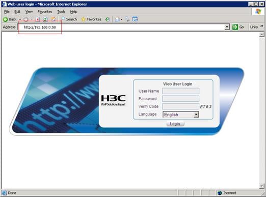
# Type the user name, password, verify code, select English, and click Login. The homepage appears. After login, you can configure device settings through the web interface.
HTTPS login example
Network requirements
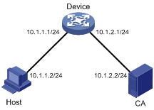
As shown in Figure 7, to prevent unauthorized users from accessing the Device, configure HTTPS login as follows:
· Configure the Device as the HTTPS server, and request a certificate for it.
· The Host acts as the HTTPS client. Request a certificate for it.
In this example, Windows Server acts as the CA. Install Simple Certificate Enrollment Protocol (SCEP) add-on on the CA. The name of the CA that issues certificates to the Device and Host is new-ca.
Before performing the following configuration, make sure that the Device, Host, and CA can reach each other.
Figure 7 Network diagram for configuring HTTPS login
Configuration procedure
1. Configure the device that acts as the HTTPS server
# Configure a PKI entity, configure the common name of the entity as http-server1, and the FQDN of the entity as ssl.security.com.
<Device> system-view
[Device] pki entity en
[Device-pki-entity-en] common-name http-server1
[Device-pki-entity-en] fqdn ssl.security.com
[Device-pki-entity-en] quit
# Create a PKI domain, specify the trusted CA as new-ca, the URL of the server for certificate request as http://10.1.2.2/certsrv/mscep/mscep.dll, authority for certificate request as RA, and the entity for certificate request as en.
[Device] pki domain 1
[Device-pki-domain-1] ca identifier new-ca
[Device-pki-domain-1] certificate request url http://10.1.2.2/certsrv/mscep/mscep.dll
[Device-pki-domain-1] certificate request from ra
[Device-pki-domain-1] certificate request entity en
[Device-pki-domain-1] quit
# Create RSA local key pairs.
[Device] public-key loc al create rsa
# Retrieve the CA certificate from the certificate issuing server.
[Device] pki retrieval-certificate ca domain 1
# Request a local certificate from a CA through SCEP for the device.
[Device] pki request-certificate domain 1
# Create an SSL server policy myssl, specify PKI domain 1 for the SSL server policy, and enable certificate-based SSL client authentication.
[Device] ssl server-policy myssl
[Device-ssl-server-policy-myssl] pki-domain 1
[Device-ssl-server-policy-myssl] client-verify enable
[Device-ssl-server-policy-myssl] quit
# Create a certificate attribute group mygroup1, and configure a certificate attribute rule, specifying that the Distinguished Name (DN) in the subject name includes the string of new-ca.
[Device] pki certificate attribute-group mygroup1
[Device-pki-cert-attribute-group-mygroup1] attribute 1 issuer-name dn ctn new-ca
[Device-pki-cert-attribute-group-mygroup1] quit
# Create a certificate attribute-based access control policy myacp. Configure a certificate attribute-based access control rule, specifying that a certificate is considered valid when it matches an attribute rule in certificate attribute group myacp.
[Device] pki certificate access-control-policy myacp
[Device-pki-cert-acp-myacp] rule 1 permit mygroup1
[Device-pki-cert-acp-myacp] quit
# Associate the HTTPS service with SSL server policy myssl.
[Device] ip https ssl-server-policy myssl
# Associate the HTTPS service with certificate attribute-based access control policy myacp.
[Device] ip https certificate access-control-policy myacp
# Enable the HTTPS service.
[Device] ip https enable
# Create a local user named usera, set the password to 123 for the user, and specify the web service type for the local user.
[Device] local-user usera
[Device-luser-usera] password simple 123
[Device-luser-usera] service-type telnet
2. Configure the host that acts as the HTTPS client
On the host, run the IE browser. In the address bar, enter http://10.1.2.2/certsrv and request a certificate for the host as prompted.
3. Verify the configuration
Enter https://10.1.1.1 in the address bar, and select the certificate issued by new-ca. Then the web login page of the Device appears. On the login page, type the username usera, and password 123 to enter the web management page.
This chapter includes these sections:
|
|
NOTE: · The term "switch" or "device" in this chapter refers to the switching engine on a WX3000E wireless switch. · The WX3000E series comprises WX3024E and WX3010E wireless switches. · The port numbers in this chapter are for illustration only. |
NMS login overview
A Network Management Station (NMS) runs the SNMP client software. It offers a user-friendly interface to facilitate network management. An agent is a program that resides in the switching engine. It receives and handles requests from the NMS. An NMS is a manager in an SNMP enabled network, whereas agents are managed by the NMS. The NMS and agents exchange information through the SNMP protocol. At present, the switching engine supports multiple NMS programs, such as iMC and CAMS.
By default, you cannot log in to the switching engine through NMS. To enable NMS login, log in to the switching engine through OAP and make the configurations described in the following table.
The following table shows the configuration requirements of NMS login.
|
Object |
Requirements |
|
Switching engine |
Configure the IP address of the VLAN interface Make sure the switching engine and the NMS can reach each other |
|
Configure SNMP settings |
|
|
NMS |
Configure the NMS. For more information, see the manual of your NMS |
Configuring NMS login
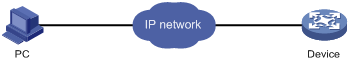
Connect the Ethernet port of the PC to an Ethernet port of VLAN 1 of the switching engine, as shown in Figure 8. Make sure the PC and VLAN 1 interface can reach each other.
Figure 8 Network diagram for configuring NMS login
Follow these steps to configure SNMPv3 settings:
|
To do… |
Use the command… |
Remarks |
|
Enter system view |
system-view |
— |
|
Enable SNMP agent |
snmp-agent |
Optional Disabled by default. You can enable SNMP agent with this command or any command that begins with snmp-agent. |
|
Configure an SNMP group and specify its access right |
snmp-agent group v3 group-name [ authentication | privacy ] [ read-view read-view ] [ write-view write-view ] [ notify-view notify-view ] [ acl acl-number ] |
Required By default, no SNMP group is configured. |
|
Add a user to the SNMP group |
snmp-agent usm-user v3 user-name group-name [ [ cipher ] authentication-mode { md5 | sha } auth-password [ privacy-mode { 3des | aes128 | des56 } priv-password ] ] [ acl acl-number ] |
Required If the cipher keyword is specified, both auth-password and priv-password are cipher text passwords. |
Follow these steps to configure SNMPv1 and SNMPv2c settings:
|
To do… |
Use the command… |
Remarks |
||
|
Enter system view |
system-view |
— |
||
|
Enable SNMP agent |
snmp-agent |
Optional Disabled by default. You can enable SNMP agent with this command or any command that begins with snmp-agent. |
||
|
Create or update MIB view information |
snmp-agent mib-view { excluded | included } view-name oid-tree [ mask mask-value ] |
Optional By default, the MIB view name is ViewDefault and OID is 1. |
||
|
Configure SNMP NMS access right |
Directly |
Configure an SNMP community |
snmp-agent community { read | write } community-name [ acl acl-number | mib-view view-name ]* |
Required Use either approach. The direction configuration approach is for SNMPv1 or SNMPv2c. The community name configured on the NMS should be consistent with the username configured on the agent. The indirect configuration approach is for SNMPv3. |
|
Indirectly |
Configure an SNMP group |
snmp-agent group { v1 | v2c } group-name [ read-view read-view ] [ write-view write-view ] [ notify-view notify-view ] [ acl acl-number ] |
||
|
Add a user to the SNMP group |
snmp-agent usm-user { v1 | v2c } user-name group-name [ acl acl-number ] |
|||
|
|
NOTE: The switching engine supports three SNMP versions: SNMPv1, SNMPv2c and SNMPv3. For more information about SNMP, see the Network Management and Monitoring Configuration Guide. |
NMS login example
In this example, iMC is used as the NMS for illustration.
1. Configuration on the switching engine
# Assign 1.1.1.1/24 for the IP address of switching engine. Make sure the switching engine and the NMS can reach each other. (Configuration steps are omitted.)
# Enter system view.
<Sysname> system-view
# Enable the SNMP agent.
[Sysname] snmp-agent
# Configure an SNMP group.
[Sysname] snmp-agent group v3 managev3group read-view test write-view test
# Add a user to the SNMP group.
[Sysname] snmp-agent usm-user v3 managev3user managev3group
2. Configuration on the NMS
On the PC, start the browser. In the address bar, enter http://192.168.4.112:8080/imc, where 192.168.4.112 is the IP address of the iMC.
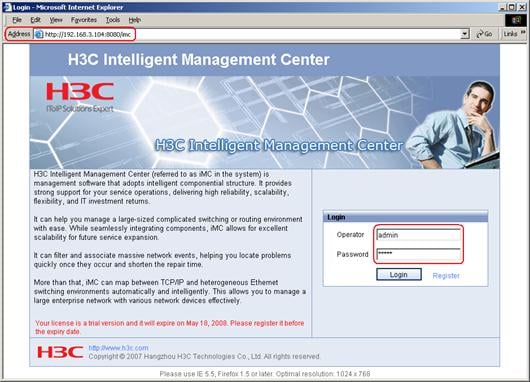
Type the username and password, and then click Login. The iMC homepage appears, as shown in Figure 10.
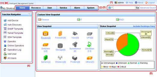
Log in to the iMC and configure SNMP settings for the iMC to find the switching engine. After the switching engine is found, you can manage and maintain the switching engine through the iMC. For example, query switching engine information or configure switching engine parameters.
The SNMP settings on the iMC must be the same as those configured on the switching engine. If not, the switching engine cannot be found or managed by the iMC. See the iMC manuals for more information.
Click Help in the upper right corner of each configuration page to get help information.
This chapter includes these sections:
· Configuring login control over telnet users
· Configuring source IP-based login control over NMS users
· Configuring source IP-based login control over web users
|
|
NOTE: · The term "switch" or "device" in this chapter refers to the switching engine on a WX3000E wireless switch. · The WX3000E series comprises WX3024E and WX3010E wireless switches. · The port numbers in this chapter are for illustration only. |
User login control overview
The switching engine provides the following login control methods.
|
Login Through |
Login control methods |
ACL used |
|
Telnet |
Basic ACL |
|
|
Configuring source and destination IP-based login control over telnet users |
Advanced ACL |
|
|
Configuring source MAC-based login control over telnet users |
Ethernet frame header ACL |
|
|
NMS |
Basic ACL |
Configuring login control over telnet users
Configuration preparation
Before configuration, determine the permitted or denied source IP addresses, source MAC addresses, and destination IP addresses.
Configuring source IP-based login control over telnet users
Basic ACLs match the source IP addresses of packets, so you can use basic ACLs to implement source IP-based login control over telnet users. Basic ACLs are numbered from 2000 to 2999. For more information about ACL, see the ACL and QoS Configuration Guide.
Follow these steps to configure source IP-based login control over telnet users:
|
To do… |
Use the command… |
Remarks |
|
Enter system view |
system-view |
— |
|
Create a basic ACL and enter its view, or enter the view of an existing basic ACL |
acl [ ipv6 ] number acl-number [ match-order { config | auto } ] |
Required By default, no basic ACL exists. |
|
Configure rules for this ACL |
rule [ rule-id ] { permit | deny } [ source { sour-addr sour-wildcard | any } | time-range time-name | fragment | logging ]* |
Required |
|
Exit the basic ACL view |
quit |
— |
|
Enter user interface view |
user-interface [ type ] first-number [ last-number ] |
— |
|
Use the ACL to control user login by source IP address |
acl [ ipv6 ] acl-number { inbound | outbound } |
Required inbound: Filters incoming telnet packets. outbound: Filters outgoing telnet packets. |
Configuring source and destination IP-based login control over telnet users
Advanced ACLs can match both source and destination IP addresses of packets, so you can use advanced ACLs to implement source and destination IP-based login control over telnet users. Advanced ACLs are numbered from 3000 to 3999. For more information about ACL, see the ACL and QoS Configuration Guide.
Follow these steps to configure source and destination IP-based login control over telnet users:
|
To do… |
Use the command… |
Remarks |
|
Enter system view |
system-view |
— |
|
Create an advanced ACL and enter its view, or enter the view of an existing advanced ACL |
acl [ ipv6 ] number acl-number [ match-order { config | auto } ] |
Required By default, no advanced ACL exists. |
|
Configure rules for the ACL |
rule [ rule-id ] { permit | deny } rule-string |
Required |
|
Exit advanced ACL view |
quit |
— |
|
Enter user interface |
user-interface [ type ] first-number [ last-number ] |
— |
|
Use the ACL to control user login by source and destination IP addresses |
acl [ ipv6 ] acl-number { inbound | outbound } |
Required inbound: Filters incoming telnet packets. outbound: Filters outgoing telnet packets. |
Configuring source MAC-based login control over telnet users
Ethernet frame header ACLs can match the source MAC addresses of packets, so you can use Ethernet frame header ACLs to implement source MAC-based login control over telnet users. Ethernet frame header ACLs are numbered from 4000 to 4999. For more information about ACL, see the ACL and QoS Configuration Guide.
Follow these steps to configure source MAC-based login control over telnet users:
|
To do… |
Use the command… |
Remarks |
|
Enter system view |
system-view |
— |
|
Create an Ethernet frame header ACL and enter its view |
acl number acl-number [ match-order { config | auto } ] |
Required By default, no Ethernet frame header ACL exists. |
|
Configure rules for the ACL |
rule [ rule-id ] { permit | deny } rule-string |
Required |
|
Exit the advanced ACL view |
quit |
— |
|
Enter user interface view |
user-interface [ type ] first-number [ last-number ] |
— |
|
Use the ACL to control user login by source MAC address |
acl acl-number inbound |
Required inbound: Filters incoming telnet packets. |
|
|
NOTE: The configuration does not take effect if the telnet client and server are not in the same subnet. |
Source MAC-based login control configuration example
Network requirements
As shown in Figure 11, configure an ACL on the Device to permit only incoming telnet packets sourced from Host A and Host B.
Figure 11 Network diagram for configuring source MAC-based login control
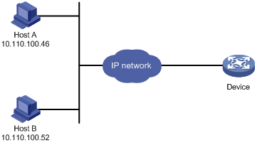
Configuration procedure
# Configure basic ACL 2000, and configure rule 1 to permit packets sourced from Host B, and rule 2 to permit packets sourced from Host A.
<Sysname> system-view
[Sysname] acl number 2000 match-order config
[Sysname-acl-basic-2000] rule 1 permit source 10.110.100.52 0
[Sysname-acl-basic-2000] rule 2 permit source 10.110.100.46 0
[Sysname-acl-basic-2000] quit
# Reference ACL 2000 in user interface view to allow telnet users from Host A and Host B to access the Device.
[Sysname] user-interface vty 0 4
[Sysname-ui-vty0-4] acl 2000 inbound
Configuring source IP-based login control over NMS users
You can log in to the NMS to remotely manage the devices. SNMP is used for communication between the NMS and the agent that resides in the switching engine. By using the ACL, you can control SNMP user access to the switching engine.
Configuration preparation
Before configuration, determine the permitted or denied source IP addresses.
Configuring source IP-based login control over NMS users
Basic ACLs match the source IP addresses of packets, so you can use basic ACLs to implement source IP-based login control over NMS users. Basic ACLs are numbered from 2000 to 2999. For more information about ACL, see the ACL and QoS Configuration Guide.
Follow these steps to configure source IP-based login control over NMS users:
|
To do… |
Use the command… |
Remarks |
|
Enter system view |
system-view |
— |
|
Create a basic ACL and enter its view, or enter the view of an existing basic ACL |
acl [ ipv6 ] number acl-number [ match-order { config | auto } ] |
Required By default, no basic ACL exists. |
|
Create rules for this ACL |
rule [ rule-id ] { permit | deny } [ source { sour-addr sour-wildcard | any } | time-range time-name | fragment | logging ]* |
Required |
|
Exit the basic ACL view |
quit |
— |
|
Associate this SNMP community with the ACL |
snmp-agent community { read | write } community-name [ acl acl-number | mib-view view-name ]* |
Required You can associate the ACL when creating the community, the SNMP group, and the user. For more information about SNMP, see the Network Management and Monitoring Configuration Guide. |
|
Associate the SNMP group with the ACL |
snmp-agent group { v1 | v2c } group-name [ read-view read-view ] [ write-view write-view ] [ notify-view notify-view ] [ acl acl-number ] snmp-agent group v3 group-name [ authentication | privacy ] [ read-view read-view ] [ write-view write-view ] [ notify-view notify-view ] [ acl acl-number ] |
|
|
Associate the user with the ACL |
snmp-agent usm-user { v1 | v2c } user-name group-name [ acl acl-number ] snmp-agent usm-user v3 user-name group-name [ [ cipher ] authentication-mode { md5 | sha } auth-password [ privacy-mode { 3des | aes128 | des56 } priv-password ] ] [ acl acl-number ] |
Source IP-based login control over NMS users configuration example
Network requirements
As shown in Figure 12, configure the device to allow only NMS users from Host A and Host B to access.
Figure 12 Network diagram for configuring source IP-based login control over NMS users

Configuration procedure
# Create ACL 2000, and configure rule 1 to permit packets sourced from Host B, and rule 2 to permit packets sourced from Host A.
<Sysname> system-view
[Sysname] acl number 2000 match-order config
[Sysname-acl-basic-2000] rule 1 permit source 10.110.100.52 0
[Sysname-acl-basic-2000] rule 2 permit source 10.110.100.46 0
[Sysname-acl-basic-2000] quit
# Associate the ACL with the SNMP community and the SNMP group.
[Sysname] snmp-agent community read aaa acl 2000
[Sysname] snmp-agent group v2c groupa acl 2000
[Sysname] snmp-agent usm-user v2c usera groupa acl 2000
Configuring source IP-based login control over web users
You can log in to the web management page of the switching engine through HTTP/HTTPS to remotely manage the devices. By using the ACL, you can control web user access to the switching engine.
Configuration preparation
Before configuration, determine the permitted or denied source IP addresses.
Configuring source IP-based login control over web users
Basic ACLs match the source IP addresses of packets, so you can use basic ACLs to implement source IP-based login control over web users. Basic ACLs are numbered from 2000 to 2999. For more information about ACL, see the ACL and QoS Configuration Guide.
Follow these steps to configure source IP-based login control over web users:
|
To do… |
Use the command… |
Remarks |
|
Enter system view |
system-view |
— |
|
Create a basic ACL and enter its view, or enter the view of an existing basic ACL |
acl [ ipv6 ] number acl-number [ match-order { config | auto } ] |
Required By default, no basic ACL exists. |
|
Create rules for this ACL |
rule [ rule-id ] { permit | deny } [ source { sour-addr sour-wildcard | any } | time-range time-name | fragment | logging ]* |
Required |
|
Exit the basic ACL view |
quit |
— |
|
Associate the HTTP service with the ACL |
ip http acl acl-number |
Required to use one command |
|
Associate the HTTPS service with the ACL |
ip https acl acl-number |
Logging off online web users
Follow the step to log off online web users:
|
To do… |
Use the command… |
Remarks |
|
Log off online web users |
free web-users { all | user-id user-id | user-name user-name } |
Required Available in user interface view |
Source IP-based login control over web users configuration example
Network requirements
As shown in Figure 13, configure the device to allow only web users from Host B to access.
Figure 13 Network diagram for configuring source IP-based login control

Configuration procedure
# Create ACL 2000, and configure rule 1 to permit packets sourced from Host B.
<Sysname> system-view
[Sysname] acl number 2030 match-order config
[Sysname-acl-basic-2030] rule 1 permit source 10.110.100.52 0
# Associate the ACL with the HTTP service so that only web users from Host B are allowed to access the device.
[Sysname] ip http acl 2030