- Table of Contents
-
- 01-Fundamentals Configuration Guide
- 00-Preface
- 01-CLI configuration
- 02-RBAC configuration
- 03-Login management configuration
- 04-FTP and TFTP configuration
- 05-File system management configuration
- 06-Configuration file management configuration
- 07-Software upgrade configuration
- 08-ISSU configuration
- 09-Emergency shell configuration
- 10-Automatic configuration
- 11-Device management configuration
- 12-MDC configuration
- 13-TCL configuration
- 14-License management
- Related Documents
-
| Title | Size | Download |
|---|---|---|
| 12-MDC configuration | 149.28 KB |
Contents
Default MDC and non-default MDCs
Assigning hardware resources to an MDC
Authorizing an MDC to use an interface card
Assigning physical interfaces to an MDC
Specifying a CPU weight for an MDC
Specifying a disk space percentage for an MDC
Specifying a memory space percentage for an MDC
Displaying and maintaining MDCs
MDC configuration example (in standalone mode)
MDC configuration example (in IRF mode)
Configuring MDCs
Overview
The device can be virtualized into multiple logical devices called "multitenant device contexts (MDCs)." Each MDC uses its own interfaces, CPU resources, startup software images, and configuration files, and maintains its own routing table and forwarding table, serves its own users, and is managed by its own administrators. Creating, running, rebooting, or deleting an MDC does not affect the configuration or service of any other MDC. In the user perspective, an MDC is a standalone device.
MDC benefits
· Higher utilization of existing network resources and less hardware upgrade cost—Instead of purchasing new devices, you can configure more MDCs on existing network devices to expand the network. For example, when there are more user groups, you can configure more MDCs and assign them to the user groups. When there are more users in a group, you can assign more interfaces and other resources to the group.
· Lower management and maintenance cost—Management and maintenance of multiple MDCs occur on a single physical device.
· Independence and high security—Each MDC operates like a standalone physical device. It is isolated from other MDCs on the same physical device and cannot directly communicate with them. To allow two MDCs on the same physical device to communicate, you must physically connect a port allocated to one MDC to a port allocated to the other MDC.
MDC applications
As shown in Figure 1, LAN 1, LAN 2, and LAN 3 are three companies' LANs. To provide access service for the three companies, you can deploy a single physical device and configure an MDC for each company. Then, the administrators of each company can log in to only their own MDC to maintain their own network, without affecting any other MDC or network. The effect equals deploying a separate gateway for each company.
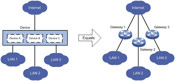
Default MDC and non-default MDCs
A device supporting MDCs is an MDC itself, and it is called the "default MDC" (for example, Device in Figure 1). The default MDC always uses the name Admin and the ID 1. You cannot delete it or change its name or ID.
When you log in to the physical device, you are logged in to the default MDC. Configuring the physical device is configuring the default MDC.
From the default MDC, you can manage the entire physical device, create and delete non-default MDCs (for example, Device A, Device B, and Device C in Figure 1), and assign interfaces, CPU resources, storage space (Flash and CF card), and memory space to non-default MDCs.
No MDCs can be created on a non-default MDC. Administrators of non-default MDCs can only manage and maintain their respective MDCs.
A non-default MDC can use only the resources assigned to it. It cannot use the resources assigned to other MDCs or the remaining resources on the physical device. Resources that are not assigned to any non-default MDC belong to the default MDC.
Unless otherwise stated, the term "MDC" in the following sections refers to a non-default MDC, and all operations in the following sections are performed on the default MDC. For more information about the configurations and services for a non-default MDC, see related manuals.
MDC configuration task list
|
|
IMPORTANT: To configure MDCs for a device that you want to add to an IRF fabric, add the device to the IRF fabric before configuring MDCs for it. After a device joins an IRF fabric, it reboots and loads the master's configuration instead of its own. |
|
Tasks at a glance |
|
(Required.) Creating an MDC |
|
Assigning hardware resources to an MDC: · (Required.) Authorizing an MDC to use an interface card · (Required.) Assigning physical interfaces to an MDC · (Optional.) Specifying a CPU weight for an MDC · (Optional.) Specifying a disk space percentage for an MDC · (Optional.) Specifying a memory space percentage for an MDC |
|
(Required.) Starting an MDC |
|
(Required.) Accessing and managing an MDC |
Although you can assign hardware resources to MDCs before or after you start the MDCs, H3C recommends assigning MDCs resources before starting them.
Creating an MDC
The switch supports creating up to three MDCs. Only an MPU with 4G memory space supports creating MDCs.
To create an MDC:
|
Step |
Command |
Remarks |
|
1. Enter system view. |
system-view |
N/A |
|
2. Create an MDC. |
mdc mdc-name [ id mdc-id ] |
By default, there is a default MDC with the name Admin and the ID 1. The default MDC is system predefined. You do not need to create it, and you cannot delete it. The MDC starts to work after you execute the mdc start command. This command is mutually exclusive with the irf mode enhanced command. For more information about IRF, see IRF Configuration Guide. |
Assigning hardware resources to an MDC
When you create an MDC, the system automatically assigns CPU, storage space, and memory space resources to the MDC to ensure its operation. You can adjust the resource allocations as required.
An MDC needs interfaces to forward packets. However, the system does not automatically assign interfaces to MDCs and you must assign them.
Authorizing an MDC to use an interface card
By default, an MDC can access only the resources on the MPUs; it cannot access any interface cards or resources on the interface cards.
To assign physical interfaces to an MDC, you must authorize the MDC to use the interface cards to which the physical interfaces belong.
To authorize an MDC to use an interface card:
|
Step |
Command |
Remarks |
|
1. Enter system view. |
system-view |
N/A |
|
2. Enter MDC view. |
mdc mdc-name [ id mdc-id ] |
N/A |
|
3. Authorize the MDC to use an interface card. |
· In standalone mode: · In IRF mode: |
By default, all interface cards of the device belong to the default MDC, and a non-default MDC cannot use any interface card. You can authorize multiple MDCs to use the same interface card. |
Assigning physical interfaces to an MDC
By default, all physical interfaces belong to the default MDC, and a non-default MDC has no physical interfaces to use for packet forwarding. To enable a non-default MDC to forward packets, you must assign it interfaces.
The console port and AUX port of the device always belong to the default MDC and cannot be assigned to a non-default MDC.
Configuration guidelines
|
|
IMPORTANT: When you assign physical interfaces to MDCs on an IRF member device, make sure the default MDC always has at least one physical IRF port in up state. Assigning the default MDC's last physical IRF port in up state to a non-default MDC splits the IRF fabric. |
The management Ethernet interface of the device always belongs to the default MDC. When a non-default MDC is created, the system automatically creates a management Ethernet interface for the MDC. The management Ethernet interfaces of all non-default MDCs use the same interface type and number and the same physical port and link as that of the default MDC. However, you must assign them different IP addresses so administrators of different MDCs access and manage their respective MDCs. The IP addresses for the MDCs' management Ethernet interfaces can belong to the same network segment or different segments.
Only a physical interface that belongs to the default MDC can be assigned to a non-default MDC. The default MDC can use only the physical interfaces that are not assigned to a non-default MDC.
One physical interface can belong to only one MDC. To assign a physical interface that belongs to one non-default MDC to another non-default MDC, you must first remove the existing assignment by using the undo allocate interface command.
Assigning a physical interface to or reclaiming a physical interface from an MDC restores the settings of the interface to the defaults.
Because of hardware restrictions, the interfaces on some interface cards are grouped. The interfaces in a group must be assigned to the same MDC at the same time.
To configure parameters for a physical interface assigned to an MDC, you must log in to the MDC.
In IRF mode, you must assign non-default MDCs physical interfaces used for establishing IRF connections. A non-default MDC needs to use the physical IRF ports to forward packets between member devices. For more information about IRF, see IRF Configuration Guide.
After you change the configuration of a physical IRF port, you must use the save command to save the running configuration. Otherwise, after a reboot, the master and subordinate devices in the IRF fabric have different physical IRF port configurations and you must use the undo allocate interface command and the undo port group interface command to restore the default and reconfigure the physical IRF port. For more information about the undo port group interface command, see IRF Command Reference.
Configuration procedure
|
Step |
Command |
Remarks |
|
1. Enter system view. |
system-view |
N/A |
|
2. Enter MDC view. |
mdc mdc-name [ id mdc-id ] |
N/A |
|
3. Assign physical interfaces to the MDC. |
· (Approach
1) Assign individual interfaces to the MDC: · (Approach
2)
Assign a range of interfaces to the MDC: |
Use either or both approaches. By default, all physical interfaces belong to the default MDC, and a non-default MDC has no physical interfaces to use. You can assign multiple physical interfaces to the same MDC. |
Specifying a CPU weight for an MDC
All MDCs authorized to use the same interface card share the CPU of the interface card. If one MDC occupies too many of the CPU resources, the other MDCs might not be able to operate. To avoid this problem, specify a CPU weight for each MDC.
The amount of CPU resources an MDC can use depends on the CPU weight settings for all MDCs that share the same CPU. For example, if three MDCs share the same CPU and their weights are 10, 10, and 5, the two MDCs with the same weight can use the CPU for approximately the same period of time, and the MDC with a weight of 5 can use the CPU for about half of the time for each of the other two MDCs. Specifying the following weights for the MDCs has the same effect: 2, 2, and 1.
The CPU weight specified for an MDC takes effect on all MPUs and all interface cards that the MDC is authorized to use.
To specify a CPU weight for an MDC:
|
Step |
Command |
Remarks |
|
1. Enter system view. |
system-view |
N/A |
|
2. Enter MDC view. |
mdc mdc-name [ id mdc-id ] |
N/A |
|
3. Specify a CPU weight for the MDC. |
limit-resource cpu weight weight-value |
By default, the default MDC has a CPU weight of 10 (unchangeable) on each MPU and each interface card, and each non-default MDC has a CPU weight of 10 on each MPU and each interface card that it is authorized to use. |
Specifying a disk space percentage for an MDC
By default, MDCs on a device share and compete for the disk space of the device's storage media, such as the Flash and CF cards. If an MDC occupies too much disk space, the other MDCs might not be able to save information such as configuration files and system logs. To avoid this problem, specify a disk space percentage for each MDC.
Before you specify a disk space percentage for an MDC, use the display mdc resource command to view the amount of disk space the MDC is using. The amount of disk space indicated by the percentage must be greater than that the MDC is using. Otherwise, the MDC cannot apply for more disk space and no more folders or files can be created or saved for the MDC.
If the device has more than one storage medium, the disk space percentage specified for an MDC takes effect on all the media.
To specify a disk space percentage for an MDC:
|
Step |
Command |
Remarks |
|
1. Enter system view. |
system-view |
N/A |
|
2. Enter MDC view. |
mdc mdc-name [ id mdc-id ] |
N/A |
|
3. Specify a disk space percentage for the MDC. |
·
In standalone mode: ·
In IRF mode: |
By default, all MDCs share the disk space in the system, and an MDC can use all free disk space in the system. |
Specifying a memory space percentage for an MDC
By default, MDCs on a device share and compete for the system memory space. If an MDC occupies too much memory space, the other MDCs might not be able to operate normally. To avoid this problem, specify a memory space percentage for each MDC.
Before you specify a memory space percentage for an MDC, use the display mdc resource command to view how much memory space the MDC is using. Make sure the amount you assign to an MDC is sufficient for the MDC to operate properly.
To specify a memory space percentage for an MDC:
|
Step |
Command |
Remarks |
|
1. Enter system view. |
system-view |
N/A |
|
2. Enter MDC view. |
mdc mdc-name [ id mdc-id ] |
N/A |
|
3. Specify a memory space percentage for the MDC. |
·
In standalone mode: ·
In IRF mode: |
By default, all MDCs share the memory space in the system, and an MDC can use all free memory space in the system. |
Starting an MDC
|
Step |
Command |
|
1. Enter system view. |
system-view |
|
2. Enter MDC view. |
mdc mdc-name [ id mdc-id ] |
|
3. Start the MDC. |
mdc start |
|
|
IMPORTANT: If you bring up the BootWare menu and select the option for skipping configuration loading at device startup, the device starts up with the null configuration. |
Accessing and managing an MDC
A non-default MDC operates as if it were a standalone device. From the system view of the default MDC, you can log in to a non-default MDC and enter MDC system view. In MDC system view, you can assign an IP address to the management Ethernet interface, or create a VLAN interface on the MDC and assign an IP address to the interface. Then, administrators of the MDC can log in to the MDC by using Telnet or SSH.
To return from an MDC to the default MDC, use the switchback or quit command.
To log in to a non-default MDC from the system view of the default MDC:
|
Step |
Command |
Remarks |
|
1. Enter system view. |
system-view |
N/A |
|
2. Log in to an MDC. |
switchto mdc mdc-name |
You use this command to log in to only an MDC that is in active state. |
Displaying and maintaining MDCs
Executive the following display commands in any view on the default MDC:
|
Task |
Command |
|
Display MDCs and their status. |
display mdc [ name mdc-name ] |
|
Display the interfaces of MDCs. |
display mdc [ name mdc-name ] interface |
|
Display the CPU, disk space, and memory space usage of MDCs in standalone mode. |
display mdc [ name mdc-name ] resource [ cpu | disk | memory ] [ slot slot-number ] |
|
Display the CPU, disk space, and memory space usage of MDCs in IRF mode. |
display mdc [ name mdc-name ] resource [ cpu | disk | memory ] [ chassis chassis-number slot slot-number ] |
Executive the following display commands in any view on a non-default MDC:
|
Task |
Command |
|
Display the ID, name, and status of the MDC. |
display mdc |
|
Display the interfaces of the MDC. |
display mdc interface |
|
Display the CPU, disk space, and memory space usage of the MDC in standalone mode. |
display mdc resource [ cpu | disk | memory ] [ slot slot-number ] |
|
Display the CPU, disk space, and memory space usage of the MDC in IRF mode. |
display mdc resource [ cpu | disk | memory ] [ chassis chassis-number slot slot-number ] |
MDC configuration example (in standalone mode)
Network requirements
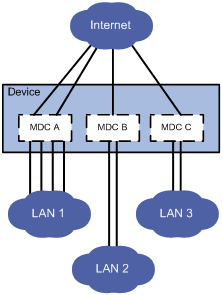
As shown in Figure 2, use the device to satisfy the Internet access requirements of three companies: Company A (LAN 1), Company B (LAN 2), and Company C (LAN 3).
The device has three interface cards, which reside in slot 2 to slot 4. Each card provides 48 Ethernet interfaces.
Company A has four departments, each of which has large amounts of traffic and needs a dedicated link to connect to the Internet gateway to achieve higher transmission speed. Company B and Company C each need two links to connect to the Internet gateway, one of which for redundancy.
Company A has many users and requires more disk space than Company B and Company C. Company B and Company C do not need a large amount of disk space and the default disk space is enough to satisfy their disk space requirements.
Company C has less employees and less Internet traffic, and needs only a small amount of CPU resources.
Configuration procedure
1. Create and configure MDCA for Company A:
# Create MDCA.
<Device> system-view
[Device] mdc MDCA
It will take some time to create MDC...
This MDC was created successfully.
# Authorize MDCA to use the interface card in slot 2.
[Device-mdc-2-MDCA] location slot 2
# Assign interfaces GigabitEthernet 2/0/1 through GigabitEthernet 2/0/48 to MDCA.
[Device-mdc-2-MDCA] allocate interface GigabitEthernet 2/0/1 to GigabitEthernet 2/0/48
The configurations of the interfaces will be lost. Continue? [Y/N]:y
# Specify that MDCA use up to 40 percent of the total disk space.
[Device-mdc-2-MDCA] limit-resource disk slot 0 ratio 40
# Start MDCA.
[Device-mdc-2-MDCA] mdc start
It will take some time to start MDC...
This MDC was started successfully.
[Device-mdc-2-MDCA] quit
# Log in to MDCA from the default MDC.
[Device] switchto mdc MDCA
******************************************************************************
* Copyright (c) 2004-2012 Hangzhou H3C Tech. Co., Ltd. All rights reserved. *
* Without the owner's prior written consent, *
* no decompiling or reverse-engineering shall be allowed. *
******************************************************************************
<Device> system-view
# Change the device name to MDCA for easy identification of the MDC.
[Device] sysname MDCA
# Create VLAN-interface 1 and assign an IP address to it.
[MDCA] interface vlan-interface 1
[MDCA-Vlan-interface1] ip address 192.168.1.251 24
# Return to the default MDC.
[MDCA-Vlan-interface1] return
<MDCA> switchback
[Device]
2. Create and configure MDCB for Company B:
# Create MDCB.
[Device] mdc MDCB
It will take some time to create MDC...
This MDC was created successfully.
# Authorize MDCB to use the interface card in slot 3.
[Device-mdc-3-MDCB] location slot 3
# Assign interfaces GigabitEthernet 3/0/1 through GigabitEthernet 3/0/48 to MDCB.
[Device-mdc-3-MDCB] allocate interface GigabitEthernet 3/0/1 to GigabitEthernet 3/0/48
The configurations of the interfaces will be lost. Continue? [Y/N]:y
# Start MDCB.
[Device-mdc-3-MDCB] mdc start
It will take some time to start MDC...
This MDC was started successfully.
[Device-mdc-3-MDCB] quit
# Log in to MDCB from the default MDC.
[Device] switchto mdc MDCB
******************************************************************************
* Copyright (c) 2004-2012 Hangzhou H3C Tech. Co., Ltd. All rights reserved. *
* Without the owner's prior written consent, *
* no decompiling or reverse-engineering shall be allowed. *
******************************************************************************
<Device> system-view
# Change the device name to MDCB for easy identification of the MDC.
[Device] sysname MDCB
# Create VLAN-interface 1 and assign an IP address to it.
[MDCB] interface vlan-interface 1
[MDCB-Vlan-interface1] ip address 192.168.2.251 24
# Return to the default MDC.
[MDCB-Vlan-interface1] return
<MDCB> switchback
[Device]
3. Create and configure MDCC for Company C:
# Create MDCC.
[Device] mdc MDCC
It will take some time to create MDC...
This MDC was created successfully.
# Authorize MDCC to use the interface card in slot 4.
[Device-mdc-4-MDCC] location slot 4
# Assign interfaces GigabitEthernet 4/0/1 through GigabitEthernet4/0/48 to MDCC.
[Device-mdc-4-MDCC] allocate interface GigabitEthernet 4/0/1 to GigabitEthernet 4/0/48
The configurations of the interfaces will be lost. Continue? [Y/N]:y
# Set the CPU weight of MDCC to 5.
[Device-mdc-4-MDCC] limit-resource cpu weight 5
# Start MDCC.
[Device-mdc-4-MDCC] mdc start
It will take some time to start MDC...
This MDC was started successfully.
[Device-mdc-4-MDCC] quit
# Log in to MDCC from the default MDC.
[Device] switchto mdc MDCC
******************************************************************************
* Copyright (c) 2004-2012 Hangzhou H3C Tech. Co., Ltd. All rights reserved. *
* Without the owner's prior written consent, *
* no decompiling or reverse-engineering shall be allowed. *
******************************************************************************
<Device> system-view
# Change the device name to MDCC for easy identification of the MDC.
[Device] sysname MDCC
# Create VLAN-interface 1 and assign an IP address to it.
[MDCC] interface vlan-interface 1
[MDCC-Vlan-interface1] ip address 192.168.3.251 24
# Return to the default MDC.
[MDCC-Vlan-interface1] return
<MDCC> switchback
[Device]
Verifying the configuration
1. Check whether the MDCs exist and are operating properly.
<Device> display mdc
ID Name Status
----------------------------------
1 Admin active
2 MDCA active
3 MDCB active
4 MDCC active
The output shows that the MDCs have been created and are operating properly.
2. Log in to MDCA as an administrator of Company A and then view the current configuration of the MDC.
C:\> telnet 192.168.1.251
******************************************************************************
* Copyright (c) 2004-2012 Hangzhou H3C Tech. Co., Ltd. All rights reserved. *
* Without the owner's prior written consent, *
* no decompiling or reverse-engineering shall be allowed. *
******************************************************************************
<MDCA> display current-configuration
…
MDC configuration example (in IRF mode)
Network requirements
As shown in Figure 3, a service provider wants to use one IRF fabric to satisfy the Internet access requirements of three companies: Company A (LAN 1), Company B (LAN 2), and Company C (LAN 3). The IRF fabric has two members. The master uses the ID 1 and has two interface cards, one in slot 2 and the other in slot 3. The subordinate member uses the ID 2 and has one interface card in slot 4. Each interface card provides 48 Ethernet interfaces.
Company A has four departments, and each department has large amounts of traffic and needs a dedicated link to connect to the Internet gateway to achieve higher transmission speed. Company B and Company C each need two links to connect to the Internet gateway, one of which for redundancy.
Company A has many users and requires more disk space than Company B and Company C. Company B and Company C do not need a large amount of disk space and the default disk space is enough to satisfy their disk space requirements.
Company C has less employees and less Internet traffic, and needs only a small amount of CPU resources.

Configuration procedure
1. Create and configure MDCA for Company A:
# Create MDCA.
<Device> system-view
[Device] mdc MDCA
It will take some time to create MDC...
This MDC was created successfully.
# Authorize MDCA to use the interface card in the master's slot 2.
[Device-mdc-2-MDCA] location chassis 1 slot 2
# Assign interfaces GigabitEthernet 1/2/0/1 through GigabitEthernet 1/2/0/48 to MDCA.
[Device-mdc-2-MDCA] allocate interface GigabitEthernet 1/2/0/1 to GigabitEthernet 1/2/0/48
The configurations of the interfaces will be lost. Continue? [Y/N]:y
# Specify that MDCA use up to 40 percent of the total disk space.
[Device-mdc-2-MDCA] limit-resource disk chassis 1 slot 0 ratio 40
# Start MDCA.
[Device-mdc-2-MDCA] mdc start
It will take some time to start MDC...
This MDC was started successfully.
[Device-mdc-2-MDCA] quit
******************************************************************************
* Copyright (c) 2004-2012 Hangzhou H3C Tech. Co., Ltd. All rights reserved. *
* Without the owner's prior written consent, *
* no decompiling or reverse-engineering shall be allowed. *
******************************************************************************
<Device> system-view
# Change the device name to MDCA for easy identification of the MDC.
[Device] sysname MDCA
# Create VLAN-interface 1 and assign an IP address to it.
[MDCA] interface vlan-interface 1
[MDCA-Vlan-interface1] ip address 192.168.1.251 24
# Return to the default MDC.
[MDCA-Vlan-interface1] return
<MDCA> switchback
[Device]
2. Create and configure MDCB for Company B:
# Create MDCB.
[Device] mdc MDCB
It will take some time to create MDC...
This MDC was created successfully.
# Authorize MDCB to use the interface card in the master's slot 3.
[Device-mdc-3-MDCB] location chassis 1 slot 3
# Assign interfaces GigabitEthernet 1/3/0/1 through GigabitEthernet 1/3/0/48 to MDCB.
[Device-mdc-3-MDCB] allocate interface GigabitEthernet 1/3/0/1 to GigabitEthernet 1/3/0/48
The configurations of the interfaces will be lost. Continue? [Y/N]:y
# Start MDCB.
[Device-mdc-3-MDCB] mdc start
It will take some time to start MDC...
This MDC was started successfully.
[Device-mdc-3-MDCB] quit
# Log in to MDCB from the default MDC.
[Device] switchto mdc MDCB
******************************************************************************
* Copyright (c) 2004-2012 Hangzhou H3C Tech. Co., Ltd. All rights reserved. *
* Without the owner's prior written consent, *
* no decompiling or reverse-engineering shall be allowed. *
******************************************************************************
<Device> system-view
# Change the device name to MDCB for easy identification of the MDC.
[Device] sysname MDCB
# Create VLAN-interface 1 and assign an IP address to it.
[MDCB] interface vlan-interface 1
[MDCB-Vlan-interface1] ip address 192.168.2.251 24
# Return to the default MDC.
[MDCB-Vlan-interface1] return
<MDCB> switchback
[Device]
3. Create and configure MDCC for Company C:
# Create MDCC.
[Device] mdc MDCC
It will take some time to create MDC...
This MDC was created successfully.
# Authorize MDCC to use the interface card in the subordinate member's slot 4.
[Device-mdc-4-MDCC] location chassis 2 slot 4
# Assign interfaces GigabitEthernet 2/4/0/1 through GigabitEthernet 2/4/0/48 to MDCC.
[Device-mdc-4-MDCC] allocate interface GigabitEthernet 2/4/0/1 to GigabitEthernet 2/4/0/48
The configurations of the interfaces will be lost. Continue? [Y/N]:y
# Set the CPU weight of MDCC to 5.
[Device-mdc-4-MDCC] limit-resource cpu weight 5
# Start MDCC.
[Device-mdc-4-MDCC] mdc start
It will take some time to start MDC...
This MDC was started successfully.
[Device-mdc-4-MDCC] quit
# Log in to MDCC from the default MDC.
[Device] switchto mdc MDCC
******************************************************************************
* Copyright (c) 2004-2012 Hangzhou H3C Tech. Co., Ltd. All rights reserved. *
* Without the owner's prior written consent, *
* no decompiling or reverse-engineering shall be allowed. *
******************************************************************************
<Device> system-view
# Change the device name to MDCC for easy identification of the MDC.
[Device] sysname MDCC
# Create VLAN-interface 1 and assign an IP address to it.
[MDCC] interface vlan-interface 1
[MDCC-Vlan-interface1] ip address 192.168.3.251 24
# Return to the default MDC.
[MDCC-Vlan-interface1] return
<MDCC> switchback
[Device]
Verifying the configuration
1. Check whether the MDCs exist and are operating properly.
<Device> display mdc
ID Name Status
----------------------------------
1 Admin active
2 MDCA active
3 MDCB active
4 MDCC active
The output shows that the MDCs have been created and are operating properly.
2. Log in to MDCA as an administrator of Company A and then view the current configuration of the MDC.
C:\> telnet 192.168.1.251
******************************************************************************
* Copyright (c) 2004-2012 Hangzhou H3C Tech. Co., Ltd. All rights reserved. *
* Without the owner's prior written consent, *
* no decompiling or reverse-engineering shall be allowed. *
******************************************************************************
<MDCA> display current-configuration
…