- Table of Contents
-
- 01-Fundamentals Configuration Guide
- 00-Preface
- 01-CLI configuration
- 02-RBAC configuration
- 03-Login management configuration
- 04-FTP and TFTP configuration
- 05-File system management configuration
- 06-Configuration file management configuration
- 07-Software upgrade configuration
- 08-ISSU configuration
- 09-Emergency shell configuration
- 10-Automatic configuration
- 11-Device management configuration
- 12-MDC configuration
- 13-TCL configuration
- 14-License management
- Related Documents
-
| Title | Size | Download |
|---|---|---|
| 11-Device management configuration | 223.95 KB |
Enabling displaying the copyright statement
Changing the brand name of an MPU
Schedule configuration example
Performing power supply management
Enabling power supply management
Re-assigning IDs to AC power supplies
Setting the port status detection timer
Setting memory usage thresholds
Configuring the temperature alarm thresholds
Configuring hardware failure detection and protection
Specifying the actions to be taken for hardware failures
Enabling hardware failure protection for interfaces
Enabling hardware failure protection for aggregation groups
Enabling data forwarding path failure detection
Verifying and diagnosing transceiver modules
Diagnosing transceiver modules
Disabling alarm traps for transceiver modules
Displaying and maintaining device management configuration
This chapter describes how to monitor the operating status of the device, configure the running parameters (such as the device name, system time, and the temperature alarm thresholds), and reboot the device.
You can perform the configuration tasks in this chapter in any order.
Configuring the device name
A device name, or "hostname" identifies a device in a network and is used as the user view prompt at the CLI. For example, if the device name is Sysname, the user view prompt is <Sysname>.
|
Step |
Command |
Remarks |
|
1. Enter system view. |
system-view |
N/A |
|
2. Configure the device name. |
sysname sysname |
The default device name is H3C |
Setting the system time
|
|
CAUTION: The system time is always restored to the default after a reboot. After rebooting the device, reconfigure the system time or configure NTP for the device. For more information about NTP, see Network Management and Monitoring Configuration Guide. |
The system time is determined by the UTC time, local time zone, and daylight saving time. You can use the display clock command to view the system time.
A correct system time setting is essential to network management and communication. Set the system time correctly or use NTP to synchronize your device with a trusted time source before you run it on the network.
|
Step |
Command |
Remarks |
|
1. Set the UTC time. |
clock datetime time date |
N/A |
|
1. Enter system view. |
system-view |
N/A |
|
2. Set the local time zone. |
clock timezone zone-name { add | minus } zone-offset |
The default local time zone is the UTC time zone. |
|
3. Set the daylight saving time |
clock summer-time name start-time start-date end-time end-date add-time |
By default, daylight saving time is disabled. |
Enabling displaying the copyright statement
By default, the device displays the copyright statement when a Telnet or SSH user logs in, or when a user quits user view through the console port, AUX port, or through Modem. You can disable or enable the function as needed. The following is a sample copyright statement:
****************************************************************************
* Copyright (c) 2004-2012 Hangzhou H3C Tech. Co., Ltd. All rights reserved.*
* Without the owner's prior written consent, *
* no decompiling or reverse-engineering shall be allowed. *
****************************************************************************
To enable displaying the copyright statement:
|
Step |
Command |
Remarks |
|
1. Enter system view. |
system-view |
N/A |
|
2. Enable displaying the copyright statement. |
copyright-info enable |
By default, this function is enabled. |
Configuring banners
Banners are messages that the system displays when a user logs in.
Banner types
The system supports the following banners:
· Legal banner—Appears after the copyright or license statement. To continue login, the user must enter Y or press Enter. To quit the process, the user must enter N. Y and N are case-insensitive.
· Message of the Day (MOTD) banner—Appears after the legal banner and before the login banner.
· Login banner—Appears only when password or scheme authentication has been configured.
· Incoming banner—Appears for Modem users.
· Shell banner—Appears for non-Modem users.
Banner input modes
You can configure a banner using one of the following approaches:
· Single-line input.
Input the entire banner in the same line as the command. The start and end delimiters for the banner can be any printable character but must be the same and not included in the banner. The input text, including the command keywords and the delimiters cannot exceed 510 characters. In this mode, do not press Enter before you input the end delimiter. For example, you can configure the shell banner "Have a nice day." as follows:
<System> system-view
[System] header shell %Have a nice day.%
· Multiple-line input.
Input message text in multiple lines. In this approach, the message text can be up to 2000 characters. Use one of the following methods to implement multi-line input mode:
¡ Method 1—Press Enter after the last command keyword. At the system prompt, enter the banner and end the last line with the delimiter character %. For example, you can configure the banner "Have a nice day. Please input the password." as follows:
<System> system-view
[System] header shell
Please input banner content, and quit with the character '%'.
Have a nice day.
Please input the password.%
¡ Method 2—After you type the last command keyword, type any single printable character as the start delimiter for the banner and press Enter. At the system prompt, type the banner and end the last line with the same delimiter. For example, you can configure the banner "Have a nice day. Please input the password." as follows:
<System> system-view
[System] header shell A
Please input banner content, and quit with the character 'A'.
Have a nice day.
Please input the password.A
¡ Method 3—After you type the last command keyword, type the start delimiter and part of the banner and press Enter. At the system prompt, enter the rest of the banner and end the last line with the same delimiter. For example, you can configure the banner "Have a nice day. Please input the password." as follows:
<System> system-view
[System] header shell AHave a nice day.
Please input banner content, and quit with the character 'A'.
Please input the password.
A
Configuration procedure
To configure banners:
|
Step |
Command |
Remarks |
|
1. Enter system view. |
system-view |
N/A |
|
2. Configure the legal banner. |
header legal text |
By default, no legal banner is configured. |
|
3. Configure the MOTD banner. |
header motd text |
By default, no MOTD banner is configured. |
|
4. Configure the login banner. |
header login text |
By default, no login banner is configured. |
|
5. Configure the incoming banner. |
header incoming text |
By default, no incoming banner is configured. |
|
6. Configure the shell banner. |
header shell text |
By default, no shell banner is configured. |
Changing the brand name of an MPU
The device supports both H3C MPUs and HP MPUs. Some network management software identifies a device by the brand name of the device's active MPU. If a device has two MPUs and the two MPUs have different brand names, the network management software considers the device a different one after an active/standby switchover occurs on the device. To avoid this problem, use the display brand command to view the brand names of the MPUs and change brand names to HP.
To change the brand name of an MPU:
|
Task |
Command |
Remarks |
|
Change the brand name of an MPU. |
· In standalone mode: · In IRF mode: |
The default brand name is H3C. Change to the brand name of an MPU takes effect after the MPU reboots. |
Setting the operating mode
The supported features and their specifications of the supported features vary with the device's operating mode.
The device can operate in the following modes:
· advance—Advanced mode.
· bridgee—Enhanced Layer 2 mode.
· routee—Enhanced Layer 3 mode.
· standard—Standard mode.
Change to the operating mode takes effect after a reboot.
To set the operating mode of the device:
|
Step |
Command |
Remarks |
|
1. Enter system view. |
system-view |
N/A |
|
2. Set the operating mode. |
system-working-mode { advance | bridgee | routee | standard } |
By default, the device operates in standard mode. |
Different operating modes support different types of cards, as shown in Table 1.
Table 1 Card types supported by operating modes
|
Operating mode |
EB card |
EC card |
EF card |
|
standard |
√ |
√ |
√ |
|
bridgee |
× |
√ |
√ |
|
routee |
× |
√ |
√ |
|
advance |
× |
× |
√ |
The √ sign stands for "supported." The × sign stands for "unsupported."
EB cards have the "EB" suffix in their silkscreens, such as LST1GP48LEB1. The similar is true for EC and EF cards.
Rebooting the device
|
|
CAUTION: · A reboot can interrupt network services. · To avoid configuration loss, use the save command to save the running configuration before a reboot. For more information about the save command, see Fundamentals Command Reference. · Before a reboot, use the display startup and display boot-loader commands to verify that you have correctly specified the startup configuration file and startup software images. If the main startup software images are corrupted or missing, you must respecify a set of main startup software images before using the reboot command to reboot the device. Otherwise, the device cannot start up. For more information about the two display commands, see Fundamentals Command Reference. |
You can reboot the device using one of the following methods:
· Power off and then power on the device. This method might cause data loss, and is the least-preferred method.
· Immediately reboot the device at the CLI.
· Schedule a reboot at the CLI, so the device automatically reboots at the specified time or after the specified period of time.
Reboot at the CLI enables easy remote device maintenance.
Configuration guidelines
If you execute the scheduler reboot at or scheduler reboot delay command multiple times, the most recent configuration takes effect.
In standalone mode, if an active/standby switchover occurs, the automatic reboot configuration is canceled.
In IRF mode, the automatic reboot configuration is effective for all member devices, and will be canceled if a switchover between the global active MPU and a global standby MPU occurs.
For data security, the device does not reboot while it is performing file operations.
Configuration procedure
|
Task |
Command |
|
Reboot a card or the entire device in standalone mode. |
reboot [ slot slot-number ] |
|
Reboot an IRF member device or all IRF member devices in IRF mode. |
reboot [ chassis chassis-number [ slot slot-number ] ] |
To schedule a reboot, execute either of the following commands in user view:
|
Task |
Command |
Remarks |
|
Specify the reboot date and time. |
scheduler reboot at time [ date ] |
By default, no reboot date or time is specified. |
|
Specify the reboot delay time. |
scheduler reboot delay time |
By default, no reboot delay time is specified. |
Scheduling a task
You can schedule the device to automatically execute a command or a set of commands to complete certain management tasks.
You can configure a one-time schedule or a periodic schedule. A one-time schedule is not saved to the configuration file, and is lost when the device reboots. A periodic schedule is saved to the startup configuration file and will be automatically executed periodically.
Configuration guidelines
· The default system time is always restored at reboot. To make sure a task schedule can be executed as expected, reconfigure the system time or configure NTP after you reboot the device. For more information about NTP, see Network Management and Monitoring Configuration Guide.
· Make sure all commands in a schedule are compliant to the command syntax. The system does not check the syntax when you assign a command to a job.
· A schedule cannot contain any of these commands: telnet, ftp, ssh2, and monitor process.
· A schedule does not support user interaction. If a command requires a yes or no answer, the system always assumes that a Y or Yes is entered. If a command requires a character string input, the system assumes that the default character string (if any) is entered, or a null string is entered.
· A schedule is executed in the background, and no output (except for logs, traps, and debug information) is displayed for the schedule.
Configuration procedure
To configure a one-time schedule for the device:
|
Step |
Command |
Remarks |
|
1. Enter system view. |
system-view |
N/A |
|
2. Create a job. |
scheduler job job-name |
By default, no job exists. |
|
3. Assign a command to the job. |
command id command |
By default, no command is assigned to a job. You can assign multiple commands to a job. A command with a smaller ID will be executed first. |
|
4. Create a schedule. |
scheduler schedule schedule-name |
By default, no schedule exists. |
|
5. Assign a job to a schedule. |
job job-name |
By default, no job is assigned to a schedule. You can assign multiple jobs to a schedule. The jobs will be executed concurrently. |
|
6. Specify an execution time table for the one-time schedule. |
· Specify the
execution date and time: · Specify the
execution days and time: · Specify the
execution delay time: |
Configure one command as required. By default, no execution time is specified for a schedule. Executing commands clock datetime, clock summer-time, and clock timezone does not change the execution time table that is already configured for a schedule. |
To configure a periodic schedule for the device:
|
Step |
Command |
Remarks |
|
1. Enter system view. |
system-view |
N/A |
|
2. Create a job. |
scheduler job job-name |
By default, no job exists. |
|
3. Assign a command to the job. |
command id command |
By default, no command is assigned to a job. You can assign multiple commands to a job. A job with a smaller ID will be executed first. |
|
4. Create a schedule. |
scheduler schedule schedule-name |
By default, no schedule exists. |
|
5. Assign a job to a schedule. |
job job-name |
By default, no job is assigned to a schedule. You can assign multiple jobs to a schedule. The jobs will be executed concurrently. |
|
6. Specify an execution time table for the periodic schedule |
· Execute the schedule at an interval from the specified time on: · Execute the schedule at the specified time on every specified day in a month
or week: |
Configure either command. By default, no execution time is specified for a schedule. Executing commands clock datetime, clock summer-time, and clock timezone does not change the execution time table that is already configured for a schedule. |
Schedule configuration example
Network requirements
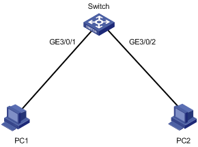
To save energy, configure the switch to enable interfaces GigabitEthernet 3/0/1 and GigabitEthernet 3/0/2 at 8:00 a.m. every Monday through Friday and disable the interfaces at 18:00 every Monday through Friday.
Figure 1 Network diagram
Scheduling procedure
# Enter system view.
<Sysname> system-view
# Configure a job for disabling interface GigabitEthernet 3/0/1.
[Sysname] scheduler job shutdown-GigabitEthernet3/0/1
[Sysname-job-shutdown-GigabitEthernet3/0/1] command 1 system-view
[Sysname-job-shutdown-GigabitEthernet3/0/1] command 2 interface GigabitEthernet 3/0/1
[Sysname-job-shutdown-GigabitEthernet3/0/1] command 3 shutdown
[Sysname-job-shutdown-GigabitEthernet3/0/1] quit
# Configure a job for enabling interface GigabitEthernet 3/0/1.
[Sysname] scheduler job start-GigabitEthernet3/0/1
[Sysname-job-start-GigabitEthernet3/0/1] command 1 system-view
[Sysname-job-start-GigabitEthernet3/0/1] command 2 interface GigabitEthernet 3/0/1
[Sysname-job-start-GigabitEthernet3/0/1] command 3 undo shutdown
[Sysname-job-start-GigabitEthernet3/0/1] quit
# Configure a job for disabling interface GigabitEthernet 3/0/2.
[Sysname] scheduler job shutdown-GigabitEthernet3/0/2
[Sysname-job-shutdown-GigabitEthernet3/0/2] command 1 system-view
[Sysname-job-shutdown-GigabitEthernet3/0/2] command 2 interface GigabitEthernet 3/0/2
[Sysname-job-shutdown-GigabitEthernet3/0/2] command 3 shutdown
[Sysname-job-shutdown-GigabitEthernet3/0/2] quit
# Configure a job for enabling interface GigabitEthernet 3/0/2.
[Sysname] scheduler job start-GigabitEthernet3/0/2
[Sysname-job-start-GigabitEthernet3/0/2] command 1 system-view
[Sysname-job-start-GigabitEthernet3/0/2] command 2 interface GigabitEthernet 3/0/2
[Sysname-job-start-GigabitEthernet3/0/2] command 3 undo shutdown
[Sysname-job-start-GigabitEthernet3/0/2] quit
# Configure a periodic schedule for enabling the interfaces at 8:00 a.m. every Monday through Friday.
[Sysname] scheduler schedule START-pc1/pc2
[Sysname-schedule-START-pc1/pc2] job start-GigabitEthernet3/0/1
[Sysname-schedule-START-pc1/pc2] job start-GigabitEthernet3/0/2
[Sysname-schedule-START-pc1/pc2] time repeating at 8:00 week-day mon tue wed thu fri
[Sysname-schedule-START-pc1/pc2] quit
# Configure a periodic schedule for disabling the interfaces at 18:00 every Monday through Friday.
[Sysname] scheduler schedule STOP-pc1/pc2
[Sysname-schedule-STOP-pc1/pc2] job shutdown-GigabitEthernet3/0/1
[Sysname-schedule-STOP-pc1/pc2] job shutdown-GigabitEthernet3/0/2
[Sysname-schedule-STOP-pc1/pc2] time repeating at 18:00 week-day mon tue wed thu fri
[Sysname-schedule-STOP-pc1/pc2] quit
Verifying the scheduling
# Display the configuration information of all jobs.
[Sysname] display scheduler job
Job name: shutdown-GigabitEthernet3/0/1
system-view
interface GigabitEthernet 3/0/1
shutdown
Job name: shutdown-GigabitEthernet3/0/2
system-view
interface GigabitEthernet 3/0/2
shutdown
Job name: start-GigabitEthernet3/0/1
system-view
interface GigabitEthernet 3/0/1
undo shutdown
Job name: start-GigabitEthernet3/0/2
system-view
interface GigabitEthernet 3/0/2
undo shutdown
# Display the schedule information.
[Sysname] display scheduler schedule
Schedule name : START-pc1/pc2
Schedule type : Run on every Mon Tue Wed Thu Fri at 08:00:00
Start time : Wed Sep 28 08:00:00 2011
Last execution time : Wed Sep 28 08:00:00 2011
Last completion time : Wed Sep 28 08:00:03 2011
Execution counts : 1
-----------------------------------------------------------------------
Job name Last execution status
start-GigabitEthernet3/0/1 Successful
start-GigabitEthernet3/0/2 Successful
Schedule name : STOP-pc1/pc2
Schedule type : Run on every Mon Tue Wed Thu Fri at 18:00:00
Start time : Wed Sep 28 18:00:00 2011
Last execution time : Wed Sep 28 18:00:00 2011
Last completion time : Wed Sep 28 18:00:01 2011
Execution counts : 1
-----------------------------------------------------------------------
Job name Last execution status
shutdown-GigabitEthernet3/0/1 Successful
shutdown-GigabitEthernet3/0/2 Successful
# Display schedule log information.
[Sysname] display scheduler logfile
Job name : start-GigabitEthernet3/0/1
Schedule name : START-pc1/pc2
Execution time : Wed Sep 28 08:00:00 2011
Completion time : Wed Sep 28 08:00:02 2011
--------------------------------- Job output -----------------------------------
<Sysname>system-view
System View: return to User View with Ctrl+Z.
[Sysname]interface GigabitEthernet 3/0/1
[Sysname-GigabitEthernet3/0/1]undo shutdown
Job name : start-GigabitEthernet3/0/2
Schedule name : START-pc1/pc2
Execution time : Wed Sep 28 08:00:00 2011
Completion time : Wed Sep 28 08:00:02 2011
--------------------------------- Job output -----------------------------------
<Sysname>system-view
System View: return to User View with Ctrl+Z.
[Sysname]interface GigabitEthernet 3/0/2.
[Sysname-GigabitEthernet3/0/2]undo shutdown
Job name : shutdown-GigabitEthernet3/0/1
Schedule name : STOP-pc1/pc2
Execution time : Wed Sep 28 18:00:00 2011
Completion time : Wed Sep 28 18:00:01 2011
--------------------------------- Job output -----------------------------------
<Sysname>system-view
System View: return to User View with Ctrl+Z.
[Sysname]interface GigabitEthernet 3/0/1
[Sysname-GigabitEthernet3/0/1]shutdown
Job name : shutdown-GigabitEthernet3/0/2
Schedule name : STOP-pc1/pc2
Execution time : Wed Sep 28 18:00:00 2011
Completion time : Wed Sep 28 18:00:01 2011
--------------------------------- Job output -----------------------------------
<Sysname>system-view
System View: return to User View with Ctrl+Z.
[Sysname]interface GigabitEthernet 3/0/2
[Sysname-GigabitEthernet3/0/2]shutdown
Performing power supply management
Enabling power supply management
Some power supplies have self protection mechanisms. When such a power supply encounters an overloading, over current, over voltage, over temperature, or short circuit problem, it implements a hardware protection measure to protect the whole device from being damaged, for example, powering off the device. Powering off the device helps protect the device, but doing so also interrupts the services. The power supply management function can minimize service interruption while protecting the device.
The power supply management function constantly monitors the available power and the system loads and takes protective measures in response to a potential power supply problem immediately so the power supplies do not need to perform hardware protection. Examples of protective measures include sending a notification, starting redundant power supplies, and powering off certain interface cards.
The power supply management function allows the device to have redundant power supplies for power supply backup. For example, for a device with three power supplies, you can specify one power supply as a redundant power supply, so the device can automatically start the redundant power supply and send trap information for alerts when a power supply in use fails or is removed, or when power consumption increases. You can view the power supply information of the device with the display power-supply command.
The power supply management function operates in the following scenarios:
· When an interface card is inserted to the device:
¡ If power supply management is disabled, the system immediately supplies power to the card. If the power is insufficient, the system powers off the entire device.
¡ If power supply management is enabled, the system compares the maximum power consumption of the inserted interface card with the available power. If the available power is sufficient for the card, the system supplies power to the interface card. Otherwise, the system starts the redundant power supplies. If the total power is still insufficient, the system does not supply power to the interface card.
· When the power is insufficient because a power supply fails or is removed:
¡ If power supply management is disabled, the power supplies perform self hardware protection.
¡ If power supply management is enabled, the system starts redundant power supplies as configured. If no redundant power supply is available, the system starts self hardware protection.
To enable power supply management in standalone mode:
|
Step |
Command |
Remarks |
|
1. Enter system view. |
system-view |
N/A |
|
2. Enable power supply management. |
power-supply policy enable |
By default, power supply management is enabled. |
|
3. Specify the number of redundant power supplies. |
power-supply policy redundant module-count |
The configuration of this command takes effect only when power supply management is enabled. |
To enable power supply management in IRF mode:
|
Step |
Command |
Remarks |
|
1. Enter system view. |
system-view |
N/A |
|
2. Enable power supply management. |
power-supply policy enable chassis chassis-number |
By default, power supply management is enabled. |
|
3. Specify the number of redundant power supplies. |
power-supply policy chassis chassis-number redundant module-count |
The configuration of this command takes effect only when power supply management is enabled. |
Powering on/off a card
You can manually power on or off cards to adjust the available power. The power supply status can be displayed with the display power-supply command.
To power on or off a card in standalone mode, execute one of the following commands in user view as appropriate:
|
Task |
Command |
Remarks |
|
Power on a card. |
power-supply on slot slot-number |
You cannot power on an MPU or switching fabric card. |
|
Power off a card. |
power-supply off slot slot-number |
You cannot power off an MPU or switching fabric card. |
To power on or off a card in IRF mode, execute one of the following commands in user view as appropriate:
|
Task |
Command |
Remarks |
|
Power on a card. |
power-supply on chassis chassis-number slot slot-number |
You cannot power on an MPU or switching fabric card. |
|
Power off a card. |
power-supply off chassis chassis-number slot slot-number |
You cannot power off an MPU or switching fabric card. To avoid IRF split, the system does not power off an interface card that contains all active physical IRF ports of a member device. |
Re-assigning IDs to AC power supplies
This feature applies only to PSE9000 AC power supplies.
Power supplies need IDs for easy identification. For PSE9000-A and PSE9000-D AC power supplies, the system automatically uses the numbers of the slots that hold the power supplies as the power supplies' IDs, as shown in Figure 2 and Figure 3. For PSE9000 AC power supplies, however, the system randomly assigns IDs at startup. These randomly assigned IDs have no relationship with the power supplies' slot numbers. You can re-assign IDs to PSE9000 AC power supplies after you install the device. For easy identification, H3C recommends you use the slot numbers as the power supplies' IDs.
Figure 2 Slot numbers of AC power supplies in an S12508
![]()
Figure 3 Slot numbers of AC power supplies in an S12518
To help you correlate the current IDs of AC power supplies with their slot numbers, the switch provides the power-supply led-blink command. After you execute this command for a power supply, the operation LED of the power supply blinks to show you its location. If you execute this command without specifying a power supply ID, all power supplies blink one by one in ascending order of IDs.
Configuration guidelines
Each AC power supply must have a unique ID.
To view the models and IDs of power supplies, use the display power-supply command.
If the switch reboots after AC power supplies get IDs:
· If no power supply changes occur or only some power supplies are removed since the last ID change, the IDs of the power supplies remain the same after the reboot.
· If some power supplies have been re-located or some power supplies have been added since the last ID change, the switch randomly re-assigns IDs to the power supplies after the reboot.
|
|
IMPORTANT: To hot-swap AC power supplies, follow these guidelines: · After you insert one AC power supply in to the power supply shelf, wait at least three seconds before inserting another one. · After you remove one AC power supply from the power supply shelf, wait at least 15 seconds before removing another one. Failing to follow these guidelines might cause multiple power supplies to use the same ID. |
Configuration procedure
To re-assign IDs to AC power supplies:
|
Step |
Command |
Remarks |
|
1. Enter system view. |
system-view |
N/A |
|
2. (Optional.) Correlate IDs randomly assigned by the system with the slot numbers of power supplies. |
·
In standalone mode: · In IRF mode: |
By default, the operation LED blink duration of an AC power supply is 3 seconds and the delay time is 0 seconds. |
|
3. Re-assign IDs to AC power supplies. |
·
In standalone mode: · In IRF mode: |
By default, the power supplies use the IDs randomly assigned by the system. |
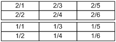
Configuration example
Figure 4 Intended IDs for the power supplies
![]()
To re-assign IDs to the three PSE9000 AC power supplies of a switch as shown in Figure 4:
1. Correlate the randomly assigned IDs with the slot numbers of power supplies.
<Sysname> system-view
[Sysname] power-supply led-blink module 1 blink-time 5 delay-time 10
[Sysname] power-supply led-blink module 2 blink-time 5 delay-time 10
[Sysname] power-supply led-blink module 3 blink-time 5 delay-time 10
Observe the operation LEDs of the power supplies after executing each power-supply led-blink command. Suppose the result is as shown in Figure 5.
Figure 5 Randomly assigned IDs of the power supplies
![]()
2. Re-assign IDs as required.
<Sysname> system-view
[Sysname] power-supply module 3 1 2 new-id 1 3 5
Setting the port status detection timer
To set the port status detection timer:
|
Step |
Command |
Remarks |
|
1. Enter system view. |
system-view |
N/A |
|
2. Set the port status detection timer. |
shutdown-interval time |
The default setting is 30 seconds. |
Setting memory usage thresholds
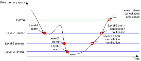
To ensure proper operation and improve memory utilization, the system monitors the amount of the free memory space in real time. When certain conditions are met, the system generates an alarm notification or an alarm cancellation notification and sends it to related service modules or processes so actions can be taken in response.
The system supports the following levels of thresholds:
· Normal level
· Level 1—Minor.
· Level 2—Severe.
· Level 3—Critical.
Figure 6 shows the triggering conditions for memory alarm notifications and memory alarm cancellation notifications:
|
Notification |
Triggering condition |
Remarks |
|
Level-1 alarm notification |
The amount of the free memory space goes down to or below the Level-1 alarm threshold for the first time. |
After generating and sending a Level-1 alarm notification, the system does not generate and send any additional Level-1 alarm notifications until the first Level-1 alarm is canceled. |
|
Level-2 alarm notification |
The amount of the free memory space goes down to or below the Level-2 alarm threshold for the first time. |
After generating and sending a Level-2 alarm notification, the system does not generate and send any additional Level-2 alarm notifications until the first Level-2 alarm is canceled. |
|
Level-3 alarm notification |
The amount of the free memory space goes down to or below the Level-3 alarm threshold for the first time. |
After generating and sending a Level-3 alarm notification, the system does not generate and send any additional Level-3 alarm notifications until the first Level-3 alarm is canceled. |
|
Level-3 alarm cancellation notification |
The amount of the free memory space goes up to or above the Level-2 alarm threshold. |
N/A |
|
Level-2 alarm cancellation notification |
The amount of the free memory space goes up to or above the Level-1 alarm threshold. |
N/A |
|
Level-1 alarm cancellation notification |
The amount of the free memory space goes up to or above the normal level threshold. |
N/A |
Figure 6 Memory alarm notification and alarm cancellation notification
To set memory usage thresholds:
|
Step |
Command |
Remarks |
|
1. Enter system view. |
system-view |
N/A |
|
2. Set memory usage thresholds. |
· In standalone mode: · In IRF mode: |
The defaults are as follows: · Level-1 threshold—96 MB. · Level-2 threshold—64 MB. · Level-3 threshold—48 MB. · Normal level threshold—128 MB. |
Configuring the temperature alarm thresholds
You can set a lower temperature threshold, warning temperature threshold, and alarming temperature threshold to monitor the temperature of the device through its temperature sensors.
When the temperature drops below the lower temperature threshold or reaches the warning temperature threshold, the device logs the event and sends out a log message and a trap.
When the temperature reaches the alarming temperature threshold, the device logs the event and notifies users by repeatedly sending log messages and traps and by setting the LEDs on the device panel.
To configure the temperature alarm thresholds:
Disabling all USB interfaces
This feature is supported only on the default MDC.
You can use USB interfaces to upload or download files. By default, all USB interfaces are enabled. You can disable USB interfaces as needed.
To disable all USB interfaces:
|
Step |
Command |
Remarks |
|
1. Enter system view. |
system-view |
N/A |
|
2. Disable all USB interfaces. |
usb disable |
By default, all USB interfaces are enabled. |
Isolating a card
When a card fails or an interface card's CPU daughter card logic needs to be upgraded, you can isolate the card from the system, so the card stops providing services without affecting the system operation and the services on other cards.
An isolated card is in offline state. You can use the display device command to verify the status.
Isolation guidelines
The active MPU cannot be isolated.
The last switching fabric card in a device cannot be isolated.
You cannot perform an ISSU when one or more cards are isolated.
Do not perform configurations for an isolated card. The configurations might not be able to take effect.
To eliminate possible impact on the system, H3C recommends you isolate a switching fabric card before removing it.
Isolation procedure
To isolate a card:
|
Step |
Command |
Remarks |
|
1. Enter system view. |
system-view |
N/A |
|
2. Isolate a card. |
· In standalone mode: · In IRF mode: |
By default, a card is not isolated. |
Configuring hardware failure detection and protection
Specifying the actions to be taken for hardware failures
The device automatically detects hardware failures on components, cards, and the forwarding plane. You can specify the actions to be taken in response to detected failures.
To specify the actions to be taken in response to hardware failures:
|
Step |
Command |
Remarks |
|
1. Enter system view. |
system-view |
N/A |
|
2. Specify the action to be taken in response to a type of hardware failures. |
hardware-failure-detection { board | chip | forwarding } { off | isolate | reset | warning } |
By default, the system takes the action of warning (sending traps) in response to hardware failures. |
Enabling hardware failure protection for interfaces
After you enable hardware failure protection on an interface, the system automatically shuts down the interface when it detects a hardware failure on the interface. An interface shut down this way is in Protect Down state.
Before enabling hardware failure protection on an interface, make sure a backup link is available for uninterrupted services.
After the failure on an interface is removed, bring the interface up using the undo shutdown command.
To enable hardware failure protection for an interface:
|
Step |
Command |
Remarks |
|
1. Enter system view. |
system-view |
N/A |
|
2. Set the action to be taken in response to failures on the forwarding plane to isolate. |
hardware-failure-detection forwarding isolate |
By default, the system takes the action of warning (sending traps) in response to forwarding-plane failures. |
|
3. Enter Ethernet interface view. |
interface interface-type interface-number |
N/A |
|
4. Enable hardware failure protection for the interface. |
hardware-failure-protection auto-down |
By default, hardware failure protection is enabled. |
Enabling hardware failure protection for aggregation groups
After you enable hardware failure protection for aggregation groups, the system follows the following rules when it detects a hardware failure on a member interface of an aggregation group:
· If the member interface is not the last member in up state in the group, the system shuts down the interface.
· If the member interface is the last member in up state in the group, the system does not shut down the interface.
To enable hardware failure protection for aggregation groups:
|
Step |
Command |
Remarks |
|
1. Enter system view. |
system-view |
N/A |
|
2. Set the action to be taken in response to failures on the forwarding plane to isolate. |
hardware-failure-detection forwarding isolate |
By default, the system takes the action of warning (sending traps) in response to forwarding-plane failures. |
|
3. Enter Ethernet interface view. |
interface interface-type interface-number |
N/A |
|
4. Disable hardware failure protection for the interface. |
undo hardware-failure-protection auto-down |
By default, hardware failure protection is enabled. Configure this command on every member interface in the aggregation group. If you do not configure this command on a member device, the system shuts down the interface when it detects a hardware failure on the interface, whether or not the interface is the last member in up state in the group. |
|
5. Exit to system view. |
quit |
N/A |
|
6. Enable hardware failure protection for aggregation groups. |
hardware-failure-protection aggregation |
By default, hardware failure protection is disabled for aggregation groups. |
The hardware-failure-protection aggregation and hardware-failure-protection auto-down commands do not take effect on an interface in the following cases:
· Loopback testing is enabled (using the loopback { external | internal } command).
· The interface is forcibly brought up (using the port up-mode command).
· The interface is a physical IRF port. For more information about physical IRF ports, see IRF Configuration Guide.
An interface shut down for hardware failure protection is in Protect DOWN state. You can use the display interface command to view the status. To restore the interface to UP state, execute the undo shutdown command.
For a card that is isolated or forbidden to load software for hardware failure protection, you can remove it and then reinstall it to restore it to operating state.
To view hardware failure detection and protection information, use the display hardware-failure-detection command.
Enabling data forwarding path failure detection
You can enable the device to automatically detect data forwarding path failures and output log information for notification.
To enable data forwarding path failure detection:
|
Step |
Command |
Remarks |
|
1. Enter system view. |
system-view |
N/A |
|
2. Enable data forwarding path failure detection. |
forward-path-detection enable |
By default, data forwarding path failure detection is enabled. |
Verifying and diagnosing transceiver modules
Verifying transceiver modules
You can use one of the following methods to verify the genuineness of a transceiver module:
· Display the key parameters of a transceiver module, including its transceiver type, connector type, central wavelength of the transmit laser, transfer distance, and vendor name.
· Display its electronic label. The electronic label is a profile of the transceiver module and contains the permanent configuration information, including the serial number, manufacturing date, and vendor name. The data is written to the storage component during debugging or testing.
To verify transceiver modules, execute the following commands in any view:
|
Task |
Command |
Remarks |
|
Display key parameters of transceiver modules. |
display transceiver { interface [ interface-type interface-number ] } |
N/A |
|
Display transceiver modules' electrical label information. |
display transceiver manuinfo interface [ interface-type interface-number ] } |
This command cannot display information for some transceiver modules. |
Diagnosing transceiver modules
The device provides the alarm and digital diagnosis functions for transceiver modules. When a transceiver module fails or is not operating correctly, you can check the alarms present on the transceiver module to identify the fault source or you can examine the key parameters monitored by the digital diagnosis function, including the temperature, voltage, laser bias current, TX power, and RX power.
To diagnose transceiver modules, execute the following command in any view:
|
Task |
Command |
Remarks |
|
Display alarms present on transceiver modules. |
display transceiver alarm { interface [ interface-type interface-number ] } |
N/A |
|
Display the current measured values of the digital diagnosis parameters for transceiver modules. |
display transceiver diagnosis { interface [ interface-type interface-number ] } |
This command cannot display information for some transceiver modules. |
Disabling alarm traps for transceiver modules
If you install a transceiver module that has no vendor name or a vendor name other than H3C, the system repeatedly outputs traps and logs to notify the user to replace the module. To continue to use such a transceiver module that is manufactured or customized by H3C but has no vendor information, you can disable alarm traps so the system stops outputting alarm traps.
To disable alarm traps for transceiver modules:
|
Step |
Command |
Remarks |
|
1. Enter system view. |
system-view |
N/A |
|
2. Disable alarm traps for transceiver modules. |
transceiver phony-alarm-disable |
By default, alarm traps are enabled for transceiver modules. |
Displaying and maintaining device management configuration
Execute display commands in any view and reset commands in user view.
In standalone mode:
|
Task |
Command |
|
Display device alarm information. |
display alarm [ slot slot-number ] |
|
Display MPUs' brand information. |
display brand |
|
Display the system time, date, local time zone, and daylight saving time. |
display clock |
|
Display the copyright statement. |
display copyright |
|
Display CPU usage statistics. |
display cpu-usage [ slot slot-number [ cpu cpu-number ] ] |
|
Display historical CPU usage statistics in a chart. |
display cpu-usage history [ job job-id ] [ slot slot-number [ cpu cpu-number ] ] |
|
Display hardware information. |
display device [ cf-card ] [ slot slot-number | verbose ] |
|
Display the electronic label data for the device. |
display device manuinfo [ slot slot-number ] |
|
Display the electronic label data for the specified chassis backplane. |
display device manuinfo chassis-only |
|
Display the electronic label data for the specified fan. |
display device manuinfo fan fan-id |
|
Display the electronic label data for the specified power supply. |
display device manuinfo power power-id |
|
Display the electronic label data of a power monitoring unit. |
display device manuinfo power-monitor pmu-id |
|
Display the operating statistics for multiple feature modules. |
display diagnostic-information [ hardware | infrastructure | l2 | l3 | service ] |
|
Display device temperature statistics. |
display environment [ slot slot-number ] |
|
Display the operating states of fans. |
display fan [ verbose ] |
|
Display hardware failure detection and fix information. |
display hardware-failure-detection |
|
Display hardware failure protection information. |
display hardware-failure-protection |
|
Display memory usage statistics. |
display memory [ slot slot-number [ cpu cpu-number ] ] |
|
Display memory usage thresholds. |
display memory-threshold [ slot slot-number ] |
|
Display power supply information. |
display power-supply [ verbose ] |
|
Display job configuration information. |
display scheduler job [ job-name ] |
|
Display job execution log information. |
display scheduler logfile |
|
Display the automatic reboot schedule. |
display scheduler reboot |
|
Display schedule information. |
display scheduler schedule [ schedule-name ] |
|
Display the current system operating mode. |
display system-working-mode |
|
Display system version information. |
display version |
|
Clear job execution log information. |
reset scheduler logfile |
In IRF mode:
|
Task |
Command |
|
Display device alarm information. |
display alarm [ chassis chassis-number slot slot-number ] |
|
Display MPUs' brand information. |
display brand |
|
Display the system time ,date, local time zone, and daylight saving time. |
display clock |
|
Display the copyright statement. |
display copyright |
|
Display CPU usage statistics. |
display cpu-usage [ chassis chassis-number slot slot-number [ cpu cpu-number ] ] |
|
Display historical CPU usage statistics in a chart. |
display cpu-usage history [ job job-id ] [ chassis chassis-number slot slot-number [ cpu cpu-number ] ] |
|
Display hardware information. |
display device [ cf-card ] [ chassis chassis-number [ slot slot-number ] | verbose ] |
|
Display the electronic label data for the device. |
display device manuinfo [ chassis chassis-number [ slot slot-number ] ] |
|
Display the electronic label data for the specified chassis backplane. |
display device manuinfo chassis chassis-number chassis-only |
|
Display the electronic label data for the specified fan. |
display device manuinfo chassis chassis-number fan fan-id |
|
Display the electronic label data for the specified power supply. |
display device manuinfo chassis chassis-number power power-id |
|
Display the electronic label data of a power monitoring unit. |
display device manuinfo chassis chassis-number power-monitor pmu-id |
|
Display the operating statistics for multiple feature modules. |
display diagnostic-information [ hardware | infrastructure | l2 | l3 | service ] |
|
Display device temperature statistics. |
display environment [ chassis chassis-number [ slot slot-number ] ] |
|
Display the operating states of fans. |
display fan [ chassis chassis-number ] [ verbose ] |
|
Display memory usage statistics. |
display memory [ chassis chassis-number slot slot-number [ cpu cpu-number ] ] |
|
Display memory usage thresholds. |
display memory-threshold [ chassis chassis-number slot slot-number ] |
|
Display power supply information. |
display power-supply [ chassis chassis-number ] [ verbose ] |
|
Display job configuration information. |
display scheduler job [ job-name ] |
|
Display job execution log information. |
display scheduler logfile |
|
Display the automatic reboot schedule. |
display scheduler reboot |
|
Display schedule information. |
display scheduler schedule [ schedule-name ] |
|
Display the current system operating mode. |
display system-working-mode |
|
Display system version information. |
display version |
|
Clear job execution log information. |
reset scheduler logfile |
For more information about the display memory command, see Network Management and Monitoring Command Reference.