- Table of Contents
- Related Documents
-
| Title | Size | Download |
|---|---|---|
| 07-WDS Configuration | 129.44 KB |
Table of Contents
Mapping a Mesh Profile to the Radio of an MP
Mapping an MP Policy to the Radio of an MP
Specifying a Peer MAC Address on the Radio
Displaying and Maintaining WDS
WDS Point to Point Configuration Example
WDS Point to Multi-Point Configuration Example
l The models listed in this document are not applicable to all regions. Please consult your local sales office for the models applicable to your region.
l Support of the H3C WA series WLAN access points (APs) for features may vary by AP model. For more information, see Feature Matrix.
l The interface types and the number of interfaces vary by AP model.
l The radio types supported by the H3C WA series WLAN access points vary by AP model.
l The term AP in this document refers to common APs, wireless bridges, or mesh APs.
This chapter includes these sections:
l Configuring WDS Port Security
l Mapping a Mesh Profile to the Radio of an MP
l Mapping an MP Policy to the Radio of an MP
l Specifying a Peer MAC Address on the Radio
l Displaying and Maintaining WDS
Introduction to WDS
WLAN distribution system (WDS) wireless bridging provides wireless links to connect two or more separate wired LANs or WLANs.
Advantages of WDS
At present, 802.11 based WLAN technologies are widely applied in the home, SOHO, and enterprise scenarios, allowing users to easily access the Internet. Currently, to provide network access services for wireless users, APs have to be connected to existing wired networks. As a result, the network deployment cost is high, and it requires a lot time to deploy a large-scaled network.
WDS makes you deploy a WLAN easily in some complex environments. It has following advantages:
l Providing wireless connectivity between two separate LAN segments.
l Low cost for high performance deployment options
l Expandable without the need for new wiring or more access points
l Easy to deploy in scenarios of metro, company, office, large warehouses, manufacturing, ports and waterfronts and so on
Deployment Scenarios
The WDS feature provides the following three topologies as required by actual applications.
Point to point bridge connection
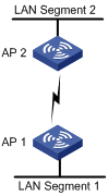
As shown in Figure 1-1, AP 1 and AP 2 create a WDS bridge link to connect LAN segment 1 and LAN segment 2 to form a unified LAN. When users in LAN segment 1 are to access resources of LAN segment 2, all packets will be transformed into wireless packets by AP 1, sent to AP 2 through the wireless bridge link, restored on AP 2, and then sent to the destination, and vice versa.
Figure 1-1 WDS point to point topology
Point to multi-point bridge connection
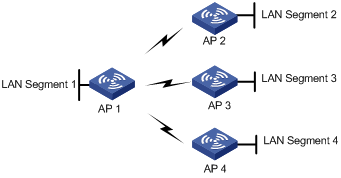
In this topology, a device acts as the centralized device, and all the other devices set up wireless bridge connections with only the centralized device, to interconnect multiple networks. This method conveniently connects multiple network islands to existing networks. However, all data exchanged between any two branch networks is forwarded by the centralized device.
Figure 1-2 WDS point to multi-point topology
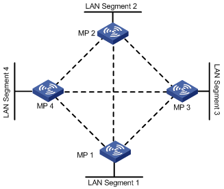
Mesh bridge connection
In this topology, multiple bridging devices form mesh wireless bridge connections and interconnect multiple LANs through manual configuration or self detection. In a mesh bridge network, when a WDS link fails, a backup link can take over. However, you need to use STP to eliminate loops in actual applications.
WDS Configuration Task List
Complete the following tasks to configure WDS:
|
Remarks |
|
|
Required |
|
|
Required |
|
|
Optional |
|
|
Optional |
|
|
Required |
|
|
Required |
Configuring WDS Port Security
Follow these steps to configure WDS port security:
|
To do… |
Use the command… |
Remarks |
|
Enter system view |
system-view |
— |
|
Enter WLAN mesh interface view |
interface wlan-mesh interface-number |
— |
|
Enable 11key negotiation |
port-security tx-key-type 11key |
Required By default, 11key negotiation is disabled. |
|
Configure a PSK |
port-security preshared-key { pass-phrase | raw-key } key |
Required By default, no PSK is configured. |
|
Configure the port to operate in PSK mode |
port-security port-mode psk |
Required By default, the port operates in noRestrictions mode. |
![]()
For more information about the port-security tx-key-type, port-security preshared-key, and port-security port-mode commands, see Port Security in the Security Command Reference.
Configuring a Mesh Profile
A mesh profile is created and mapped to an MP so that it can provide WDS services to other MPs that have the same mesh profile mapped.
Follow these steps to configure a mesh profile:
|
To do… |
Use the command… |
Remarks |
|
Enter system view |
system-view |
— |
|
Create a mesh profile and enter mesh profile view |
wlan mesh-profile mesh-profile-number |
— |
|
Configure the mesh ID |
mesh-id mesh-id-name |
Required By default, no mesh ID is set for the mesh profile. |
|
Bind a WLAN mesh interface |
bind wlan-mesh interface-index |
Required By default, no interface is bound to the mesh profile. |
|
Configure the WDS link keep alive interval |
link-keep-alive keep-alive-interval |
Optional By default, the WDS link keep-alive interval is 2 seconds. |
|
Enable the mesh profile |
mesh-profile enable |
Required By default, the mesh profile is disabled. |
|
Return to system view |
quit |
— |
Configuring an MP Policy
Link formation and maintenance are driven by the attributes specified in the MP policy.
Follow these steps to configure an MP policy:
|
To do… |
Use the command… |
Remarks |
|
Enter system view |
system-view |
— |
|
Create an MP policy and enter MP policy view |
wlan mp-policy policy-name |
Required By default, the default MP policy “default_mp_plcy” is adopted for the radio. |
|
Enable link initiation |
link-initiation enable |
Optional By default, link initiation is enabled. |
|
Configure the maximum number of links |
link-maximum-number max-link-number |
Optional By default, the maximum number is 2. |
|
Configure the link formation/link hold RSSI |
link-hold-rssi value |
Optional 15 dBm by default |
|
Configure the link saturation RSSI |
link-saturation-rssi value |
Optional 100 dBm by default |
|
Configure the probe request interval |
probe-request-interval interval-value |
Optional By default, the probe request interval is 1000 ms. |
|
Configure the link rate mode |
link rate-mode { fixed | real-time } |
Optional The default link rate mode is fixed. |
Mapping a Mesh Profile to the Radio of an MP
To enable a WDS service, a mesh profile must be mapped to the radio of the MP.
Follow these steps to map a mesh profile to a radio:
|
To do… |
Use the command… |
Remarks |
|
Enter system view |
system-view |
— |
|
Enter radio interface view |
interface wlan-radio interface-number |
— |
|
Map the mesh profile to the radio interface |
mesh-profile mesh-profile-number |
Required By default, no mesh profile is mapped to the radio. |
![]()
l The WLAN mesh interface of the MP will be created if the MP is in running state and the mapped mesh profile is enabled.
l You need to manually specify the working channels of the radios on the two APs for which a WDS link is to be established, and the working channels must be the same.
Mapping an MP Policy to the Radio of an MP
An MP policy should be mapped to a radio so that link formation and maintenance on the radio can be driven by the attributes specified in the MP policy.
Follow these steps to map an MP policy to the radio:
|
To do… |
Use the command… |
Remarks |
|
Enter system view |
system-view |
— |
|
Enter radio interface view |
interface wlan-radio interface-number |
— |
|
Map the MP policy to the radio |
mp-policy my-policy-name |
Required By default, the default MP policy “default_mp_plcy” is adopted for the radio. |
Specifying a Peer MAC Address on the Radio
You need to specify the MAC addresses of allowed peers on the local radio interface.
Follow these steps to specify a peer MAC address on a radio interface:
|
To do… |
Use the command… |
Remarks |
|
Enter system view |
system-view |
— |
|
Enter radio interface view |
interface wlan-radio interface-number |
— |
|
Specify the MAC address of a permitted peer |
mesh peer-mac-address mac-address |
Optional By default, the radio has no peer MAC address configured, and thus all neighbors are permitted. |
Displaying and Maintaining WDS
|
To do… |
Use the command… |
Remarks |
|
Display WDS link information |
display wlan mesh-link { mesh-profile mesh-profile-number | radio radio-number | peer-mac-address mac-address | all } |
Available in any view |
|
Display mesh profile information |
display wlan mesh-profile { mesh-profile-number | all } |
Available in any view |
|
Display MP policy information |
display wlan mp-policy { mp-policy-name | all } |
Available in any view |
WDS Configuration Examples
WDS Point to Point Configuration Example
Network requirements
In an outdoor environment as shown in Figure 1-4, connecting the two LAN segments with cables is time-consuming and cost ineffective. Therefore, you can connect the two LAN segments with a WDS link. More specifically:
l Connect AP 1 and AP 2 to different LAN segments.
l Configure AP 1 and AP 2 to use channel 153 to establish the 802.11a WDS link.
l Configure preshared key 12345678 to ensure WDS link security.
Figure 1-4 WDS point to point configuration
Configuration procedure
Because the WDS point to point configuration made on the two APs are similar, the following only gives the configuration on AP 1.
# Enable port security.
<AP1> system-view
[AP1] port-security enable
# Configure the port mode as psk, configure a PSK key of 12345678, and configure 11key negotiation.
[AP1] interface WLAN-MESH 1
[AP1-WLAN-MESH1] port-security port-mode psk
[AP1-WLAN-MESH1] port-security preshared-key pass-phrase simple 12345678
[AP1-WLAN-MESH1] port-security tx-key-type 11key
[AP1-WLAN-MESH1] quit
# Configure the mesh profile, specify the mesh ID of the current mesh profile as outdoor, bind WLAN-Mesh 1 to the service template, and enable the current mesh profile.
[AP1] wlan mesh-profile 1
[AP1-wlan-mshp-1] mesh-id outdoor
[AP1-wlan-mshp-1] bind WLAN-MESH 1
[AP1-wlan-mshp-1] mesh-profile enable
[AP1-wlan-mshp-1] quit
# Enter the radio interface view and specify the working channel as 153.
[AP1] interface WLAN-Radio 1/0/1
[AP1-WLAN-Radio1/0/1] radio-type dot11a
[AP1-WLAN-Radio1/0/1] channel 153
![]()
Configure the same working channel for AP 1 and AP 2, that is, if you select channel 153 as the WDS channel for AP 1, you need to also select the same channel for AP 2.
# Configure the peer MAC address on the radio interface, namely, the MAC address of the radio interface on AP 2.
[AP1-WLAN-Radio1/0/1] mesh peer-mac-address 0ebb-01bb-bb00
# Map the mesh profile to the radio interface.
[AP1-WLAN-Radio1/0/1] mesh-profile 1
The configuration of AP 2 is the same as that of AP 1. You only need to configure the peer MAC address as the MAC address of AP 1.
Configuration verification
After the devices on the two ends of the WDS link are configured, you can use the display command to view whether the WDS link has been established successfully.
# View the WDS link information on AP 1.
<AP1> display wlan mesh-link all
Peer Link Information
-------------------------------------------------------------------------------
Nbr-Mac BSSID Interface Link-state Uptime (hh:mm:ss)
0ebb-01bb-bb00 000f-e212-1200 WLAN-MESHLINK62 Active 0:17:59
-------------------------------------------------------------------------------
The output information shows that the WDS link between AP 1 and AP 2 has been established successfully.
WDS Point to Multi-Point Configuration Example
Network requirements
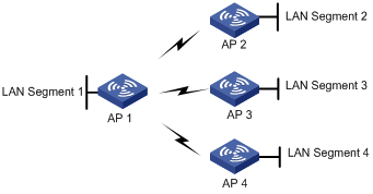
l As shown in the following figure, AP 1, AP 2, AP 3, and AP 4 are connected to different LAN segments.
l It is required that AP 1 establish a WDS link with AP 2, AP 3, and AP 4 respectively.
Figure 1-5 WDS point to multi-point configuration
Configuration procedure
WDS point-to-multi-point configuration is the WDS point-to-point configuration. Note the following when configuring WDS:
l Configure a neighbor MAC address for each radio interface (otherwise, WDS links may be set up between AP 2, AP 3, and AP 4).
l Set the maximum number of WDS links allowed. The default value is 2. It should be set to 3 for AP 1 in this example.
Configuration verification
l It is displayed that AP 1 has established a WDS link with AP 2, AP 3 and AP 4 respectively after execution of the display wlan mesh-link all command on AP 1.
l It is displayed that AP 2, AP 3 and AP 4 have respectively established a WDS link with AP 1 after execution of the display wlan mesh-link all command on them.