- Released At: 28-02-2025
- Page Views:
- Downloads:
- Table of Contents
- Related Documents
-
|
|
|
|
|
iNQA Technology White Paper |
|
|
Copyright © 2021 New H3C Technologies Co., Ltd. All rights reserved.
No part of this manual may be reproduced or transmitted in any form or by any means without prior written consent of New H3C Technologies Co., Ltd.
Except for the trademarks of New H3C Technologies Co., Ltd., any trademarks that may be mentioned in this document are the property of their respective owners.
This document provides generic technical information, some of which might not be applicable to your products.
The information in this document is subject to change without notice.
Contents
Packet coloring and counting mechanism
Point-to-point iNQA packet loss measurement
Point-to-multipoint iNQA packet loss measurement
Overview
Intelligent Network Quality Analyzer (iNQA) allows you to measure network performance quickly in large-scale IP networks. iNQA supports measuring packet loss on forward, backward, and bidirectional flows. The packet loss data includes number of lost packets, packet loss rate, number of lost bytes, and byte loss rate. The measurement results help you know when and where the packet loss occurs and the event severity level.
Technical background
At present, newly-emerged network services impose higher requirements on network performance. Among them, audio and video services are the most widely used, and they are sensitive to packet loss, delay, and jitter. A high packet loss rate and large delay causes voice stuttering and erratic display, affecting the user experience and even causing communication failures. When the quality of audio and video services declines, quick fault location and troubleshooting are desired.
The following measurement methods are supported to measure packet loss and delay:
· Indirect measurement—Uses simulated service packets to calculate packet loss and delay results.
· Direct measurement—Counts real service packets directly for packet loss and delay results.
Table 1 describes the common traditional measurement methods. These traditional measurement methods can locate the packet loss and packet delay quickly in small-scale IP networks rather than large-scale IP networks. However, in large-scale IP networks, using traditional measurement methods encounters slow fault location, high consumption, and difficult fault location.
Table 1 Traditional measurement methods
|
Measurement method |
Traditional measurement technologies |
Remarks |
|
Indirect measurement |
· Ping · NQA · TWAMP Light |
· Support only Layer 3 IP networks. · Take a long time to locate the network faults because it tries to establish connections with the possibly faulty devices one by one to gradually narrow the fault detection range. · Support only point-to-point measurement. · Use simulated service packets. |
|
Direct measurement |
Y.1731 (Connectivity Fault Detection) |
· Support only Layer 2 IP networks. · Take a long time to locate the network faults because it tries to establish connections with the possibly faulty devices one by one to gradually narrow the fault detection range. · Support point-to-point, point-to-multipoint, and multipoint-to-multipoint measurements. · Provide true measurement results by counting real service packets. |
|
RFC 6374/6375 (for MPLS networks) |
· Support only MPLS networks. · Take a long time to locate the network faults because it detects the packet loss on segments one by one to gradually narrow the packet loss range. · Support only point-to-point measurement. · Provide true measurement results by counting real service packets. |
Benefits
iNQA provides the following benefits:
· True measurement results—iNQA measures the service packets directly to calculate packet loss results, thus reflecting the real network quality.
· Wide application range—Applicable to Layer 2 and Layer 3 IP networks.
· Fast fault location—iNQA's periodic per-segment measurement allows for faster fault location than traditional measurement methods that continuously try to establish connections with the possibly faulty devices one by one after packet loss is reported on the network.
· Applicable to different applications—You can apply iNQA to multiple scenarios, such as point-to-point, point-to-multipoint, and multipoint-to-multipoint.
Implementation
Concepts
Figure 1 shows the important iNQA concepts including MP, collector, analyzer, and AMS.
Collector
The collector manages MPs, collects data from MPs, and reports the data to the analyzer.
Analyzer
The analyzer collects the data from collector instances and summarizes the data.
To improve the device utilization, a device supports both the collector and analyzer functionalities. You can enable the collector and analyzer functionalities on different devices or the same device.
Target flow
A target flow is a service flow defined by using any combination of the following items: source IPv4 address/segment, destination IPv4 address/segment, protocol type, source port number, destination port number, and DSCP value. Using more items defines a more explicit flow and generates more accurate analysis data.
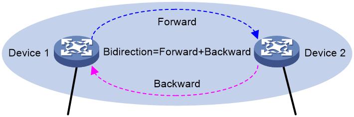
iNQA measures the flow data according to the flow direction. After you define a forward flow, the flow in the opposite direction is a backward flow. The bidirectional flows refer to a forward flow and a backward flow. As shown in Figure 2, if you define the flow from Device 1 to Device 2 as the forward flow, a flow from Device 2 to Device 1 is the backward flow. If you want to measure the packet loss on forward and backward flows between Device 1 and Device 2, you can specify bidirectional flows. The intermediate devices between the ingress and egress devices of the bidirectional flows can be the same or different.
MP
MP is a logical concept. An MP counts statistics and generates data for a flow. To measure packet loss on an interface on a collector, an MP must be bound to the interface.
An MP can be the following types:
· An ingress point refers to the point that the flow enters the network. It colors the forward flow, and decolors the backward flow, and collects packet statistics for the target flow.
· An egress point refers to the point that the flow leaves the network. It decolors the forward flow, colors the backward flow, and collects packet statistics for the target flow.
· A middle point refers to the point between an ingress point and egress point. It only collects packet statistics for the target flow. When packet loss occurs between an ingress point and egress point, you can specify middle points to locate the problem.
AMS
Configured on the analyzer, an AMS defines a measurement span for point-to-point measurement. You can configure multiple AMSs for an instance, and each AMS can be bound to MPs on any collector of the same instance. Therefore, iNQA can measure and summarize the data of the forward flow, backward flow, or bidirectional flows in any AMS.
Each AMS has an ingress MP group and egress MP group. The ingress MP group is the set of the ingress MPs in the AMS and the egress MP group is the set of the egress MPs.
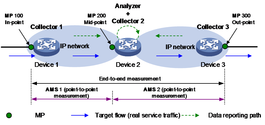
As shown in Figure 1:
· To measure the packet loss between MP 100 and MP 300, AMS is not needed.
· If packet loss occurs between MP 100 and MP 300, configure AMS 1 and AMS 2 on the analyzer to locate on which span the packet loss occurs.
¡ Bind MP 100 of collector 1 and MP 200 of collector 2 to AMS 1.
¡ Bind MP 200 of collector 2 and MP 300 of collector 3 to AMS 2.
Instance
The instance allows measurement on a per-flow basis. In an instance, you can configure the target flow, flow direction, MPs, and measurement interval.
On the collector and analyzer, create an instance of the same ID for the same target flow. An instance can be bound to only one target flow. On the same device, you can configure multiple instances to measure and collect the packet loss rate of different target flows.
Flag bit
Flag bits, also called color bits, are used to distinguish target flows from unintended traffic flows.
iNQA uses ToS field bits 5 to 7 in the IPv4 packet header as the flag bit.
The ToS field consist of a 6-bit (bits 0 to 5) DSCP filed and a 2-bit (bits 6 to 7) ECN field. If bit 5 is used as the flag bit, do not use it for DSCP purposes to avoid inaccurate packet loss statistics.
Mechanism
Time synchronization
iNQA uses the model of multi-point collection and single-point calculation. Multiple collectors collect and report the packet data periodically and one analyzer calculates the data periodically.
Before the iNQA measurement starts, all participating devices are time synchronized through NTP or PTP. All collectors must be time synchronized so that they use the same measurement interval for packet coloring, counting, and data reporting, ensuring accurate measurement results. Although the time inconsistency between the analyzer and a collector does not affect the measurement results, synchronize their clocks for easy management and maintenance. For more information about NTP and PTP, see the NTP and PTP configuration in the product documents.
Packet coloring and counting mechanism
Packet coloring and counting are important in iNQA. Packet coloring and the accuracy of the counting results directly affect the accuracy of iNQA measurement.
With iNQA measurement enabled, iNQA measures packet loss rate continuously. To facilitate the users to understand the packet loss situation at any time, iNQA measures the packet loss rate periodically. To ensure the periodical measurement and measurement accuracy, iNQA uses the coloring technology that sets the flag bit value to 1 or 0 alternately to distinguish packets between adjacent statistical periods. During the coloring period, iNQA counts only the colored packets. During the non-coloring period, iNQA counts only the uncolored packets.
The packet coloring and counting mechanism works as follows:
· After receiving the packets, the sender (an ingress point) performs the following tasks:
¡ Identifies the target flow.
¡ Alternately colors and decolors the packets and count the packets in each statistical period.
¡ Sends the counting results to the analyzer.
· After receiving the packets, the receiver (a middle point) performs the following tasks:
¡ Identifies the target flow.
¡ Collects packet statistics for the target flow.
¡ Sends the counting results to the analyzer.
¡ Forwards the packets to the next hop.
· After receiving the packets, the receiver (an egress point) performs the following tasks:
¡ Identifies the target flow.
¡ Collects packet statistics for the target flow.
¡ Sends the counting results to the analyzer.
¡ Decolors the packets and forward the packets to the next hop.
To ensure the accuracy of the packet counting results, the following rules apply:
· All MPs use two counters at the same time.
¡ The counter for colored packets is used to count the number of colored packets and the bytes of colored packets.
¡ The counter for uncolored packets is used to count the number of uncolored packets and the bytes of uncolored packets.
· Coloring period and non-coloring period start in turn.
· The packet receiving period is longer than the packet sending period.
Figure 3 Packet coloring and counting mechanism

As shown in Figure 3, the following shows the packet coloring and counting processes:
1. t0—The sender starts the first coloring period. During the period, the sender colors the packets and counts the colored packets. The receiver starts the counter for colored packets and counts them.
2. t1—The first colored packet from the sender arrives at the receiver, and the receiver counts the first colored packet.
3. t2—The sender ends the first coloring period and reports the number of colored packets and bytes to the analyzer. It also starts the first non-coloring period and counts the uncolored packets. The receiver starts the counter for uncolored packets and counts them.
4. t3—The receiver ends the counting of colored packets, and report the number of colored packets and bytes to the analyzer.
To minimize the impact of network delay and transmission disorder on the calculation results, the receiver ends a statistical period at a time later than t2. The statistical period for receiving colored packets starts from t0 and ends in t3. During the statistical period for colored packets, the counter for colored packets at the receiver counts only colored packets to ensure that the colored packets arriving with a delay can be counted.
5. t4—The sender ends a non-coloring period, reports the counted number of uncolored packets and the counted bytes of uncolored packets to the analyzer, and starts counting the colored packets. The receiver starts counting the colored packets.
6. t5—The receiver ends the counting of uncolored packets, and report the counted number of uncolored packets and the counted bytes of uncolored packets to the analyzer.
The statistical period for receiving uncolored packets starts from t2 and ends in t5. During the statistical period for uncolored packets, the counter for uncolored packets at the receiver counts only uncolored packets.
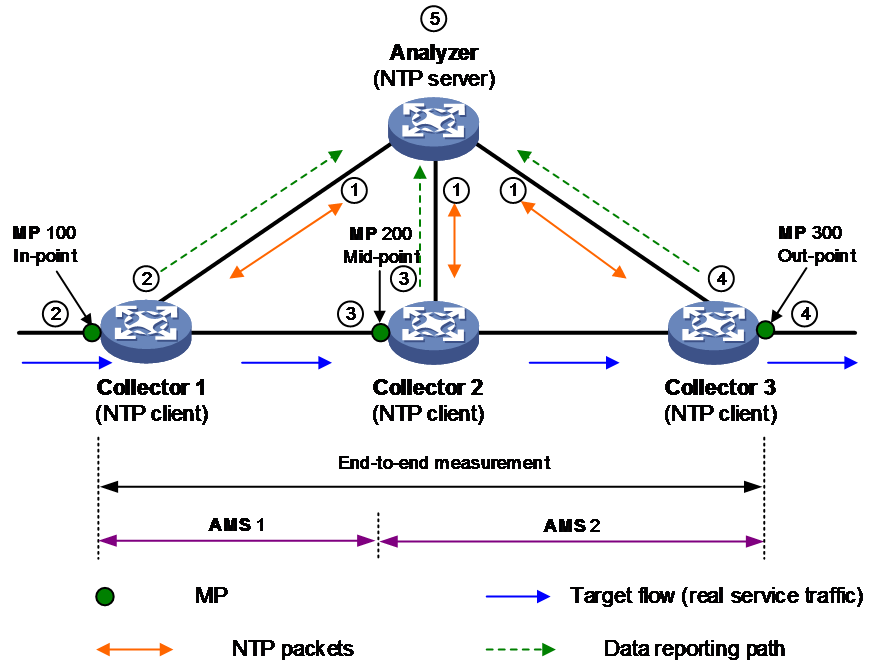
Operating mechanism
As shown in Figure 4, the flow enters the network from MP 100, passes through MP 200, and leaves the network from MP 300. The devices where the flow passes are collectors and NTP clients, and the aggregation device is the analyzer and NTP server.
The iNQA measurement works as follows:
1. The analyzer synchronizes the time with all collectors through the NTP protocol.
2. The ingress MP on collector 1 identifies the target flow. It colors and decolors the packets in the flow alternatively at intervals, and periodically reports the packet statistics to the analyzer.
3. The middle MP on collector 2 identifies the target flow and reports the packet statistics to the analyzer periodically.
4. The egress MP on collector 3 identifies the target flow. It decolors the colored packets and reports the packet statistics to the analyzer periodically.
5. The analyzer calculates packet loss for the flow of the same period and same instance as follows:
Number of lost packets = Number of incoming packets on the MP – Number of outgoing packets on the MP
Packet loss rate = (Number of incoming packets on the MP – Number of outgoing packets on the MP) / Number of incoming packets on the MP
The analyzer calculates the byte loss in the similar way the packet loss is calculated.
For the end-to-end measurement, the data from the ingress MP and egress MP is used:
Packet loss = Number of packets at MP 300 – Number of packets at MP 100
For the point-to-point measurement, the analyzer calculates the result on a per-AMS basis.
· In AMS 1: Packet loss = Number of packets at MP 100 – Number of packets at MP 200
· In AMS 2: Packet loss = Number of packets at MP 200 – Number of packets at MP 300
Restrictions and guidelines
Before configuring iNQA, configure NTP or PTP to synchronize the clocks between the analyzer and all collectors to ensure accurate measurement results.
Application scenarios
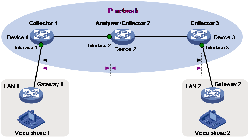
Point-to-point iNQA packet loss measurement
As shown in Figure 5, an erratic video display problem occurs during a video conference between Video phone 1 and Video phone 2. You can use iNQA to measure the packet loss rate in the IP network to confirm whether severe packet loss occurs when the video traffic travels across the IP network and to locate the network faults.
First measure the packet loss rate between Interface 1 and Interface 3. If the packet loss rate is high, divide the flow path into two spans, Interface 1 to Interface 2, and Interface 2 to Interface 3. Measure the packet loss rate on the two spans to locate the faulty network segment.
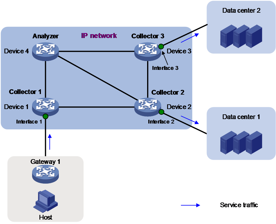
Point-to-multipoint iNQA packet loss measurement
As shown in Figure 6, the data center stores data in Data center 1 and Data center 2 to fulfill load balancing. Data loss occurs after the host saves the data to the data center. The service traffic enters the IP network from Interface 1 and leaves the IP network from Interface 2 and Interface 3. You can deploy iNQA to measure whether packet loss occurs when the service traffic leaves Interface 2 and Interface 3, thus you can locate the network faults.