- Released At: 18-12-2024
- Page Views:
- Downloads:
- Table of Contents
- Related Documents
-
|
|
|
|
|
SyncE Technology White Paper |
|
|
|
|
Copyright © 2021 New H3C Technologies Co., Ltd. All rights reserved.
No part of this manual may be reproduced or transmitted in any form or by any means without prior written consent of New H3C Technologies Co., Ltd.
Except for the trademarks of New H3C Technologies Co., Ltd., any trademarks that may be mentioned in this document are the property of their respective owners.
This document provides generic technical information, some of which might not be applicable to your products.
The information in this document is subject to change without notice.
Contents
Comparison of time synchronization solutions
About automatic clock reference selection
Automatic clock reference selection process
Avoiding timing loops on a direct link
Avoiding timing loops on a ring network
Network frequency synchronization through SyncE
SyncE frequency synchronization + PTP phase synchronization
Overview
Technical background
The correct operation of many services on the communication network requires network time synchronization. Time synchronization includes both frequency synchronization and phase synchronization. The network devices on a network are time synchronized only when their frequency and phase differences are maintained within a reasonable error range.
Network services have different requirements for time synchronization accuracy. Among them, the wireless access service has the highest requirements, requiring that the frequencies of wireless base stations are synchronized within certain accuracy. If the wireless base stations do not reach the synchronization accuracy, the mobile endpoints go offline easily when moving between base stations and might fail to connect to the Internet in severe cases. Table 1 describes the requirements of different wireless technologies for time synchronization accuracy.
Table 1 Requirements of wireless technologies for time synchronization accuracy
|
Wireless technology |
Frequency synchronization accuracy |
Phase synchronization accuracy |
|
GSM |
0.05 ppm |
N/A |
|
WCDMA |
0.05 ppm |
N/A |
|
WiMax FDD |
0.05 ppm |
N/A |
|
LTE FDD |
0.05 ppm |
N/A (except for MB-SFN<+/-1us, LBS) |
|
TD-SCDMA |
0.05 ppm |
+/-1.5 us |
|
CDMA2000 |
0.05 ppm |
+/-3 us |
|
WiMax TDD |
0.05 ppm |
+/-1.5 us+/-1 us |
|
LTE TDD |
0.05 ppm |
+/-1.5 us |
Synchronous Ethernet (SyncE) is a synchronization technology that transfers clock signals over the physical layer. It provides high-precision frequency synchronization between network devices and can meet the requirements of wireless access services for frequency synchronization. SyncE and PTP technologies are typically used together to provide both frequency and phase synchronization and deliver nanosecond-level synchronization accuracy. For information about PTP technology, see PTP Technology White Paper.
Comparison of time synchronization solutions
Synchronous Ethernet (SyncE) can enable only frequency synchronization and is typically used together with PTP. The following table compares SyncE+PTP and other time synchronization solutions, including Global Positioning System (GPS), Beidou Navigation Satellite System (BDS), Network Time Protocol (NTP), and PTP.
Table 2 Comparison of time synchronization solutions
|
Time sync solution |
Frequency sync |
Phase sync |
Sync accuracy |
Description |
|
GPS |
Supported |
Supported |
ns level |
Uses electromagnetic waves to carry frequency and phase information and provides time synchronization. In recent years, the accuracy of GPS has been continuously improved. |
|
BDS |
Supported |
Supported |
ns level |
Uses electromagnetic waves to carry frequency and phase information and provides time synchronization. The BDS network is currently under construction and is expected to provide more ubiquitous, integrated, and smarter navigation, positioning, and timing services by 2035. |
|
NTP |
Not supported |
Supported |
ms level |
Uses NTP messages to transmit phase signals and provides phase synchronization. It is inadequate for scenarios such as wireless access networks that require microsecond-level time synchronization. |
|
PTP |
Supported |
Supported |
Sub-µs level to tens of nanoseconds |
Uses PTP messages to transmit frequency and phase information and combines hardware-based timestamping to deliver high-precision time synchronization. With the development of software and hardware technologies, PTP can bring time synchronization accuracy to tens of nanoseconds level or even better. |
|
SyncE+PTP |
Supported |
Supported |
ns level |
Uses SyncE for frequency synchronization and PTP for phase synchronization, providing faster and more accurate time synchronization than PTP. |
Benefits
Transferring clock signals over the Ethernet physical layer, SyncE is not affected by the upper layer protocols or network conditions such as congestion, packet loss, and delay.
Implementation
Time synchronization basics
Frequency synchronization
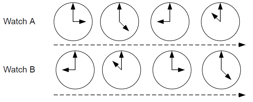
Frequency synchronization is also called clock synchronization. If two signals are the same in frequency or if they keep a constant phase difference, the two signals are frequency synchronized. As shown in Figure 1, the two watches have different time, but maintain a constant time difference (6 hours).
Figure 1 Frequency synchronization
Phase synchronization
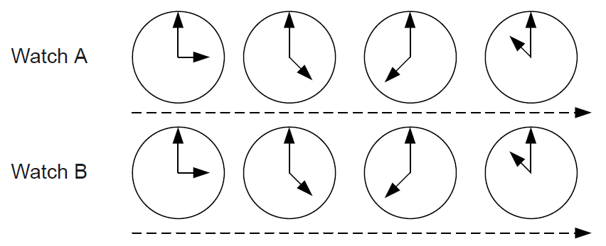
Phase synchronization is also called time synchronization. If two signals are the same in frequency and phase (keep phase difference at 0), they are phase synchronized. As shown in Figure 2, the two watches have the same time at all times. Frequency synchronization is the prerequisite for phase synchronization.
Figure 2 Phase synchronization
Clock sources
SyncE supports the following clock sources:
· BITS—Building integrated timing supply clock. The device has BITS ports to receive and send BITS timing signals.
· Line clock—Timing signal extracted from the signal received on a SyncE-enabled port from a higher-level device. Line timing signal is less precise than BITS timing signal.
· PTP—Timing signal obtained through PTP. PTP timing signal is less precise than BITS timing signal.
· Local clock source—38.88 MHz timing signal generated by a crystal oscillator on the clock daughter card. The local clock signal has the lowest precision.
Clock reference selection
When multiple clock sources are available for the device, you can specify a clock reference manually or configure automatic clock reference selection.
· Manual reference selection—If you specify a clock source as the reference, the device does not change the clock reference automatically. When the signal of the specified clock reference is lost, the device continues to distribute a clock signal based on the parameters of the specified clock reference to the interface cards.
· Automatic reference selection—The system selects the optimal clock automatically as its clock reference. If the signal of the clock reference is lost, the device selects the next optimal clock as its reference and keeps time synchronized with the new reference.
About automatic clock reference selection
In an automatic reference selection process, the device uses the synchronization status message (SSM) quality level and clock source priority to make a selection decision.
SSM quality levels
The SSM, as defined in ITU-T G.781, provides a set of status information to indicate the quality level of the clock source. SyncE also uses SSM levels to indicate the quality of clock sources and names SSM level as QL level. In this paper, the clock source quality level is referred to as SSM level.
The following are the SSM levels in descending order of quality:
· PRC—G.811 primary reference clock. The quality level of a BITS clock tracing GPS or BDS is typically PRC.
· SSU-A—G.812 primary-level SSU. The quality level of a rubidium clock-equipped BITS is typically SSU-A when it enters holdover or free running mode after losing the signal from a satellite source such as GPS.
· SSU-B—G.812 second-level SSU. The quality level of a crystal clock-equipped BITS is typically SSU-B when it enters holdover or free running mode after losing the signal from a satellite source such as GPS.
· SEC/EEC—G.813 SDH equipment clock (SEC)/Ethernet equipment clock (EEC). The quality level of an SEC or EEC is typically SEC/EEC when it enters holdover or free running mode after losing the signal from its clock reference.
· DNU—Do not use for synchronization. The clock sources of this quality level cannot be used as the clock reference.
· Unknown—Synchronization quality unknown.
|
|
IMPORTANT: You can configure whether to use SSM levels in automatic clock reference selection. · If the clock sources are unreliable, you can choose to not use SSM levels in automatic reference selection, or specify SSM levels manually for the clock sources. · If the clock sources are reliable, use SSM levels in automatic clock reference selection as a best practice. |
SSM levels play an important role in automatic selection of an optimal clock and prevention of timing loops. The devices use Ethernet synchronization messaging channel (ESMC) messages to transmit the SSM level of their system clocks.
· After SyncE is enabled on an interface, the device sends an ESMC information message once a second from the interface to inform the neighbor devices of the SSM level of its clock signal.
· When the clock reference selected by the device changes, the device immediately sends an ESMC event message carrying the SSM level of the new clock reference to notify the downstream devices of the change in the SSM level. At the same time, it resets the ESMC information message sending timer, and periodically sends ESMC information messages with the new SSM level to the neighbor devices.
Clock source priority
You can assign a priority to the BITS, PTP, and line clock sources available for the device. The priority is valid locally and will not be passed to neighboring devices.
By default, a clock source has a priority value of 255 and does not participate in clock reference election. For a clock source to participate in clock reference election, assign a priority to it. The smaller the priority value, the better the clock source. Among the clock sources supported by the device, the local clock has the lowest priority and you are not allowed to assign a priority to it.
Automatic clock reference selection process
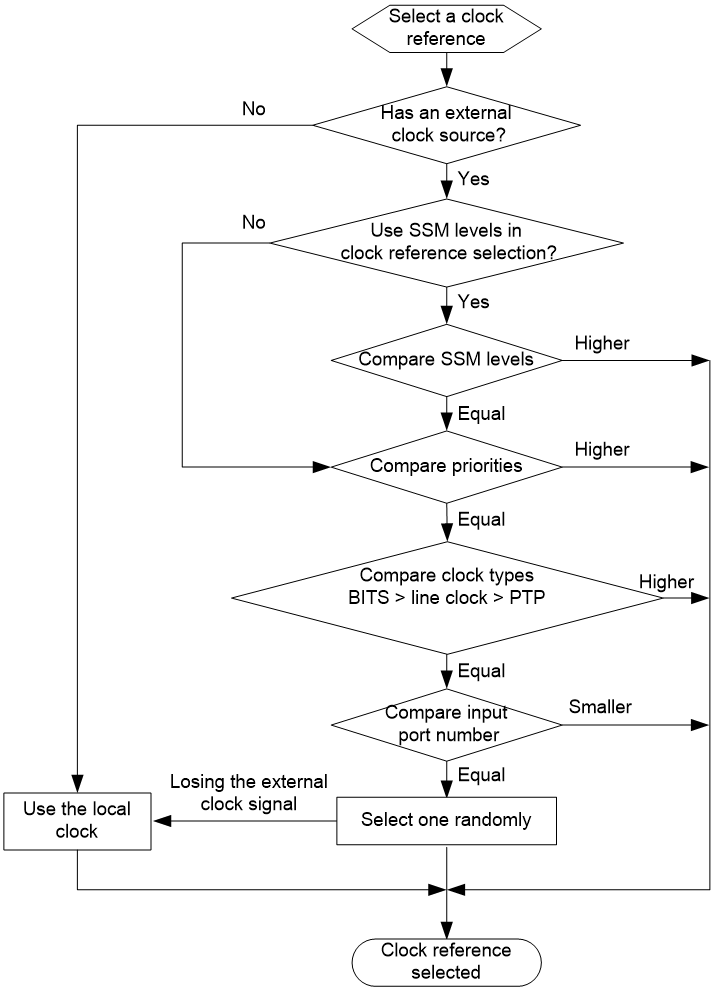
As shown in Figure 3, SyncE uses the following process to select a clock reference:
1. If SSM is enabled for automatic reference selection, the device selects the clock source with the highest SSM quality level.
2. If SSM is disabled for automatic reference selection, or clock sources have the same SSM quality level, the device selects the clock source with the lowest priority value. A lower priority value indicates a better clock source.
3. If the clock sources have the same priority, the device selects the clock source in the sequence of BITS clock source, line clock source, and PTP clock source.
4. If the clock source type is the same, the device selects the clock source that has the lowest number.
5. If no BITS clock source, line clock source, or PTP clock source is available, the device uses the local clock source.
After selecting the clock reference, the device uses ESMC messages to distribute the SSM level of the reference to the downstream devices, which will further affect clock reference selection of the downstream devices.
If an interface on a device does not receive an ESMC information message within 5 seconds after receiving the clock signal from the clock reference, the device determines that the clock reference is lost or unavailable, and will automatically select the next optimal clock as the reference. When the signal of the original clock reference can be traced again, the device selects the original reference to replace the less optimal clock as the reference.
Figure 3 Automatic clock reference selection process
Synchronization mechanism
After selecting the clock reference, the device starts tracing the reference for clock (frequency) synchronization with it.
The Ethernet physical layer uses FE or GE technology to add an additional bit into every fifth bit position. As a result, the data stream transmitted over the Ethernet physical layer will not contain more than four contiguous 1s or 0s and can effectively transmit clock information. With this information transmission mechanism, SyncE sends high-precision clock information from the transmitting end, recovers and extracts the clock signals at the receiving end, and uses the clock information on the receiving end to transmit data streams.
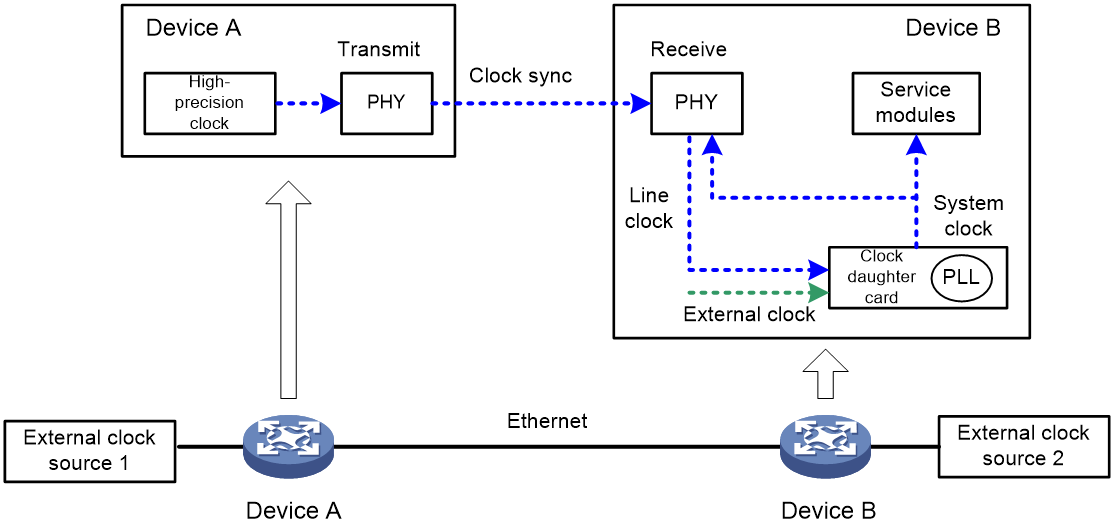
As shown in Figure 4, external clock source 1 is more reliable than external clock source 2 and is selected as the clock reference. Device A and Device B synchronize to the frequency of external clock source 1. The synchronization mechanism is as follows:
· On the transmitting end
a. Among the clock sources available for Device A, external clock source 1 has the highest SSM level. Device A selects external clock source 1 as its clock reference.
b. Device A extracts the clock signal from external clock source 1 and injects the clock signal into the PHY chip on the Ethernet interface card.
c. The PHY chip adds the high-precision clock information into the serial code stream on the Ethernet link and sends it to downstream Device B.
· On the receiving end
a. The PHY chip on the Ethernet interface card on Device B extracts the clock information from the received serial code stream, derives the frequency signal, and then sends it to the clock daughter card.
b. The clock daughter card performs the following tasks:
i Compares the line clock signal received on the interface, the clock signal input from external clock source 2, and the clock signal generated by the local crystal oscillator.
ii Selects the line clock signal as the clock reference based on the automatic source selection algorithm.
iii Sends the clock signal to the PLL.
c. The PLL tracks and synchronizes the system clock with the clock reference. Then it distributes the system clock signal to the service modules of the device and injects the system clock signal into the PHY chip on the Ethernet interface card for distribution to downstream devices.
Figure 4 SyncE clock synchronization mechanism
System clock working mode
The system clock can operate in the following modes. By viewing the system clock working mode, you can understand the clock synchronization status of the device.
· Locked mode—The system has selected a clock reference and keeps frequency synchronized with the reference. In this mode, the clock chip saves data about the clock reference constantly.
· Holdover mode—The system clock has lost the signal from its clock reference and the clock chip continues to provide a clock signal based on the data it has saved about the clock reference for a maximum of 24 hours.
· Free running mode—The device uses the clock signal from the internal crystal oscillator.
Avoiding timing loops
When a network device traces and synchronizes with the clock signal output from itself, a timing loop occurs. A timing loop degrades the clock accuracy and can cause synchronization failure of the entire network. To prevent timing loops, use SSM levels in clock reference selection and plan a reasonable clock synchronization path.
Avoiding timing loops on a direct link
As shown in Figure 5, Device A and Device B are connected to each other directly. Device A sends a clock signal and Device B receives the clock signal. After Device B synchronizes its clock with Device A, it adds clock information to the data packets it will send. If SSM levels are not used in clock reference selection, Device A will synchronize its clock with Device B after receiving data packets from Device B. Then the clock signal will travel along a circular pathway: Device A -> Device B -> Device A, forming a timing loop.
Figure 5 Timing loop on a direct link
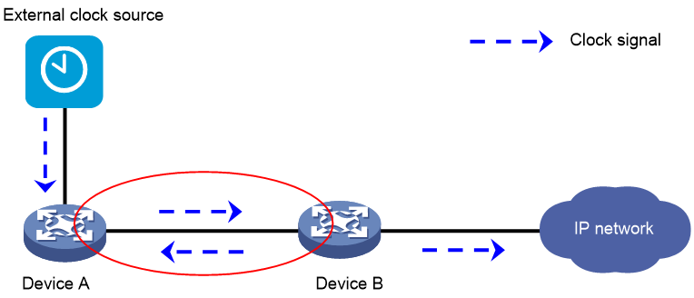
To avoid timing loops, use SSM levels in clock reference selection and set the SSM level to DNU for the ESMC messages sent from Device B to Device A.
Avoiding timing loops on a ring network
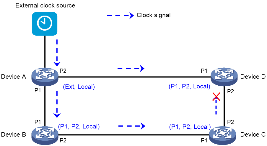
On a ring network, a timing loop can occur easily if the transmission path of the clock signal is not carefully planned. To avoid timing loops on a ring network, use SSM levels in clock reference selection, set the clock priorities manually, and plan a tree or chain transmission path for the clock signal.
As shown in Figure 6, four physical devices form an RRPP ring network, and Device A connects to an external clock source. To use the external clock source as the clock reference of the ring network and Device A instead in case of an external clock source failure, set the clock priorities for the devices as follows:
· Device A—Set a higher priority for the external clock (Ext) than the local clock (Local).
· Device B, Device C, and Device D—Set priorities for line clock input port 1 (P1), line clock input port 2 (P2), and the local clock (Local) in a descending order.
The SyncE clock synchronization path is established as follows:
· Device A receives the signal from the external clock and also the clock signal from Device B on P1. Because the external clock has a higher SSM level than P1, Device A traces and synchronizes with the external clock.
· Device B receives the clock signal from Device A (the clock signal of which is from the external clock) on P1, and also the clock signal from Device C on P2. Because P1 has a higher priority than P2, Device B traces and synchronizes with P1.
· Device C receives the clock signal from Device B on P1, and also the clock signal from Device C on P2. Because P1 has a higher priority than P2, Device C traces and synchronizes with the clock signal from Device B.
· Device D receives the clock signal from Device C on P1, and also the clock signal from Device A on P2. Because P1 has a higher priority than P2, Device D traces and synchronizes with the clock signal from Device C.
· Because P2 on Device A is not configured with a priority, Device A will not synchronize with P2.
Finally, a counter clockwise clock synchronization path from the external clock source to Device D is established. All devices track and synchronize with the external clock source and timing loops are avoided.
Figure 6 Avoiding timing loops on a ring network
Application scenarios
Network frequency synchronization through SyncE
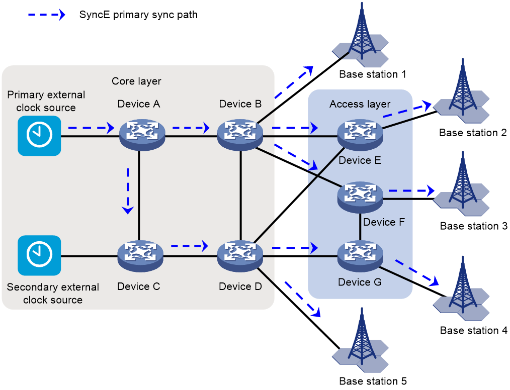
As shown in Figure 7, the wireless base stations use WCDMA technology and access the service provider's network through IP devices. For wireless clients to move smoothly between base stations, enable the neighboring base stations to be frequency synchronized with an accuracy of 0.05 ppm.
· To enhance availability and reduce cost, deploy two clock sources in redundancy at the core layer of the service provider's network.
· Configure SyncE to enable the clock source to synchronize the time of all base stations on the network. Use the primary clock source as the clock reference. Enable the secondary clock source to take over the services automatically when the primary clock source fails. SyncE provides time synchronization among devices with high precision and can meet the requirement of WCDMA wireless access devices for high synchronization precision.
SyncE frequency synchronization + PTP phase synchronization
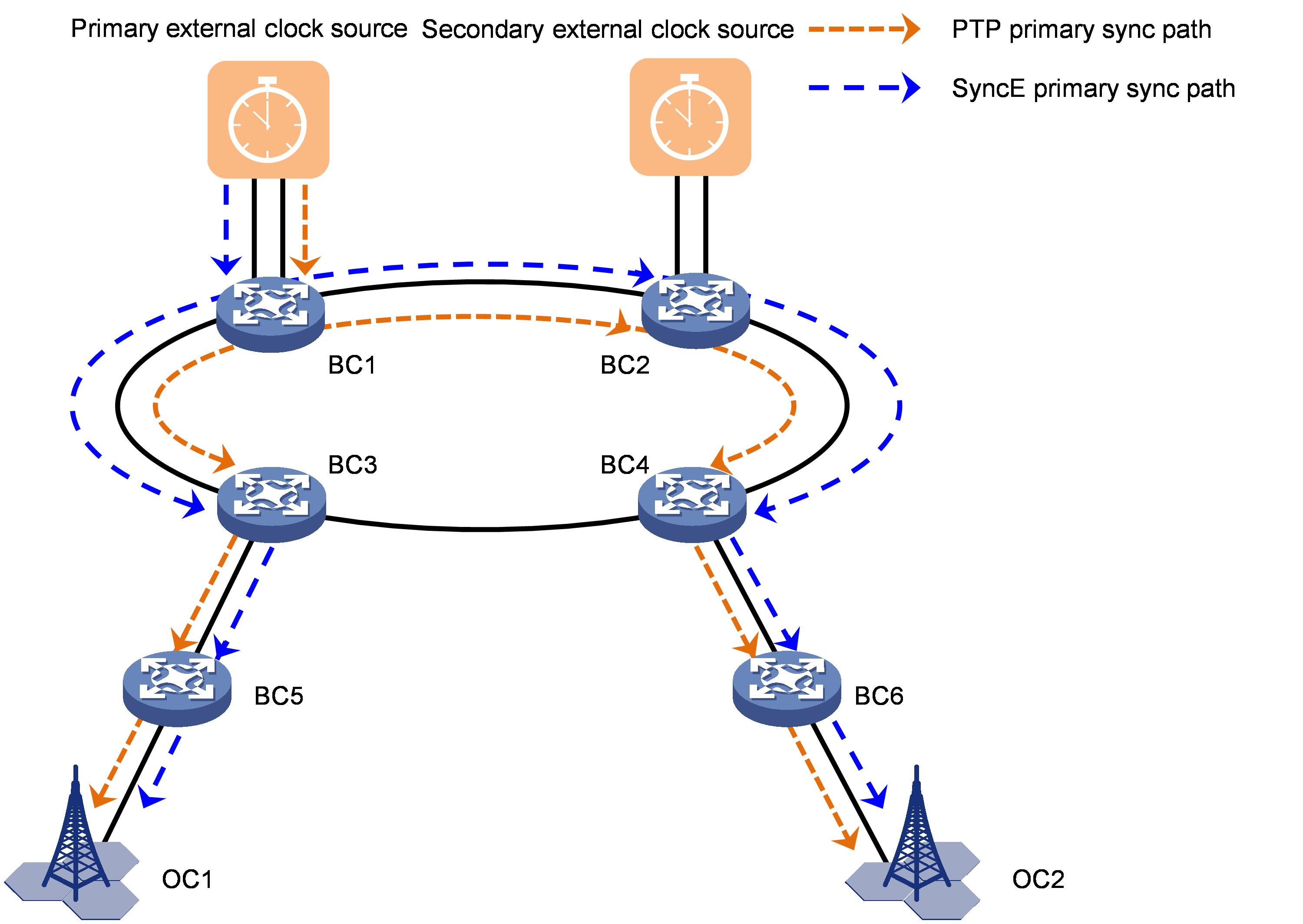
As shown on the 5G access network in Figure 8, the base stations access the service provider's network through IP devices. For wireless clients to move smoothly between base stations, the neighboring base stations must be time synchronized with nanosecond accuracy.
You can use the SyncE frequency synchronization + PTP phase synchronization solution for this scenario. This solution delivers the following advantages:
· Higher accuracy: SyncE can synchronize frequency with nanosecond accuracy, better than PTP.
· Great availability:
¡ Both SyncE and PTP can provide frequency synchronization. The device uses SyncE preferentially for frequency synchronization. If the SyncE clock source fails or the link fails, resulting in frequency synchronization signal loss, the device will use PTP for frequency synchronization.
¡ SyncE and PTP can share clock sources or use independent clock sources. When PTP fails and PTP time signals are lost, SyncE can continue to maintain frequency synchronization between the devices and keep the time offset between the devices within an acceptable range.
References
IEEE 1588-2008, IEEE Standard for a Precision Clock Synchronization Protocol for Networked Measurement and Control Systems
ITU-T G.781, Synchronization layer functions
ITU-T G.811, Timing Characteristics of Primary Reference Clocks
ITU-T G.812, Timing requirements of slave clocks suitable for use as node clocks in synchronization networks
ITU-T G.813, Timing characteristics of SDH equipment slave clocks (SEC)
ITU-T G.823, The control of jitter and wander within digital networks which are based on the 2048 kbit/s hierarchy
ITU-T G.8261, Timing and synchronization aspects in packet networks
ITU-T G.8262, Timing characteristics of a synchronous Ethernet equipment slave clock (EEC)
ITU-T G.8264/Y.1364, Distribution of timing information through packet networks
