- Released At: 18-12-2024
- Page Views:
- Downloads:
- Table of Contents
- Related Documents
-
|
|
|
|
|
MPLS TE FRR Technology White Paper |
|
|
|
|
Copyright © 2021 New H3C Technologies Co., Ltd. All rights reserved.
No part of this manual may be reproduced or transmitted in any form or by any means without prior written consent of New H3C Technologies Co., Ltd.
Except for the trademarks of New H3C Technologies Co., Ltd., any trademarks that may be mentioned in this document are the property of their respective owners.
This document provides generic technical information, some of which might not be applicable to your products.
The information in this document is subject to change without notice.
Contents
Establishment of the primary LSP
Establishment of the bypass LSP
Maintenance of the primary LSP after switchover
Overview
Technical background
MPLS TE networks usually need to be deployed with FRR. This is because of their nature described below:
On a pure IP network, when a route becomes unavailable, packets will be forwarded along other routes (if available) to the same destination. This mechanism allows packets to be serviced before the topology change is advertised throughout the network.
On an MPLS network without TE, LDP downstream unsolicited (DU) mode is often used to establish LSPs. When an LSP goes down, LDP can establish another LSP quickly if there are still routes available. As no TE relevant attributes such as bandwidth, priority, and link attributes are taken into account, a new LSP can be established in most cases and the service can restore in a relatively short period of time.
On an MPLS TE network, LSPs are usually established in DoD mode through RSVP. On a head end, the CSPF algorithm calculates a path based on the routing information of the area that satisfies the constraints and RSVP establishes an LSP along the path. When an element along the LSP fails, a new LSP needs to be established. However, CSPF cannot calculate the path before the head end knows the route change. In addition, a partial failure may make it necessary to reestablish multiple LSPs. During LSP reestablishment, problems such as insufficient bandwidth may intervene. All these add up to the slow restoration from a partial failure of the MPLS TE network. Therefore, compared with pure IP networks and MPLS networks without TE, MPLS TE networks have a higher demand for a quick failure response mechanism.
MPLS TE FRR is intended to meet this demand.
Benefits
MPLS TE FRR is a mechanism for link protection and node protection in MPLS TE. It features quick response and timely switchover, and plays a very important role on MPLS TE networks.
MPLS TE FRR uses a pre-established bypass LSP that does not traverse the protected link or node to protect a primary LSP. After detecting a failure on the protected link or node, MPLS TE FRR can switch the traffic of the primary LSP to the bypass LSP in a very short period of time, thus minimizing data loss. At the same time, the head end of the primary LSP tries to find a new path to reestablish a primary LSP and, after the new primary LSP is established, switches the traffic to the new LSP.
Note that as MPLS TE FRR requires a bypass LSP to be established beforehand to protect a primary LSP, deploying MPLS TE FRR consumes extra bandwidth. Therefore, if the remaining bandwidth is limited, a good practice is to use FRR to protect only the important interfaces.
MPLS TE FRR implementation
Concepts
· Primary LSP: LSP to be protected.
· Backup LSP: LSP used to protect a primary LSP. A backup LSP refers to either a detour LSP or a bypass LSP.
· Detour LSP: LSP used to protect a single primary LSP.
· Bypass LSP: LSP used to protect more than one primary LSP.
· PLR: Ingress of a detour or bypass LSP. It must be on the primary LSP and must not be the egress.
· MP: Egress of a detour or bypass LSP. It must be on the primary LSP and must not be the ingress.
· Link protection: Used when the PLR and MP are connected through a direct link and the primary LSP traverses this link. When the link fails, traffic is switched to the detour or bypass LSP.
· Node protection: Used when the PLR and MP are connected through an LSR and the primary LSP traverses this LSR. When the LSR fails, traffic is switched to the detour or bypass LSP.
Mechanism
MPLS TE FRR uses a pre-established LSP (backup LSP) to protect one or more LSPs (primary LSPs). The purpose of FRR is to reroute the traffic of a failing link or node.
Protected object
MPLS TE FRR can protect links and nodes:
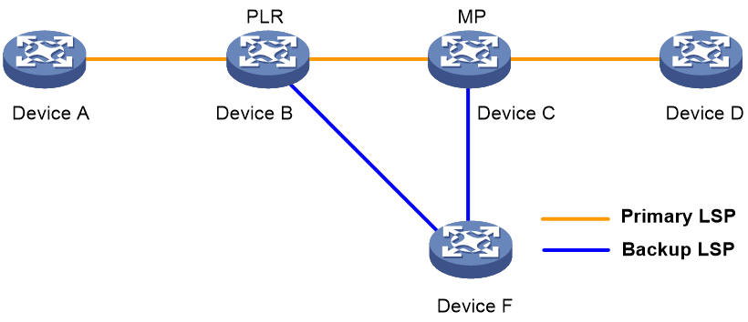
· Link protection: The PLR and MP are connected through a direct link and the primary LSP traverses this link. When the link fails, traffic is switched to the backup LSP. As shown in Figure 1, the primary LSP is Device A → Device B → Device C → Device D, and the backup LSP is Device B → Device F → Device C.
Figure 1 FRR link protection
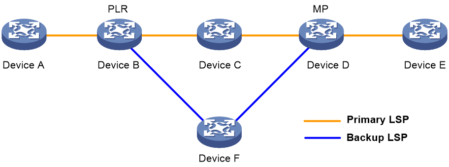
· Node protection: The PLR and MP are connected through a device and the primary LSP traverses this device. When the device fails, traffic is switched to the backup LSP. As shown in Figure 2, the primary LSP is Device A → Device B → Device C → Device D → Device E, and the backup LSP is Device B → Device F → Device D. Device C is the protected device.
Figure 2 FRR node protection
Protection mode
MPLS TE FRR supports two protection modes:
· Detour mode—One-to-one backup mode. In this mode, a backup LSP is established to protect a single primary LSP and the backup LSP is called a detour LSP.
· Bypass mode—Facility backup mode. In this mode, a backup LSP is established to protect more than one primary LSP and the backup LSP is called a bypass LSP.
The detour mode protects each primary LSP with a separate detour LSP and therefore has the disadvantage of high cost. In practice, the bypass mode is widely used. Currently, Comware supports only the bypass mode.
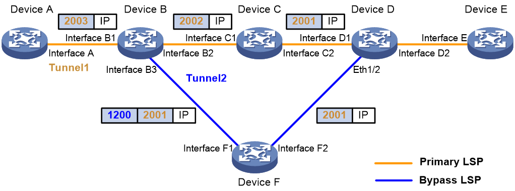
Figure 3 illustrates an example of FRR in bypass mode. The primary LSP is Device A → Device B → Device C → Device D → Device E, and the bypass LSP is Device B → Device F → Device D. When the link from Device B to Device C fails or the node Device C fails, traffic of the primary LSP is switched to the bypass LSP. The following label operations are involved when traffic travels along the bypass LSP:
· For each packet to be forwarded, Device B pushes into the label stack the label that Device D assigned for Device C, and then pushes the label of the bypass LSP, that is, the label that Device F assigned for Device B. In other words, the LSP along the path Device B → Device F → Device D uses two levels of labels.
· When Device D receives the packet, it pops the label that it assigned for Device F and uses the label that it assigned for Device C to forward the packet. Note that if the label that Device D assigned for Device F is an implicit null label, Device F only pops the label that it assigned for Device B; it does not push the implicit null label. In this case, the packet that Device D receives contains only the label that Device D assigned for Device C.
Bypass mode details
MPLS TE FRR establishes protection LSPs by using RSVP TE. The SESSION_ATTRIBUTE and RECORD_ROUTE objects in RSVP messages are extended to implement FRR:
· In the SESSION_ATTRIBUTE object of the PATH message, these flags are used: local protection desired, label recording desired, SE Style desired, and bandwidth protection desired.
· In the RECORD_ROUTE object of the RESV message, four flags are used: local protection available, local protection in use, bandwidth protection, and node protection.
The difference between backup LSP establishment and common LSP establishment lies in the processing of these flag bits.
The following takes Figure 3 as an example to detail MPLS TE FRR in bypass mode:
· Establishment of the primary LSP
· Establishment of the bypass LSP
· Maintenance of the primary LSP after switchover
Establishment of the primary LSP
The establishment process of a primary LSP is almost the same as that of a common LSP, except that a process called binding is involved and several flags and sub-objects are added in the PATH and RESV messages.
Take Figure 3 as an example. The RSVP PATH message travels from the head end (Device A) to the tail end (Device E) hop by hop (Device A → Device B → Device C → Device D → Device E), while the RESV message travels from the tail end to the head end hop by hop. Each visited LSR processes the RESV message and reserves resources for the primary LSP.
The establishment of the primary LSP is initiated by configuring a tunnel manually on the head end. If you configure FRR for the primary LSP before the LSP is established, RSVP will add the local protection desired flag, label recording desired flag, and SE Style desired flag in the SESSION_ATTRIBUTE object of the PATH message. If you also specify the bandwidth of the LSP, RSVP will add another flag called bandwidth protection desired flag. Upon receiving the PATH message, each downstream LSR knows from the local protection desired flag that the LSP needs to be protected by using FRR. In addition, each downstream LSR adds in the RRO of the RESV message the outbound interface of the RESV message, the LSR ID, and the label.
Upon receiving the RESV message for the first time, the LSRs select an appropriate bypass LSP for the primary LSP according to the information recorded in the RRO. This bypass LSP selection process is called binding. For implementation information about binding, refer to Binding calculation.
Establishment of the bypass LSP
When a tunnel without FRR is used to protect an interface, the corresponding LSP becomes a bypass LSP. A bypass LSP can be used to protect multiple interfaces except for its own outbound interface.
The establishment of a bypass LSP (Tunnel 2 on Device B in Figure 3, for example) is initiated by manual configuration on the PLR (Device B). The configuration of a bypass LSP is different from that of a common LSP in two aspects:
· A bypass LSP cannot be configured with FRR. That is, a bypass LSP cannot act as a primary LSP to be protected by another LSP at the same time.
· For a bypass LSP, you need to configure the bandwidth as well as bandwidth protection.
FRR can only be per link or per node. Before configuring a bypass LSP, be sure that you have determined the link or node to be protected and that the bypass LSP will not traverse the link or node to be protected. Otherwise, the bypass LSP cannot protect the primary LSP even if it is established and bound with the primary LSP successfully.
Usually, the bandwidth of a bypass LSP is used for protecting the primary LSPs and all the resources of a bypass LSP are only used after the traffic of its primary LSPs is switched to it. A bypass LSP must have a bandwidth that is equal to or greater than the sum of the bandwidth of all the primary LSPs. If this is not true, some primary LSPs may not be able to be bound with the bypass LSP.
Binding calculation
Binding calculation refers to the process binding a bypass LSP to a primary LSP. The resulting information of binding calculation includes the bypass tunnel interface, NHLFE of the bypass LSP, and label assigned by the MP, which can be used for fast traffic switchover when a local failure occurs. In fact, this is the very reason that MPLS TE FRR can respond to local failures quickly.
Binding calculation must complete before an FRR event can occur. If the binding calculation is successful, RESV will notify the upstream LSR that the primary LSP has been protected.
When multiple bypass LSPs are present for a primary LSP, the following rules are used for selecting the most appropriate one:
· Node protection takes precedence over link protection.
· A bypass LSP whose remaining bandwidth is equal to or greater than the bandwidth of the primary LSP takes precedence over the others.
Failure detection
The aim of failure detection is to find link and node failures and trigger traffic switchover as timely as possible to reduce the traffic service outage as much as possible.
Three methods are available for failure detection:
· Link layer protocol detection: The speed of link layer failure detection depends on the interface type.
· RSVP hello mechanism: With the mechanism enabled on a protected physical interface and its peer interface, hello messages and responses should be sent between the interfaces regularly. Once a link or node failure occurs, hello messages or responses will be lost. If three consecutive messages are lost, it is concluded that a failure has occurred. This mechanism takes more time to find a failure.
· BFD: BFD is a high-speed detection mechanism. It can quickly detect link and node failures.
Switchover process
When a bypass LSP is used instead of a primary LSP, a switchover occurs. After switchover, data of the primary LSP and RSVP messages no longer travel along the original path.
The data to be forwarded is first switched to the bypass LSP. During binding calculation, label 2001, which is the inner label required for data forwarding and the label assigned by the MP, is already saved in the NHLFE and what needs to be done is to flag the LSP as switched. After the flagging, the data is forwarded along the bypass tunnel.
Maintenance of the primary LSP after switchover
After a switchover, the primary LSP is no longer available. To prevent the LSP from being timed out, RSVP sends messages between the PLR (Device B in Figure 3) and the MP (Device D) to maintain the LSP.
The PLR sends a modified PATH message to the MP through the bypass tunnel (Tunnel 2 of Device B). Upon receiving the message, the MP confirms that it is the MP and IP forwards a modified RESV message to the PLR along the path Device D → Device F → Device B.
After switchover, PathTEAR, ResvERR, RescTEAR, and PathERR messages of the primary LSP will travel along a different path.
After switchover, the protected node (Device C) may send a PATHTEAR message to its downstream LSR due to the timeout of the PATH message, but the MP (Device D) will neglect the message. In addition, the MP sends a ResvTear message on the inbound interface of the original LSP (Ethernet 1/3 on Device D) during switchover, so that the protected node (Device C) can release the relevant resources.
Reoptimization
The reoptimization feature periodically calculates paths for an existing LSP. If a better path is found, the LSR establishes a new LSP along the path, switches traffic from the old one to the new one, and then removes the old one.
Reoptimization can be configured for each LSP and starts to function after the LSP is established.
For FRR, reoptimization can make the primary LSP (Tunnel 1 of Device A) restore to normal. As FRR is for temperate protection, reoptimization is usually required for a tunnel configured with FRR. When traffic travels along the primary LSP, a new LSP is established only if the path that the reoptimization feature calculates is not that the primary LSP travels. After traffic has been switched to the bypass LSP, a new LSP is established even if the path that the reoptimization feature calculates is that the primary LSP travels.
Application scenario
MPLS TE FRR can be deployed on key nodes on the network to protect the nodes.
Figure 4 Network diagram for MPLS TE FRR
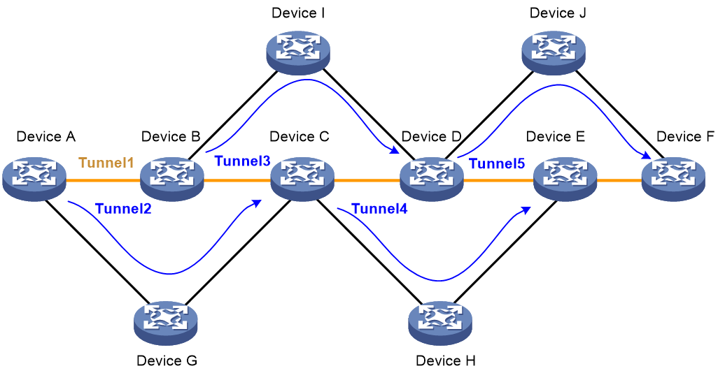
As shown in Figure 4, the service provider provides bandwidth services for users. By connecting users through MPLS TE tunnels, the service provider enables geographically dispersed user networks to communicate through the service provider network. Because the traffic of the users is important, the primary LSP Tunnel 1 needs to be protected. This can be implemented by deploying MPLS TE FRR to use backup LSPs Tunnel 2, Tunnel 3, Tunnel 4, and Tunnel 5 to protect Device B, Device C, Device D, and Device E on the primary LSP respectively.
References
· RFC 3209, RSVP-TE: Extension to RSVP for LSP Tunnels
· RFC 4090, Fast Reroute Extensions to RSVP-TE for LSP Tunnels
· Internet draft “draft-ietf-mpls-nodeid-subobject-01”
