- Released At: 08-05-2025
- Page Views:
- Downloads:
- Table of Contents
- Related Documents
-
|
|
|
HoVPN Technology White Paper |
|
|
|
|
Copyright © 2021 New H3C Technologies Co., Ltd. All rights reserved.
No part of this manual may be reproduced or transmitted in any form or by any means without prior written consent of New H3C Technologies Co., Ltd.
Except for the trademarks of New H3C Technologies Co., Ltd., any trademarks that may be mentioned in this document are the property of their respective owners.
This document provides generic technical information, some of which might not be applicable to your products.
The information in this document is subject to change without notice.
Overview
Background
Because of its capability in providing network connectivity and new services, MPLS L3VPN has become an important tool for service providers to provide value-added services. Though it is actually a basic telecommunication service, the MPLS L3VPN technology still faces many challenges to be addressed, including the performance and scalability problems.
MPLS L3VPN network model
Figure 1 MPLS L3VPN architecture
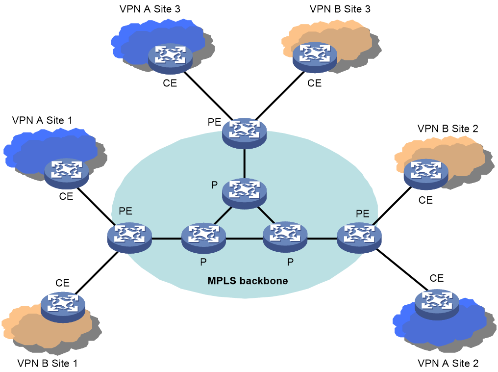
As shown in Figure 1, the flat MPLS L3VPN architecture comprises Provider (P) devices, PEs and CEs.
· P devices: Backbone devices that are not directly connected to any CE. P devices are not aware of the existence of VPNs; they only need to support the basic MPLS forwarding capability.
· PEs: Provider edge devices. Directly connected with users’ CEs, they implement the VPN functions.
· CEs: Customer edge devices. They are customer-side devices that are directly connected with service provider networks. CEs only need to have the ordinary IP forwarding capability.
Among the three categories of devices described above, only PEs are involved in VPN services, which makes PEs shoulder the complete pressure of implementing MPLS L3VPN services. In such a flat architecture, all PEs are equal and need to meet the same performance requirements regardless of their positions in the network. The main problem of the flat architecture is that if some PEs experience performance or scalability problems, the coverage and scalability of the VPN services for the whole network will be affected.
Typical network architectures
So far, two typical network architectures are commonly used: layered network architecture and hierarchical network architecture. The following examines the two architectures for MPLS L3VPN applications.
Typical layered network architecture
Nowadays, the layered network architecture is widely adopted in network design. For example, a typical metropolitan area network (MAN) has three layers: the core layer, the aggregation layer and the access layer. In the direction from the core layer to the access layer, the performance requirement on devices descends, while the layer size increases. Unfortunately, this architecture is not applicable to MPLS L3VPNs.
To provide access services for users, PEs need to have a large number of interfaces. And to process data packets, PEs need to have a large memory capacity and powerful forwarding capability. However, it is not practical for PEs at all layers to possess both high performance and many interfaces at the same time.
· The core layer devices feature high performance but have a limited number of interfaces.
· The access layer devices have large numbers of interfaces but do not provide high performance.
· The aggregation layer devices may fail to meet the requirement for either performance or interface numbers.
As such, scalability is always a problem for the deployment of PEs at any layer, which prevents PEs from expanding to network edge area. The unconformity of the flat architecture of MPLS L3VPN with the layered network architecture is the main cause that restricts the network expansion. The key of the typical layered network architecture is to take full advantage of each layer, such as the high performance of upper layer devices and the access capability of lower layer devices, in order to provide a complete VPN service and to support smooth network upgrade.
Typical hierarchical network architecture
The hierarchical network architecture is the natural choice for many networks. This is because from the perspective of geography and administration, a hierarchical network matches the multiple levels of national, provincial/state, municipal and district. In addition, a single network level (such as the backbone network) can cover only a limited area due to the size limit.
A hierarchical MPLS L3VPN network may span multiple ASs, such as the national backbone, provincial/state backbones, MANs and county-level networks. PE nodes are required at each network to support VPN access. However, performance requirements on PEs vary significantly for different network levels. For example, PEs deployed on a backbone may be core routers or high-end aggregation routers, while PEs in a MAN or county-level network may be mid-range or low-end routers.
Due to the flat topology of MPLS L3VPN, the performance requirements for PEs are the same regardless of the different levels. With the large scale deployment of MPLS L3VPN services, PEs at end networks will face challenges in performance and become the bottleneck.
In addition, the VPN deployment across multiple ASs must be considered in a hierarchical network. The current multi-AS technologies of MPLS L3VPN, such as VPN-instance to VPN-instance, MP-EBGP and MultiHop-EBGP, use a peer structure between ASs, instead of a hierarchical structure. So, they are suitable for the VPN connection among different service providers, rather than for the hierarchy requirements for networks within a service provider.
As the hierarchical network structure is an inevitable trend, how to fit the MPLS L3VPN network architecture into a hierarchical network to improve scalability and to implement the multi-AS hierarchical structure has become an urgent issue.
MPLS L3VPN defects
To summarize, among the defects of the current MPLS L3VPN architecture, the main problem is the flat structure which cannot meet the requirements of layered or hierarchical network model. From that the following issues arise:
· The service coverage is limited; the operation cost cannot be reduced; the MPLS L3VPN service cannot be deployed in large scale and the end-to-end high value services are restricted.
· The network is not scalable. Therefore, MPLS L3VPN services cannot be expanded to network edge areas, which is not good for service upgrade and investment protection.
· The flat structure cannot make full use of different network layers, and therefore requires high-end PEs, which increase the network construction cost.
Hence, it has become imperative to optimize the MPLS L3VPN network architecture.
Benefits
To solve the scalability problem in layered and hierarchical network architectures, the hierarchical architecture solution for MPLS L3VPN networks is designed. The architecture is designed with the following considerations:
· Classifying PEs into multiple levels and having the PEs to implement the functions of a traditional PE.
· Deploying PEs with higher capacity and performance at higher network levels.
· Deploying more PEs with higher access capability at lower network levels.
· Ensuring that the network architecture can support unlimited, hierarchical expansion.
· Ensuring that the network architecture can support multi-AS connections.
The hierarchy of VPN (HoVPN) solution for MPLS L3VPN networks can classify PEs into an arbitrary number of levels to achieve unlimited expansion. It distributes the PE function among various PEs with different roles in a hierarchical structure. Devices at higher levels should have higher routing and forwarding capabilities, while devices at lower levels can have lower capabilities, which matches the typical hierarchical network model.
HoVPN implementation
Fundamental architecture of HoVPN
Figure 2 Fundamental architecture of HoVPN
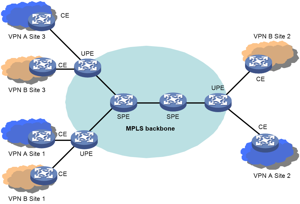
As shown in Figure 2, in the HoVPN architecture, PEs directly connected with CEs are called under-layer PEs or user-end PEs (UPEs), and PEs connecting UPEs and residing in the inner area of the network are called super-stratum PEs or service provider-end PEs (SPEs). An SPE and the connected UPEs form a hierarchical PE structure, which provides the same functions as a traditional PE.
HoVPN includes the following components:
· VPN instance—In an MPLS L3VPN network, route segregation among different VPNs is implemented by VPN instances. A PE establishes and maintains a separate VPN instance for each directly connected site and each VPN instance has a separate routing table and forwarding table.
· VPN site—A VPN site is an independent IP network within a VPN and it can belong to one or more VPNs. A VPN site is identified by its RD.
· UPE—PEs directly connected with CEs.
· SPE—PEs connecting UPEs and residing in the inner area of the network.
SPE and UPE
The main function of a UPE is to connect users. It maintains only routes to its directly connected VPN sites or the aggregated routes to remote VPN sites. It does not maintain routes to individual remote VPN sites. A UPE assigns inner labels for routes to its directly connected sites, and advertises the labels to the SPE through MP-BGP.
The main function of an SPE is to maintain and propagate VPN routes. It needs to maintain all VPN routes, including routes of both the local and remote sites. An SPE advertises routes with labels to UPEs. The routes advertised can be default routes (or aggregated routes) of VPN instances, or routes permitted by routing policies. Access control of sites within a VPN is implemented by routes permitted by routing policies.
The different functions of SPE and UPE embody the characteristics of PEs at different levels. An SPE has a large capacity for routing entries and has a powerful forwarding capability, but provides just a few interfaces; UPEs do not have high routing and forwarding performance but are large in number, enabling them to connect many users at places near to users. The HoVPN technology makes full advantage of the performance of SPE and the access capability of UPE.
Note that UPE and SPE are relative concepts. In an architecture with multiple PE levels, a mid-level PE is an SPE to its lower level PEs, and is a UPE to its upper level PEs.
From the appearance, a hierarchical PE structure has no difference from a traditional PE. Therefore, it can coexist with traditional PEs in the same MPLS network.
Protocol between SPE and UPE
Between SPE and UPE runs the MP-BGP protocol, which can be MP-IBGP or MP-EBGP, depending on whether the SPE and UPEs are in the same AS.
Evolution of HoVPN
Figure 3 Evolution of the HoVPN layered network
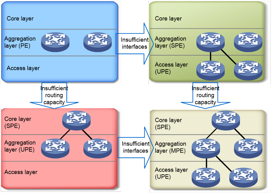
As shown in Figure 3, PEs are initially deployed at only the aggregation layer. When the quantity of interfaces is not enough, some PEs are added at the access layer, acting as UPEs, while the PEs at the aggregation layer act as SPEs. When the routing capacity is insufficient, some other PEs are deployed at the core layer to function as SPEs, while PEs at the aggregation layer become UPEs. When PEs are deployed at all of the tree layers, a three-layer architecture comes into being and the PEs at the aggregation layer become the Middle-level PEs (MPEs). Such evolution is very suitable for a MAN.
Application scenarios
HoVPN network extension
Figure 4 HoVPN network extension
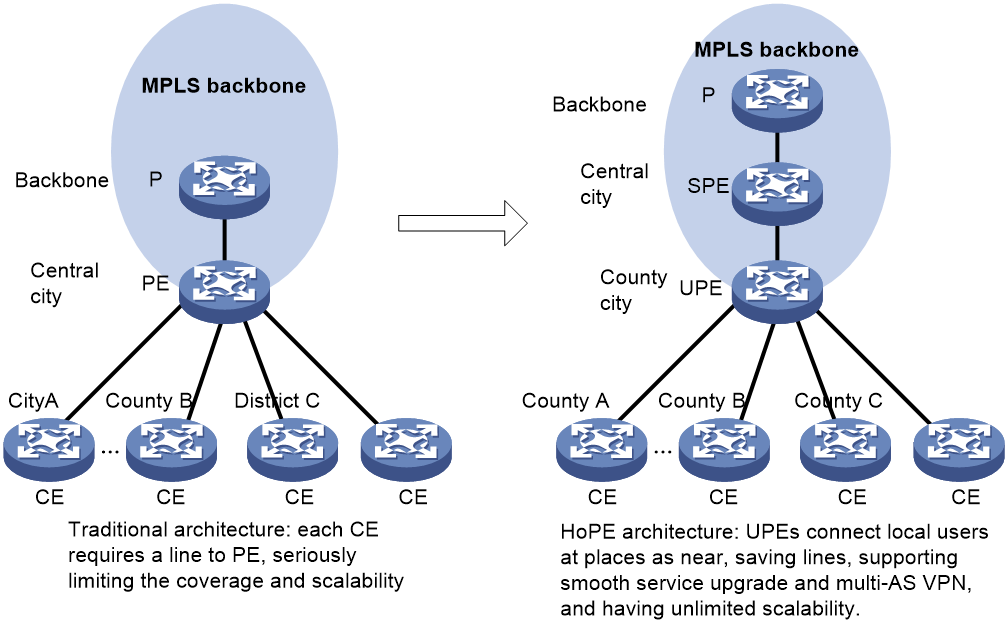
As shown in Figure 4, an MPLS L3VPN network deployed nationwide usually adopted the flat network architecture, providing MPLS L3VPN services directly through the backbone. In this scenario, backbone PEs usually reside at central cities and each CE is connected to a PE by a separate line.
This method has native drawbacks. First, remote CEs require large quantities of wide area network (WAN) line resources to access the central city nodes. Second, the backbone size and the coverage and scalability of the whole network are greatly restricted.
With HoVPN, UPEs can be deployed at smaller cities and even counties to connect local VPN users nearby. At the same time, the network coverage and scalability are enhanced, and new services can be achieved as needed. An SPE and its UPEs may or may not be in the same AS.
Multi-AS deployment of HoVPN
Figure 5 Multi-AS deployment of HoVPN
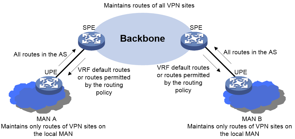
As shown in Figure 5, the backbone and MANs are in different ASs. In this case, SPEs can be deployed in the backbone and UPEs can be deployed in the MANs. Each UPE sends all routes of its MAN to its SPE, while the SPE advertises to the UPE the default routes of VPN instances or routes permitted by the routing policy. As a result, each MAN only needs to maintain routes of its local VPN sites, and the backbone maintains routes of all VPN sites.
In the multi-AS deployment, flexible approaches such as VPN-OptionB or VPN-OptionC can be used between SPE and UPE.
The multi-AS deployment of HoVPN meets the requirements of the hierarchical network architecture. The high-level network (backbone) handles the global services, while low-level networks (MANs) handle local services. This architecture avoids the capacity and scalability problems in low-level networks arising from the expansion of global VPN services.
