- Released At: 08-11-2024
- Page Views:
- Downloads:
- Table of Contents
- Related Documents
-
|
|
|
H3C Switches DR System Upgrade, Replacement, and Expansion Guide |
|
|
|
|
|
|
Document version: 6W102-20221118
Copyright © 2022 New H3C Technologies Co., Ltd. All rights reserved.
No part of this manual may be reproduced or transmitted in any form or by any means without prior written consent of New H3C Technologies Co., Ltd.
Except for the trademarks of New H3C Technologies Co., Ltd., any trademarks that may be mentioned in this document are the property of their respective owners.
This document provides generic technical information, some of which might not be applicable to your products.
The information in this document is subject to change without notice.
Contents
Compatible hardware and software
Viewing the current software version
Setting up the upgrade environment and transferring the upgrade file to the device
Disconnecting the DR member devices from a controller (in a controller-based environment)
Restoring network connections on the member device
Upgrading the other member device
Restoring the controller connection (in a controller-based environment)
Rolling back the DR system (in a controller-based environment)
Replacing a faulty device by performing a standard upgrade
Transferring the configuration file of the faulty device to the replacement device
Upgrading the replacement device
Shutting down all the physical interfaces of the replacement device
Disconnecting the faulty device
Replacing the faulty device and connecting the replacement device to the network
Bringing up physical interfaces on the replacement device
Verifying service states on the replacement device
Restoring the controller connection (in a controller-based environment)
Disconnecting the DR member devices from a controller (in a controller-based environment)
Saving the running configuration
Specifying upgrade files and rebooting the member device
Upgrading the other member device
Restoring the controller connection (in a controller-based environment)
Rolling back the DR system (in a controller-based environment)
Replacing a faulty device by performing a graceful upgrade
Transferring the configuration file of the faulty device to the replacement device
Upgrading the replacement device
Disconnecting the replacement device
Disconnecting the faulty device
Connecting the replacement device to the network
Powering on the replacement device or bringing up the physical interfaces
Switching to normal mode on the replacement device
Verifying service states on the replacement device
Restoring the controller connection (in a controller-based environment)
Replacing a service module (in a modular device-based environment)
Replacing a service module without IPP member ports or keepalive link ports
Replacing a service module with IPP member ports
Replacing a service module with keepalive link ports
About DR system upgrade
Distributed Resilient Network Interconnect (DRNI) virtualizes two physical devices into one system through multichassis link aggregation to provide node redundancy in addition to link redundancy.
In addition to the benefits of link aggregation, such as high bandwidth, link redundancy, and load sharing, DRNI also provides service continuity during software upgrade of one member in the multichassis link aggregation system.
This document introduces the following upgrade methods:
· Standard upgrade.
· Graceful upgrade. Use this method on GIR-capable devices.
|
|
NOTE: Graceful insertion and removal (GIR) enables you to gracefully isolate the device from the network for device maintenance or upgrade. GIR minimizes service interruption by instructing the affected protocols (for example, routing protocols) to isolate the device and switch over to the redundant path. You do not need to configure graceful switchover protocol by protocol. For more information about GIR, see the fundamentals configuration guides or release notes for the devices. |
DR system upgrade methods
Standard upgrade
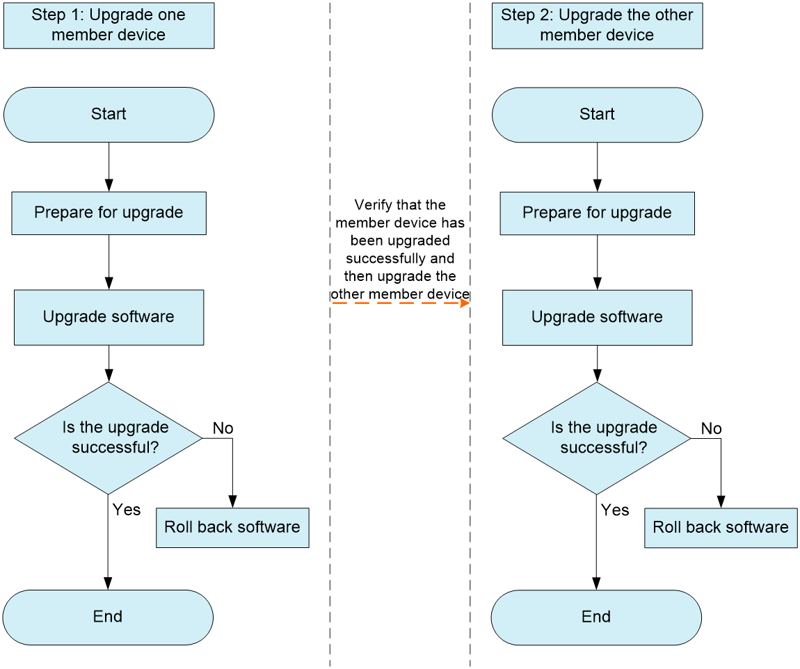
To perform a standard upgrade, upgrade the DR member devices one by one. All DRNI-capable device models support the standard upgrade method.
As shown in Figure 1, you can upgrade the DR member devices in any order. The impact of the upgrade on services does not differ whether you upgrade the primary or secondary device first. If you upgrade the secondary device first, the roles of the DR member devices are switched after the upgrade.
Figure 1 Standard upgrade process
Graceful upgrade
Upgrade process
This upgrade method guarantees zero packet loss during an upgrade except in scenarios where single-homed devices.
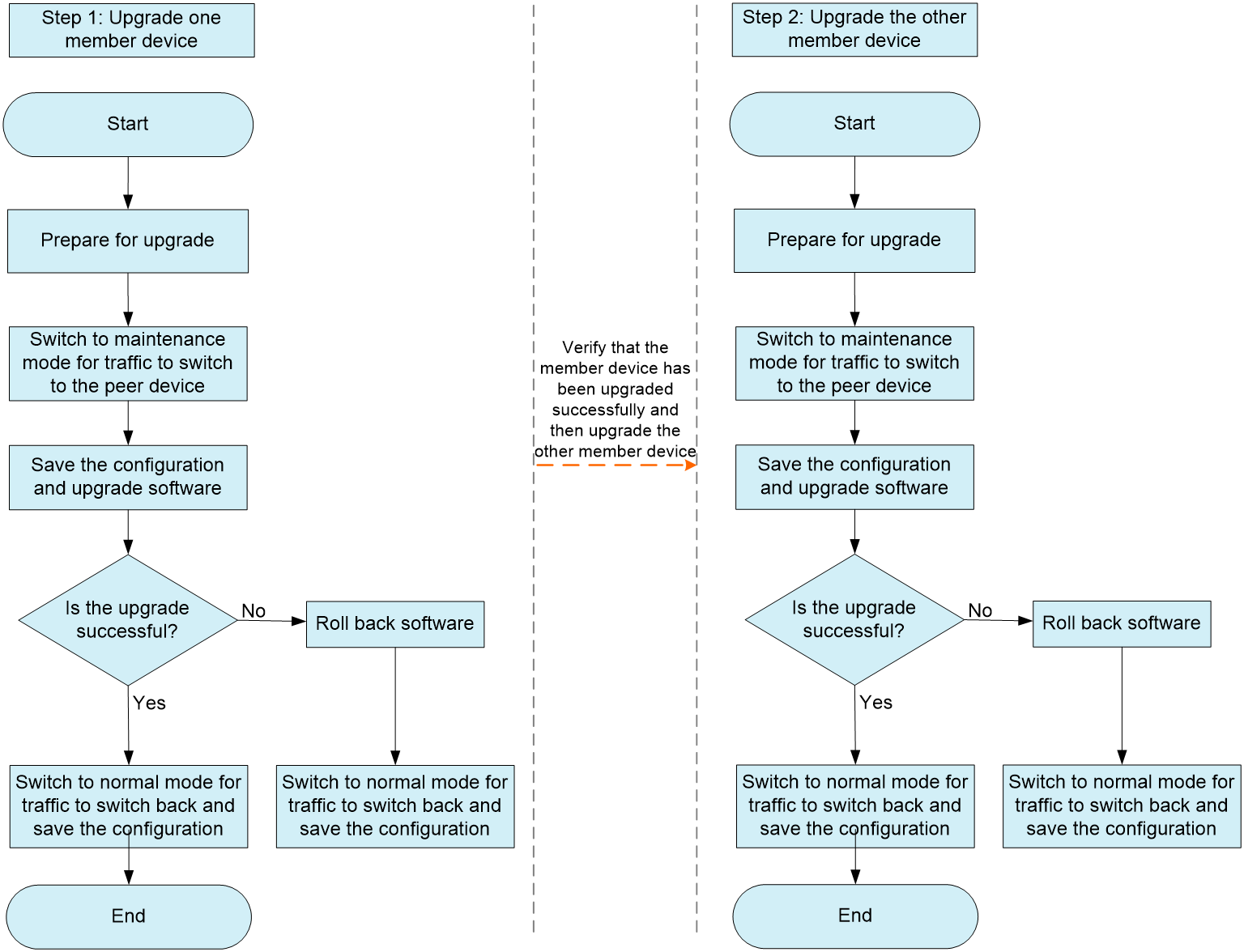
In a graceful upgrade, the DR member devices are also upgraded one by one. Unlike a standard upgrade, a graceful upgrade requires you to place a DR member device in maintenance mode before you upgrade it. After the DR member device is upgraded, you must place it in normal mode.
As shown in Figure 2, you can upgrade the DR member devices in any order. The impact of the upgrade on services does not differ whether you upgrade the primary or secondary device first. If you upgrade the secondary device first, the roles of the DR member devices are switched after the upgrade.
Figure 2 Graceful upgrade process
Benefits
With spanning tree disabled, a standard upgrade interrupts traffic for 500 ms or shorter except in scenarios where single-homed devices are attached. However, with spanning tree disabled a graceful upgrade guarantees non-stop forwarding of east-west overlay traffic and north-south underlay traffic at the leaf tier.
|
|
NOTE: The convergence time for STP state switching might takes about dozens of seconds. In a spanning tree network, to speed up the convergence, you can execute the stp edged-port or undo stp enable command in the following situations: · The peer is a server or a Layer 3 interface. · The peer is a switch or firewall that has no loop risk. |
Compatible hardware and software
A graceful upgrade requires the DR member devices to support GIR. Table 1 shows the hardware and software support for GIR.
Table 1 Hardware and software support for GIR
|
Hardware |
Software |
Comware branch |
|
S12500X-AF, S12500F-AF |
F2805 or later |
B70D042SP |
|
S12500G-AF, S12500-XS, S10500X, S7600, S7600E-X, S7500X |
R7624P0x or later |
B70D064SP |
|
S6890 |
F2805 or later |
B70D042SP |
|
S6805, S6850, S9850 |
F6623 or later |
B70D047SP |
|
S9820-8C |
F6631 or later |
B70D047SP |
|
S6550XE-HI, S6525XE-HI |
ESS 6103L03 |
B70D064SP |
Preparing for an upgrade
|
|
NOTE: · This document uses the command output from the S6850 switch series for demonstration. The command output varies by device model. · To facilitate viewing and recording of the command output, you can execute the screen-length disable command in user view to disable pausing between screens of output. |
Verifying the device state
Viewing the current software version
Execute the display version command to view the current software version.
<Sysname> display version
H3C Comware Software, Version 7.1.070, Feature 6632
Copyright (c) 2004-2021 New H3C Technologies Co., Ltd. All rights reserved.
H3C S6850-56HF uptime is 0 weeks, 4 days, 1 hour, 44 minutes
Last reboot reason : User reboot
Verifying system states
Perform the following tasks:
· Execute the display device command to verify that the device is operating correctly.
<Sysname> display device
Slot Type State Subslot Soft Ver Patch Ver
1 S6850-56HF Master 0 S6850-56HF-6632 None
· Execute the display system stable state command to verify that the device is stable.
<Sysname> display system stable state
System state : Stable
Redundancy state : No redundancy
Slot CPU Role State
1 0 Active Stable
· Execute the display memory command and record the memory usage.
<Sysname> display memory
Memory statistics are measured in KB:
Slot 1:
Total Used Free Shared Buffers Cached FreeRatio
Mem: 8090436 1633592 6456844 0 3672 187888 79.8%
-/+ Buffers/Cache: 1442032 6648404
Swap: 0 0 0
· Execute the display cpu-usage command and record the CPU usage.
<Sysname> display cpu-usage
Slot 1 CPU 0 CPU usage:
1% in last 5 seconds
1% in last 1 minute
1% in last 5 minutes
Verifying DR system states
Perform the following tasks:
· Execute the display drni summary command to verify that DRNI is operating correctly.
<Sysname> display drni summary
Flags: A -- Aggregate interface down, B -- No peer DR interface configured
C -- Configuration consistency check failed
IPP: BAGG1
IPP state (cause): UP
Keepalive link state (cause): UP
DR interface information
DR interface DR group Local state (cause) Peer state Remaining down time(s)
BAGG2 2 UP UP -
BAGG3 3 UP UP -
· Execute the display drni keepalive command to verify that the keepalive link is operating correctly.
<Sysname> display drni keepalive
Neighbor keepalive link status: Up
Neighbor is alive for: 135642 s 501 ms
Keepalive packet transmission status:
Sent: Successful
Received: Successful
Last received keepalive packet information:
Source IP address: 10.0.0.2
Time: 2021/12/11 09:21:51
Action: Accept
Distributed relay keepalive parameters:
Destination IP address: 10.0.0.2
Source IP address: 10.0.0.1
Keepalive UDP port : 6400
Keepalive VPN name : vpn1
Keepalive interval : 1000 ms
Keepalive timeout : 5 sec
Keepalive hold time: 3 sec
· Execute the display drni role command to verify that the DR role of the device is correct.
<Sysname> display drni role
Effective role information
Factors Local Peer
Effective role Primary Secondary
Initial role None None
MAD DOWN state Yes Yes
Health level 0 0
Role priority 32768 32768
Bridge MAC 3cd4-3ce1-0200 3cd4-437d-0300
Effective role trigger: IPL calculation
Effective role reason: Bridge MAC
Configured role information
Factors Local Peer
Configured role Primary Secondary
Role priority 32768 32768
Bridge MAC 3cd4-3ce1-0200 3cd4-437d-0300
· Execute the display drni system command to verify that the DR system parameters are correct.
<Sysname> display drni system
System information
Local system number: 1 Peer system number: 2
Local system MAC: 0001-0001-0001 Peer system MAC: 0001-0001-0001
Local system priority: 123 Peer system priority: 123
Local bridge MAC: 3cd4-3ce1-0200 Peer bridge MAC: 3cd4-437d-0300
Local effective role: Primary Peer effective role: Secondary
Health level: 0
Standalone mode on split: Enabled
In standalone mode: No
System timer information
Timer State Value (s) Remaining time (s)
Auto recovery Disabled - -
Restore delay Disabled 300 -
Consistency-check delay Disabled 15 -
Standalone delay Disabled - -
Role to None delay Disabled 60 -
Checking device configuration
Verify that the data restoration interval configured by the drni restore-delay command is appropriate. If the interval is too short, after the restart, the DR member device will bring up all network interfaces before it synchronizes table entries. This will cause packet loss. For information about how to configure the data restoration interval, see the DRNI configuration guide for the device.
For modular devices with two MPUs, to reduce service interruption time during the upgrade, you can configure nonstop routing (NSR) before the upgrade.
Checking the flash memory
1. Execute the dir command to verify that the flash memory has sufficient space to save the target images.
<Sysname> dir
Directory of flash:
0 -rw- 80264 DEC 11 2021 00:33:57 startup.mdb
1 -rw- 3523 DEC 11 2021 00:33:56 startup.cfg
2 -rw- 9959424 DEC 11 2021 16:04:08 boot.bin
3 -rw- 53555200 DEC 11 2021 16:04:08 system.bin
4 drw- - DEC 11 2021 00:03:07 seclog
5 drw- - DEC 11 2021 00:03:07 versionInfo
6 -rw- 91273216 DEC 11 2021 09:54:27 backup.bin
1048576 KB total (897252 KB free)
2. If the flash memory does not have sufficient space, delete undesired files by executing the delete /unreserved flash:/filename command in user view.
Verifying service states
Execute the commands in the following matrix to verify that the MAC address table, ARP table, routing neighbor, routing table, and FIB entries are correct.
|
Command |
Description |
|
display mac-address |
Display MAC address entries. |
|
display arp |
Display ARP entries. |
|
display ipv6 neighbors |
Display IPv6 neighbors. |
|
display ip interface brief |
Display IP addresses of Layer 3 interfaces. |
|
display ospf peer |
Display OSPF neighbors. |
|
display ospfv3 peer |
Display OSPFv3 neighbors. |
|
display bgp peer ipv4 |
Display BGP IPv4 peers. |
|
display bgp peer ipv6 |
Display BGP IPv6 peers. |
|
display isis peer |
Display IS-IS neighbors. |
|
display ip routing-table display ip routing-table all-routes display ipv6 routing-table display ipv6 routing-table all-routes |
Display routing information. |
|
display fib display ipv6 fib |
Display FIB entries. |
|
display vrrp display vrrp ipv6 |
Display VRRP group status. |
|
display current-configuration |
Display the running configuration. |
Preparing upgrade files
Prepare startup files, patch images, and a configuration file.
Startup files
Startup files provide hardware drivers and service features. Startup files include the following:
· Boot image—A file that contains the operating system kernel. It provides process management, memory management, file system management, and the emergency shell.
· System image—A file that contains required and standard features, including device management, interface management, configuration management, and routing.
Software images are released in one of the following forms:
· Separate .bin files.
· As a whole in one .ipe package file. The images in an .ipe package file are compatible
|
|
NOTE: The S6850 switch series uses an .ipe package that contains the image files and the BootRom file. If you specify an .ipe package as the next-startup file, the device will automatically extract all .bin files from the package and load them at the next startup. |
Patch images
A patch image is released for fixing bugs without rebooting the device.
Configuration file
A configuration file saves a set of commands for configuring software features on the device. You can save any configuration to a configuration file so the configuration can survive a reboot. You can also use configuration files to bulk configure devices.
Preparing tools
Prepare the following tools:
· An endpoint for accessing the device.
· An Ethernet network cable and a console cable.
· FTP Server, SFTP Server, or TFTP Server software.
The software is not provided with the device. You need to purchase and install the software on the endpoint.
Setting up the upgrade environment and transferring the upgrade file to the device
1. Connect the endpoint to the device with cables.
¡ Use the console cable to connect the serial port of the endpoint to the console port of the device.
¡ Use the Ethernet network cable to connect the network port of the endpoint to the management Ethernet interface of the interface.
2. Transfer the upgrade file to the device through FTP, SFTP, or TFTP.
3. Execute the md5sum command in user view to calculate the digest of the upgrade file and identify whether the digest is consistent with the value of the MD5 file during the release process:
¡ If the digest and the value of the MD5 file are consistent, the upgrade file is correct and complete.
¡ If the digest and the value of the MD5 file are not consistent, you must download the upgrade file again.
Performing a standard upgrade
Disconnecting the DR member devices from a controller (in a controller-based environment)
1. If the DR member devices are connected to a controller, disconnect them from the controller.
2. Execute the display openflow instance instance-id controller command to verify that the controller is disconnected.
[Sysname] display openflow instance 1 controller | include state
Connect state : Idle
Connect state : Idle
Upgrading one member device
Specifying upgrade files
1. Specify the target .ipe package as a next-startup file.
<Sysname> boot-loader file flash:/s9850_6850-f6633.ipe all main
2. Verify that the .ipe package will be loaded at the next startup.
<Sysname> display boot-loader
Software images on slot 1:
Current software images:
flash:/s9850_6850-cmw710-boot-f6632.bin
flash:/s9850_6850-cmw710-system-f6632.bin
Main startup software images:
flash:/s9850_6850-cmw710-boot-f6633.bin
flash:/s9850_6850-cmw710-system-f6633.bin
Backup startup software images:
None
Isolating the member device
Perform one of the following tasks:
· Shut down the physical interfaces in the following order:
a. Downlink service interfaces.
b. Uplink service interfaces.
c. Physical interface used for setting up the keepalive link.
d. Physical member ports of the IPP.
· Shut down all physical interfaces by interface range or power off the device in scenarios insensitive to service interruption.
Do not shut down logical interfaces such as aggregate, VLAN, tunnel, and VSI interfaces.
Rebooting the member device
Execute the reboot command to reboot the member device.
<Sysname> reboot
Start to check configuration with next startup configuration file, please wait.........DONE!
Current configuration may be lost after the reboot, save current configuration? [Y/N]:y -----Enter y to save the configuration.
Please input the file name(*.cfg)[flash:/drni_old.cfg]
(To leave the existing filename unchanged, press the enter key):startup.cfg
Validating file. Please wait...
Saved the current configuration to mainboard device successfully.
This command will reboot the device. Continue? [Y/N]:y --------Enter y to reboot the device.
Verifying the upgrade result
1. Verify that the member device has been upgraded to the target version.
<Sysname> display boot-loader
Software images on slot 1:
Current software images:
flash:/s9850_6850-cmw710-boot-f6633.bin
flash:/s9850_6850-cmw710-system-f6633.bin
Main startup software images:
flash:/s9850_6850-cmw710-boot-f6633.bin
flash:/s9850_6850-cmw710-system-f6633.bin
Backup startup software images:
None
2. Execute the display device command to verify that the member device is operating correctly.
<Sysname> display device
Slot Type State Subslot Soft Ver Patch Ver
1 S6850-56HF Master 0 S6850-56HF-6633 None
3. Verify that the configuration has been restored:
¡ Execute the display current-configuration command in any view to verify that the configuration has been restored to the state before the upgrade.
¡ Execute the display diff current-configuration configfile flash:/XXX.cfg command in any view to verify that the current configuration file is not lost or changed.
Restoring network connections on the member device
If you have shut down the physical interfaces one by one or by interface range before the upgrade, bring up the physical interfaces in the following order:
1. Physical member ports of the IPP.
2. Physical interface used for setting up the keepalive link.
3. Uplink service interfaces.
4. Downlink service interfaces.
After you bring up the member ports of the IPP, the DR system is set up. Service interfaces can come up only after the data restoration interval configured by the drni restore-delay command expires. As a best practice, bring up the service interfaces after the data restoration interval expires.
If you have powered off the device before the upgrade, skip this step.
Verifying service states
1. Perform one of the following tasks:
¡ Display forwarding entries such as routing, FIB, and MAC address entries to verify that they are not lost during the upgrade and that service flows are the same as before the upgrade. Verify that the memory usage and CPU usage of the device do not change greatly before and after the upgrade.
¡ Verify with the O&M team that the services and servers attached to the device are operating correctly.
2. If services are abnormal, roll back the software and check service states again to restore abnormal services.
Upgrading the other member device
Upgrade the other member device as described in "Upgrading one member device."
If services are abnormal after the upgrade, roll back the software on the DR member devices in the reverse order of their upgrade.
Restoring the controller connection (in a controller-based environment)
1. Connect the primary and secondary devices to the controller.
2. Execute the display openflow instance instance-id controller command to verify that the controller is connected.
[Sysname] display openflow instance 1 controller | include state
Connect state : Established
Connect state : Established
Rolling back the DR system (in a controller-based environment)
If the services are abnormal after you connect the controller, roll back the DR system to the original software version as follows:
1. Disconnect the controller.
2. Roll back the software on the DR member devices in the reverse order of their upgrade..
Replacing a faulty device by performing a standard upgrade
Transferring the configuration file of the faulty device to the replacement device
If the faulty device is operational, use the following workflow:
1. Save the configuration file and download it to your endpoint.
2. (Optional.) Delete the emergency processing settings from the configuration file, such as the shutdown command on faulty interfaces and traffic collection configuration.
3. Transfer the configuration file to the replacement device.
If the faulty device is not operational, use the following workflow:
1. Obtain the most recent backup for the configuration file of the faulty device from the network management system or configuration backup tool you use for configuration backup.
2. Use one of the following methods to verify that the backup configuration file contains the running configuration of the faulty device:
a. Check the contents of the backup configuration file.
b. Compare the backup configuration file with that of the running DR member device.
3. Transfer the backup configuration file to the replacement device.
Upgrading the replacement device
Upgrade the replacement device to the software version used by the running DR member device, as described in "Upgrading one member device."
Shutting down all the physical interfaces of the replacement device
To reduce traffic loss, power off the replacement device or shut down all its physical interfaces.
Disconnecting the faulty device
Power off the faulty device or shut down all its physical interfaces. Use the power-off method when you replace faulty devices in bulk.
Replacing the faulty device and connecting the replacement device to the network
To replace the faulty device at its original location:
1. Confirm the service change window and hardware replacement schedule with business departments.
2. Power off the faulty device and remove it from the rack.
Transient service interruption will occur after the faulty device is powered off. You can ignore this issue for insensitive services. To record the service interruption duration and packet loss duration, perform ping operations continuously.
3. Place the replacement device on the rack.
4. Set up an IPL between the replacement device and the running DR member device.
To place the replacement device at a location different than the faulty device:
1. Place the replacement device on the rack as required.
2. Confirm the service change window and hardware replacement schedule with business departments.
3. Power off the faulty device and remove it from the rack.
Transient service interruption will occur after the faulty device is powered off. You can ignore this issue for insensitive services. To record the service interruption duration and packet loss duration, perform ping operations continuously.
4. Connect cables for the replacement device when the replacement is powered off or all its physical interfaces are shut down.
Bringing up physical interfaces on the replacement device
1. Power on the replacement device if the replacement device is powered off before replacement.
2. Bring up the physical member ports of the IPP.
3. Verify DRNI configuration consistency:
¡ Display interface-specific information about type 1 configuration consistency check.
<Sysname> display drni consistency type1 interface bridge-aggregation 1//Replace the aggregate interface name based on your network environment.
LAGG consistency check: Success
Local aggregation mode: Dynamic
Peer aggregation mode: Dynamic
VLAN consistency check :Success
Local link type: Trunk
Peer link type: Trunk
Local PVID: 10
Peer PVID: 10
STP consistency check: Success
Local STP protocol state: Enabled
Peer STP protocol state: Enabled
¡ Display global information about type 2 configuration consistency check.
<Sysname> display drni consistency type2 global
VLAN consistency check: Success
Local VLAN interfaces:
2-10, 15, 20-30, 40, 50
Peer VLAN interfaces:
2-10, 15, 20-30, 40, 50
Passing PVID and VLANs (tagged) on local IPP:
1
Passing PVID and VLANs (tagged) on peer IPP:
1
Invalid VLANs on local IPP:
None
4. Bring up the interfaces except the physical member ports of the IPP as follows:
|
|
NOTE: After the DR system is set up, the service interfaces of the replacement device comes up only when the data restoration interval specified by the drni restore-delay command expires. As a best practice, bring up the service interfaces after the specified data restoration interval expires. |
a. Bring up the uplink service interfaces, and verify that protocols run correctly on the uplinks. For example, verify that OSPF neighbor relationships are established and LACP aggregation state is correct.
b. Bring up the downlink service interfaces, and perform ping operations continuously to detect traffic interruption or loss.
c. Bring up the keepalive link ports, and verify that the keepalive link operates correctly and no local interface is in DRNI MAD DOWN state.
<Sysname> display drni keepalive
Neighbor keepalive link status: Up//The peer device is present and can send and receive keepalive packets.
Neighbor is alive for: 135642 s 501 ms
Last keepalive packet sending status: Successful
Last keepalive packet sending time: 2021/12/11 18:23:53 986 ms
Last keepalive packet receiving status: Successful
Last keepalive packet receiving time: 2021/12/11 18:23:54 99 ms
Distributed relay keepalive parameters:
Destination IP address: 10.0.0.2
Source IP address: 10.0.0.1
Keepalive UDP port : 6400
Keepalive VPN name : vpn1
Keepalive interval : 1000 ms
Keepalive timeout : 5 sec
Keepalive hold time: 3 sec
<Sysname> display drni mad verbose
DRNI MAD DOWN state: No //No interface is in DRNI MAD DOWN state.
Restore delay: 30 s
Remaining restore delay: -
DRNI MAD default action: DOWN
DRNI MAD DOWN persistence: Disabled
Excluding logical interfaces: Disabled
Port configuration for DRNI MAD DOWN action:
Included ports(user-configured):
Included ports(system-configured):
Excluded ports(user-configured):
Excluded ports(system-configured):
Management interfaces:
M-GigabitEthernet0/0/0
M-GigabitEthernet0/0/1
DR interfaces:
Bridge-Aggregation4
IPP:
Bridge-Aggregation3
Member interfaces of IPP Bridge-Aggregation3:
Twenty-FiveGigE1/0/1
Twenty-FiveGigE1/0/2
Verifying service states on the replacement device
1. Execute the display interface brief command to verify that the physical interfaces are in UP state instead of the Administratively DOWN or ADM state.
2. Verify that links are aggregated correctly:
a. Execute the display link-aggregation verbose bridge-aggregation command to verify that aggregate member ports are selected.
b. Execute the display interface brief command to verify that the bandwidth of aggregate interfaces is as expected.
3. Verify with the O&M team that the services and servers attached to the device are operating correctly.
Restoring the controller connection (in a controller-based environment)
1. Connect the primary and secondary devices to the controller.
2. Execute the display openflow instance instance-id controller command to verify that the controller is connected.
[Sysname] display openflow instance 1 controller | include state
Connect state : Established
Connect state : Established
3. Verify that the services are running correctly. If the services are abnormal, disconnect the controller, troubleshoot issues, and then reconnect the controller.
Performing a graceful upgrade
Disconnecting the DR member devices from a controller (in a controller-based environment)
1. If the DR member devices are connected to a controller, disconnect them from the controller.
2. Execute the display openflow instance instance-id controller command to verify that the controller is disconnected.
[Sysname] display openflow instance 1 controller | include state
Connect state : Idle
Connect state : Idle
Upgrading one member device
Switching to maintenance mode
Execute the gir system-mode maintenance command for traffic to switch to the other member device.
|
|
IMPORTANT: To prevent misconfiguration from causing traffic loss, do not isolate only routing protocols or aggregate interfaces. |
<Sysname> system-view
[Sysname] gir system-mode maintenance
Collecting commands... Please wait.
Configuration to be applied:
bgp 200
isolate enable
isis 1
isolate enable
isis 2 vpn-instance vpna
isolate enable
ospf 1 router-id 11.11.11.11
isolate enable
ospfv3 1
isolate enable
link-aggregation lacp isolate
Do you want to continue? [Y/N]: y ---------Enter y to proceed.
Generated a snapshot: before_maintenance.
Applying: bgp 200...OK
Applying: isolate enable...OK
Applying: isis 1...OK
Applying: isolate enable...OK
Applying: isis 2 vpn-instance vpna...OK
Applying: isolate enable...OK
Applying: ospf 1 router-id 11.11.11.11...OK
Applying: isolate enable...OK
Applying: ospfv3 1...OK
Applying: isolate enable...OK
Applying: link-aggregation lacp isolate...OK
Changed to maintenance mode successfully.
Saving the running configuration
Save the running configuration to avoid traffic loss at the next startup.
Specifying upgrade files and rebooting the member device
1. Specify the target .ipe package as a next-startup file.
<Sysname> boot-loader file flash:/s9850_6850-f6633.ipe all main
2. Verify that the .ipe package will be loaded at the next startup.
<Sysname> display boot-loader
Software images on slot 1:
Current software images:
flash:/s9850_6850-cmw710-boot-f6632.bin
flash:/s9850_6850-cmw710-system-f6632.bin
Main startup software images:
flash:/s9850_6850-cmw710-boot-f6633.bin
flash:/s9850_6850-cmw710-system-f6633.bin
Backup startup software images:
None
3. Reboot the device.
<Sysname> reboot
Start to check configuration with next startup configuration file, please wait.........DONE!
Current configuration may be lost after the reboot, save current configuration? [Y/N]:y -----Enter y to save the running configuration.
Please input the file name(*.cfg)[flash:/drni_old.cfg]
(To leave the existing filename unchanged, press the enter key):startup.cfg ------Enter the configuration file name or rename the configuration file.
Validating file. Please wait...
Saved the current configuration to mainboard device successfully.
This command will reboot the device. Continue? [Y/N]:y --------Enter y to reboot the device.
Verifying the upgrade result
1. Verify that the member device has been upgraded to the target version.
<Sysname> display boot-loader
Software images on slot 1:
Current software images:
flash:/s9850_6850-cmw710-boot-f6633.bin
flash:/s9850_6850-cmw710-system-f6633.bin
Main startup software images:
flash:/s9850_6850-cmw710-boot-f6633.bin
flash:/s9850_6850-cmw710-system-f6633.bin
Backup startup software images:
None
2. Execute the display device command to verify that the member device is operating correctly.
<Sysname> display device
Slot Type State Subslot Soft Ver Patch Ver
1 S6850-56HF Master 0 S6850-56HF-6633 None
3. Verify that the configuration has been restored:
¡ Execute the display current-configuration command in any view to verify that the configuration has been restored to the state before the upgrade.
¡ Execute the display diff current-configuration configfile flash:/XXX.cfg command in any view to verify that the current configuration file is not lost or changed.
4. Execute the display drni summary command to verify that DRNI is operating correctly.
<Sysname> display drni summary
Flags: A -- Aggregate interface down, B -- No peer DR interface configured
C -- Configuration consistency check failed
IPP: BAGG1
IPP state (cause): UP
Keepalive link state (cause): UP
DR interface information
DR interface DR group Local state (cause) Peer state Remaining down time(s)
BAGG2 2 UP UP -
BAGG3 3 UP UP -
Switching to normal mode
1. Switch to normal mode for traffic to switch back to the member device.
[Sysname] undo gir system-mode maintenance
Collecting commands... Please wait.
Configuration to be applied:
undo link-aggregation lacp isolate
ospfv3 1
undo isolate enable
ospf 1 router-id 11.11.11.11
undo isolate enable
isis 1
undo isolate enable
isis 2 vpn-instance vpna
undo isolate enable
bgp 200
undo isolate enable
Do you want to continue? [Y/N]: y
Applying: undo link-aggregation lacp isolate...OK
Applying: ospfv3 1...OK
Applying: undo isolate enable...OK
Applying: ospf 1 router-id 11.11.11.11...OK
Applying: undo isolate enable...OK
Applying: isis 1...OK
Applying: undo isolate enable...OK
Applying: isis 2 vpn-instance vpna...OK
Applying: undo isolate enable...OK
Applying: bgp 200...OK
Applying: undo isolate enable...OK
Changed to normal mode successfully.
Generated a snapshot: after_maintenance.
2. Verify service states by performing one of the following tasks:
¡ Display forwarding entries such as routing, FIB, and MAC address entries to verify that they are not lost during the upgrade and that service flows are the same as before the upgrade.
¡ Verify with the O&M team that the services and servers attached to the device are operating correctly.
3. Save the running configuration.
Upgrading the other member device
Upgrade the other member device as described in "Upgrading one member device."
Restoring the controller connection (in a controller-based environment)
1. Connect the primary and secondary devices to the controller.
2. Execute the display openflow instance instance-id controller command to verify that the controller is connected.
[Sysname] display openflow instance 1 controller | include state
Connect state : Established
Connect state : Established
Rolling back the DR system (in a controller-based environment)
If the services are abnormal after you connect the controller, roll back the DR system to the original software version as follows:
1. Disconnect the controller.
2. Roll back the software on the DR member devices in the reverse order of their upgrade.
Replacing a faulty device by performing a graceful upgrade
Switching to maintenance mode
1. Execute the gir system-mode maintenance command for traffic to switch to the other device.
2. Save the running configuration.
Transferring the configuration file of the faulty device to the replacement device
If the faulty device is operational, use the following workflow:
1. Save the configuration file and download it to your endpoint.
2. (Optional.) Delete the emergency processing settings from the configuration file, such as the shutdown command on faulty interfaces and traffic collection configuration.
3. Transfer the configuration file to the replacement device.
If the faulty device is not operational, use the following workflow:
1. Obtain the most recent backup for the configuration file of the faulty device from the network management system or configuration backup tool you use for configuration backup.
2. Use one of the following methods to verify that the backup configuration file contains the running configuration of the faulty device:
a. Check the contents of the backup configuration file.
b. Compare the backup configuration file with that of the running DR member device.
3. Transfer the backup configuration file to the replacement device.
Upgrading the replacement device
Upgrade the replacement device to the software version used by the running DR member device, as described in "Specifying upgrade files and rebooting the member device" and "Verifying the upgrade result."
Disconnecting the replacement device
To reduce traffic loss, power off the replacement device or shut down all its physical interfaces.
Disconnecting the faulty device
Power off the faulty device or shut down all its physical interfaces. Use the power-off method when you replace faulty devices in bulk.
Replacing the faulty device
Remove the faulty device from the rack, and place the replacement device at the original location or a new location.
Connecting the replacement device to the network
Connect the replacement device to the network with cables.
Powering on the replacement device or bringing up the physical interfaces
Power on the replacement device and bring up the physical interfaces.
Switching to normal mode on the replacement device
Execute the undo gir system-mode maintenance command to switch to normal mode for traffic to switch to the replacement device.
Verifying service states on the replacement device
1. Execute the display interface brief command to verify that the physical interfaces are in UP state instead of the Administratively DOWN or ADM state.
2. Verify that links are aggregated correctly:
a. Execute the display link-aggregation verbose bridge-aggregation command to verify that aggregate member ports are selected.
b. Execute the display interface brief command to verify that the bandwidth of aggregate interfaces is as expected.
3. Verify with the O&M team that the services and servers attached to the device are operating correctly.
Restoring the controller connection (in a controller-based environment)
1. Connect the primary and secondary devices to the controller.
2. Execute the display openflow instance instance-id controller command to verify that the controller is connected.
[Sysname] display openflow instance 1 controller | include state
Connect state : Established
Connect state : Established
3. Verify that the services are running correctly. If the services are abnormal, disconnect the controller, troubleshoot issues, and then reconnect the controller.
Replacing a service module (in a modular device-based environment)
Replacing a service module without IPP member ports or keepalive link ports
1. Shut down all service interfaces on the target service module:
a. Shut down the interfaces on the target service module by interface range. For DR interfaces, traffic switching time with packet loss is 500 ms or shorter.
b. Execute the display drni summary command to verify that DRNI is operating correctly.
c. Execute the save command to save the configuration.
2. Replace the target service module with a new service module of the same model, and perform the following steps:
a. Execute the shutdown command to shut down all ports on the new service module.
b. Configure the ports on the new service module in the same way as you configure the ports on the target service module. Skip this step if the new service module is installed in the same slot as the target service module.
3. Connect the new service module in the same way as the target service module was connected.
4. Verify the state of the new service module, and then restore services on the new service module:
a. Execute the display system stable state command to verify that the new service module is operating stably.
b. Execute the display drni summary command to verify that DRNI is operating correctly.
c. Bring up the ports on the new service module in bulk by executing the interface range command. For DR interfaces, traffic switching time with packet loss is 150 ms or shorter.
d. Execute the display counters rate inbound and display counters rate outbound commands to verify that traffic forwarding on the service interfaces of the new service module is normal.
e. Execute the save command to save the configuration.
Replacing a service module with IPP member ports
1. If the member ports of the IPP all reside on the target service module, start the replacement from step 2. If the IPP is a cross-module aggregate interface and has member ports on other service modules, start the replacement from step 3.
2. Assign ports on service modules to the IPP:
a. Execute the shutdown command to shut down the ports to be assigned to the IPP and configure the ports with the same VLAN settings as the IPP. If you fail to do so, these ports cannot be assigned to the IPP. The VLAN settings include the port link type, permitted VLANs, and the default VLAN.
|
|
NOTE: · As a best practice, select ports with the same speed as the original physical member ports of the IPP. If the port speeds are different, first execute the link-aggregation ignore speed command for the IPP to ignore port speed in setting the aggregation states of member ports. If you do not execute this command first, the new ports assigned to the IPP might fail to become selected. · After the target service module is replaced, make sure the port speeds of the member ports of the IPP are the same and cancel the link-aggregation ignore speed command. If the speeds of the selected ports for the IPP are different, packet loss might occur on the selected ports with lower speeds during load balancing in the IPP. · As a best practice, the total speed of the new physical member ports of the IPP are the same as that of the IPP on the target service module. If the total speeds are different, congestion might occur on the IPL after replacement. |
b. Execute the port link-aggregation group command to assign the port to the IPL aggregation group.
c. Execute the undo shutdown command to bring up the newly-assigned port.
d. Execute the following commands to verify the settings:
- Execute the display link-aggregation verbose bridge-aggregation command to verify that the IPP is normal and the new member ports of the IPP are selected.
- Execute the display drni summary command to verify that DRNI is operating correctly.
3. Shut down all service interfaces on the target service module:
a. Execute the shutdown command to shut down all IPL member ports.
b. Execute the display drni summary command to verify that DRNI is operating correctly.
c. Shut down the other service interfaces on the target service module by interface range. For DR interfaces, traffic switching time with packet loss is 500 ms or shorter.
d. Execute the save command to save the configuration.
4. Replace the target service module with a new service module of the same model, and perform the following steps:
a. Execute the shutdown command to shut down all ports on the new service module.
b. Configure the ports on the new service module in the same way as you configure the ports on the target service module. Skip this step if the new service module is installed in the same slot as the target service module.
5. Connect the new service module in the same way as the target service module was connected.
6. Verify the state of the new service module, and then restore services on the new service module:
a. Execute the display system stable state command to verify that the new service module is operating stably.
b. Execute the undo shutdown command to bring up the member ports of the IPP.
c. Execute the display link-aggregation verbose bridge-aggregation command to verify that the IPP is normal and execute the display drni summary command to verify that DRNI is operating correctly.
d. Bring up the other service interfaces on the new service module by interface range. For DR interfaces, traffic switching time with packet loss is 150 ms or shorter.
e. Execute the display counters rate inbound and display counters rate outbound commands to verify that traffic forwarding on the service interfaces of the new service module is normal.
f. Execute the save command to save the configuration.
Replacing a service module with keepalive link ports
1. Execute the shutdown command to shut down keepalive link ports.
2. Shut down all service interfaces on the target service module:
a. Shut down the other interfaces on the target service module by interface range. For DR interfaces, traffic switching time with packet loss is 500 ms or shorter.
b. Execute the save command to save the configuration.
3. Replace the target service module with a new one of the same model, and perform the following steps:
a. Execute the shutdown command to shut down all ports on the new service module.
b. Configure the ports on the new service module in the same way as you configure the ports on the target service module. Skip this step if the new service module is installed in the same slot as the target service module.
4. Connect the new service module in the same way as the target service module was connected.
5. Verify the state of the new service module, and then restore services on the new service module:
a. Execute the display system stable state command to verify that the new service module is operating stably.
b. Execute the undo shutdown command to bring up the keepalive link ports.
c. Execute the display drni summary command to verify that DRNI is operating correctly.
d. Bring up the other service interfaces on the new service module by interface range. For DR interfaces, traffic switching time with packet loss is 150 ms or shorter.
e. Execute the display counters rate inbound and display counters rate outbound commands to verify that traffic forwarding on the service interfaces of the new service module is normal.
f. Execute the save command to save the configuration.
Replacing an MPU with keepalive link ports (in a dual-MPU environment with management interface as the keepalive link port)
1. Configure black hole routes on the device to disconnect the device from the controller.
An IP address of 100.1.102.21x is the controller address.
¡ ip route-static vpn-instance MGMT 100.1.102.212 32 NULL 0
¡ ip route-static vpn-instance MGMT 100.1.102.213 32 NULL 0
¡ ip route-static vpn-instance MGMT 100.1.102.214 32 NULL 0
2. Save the configuration and remove the target MPU.
3. Insert the new MPU and connect cables for the new MPU.
4. Execute the display system stable state command to verify that the new MPU is operating stably.
5. Execute the display drni summary command to verify that DRNI is operating correctly.
6. Execute the undo ip route-static command to delete black hole routes to restore the controller connection.
7. Execute the save command to save the configuration.
Expanding leaf devices
The expansion described in this document adds a new leaf device to form a DR system with an existing leaf device that has been configured with DRNI.
To add a new leaf device to form a DR system:
1. Install the new device to the rack, power on the new device and start up the device with the specified version file. Do not connect the new device to the network immediately after device startup.
2. Configure the new device based on the existing DR device as follows:
¡ As a best practice, copy the configuration file of the existing DR device and edit the configuration file as needed to generate a new configuration file for the new device. The difference between the existing DR device and the new device in this document is for reference only and might vary by actual service settings.
¡ The settings configured by the following commands on the new device are different from those on the existing DR device in a DR system:
- drni system-number—You must assign different DR system numbers to the DR member devices in a DR system.
- drni role priority—As a best practice, assign the new device as the secondary DR member device. You can execute the drni role priority command to set the DR role priority of a device. The member device with a lower DR role priority is assigned the primary role.
- drni keepalive—Configure the source and destination IP addresses of keepalive packets for the DR member devices as needed.
- evpn drni local—Configure the local and remote IP addresses of VTEPs as needed.
- vxlan default-decapsulation—If the local receives VXLAN packets whose destination address is the IPv4 address of the interface specified by this command, the local decapsulates these VXLAN packets. You can specify an interface on the new device by using this command as needed.
- drni mad exclude interface and drni mad include interface—Configure interfaces on the new device as needed.
¡ Edit the Layer interface addresses, router IDs, and addresses of BGP peers as needed.
¡ Make sure the following hardware resource mode-related settings on the new device are the same as those on the existing DR device:
- hardware-resource switch-mode—Configures the hardware resource operating modes. The capacities of the MAC address table, ARP and ND tables, and routing tables vary by hardware resource operating mode.
- hardware-resource routing-mode ipv6-128—Enables the device to support IPv6 routes with prefixes longer than 64 bits.
- hardware-resource vxlan—Sets the VXLAN hardware resource mode.
Support for the above commands varies by device model.
To verify the configuration, execute the display hardware-resource command. For the hardware resource mode-related settings to take effect, restart the new device.
¡ Execute the save command to save the configuration.
3. Execute the shutdown command to shut all ports to be connected on the new device, including management Ethernet port.
4. Connect the new device to the network.
5. Perform the following operations to enable the new device to run services:
a. If the new device has been incorporated by the controller, configure the following blackhole routes to disconnect the new device from the controller with 100.1.102.21x as the controller address:
ip route-static vpn-instance MGMT 100.1.102.212 32 NULL 0
ip route-static vpn-instance MGMT 100.1.102.213 32 NULL 0
ip route-static vpn-instance MGMT 100.1.102.214 32 NULL 0
b. Execute the undo shutdown command to bring up the physical member ports of the IPP.
c. Execute the display drni summary command on the new device to verify that DRNI is operating correctly. Make sure the newly expanded device is the secondary device of the DR system.
d. Execute the undo shutdown command to bring up a keepalive link port (management Ethernet port), and execute the display drni summary command to verify that DRNI is operating correctly.
e. Execute the undo shutdown command on uplink interfaces of the new device that connect to the spine devices to bring up these interfaces.
f. Verify that the routing neighbors are normal. The commands to be executed vary by routing protocol as follows:
|
Command |
Description |
|
display ospf peer |
Display information about OSPF neighbors. |
|
display ospfv3 peer |
Display information about OSPFv3 neighbors. |
|
display bgp peer ipv4 |
Display information about all BGP IPv4 peers. |
|
display bgp peer ipv6 |
Display information about all BGP IPv6 peers. |
|
display bgp peer l2vpn evpn |
Display information about BGP EVPN peers or BGP EVPN peer groups. |
|
display isis peer |
Display IS-IS neighbor information. |
g. Execute the undo shutdown command on downlink interfaces of the new device to bring up these interfaces, and execute the display drni summary command to verify that DRNI is operating correctly.
h. In a controller-based environment, execute the undo ip route-static command to delete black hole routes to the controller to recover the controller connection. This operation does not impact the existing services.
i. Execute the save command to save the configuration.
