H3C SecPath Series Firewalls Introduction to Packet Forwarding Process(V7)-6W101-book.pdf(135.55 KB)
- Released At: 30-04-2024
- Page Views:
- Downloads:
- Related Documents
-
|
|
|
H3C SecPath Firewall Series |
|
Introduction to Packet Forwarding Process |
|
|
|
|
Copyright © 2022 New H3C Technologies Co., Ltd. All rights reserved.
No part of this manual may be reproduced or transmitted in any form or by any means without prior written consent of New H3C Technologies Co., Ltd.
Except for the trademarks of New H3C Technologies Co., Ltd., any trademarks that may be mentioned in this document are the property of their respective owners.
The information in this document is subject to change without notice.
Contents
Introduction to packet forwarding process
Packet receiving and preliminary processing
Session table lookup and packet processing
Final processing and packet sending
Guidelines for configuring security policies and routes in NAT scenarios
Guidelines for configuring security policies in IPsec scenario
Introduction to packet forwarding process
Packet forwarding process
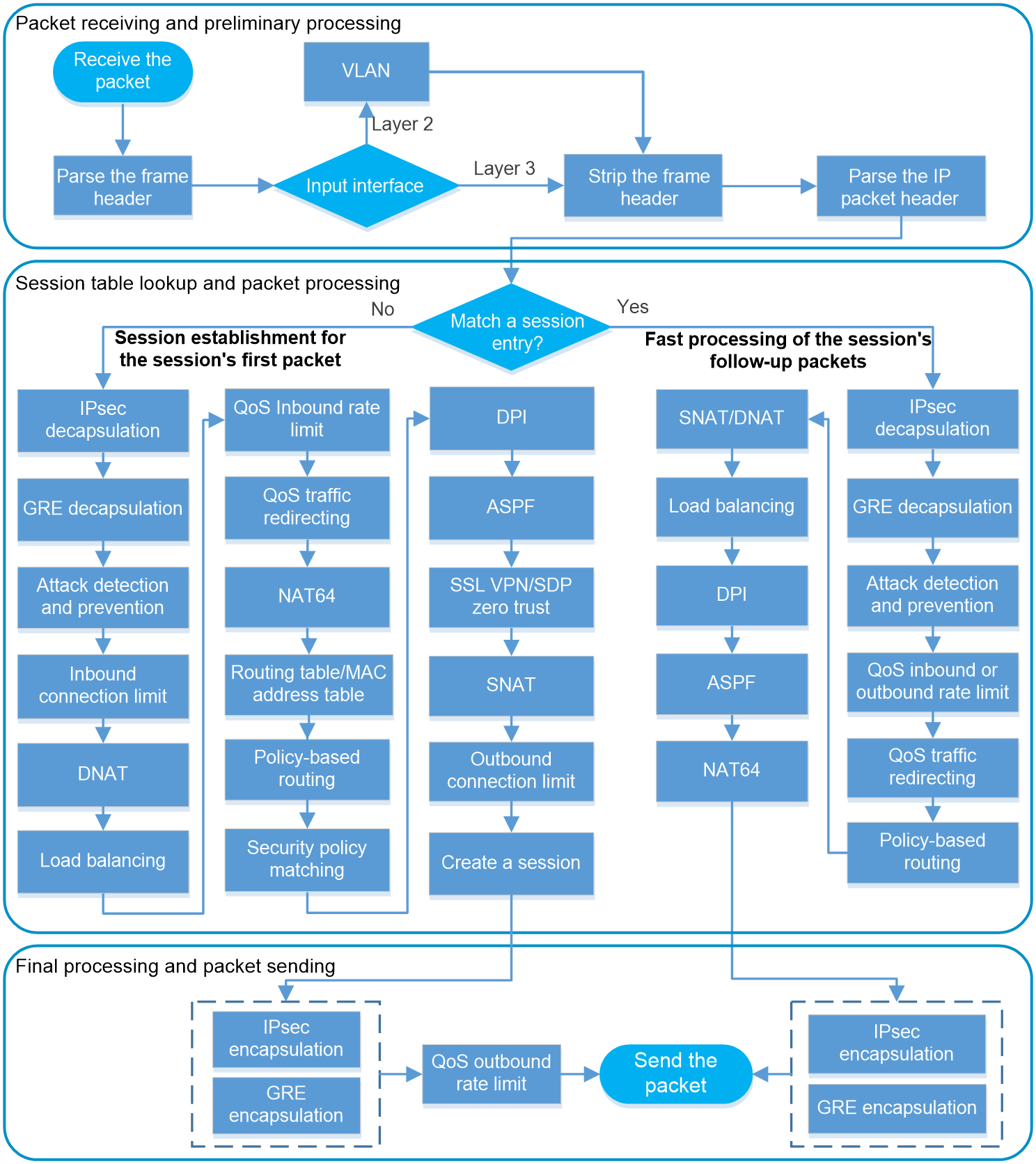
As shown in Figure 1, this document introduces the receiving, processing, and sending process of packets to help you better understand the configuration logic and methods of service modules on the device.
Figure 1 Packet forwarding process
|
|
NOTE: Support for the service modules varies by device model. Figure 1 is used for illustration only. |
A device processes traffic by detecting, identifying, forwarding, dropping, or modifying received packets. The packet processing actions are affected by packet types and configured processing policies.
Different service modules of the device process specific types of packets as configured. A packet might not be processed by all service modules in Figure 1. In general, the forwarding process of packets is as follows:
1. Packet receiving and preliminary processing.
2. Session table lookup and packet (first packet and follow-up packets) processing.
3. Final processing and packet sending.
Packet receiving and preliminary processing
In this phase, the device parses the frame or packet header of the incoming packet, and performs basic security detection on the header.
· Incoming packet received by a Layer 3 interface—The device looks up the routing table according to the destination address of the packet to determine the output interface.
· Incoming packet received by a Layer 2 interface—The device determines whether the frame of the packet is to be forwarded within a VLAN or between VLANs.
¡ For communication within a VLAN, the device looks up the MAC address table according to the destination address of the frame to determine the output interface.
¡ For communication between VLANs, the device obtains the VLAN ID of the VLAN to which the frame belongs and finds the corresponding subinterface or VLAN interface. Subinterfaces or VLAN interfaces are virtual Layer 3 interfaces for communications between VLANs. The packet can be forwarded according to its destination address through the routing table.
In both cases, the device extracts the information from the header, and then strips the header for further processing.
Table 1 shows the main service modules involved in packet processing in this phase.
Table 1 Main service modules involved in packet processing
|
Module |
Description |
|
VLAN |
The Virtual Local Area Network (VLAN) technology divides a physical LAN into multiple logical LANs. Hosts in the same VLAN can communicate with one another at Layer 2, but they are isolated from hosts in other VLANs at Layer 2, thus securing the LAN. |
Session table lookup and packet processing
This phase is at the core of packet processing, mainly including session establishment and session update. The device processes the packets according to whether the packet matches a session entry:
· Session establishment for the session's first packet—If the packet does not match a session entry, the ASPF module of the device inspects whether a session entry can be created for the packet. The device performs a series of checks and processing before session establishment.
· Fast processing of the session's follow-up packets—If the packet matches a session entry, the device does not create a new session. If the information of the session entry changes, the device updates the session entry, thus improving the efficiency of packet processing and forwarding.
Table 2 shows the main service modules involved in packet processing in this phase.
Table 2 Main service modules involved in packet processing
|
Module |
Description |
|
IPsec |
IP Security (IPsec) is defined by the IETF to provide interoperable, high-quality, cryptography-based security for IP communications. |
|
Attack detection and prevention |
Attack detection and prevention enables a device to detect attacks by inspecting arriving packets, and to take preventive actions to protect a private network. |
|
Connection limit |
The connection limit feature enables the device to monitor and limit the number of established connections, so as to protect internal network resources (hosts or servers) and reasonably allocate system resources. |
|
NAT |
Network Address Translation (NAT) translates an IP address in the IP packet header to another IP address. |
|
Load balancing |
Load balancing (LB) is a cluster technology that distributes network services and traffic among multiple network devices (such as servers and firewalls) or links. LB includes the following types: Server load balancing, outbound link load balancing, inbound link load balancing, transparent DNS proxy, and IAM trusted access control. |
|
QoS rate limit |
QoS rate limit can control the traffic rate. Rate limit controls the total rate of all packets on an interface. It is easier to use than traffic policing and Generic Traffic Shaping (GTS) in controlling the total traffic rate. |
|
QoS traffic redirecting |
QoS traffic redirecting redirects packets matching the specified match criteria to a location for processing. |
|
Policy-based routing |
Policy-based routing (PBR) uses user-defined policies to route packets. A policy can specify parameters for packets that match specific criteria such as ACLs or that have specific lengths. The parameters include the next hop, output interface, SRv6 TE policy, default next hop, default output interface, and default SRv6 TE policy. |
|
Security policy |
A security policy defines a set of rules for forwarding control. It matches packets against the rules and takes the action stated in the rules on the matched packets. |
|
DPI |
Deep packet inspection (DPI) inspects application layer payloads to protect the network against application layer malicious activities. |
|
ASPF |
ASPF can work with a packet-filter firewall to provide the network with a more comprehensive security policy that better meets the actual needs. |
|
SSL VPN |
SSL VPN provides a secure connection through an SSL VPN gateway for users from anywhere on the Internet to access protected resources behind the gateway. |
|
SDP zero trust |
SDP zero trust allows the device to act as an SDP gateway to cooperate with an SDP controller to authenticate and authorize users that access a specific application or API. This can centrally control user identities and access permissions to avoid illegal user access. |
Final processing and packet sending
In this phase, the device performs final processing before sending the packets, such as decapsulation or encapsulation for packets passing through a VPN tunnel and QoS outbound rate limit. The device processes the packets passing the VPN tunnel as follows:
· Upon receipt of a VPN encapsulated packet, the device decapsulates the packet to get the original data before sending the packet to the IP module for further forwarding.
· After receiving an IP packet, the device performs VPN encapsulation before forwarding it to the IP module for processing.
DPI mechanism
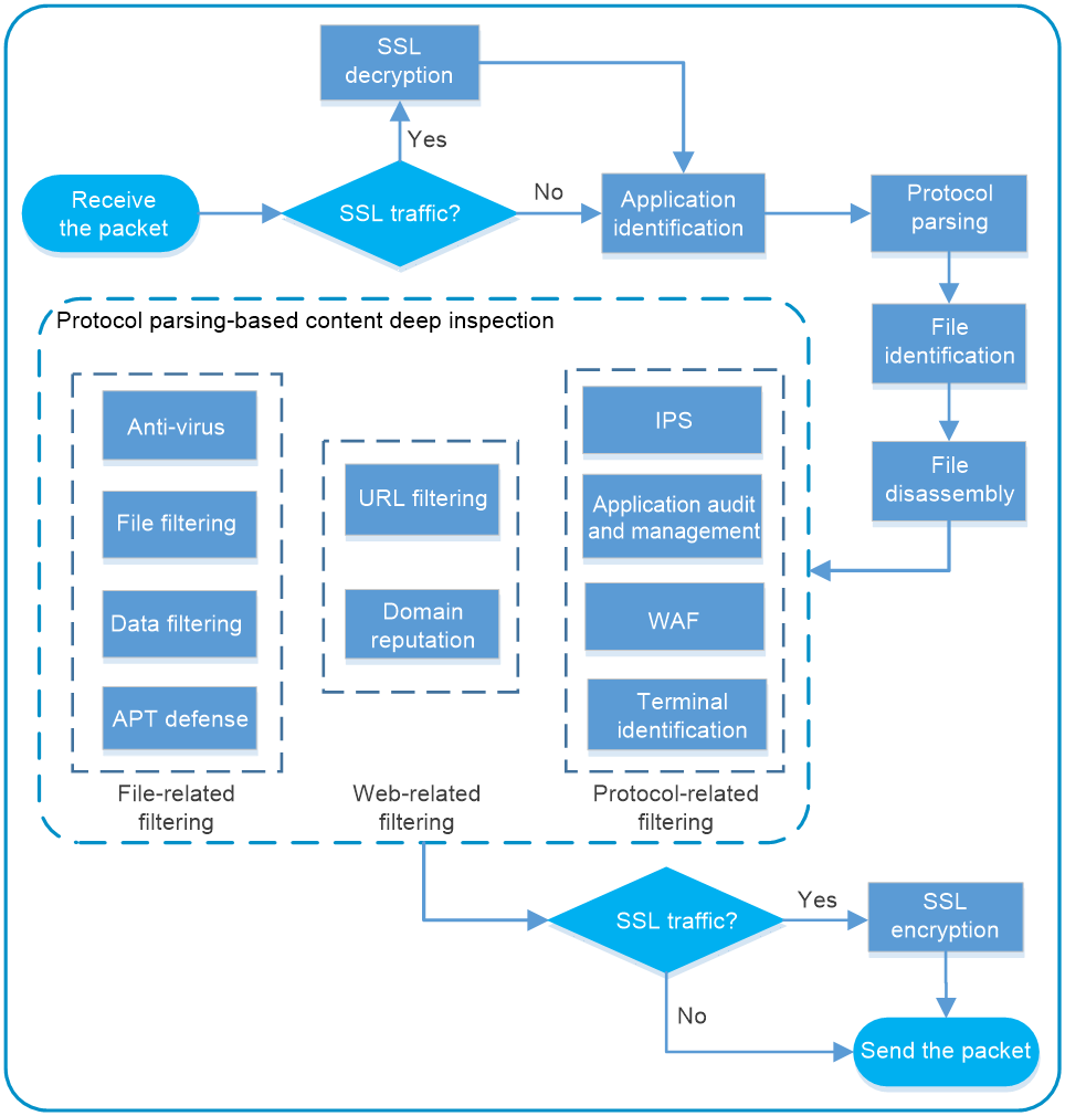
If DPI is configured in a security policy, the device performs deep packet inspection of matching traffic. Figure 2 illustrates how security policy-based DPI works.
Figure 2 Security policy-based DPI mechanism
|
|
NOTE: Support for the service modules varies by device model. Figure 2 is used for illustration only. Other supported service modules include DPI engine, data analysis center, proxy policy, IP reputation, DLP, content moderation, network asset scan, DGA detection, intelligent service platform, bandwidth management, and NetShare control. |
The device uses a high-performance DPI engine to process packets. The DPI engine works as follows:
1. If the traffic is SSL traffic, the device decrypts the packet before inspection.
2. The DPI engine identifies the protocols and applications from the packet.
The identified applications can be further processed according to the matching security policies.
3. The DPI engine performs deep protocol parsing for the packet, such as protocol parsing, uncompressing, and normalizing.
In this step, the DPI engine parses the fields and content used for deep inspection, greatly improving the inspection speed.
4. The DPI engine identifies the types of the files transmitted through the protocols.
5. The DPI engine performs different levels of disassembly on the files, such as file decompression and file unshelling.
6. The DPI engine submits the packet to matching DPI service modules for integrated deep inspection, such as anti-virus, URL filtering, and domain reputation.
Different DPI service modules process the packet in no strict order. Figure 2 illustrates the involved service modules.
7. For SSL traffic, the device re-encrypt the packet as an SSL encrypted packet before further forwarding.
Table 3 shows the main service modules involved in packet processing in this phase.
Table 3 Main service modules involved in packet processing
|
DPI service module |
Function |
|
IPS |
Intrusion prevention system (IPS) is a security feature that enables devices to monitor network traffic for malicious activity and to proactively take preventive actions. |
|
URL filtering |
URL filtering controls access to the Web resources by filtering the URLs that the users visit. |
|
Data filtering |
Data filtering filters packets based on application layer information. You can use data filtering to effectively prevent leakage of internal information, distribution of illegal information, and unauthorized access to the Internet. |
|
File filtering |
The file filtering feature filters files based on file extensions. |
|
Anti-virus |
Anti-virus inspects and handles viruses in files to protect the internal network. |
|
Application audit and management |
Based on APR, application audit and management audits and records Internet access behaviors of users by identifying behaviors (for example, login and message sending in IM applications) and behavior objects (for example, account information for IM login). |
|
WAF |
The Web application firewall (WAF) feature protects the internal clients and Web servers by preventing Web application layer attacks. |
|
APT defense |
An advanced persistent threat (APT) is a prolonged and targeted cyberattack. One of the most effective methods to defend against APT attacks is the sandbox technology. The sandbox technology creates an isolated threat inspection environment to analyze traffic that is delivered to it. |
|
Terminal identification |
Identifying terminals is fundamental to establish secure Internet of Things (IoT) connections. When the terminal traffic passes through a device, the device analyzes and extracts the terminal information. |
|
Domain reputation |
The domain reputation feature uses domain names on the domain reputation signature library to filter network traffic. The device enabled with the domain reputation feature can control network access behaviors of the users. |
|
IP reputation |
The IP reputation feature uses IP addresses on the IP reputation list to filter network traffic. |
|
DPI engine |
DPI engine is an inspection module shared by DPI service modules. DPI engine uses inspection rules to identify the application layer information, including the application layer protocol and behavior. |
|
Data analysis center |
The data analysis center collects and analyzes log data for services and provides the analysis results in various forms of reports through the Web interface. |
|
Proxy policy |
The proxy policy enables the device to proxy specific connections between clients and servers and implement deep packet inspection and audit on the traffic for high security. |
|
DLP |
Data loss prevention (DLP) is used to detect sensitive information in files transferred by the device and notify users of sensitive information leakage. |
|
Content moderation |
Content moderation is a technology that intelligently inspects and recognizes sensitive contents in files transported over networks. |
|
Network asset scan |
Network asset scan is a technology used to identify and audit network assets such as hosts, servers, and devices in a network. |
|
DGA detection |
Based on deep learning algorithms, Domain Generation Algorithm (DGA) detection can effectively detect and log the DGA domain names that may be contained in DNS request packets, and block the communication traffic between the intranet botnet hosts and the Command and Control Servers (C&C servers, servers that issue attack instructions to malware). You can view the generated reports to accurately locate the intranet botnet hosts. |
|
Intelligent service platform |
The intelligent service platform is a comprehensive service deployment platform designed for security applications. |
|
Bandwidth management |
Bandwidth management provides fine-grained control over traffic that flows through the device by using the following information: · SSIDs. · User profiles. · Source and destination security zones. · Source and destination IP addresses. · Services. · Users/user groups. · Applications. · DSCP priorities. |
|
NetShare control |
NetShare control uses the NetShare control policy to identify and control network sharing behaviors. The network sharing behavior is the behavior of multiple terminals using the same IP address for network access through NAT or proxy. |
Guidelines for configuring security policies and routes in NAT scenarios
In packet processing, some modules may modify specific fields of the packet. For example, the NAT module translates the source or destination IP address of the packet for NAT service. However, the security policy and routing modules match packets against the configured rules based on the actual IP addresses. You must follow the corresponding guidelines for configuring security policies and routes in different NAT scenarios.
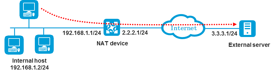
SNAT scenario
As shown in Figure 3, configure the security policy and routes to allow the internal host at 192.168.1.2 to access the external server at 3.3.3.1.
Configure the security policy as follows:
· Set the source IP address to the IP address of the internal host before SNAT (192.168.1.2).
· Set the destination IP address to the IP address of the server in the public network (3.3.3.1).
Configure the routes as follows:
· Inbound route:
¡ Make sure packets destined for 3.3.3.1 can be forwarded to the NAT device.
¡ Make sure the NAT device and the external server can reach each other.
· Outbound route:
¡ Make sure packets destined for the IP address of the internal host after SNAT (for example, 2.2.2.2) can be forwarded to the NAT device.
¡ Make sure the NAT device and the internal host can reach each other.
DNAT scenario
As shown in Figure 4, configure the security policy and routes to allow the external host at 3.3.3.1 to access the internal server at 192.168.1.2.
Configure the security policy as follows:
· Set the source IP address to the IP address of the external host in the public network (3.3.3.1).
· Set the destination IP address to the IP address of the internal server after DNAT (192.168.1.2).
Configure the routes as follows:
· Inbound route:
¡ Make sure packets destined for the public address of the internal server can be forwarded to the NAT device.
¡ Make sure the NAT device and the internal server can reach each other.
· Outbound route:
¡ Make sure packets destined for 3.3.3.1 can be forwarded to the NAT device.
¡ Make sure the NAT device and the external host can reach each other.

SNAT + DNAT scenario
As shown in Figure 5, in the scenario with the combination of SNAT and DNAT, configure the security policy and routes to allow the external host at 3.3.3.1 to access the internal server at 192.168.1.2.
Configure the security policy as follows:
· Set the source IP address to the IP address of the external host in the public network (3.3.3.1).
· Set the destination IP address to the IP address of the internal server after DNAT (192.168.1.2).
Configure the routes as follows:
· Inbound route:
¡ Make sure packets destined for the public address of the internal server can be forwarded to the NAT device.
¡ Make sure the NAT device and the internal server can reach each other.
· Outbound route:
¡ Make sure packets destined for the IP address of the internal server after SNAT (for example, 192.168.1.10) can be forwarded to the NAT device.
¡ Make sure the NAT device and the external host can reach each other.

Guidelines for configuring security policies in IPsec scenario
In IPsec scenario, the IPsec security gateways perform IKE negotiations to establish an IPsec tunnel for protecting matching packets. You must configure security policy rules to permit both the packets between the gateways and the packets for IKE negotiations and IPsec encapsulation.
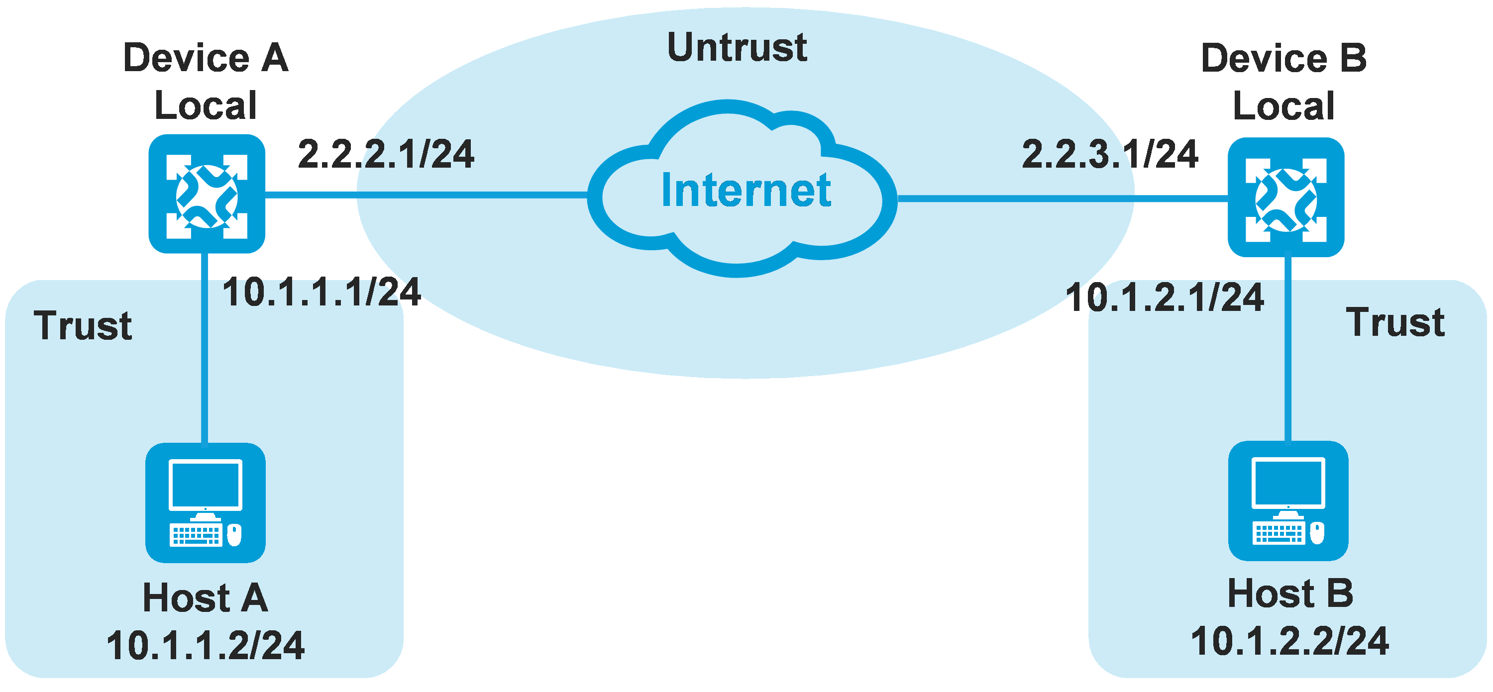
As shown in Figure 6, establish an IPsec tunnel between Device A and Device B to protect data flows between subnet 10.1.1.0/24 and subnet 10.1.2.0/24. Configure the security policy rules as follows:
· Configure rules to permit the packets for IKE negotiations and IPsec encapsulation:
¡ Configure a rule from security zone Local to Untrust to permit Device A to send IKE negotiation and IPsec encapsulation packets to Device B.
- Set the source IP address to the public address of Device A (2.2.2.1).
- Set the destination IP address to the public address of Device B (2.2.3.1).
¡ Configure a rule from security zone Untrust to Local to permit Device A to receive IKE negotiation and IPsec encapsulation packets sent from Device B.
- Set the source IP address to the public address of Device B (2.2.3.1).
- Set the destination IP address to the public address of Device A (2.2.2.1).
· Configure rules to permit the traffic between Host A and Host B.
¡ Configure a rule from security zone Trust to Untrust to permit the packets from Host A to Host B.
- Set the source IP address to the IP address of Host A (10.1.1.2).
- Set the destination IP address to the IP address of Host B (10.1.2.2).
¡ Configure a rule from security zone Untrust to Trust to permit the packets from Host B to Host A.
- Set the source IP address to the IP address of Host B (10.1.2.2).
- Set the destination IP address to the IP address of Host A (10.1.1.2).