- Table of Contents
- Related Documents
-
| Title | Size | Download |
|---|---|---|
| 03-Cisco ISE Authentication Server Integration Guide | 7.66 MB |
|
|
|
H3C Switches and Cisco ISE Authentication Server Integration Guide |
|
|
|
|
|
|
Copyright © 2023 New H3C Technologies Co., Ltd. All rights reserved.
No part of this manual may be reproduced or transmitted in any form or by any means without prior written consent of New H3C Technologies Co., Ltd.
Except for the trademarks of New H3C Technologies Co., Ltd., any trademarks that may be mentioned in this document are the property of their respective owners.
The information in this document is subject to change without notice.
H3C switches and Cisco ISE server compatibility in authentication methods
Examples: Configuring 802.1X authentication
Hardware and software versions used
Example: Configuring 802.1X CHAP authentication
Example: Configuring 802.1X PAP authentication
Example: Configuring 802.1X EAP-MD5 authentication
Example: Configuring 802.1X PEAP or EAP-TTLS authentication
Example: Configuring 802.1X EAP-TLS authentication
Example: Configuring 802.1X EAP-FAST authentication
Example: Configuring MAC authentication
Hardware and software versions used
Example: Configuring portal authentication
Hardware and software versions used
Example: Configuring 802.1X or MAC authentication with VLAN assignment
Hardware and software versions used
Configuring the Cisco ISE server
Examples: Configuring 802.1X, MAC, or portal authentication with static ACL assignment
Hardware and software versions used
Examples: Configuring 802.1X, MAC, or portal authentication with dynamic ACL assignment
Hardware and software versions used
Examples: Configuring 802.1X or MAC authentication with CAR setting assignment
Hardware and software versions used
Example: Configuring URL redirection
Hardware and software versions used
Hardware and software versions used
Example: Configuring HWTACACS authentication for SSH login
Hardware and software versions used
Verifying role and command authorization
Example: Configuring LDAP account collaboration with authentication
Hardware and software versions used
Examples: Configuring endpoint profiling
Hardware and software versions used
Example: Configuring endpoint profiling
Configuring the Windows client
Installing LLDP-related modules
Examples: Configuring endpoint security posture assessment
Hardware and software versions used
Example: Configuring endpoint security posture assessment
Installing AnyConnect for client provisioning
Introduction
This document provides examples for integrating H3C switches with a Cisco ISE server for user access authentication. This document provides examples for the following authentication and authorization features:
· 802.1X authentication.
· MAC authentication.
· Portal authentication.
· Authorization VLAN assignment.
· Authorization static ACL assignment.
· Authorization dynamic ACL assignment.
· Authorization CAR assignment.
· URL redirection.
· DAE.
· SSH login with HWTACACS authentication
· Authentication with LDAP server
· Endpoint profiling
· Endpoint security posture assessment
Support for the authentication and authorization features depends on the device model. For more information, see the security configuration guide for your switch.
H3C switches and Cisco ISE server compatibility in authentication methods
|
H3C switches |
Cisco ISE |
Compatibility |
|
802.1X CHAP authentication |
CHAP authentication |
Yes |
|
802.1X PAP authentication |
PAP authentication |
Yes |
|
802.1X EAP authentication |
EAP-MD5 authentication |
Yes |
|
802.1X EAP authentication |
EAP-PEAP/TTLS authentication |
Yes |
|
802.1X EAP authentication |
EAP-TLS authentication |
Yes |
|
802.1X EAP authentication |
EAP-FAST authentication |
Yes |
|
MAC authentication |
MAC authentication |
Yes |
|
Portal authentication |
CWA authentication |
Yes |
|
Authorization VLAN |
Authorization VLAN |
Yes |
|
Authorization ACL |
Authorization static ACL |
Yes |
|
Authorization ACL |
Authorization dynamic ACL |
Yes |
|
Authorization CAR |
Authorization CAR |
Yes |
|
Authorization URL redirection |
URL redirection |
Yes |
|
DAE |
Reauthentication |
Yes |
|
SSH login with HWTACACS authentication |
HWTACACS authentication |
Yes |
|
Authentication with LDAP server |
LDAP authentication |
Yes |
|
N/A |
Endpoint profiling |
Yes |
|
N/A |
Endpoint security posture assessment |
Yes |
Prerequisites
The following information applies to H3C switches. Procedures and information in the examples might be slightly different depending on the software or hardware version of the switch and the software version of the Cisco ISE server.
The configuration examples were created and verified in a lab environment, and all the devices were started with the factory default configuration. When you are working on a live network, make sure you understand the potential impact of every configuration item on your network.
Examples: Configuring 802.1X authentication
Network configuration
As shown in Figure 1, configure the switch to work in conjunction with the Cisco ISE server to perform 802.1X authentication for the client. The client must pass 802.1X authentication to access network resources.
Configure the switch as follows:
· Use the Cisco ISE server as the RADIUS server to perform 802.1X authentication for the client.
· Use PAP, CHAP, EAP-MD5, EAP-TLS, EAP-PEAP, or EAP-TTLS authentication method for 802.1X authentication.

Hardware and software versions used
This configuration example was created and verified on the following hardware and software versions:
|
Hardware |
Software version |
|
Switch (S5560X) |
R6618P27 |
|
Authentication server |
Cisco ISE V2.4.0.357 patch 8 |
|
Client operating system |
Windows 10 21H2 |
|
Authentication client |
iNode PC 7.3 (E513) |
|
Authentication client |
Cisco anyconnect 4.8.03052 |
Example: Configuring 802.1X CHAP authentication
Prerequisites
This example provides only the configuration for authentication. Make sure that the client, switch, and server have network connectivity to communicate with one another.
Configuring the switch
# Create VLAN 2 and VLAN 3, and assign IP addresses to the VLAN interfaces.
<Switch> system-view
[Switch] vlan 2
[Switch-vlan2] quit
[Switch] interface Vlan-interface 2
[Switch-Vlan-interface2] ip address 2.2.2.29 255.255.255.0
[Switch-Vlan-interface2] quit
[Switch] vlan 3
[Switch-vlan3] quit
[Switch] interface Vlan-interface 3
[Switch-Vlan-interface3] ip address 3.3.3.29 255.255.255.0
[Switch-Vlan-interface3] quit
# Assign GigabitEthernet 1/0/2 to VLAN 3.
[Switch] interface GigabitEthernet 1/0/2
[Switch-GigabitEthernet1/0/2] port switchcess vlan 3
[Switch-GigabitEthernet1/0/2] quit
# Enable 802.1X globally.
[Switch] dot1x
# Specify the 802.1X authentication method as CHAP.
[Switch] dot1x authentication-method CHAP
# Create RADIUS scheme ise.
<Switch> system-view
[Switch] radius scheme ise
# Specify the RADIUS server (Cisco ISE) at 3.3.3.24 for user authentication and accounting, set the shared key to expert in plaintext form, and use the original format for usernames sent to the RADIUS server. Make sure the shared key is the same as the shared secret configured on the ISE server.
[Switch-radius-ise] primary authentication 3.3.3.24 key simple expert
[Switch-radius-ise] primary accounting 3.3.3.24 key simple expert
[Switch-radius-ise] user-name-format keep-original
[Switch-radius-ise] quit
# Create ISP domain test.com and apply the RADIUS scheme to the ISP domain for authentication, authorization, and accounting.
[Switch] domain test.com
[Switch-isp-test.com] authentication default radius-scheme ise
[Switch-isp-test.com] authorization default radius-scheme ise
[Switch-isp-test.com] accounting default radius-scheme ise
[Switch-isp-test.com] quit
# Add port GigabitEthernet 1/0/3 to VLAN 2.
[Switch]interface GigabitEthernet 1/0/3
[Switch-GigabitEthernet1/0/3] port switchcess vlan 2
# Enable 802.1X on GigabitEthernet 1/0/3 and specify ISP domain test.com as the mandatory domain.
[Switch-GigabitEthernet1/0/3] dot1x
[Switch-GigabitEthernet1/0/3] dot1x mandatory-domain test.com
Configuring the ISE server
1. Log in to ISE:
# Enter the management IP address of ISE.
# Enter the username and password and then click Login.
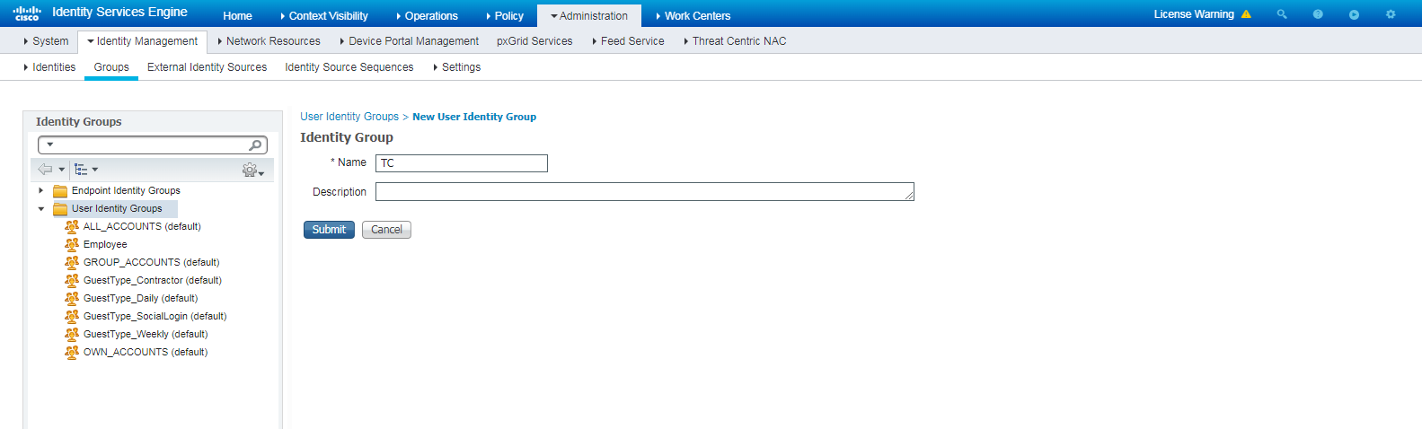
2. Create a user identity group and a user account:
# To create a user identity group, navigate to the Administration > Identity Management > Groups page. In the left pane, right-click User Identity Groups and then click Add.
Figure 2 Creating a user identity group
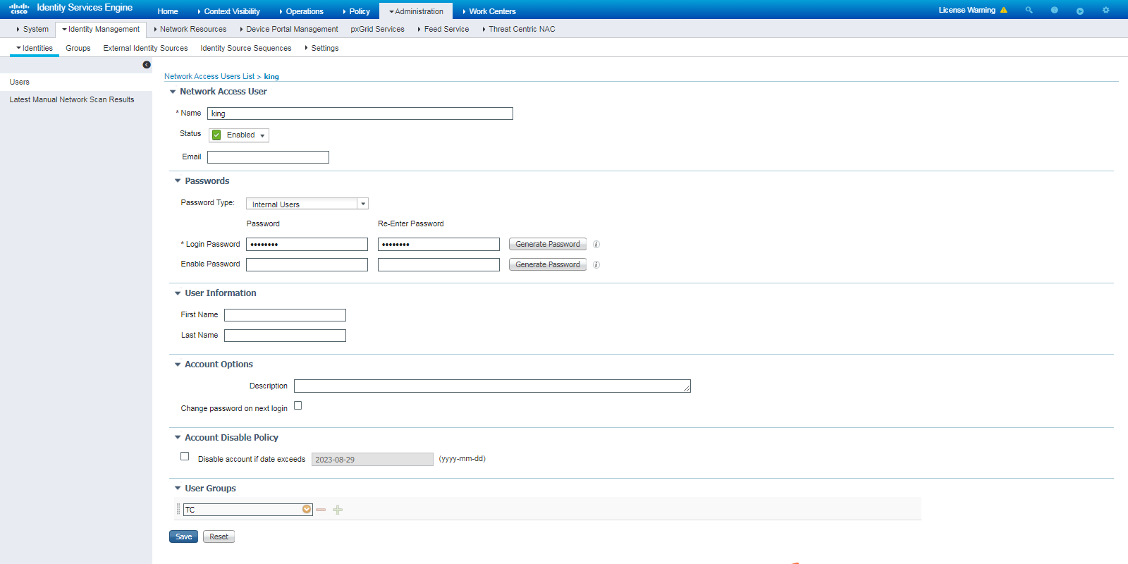
# To create a user account, navigate to the Administration > Identity Management > Identities page. In the left pane, right-click Users and then click Add.
Figure 3 Creating a user account
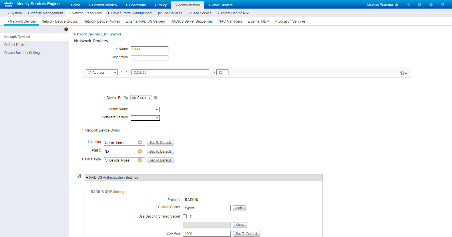
3. Add the H3C switch to ISE:
# Navigate to the Administration > Network Resources > Network Devices page. In the left pane, right-click Network Devices and then click Add to add a new network device.
# Configure the network device name as SW001, IP address as 3.3.3.29 (the same as NAS-IP configured on the switch), and shared secret as expert (the same as the RADIUS shared key configured on the switch).
Figure 4 Adding the switch to ISE
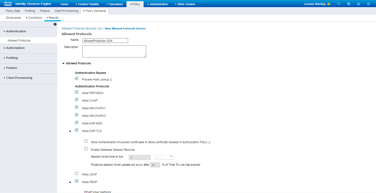
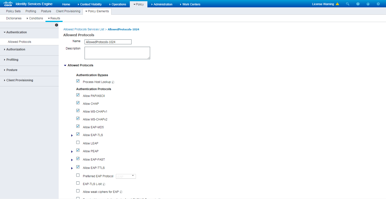
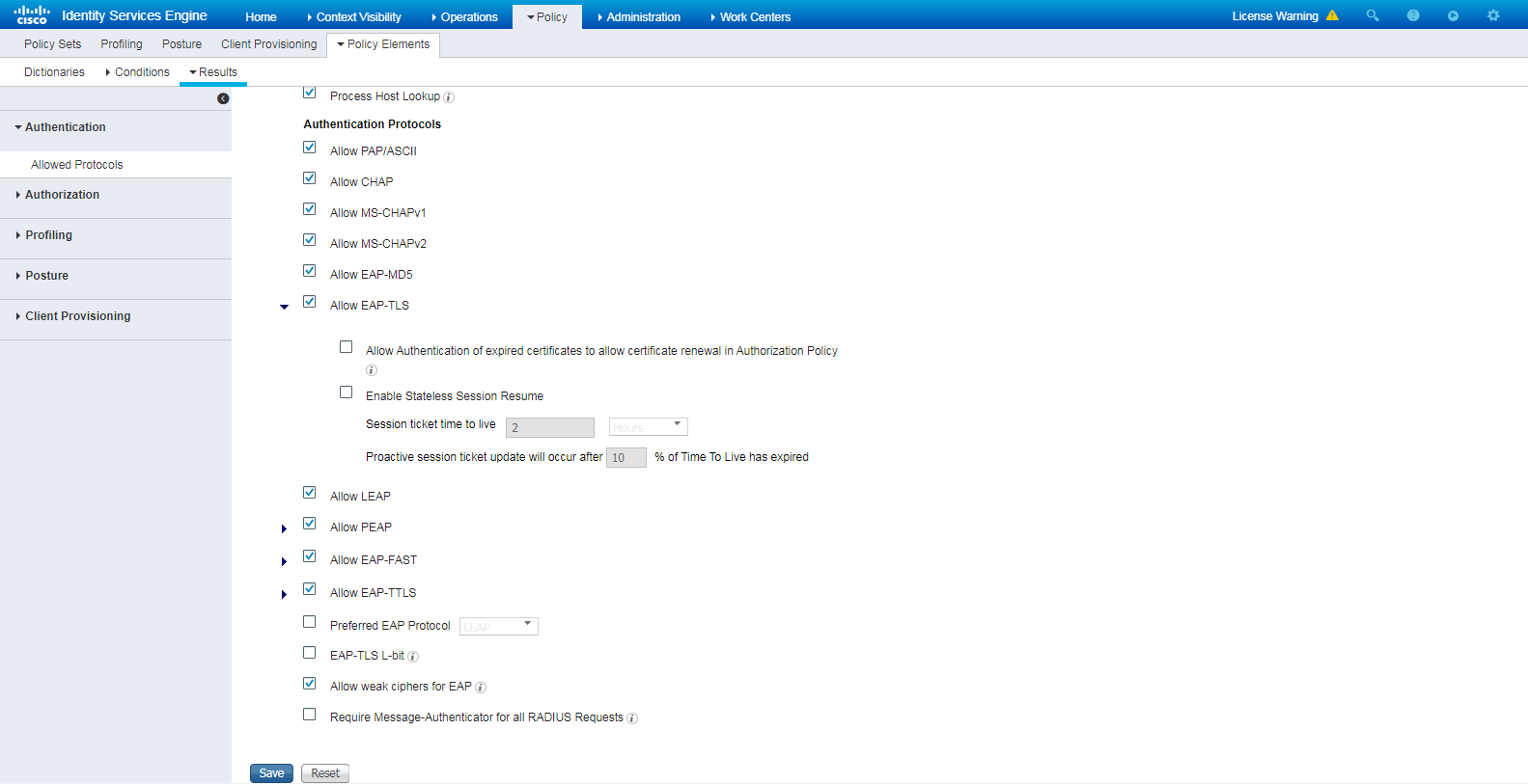
4. Configure authentication protocols:
# Navigate to Policy > Policy Elements > Results > Authentication > Allowed Protocols. Right-click Allowed Protocols and then click Add to add a new allowed protocols service.
# Configure the service name as AllowedProtocols-1024 and make sure the Allow CHAP option in the Authentication Protocols area is selected.
Figure 5 Adding an allowed protocols service
5. Add authentication and authorization policy sets:
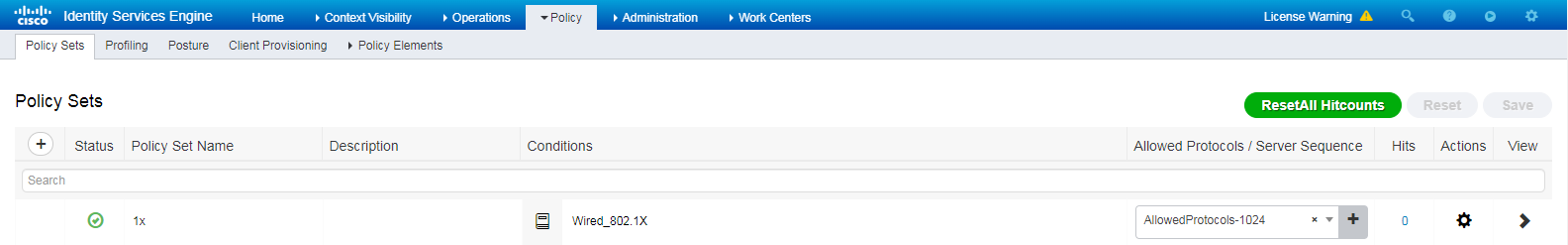
# Navigate to Policy > Policy Sets.
# Click the plus sign (+) to add a policy set named 1x, select Wired_Dot1x for the Conditions column, and select Default Network Access for the Allowed Protocols/Server Sequence column.
Figure 6 Adding authentication and authorization policy set (1)
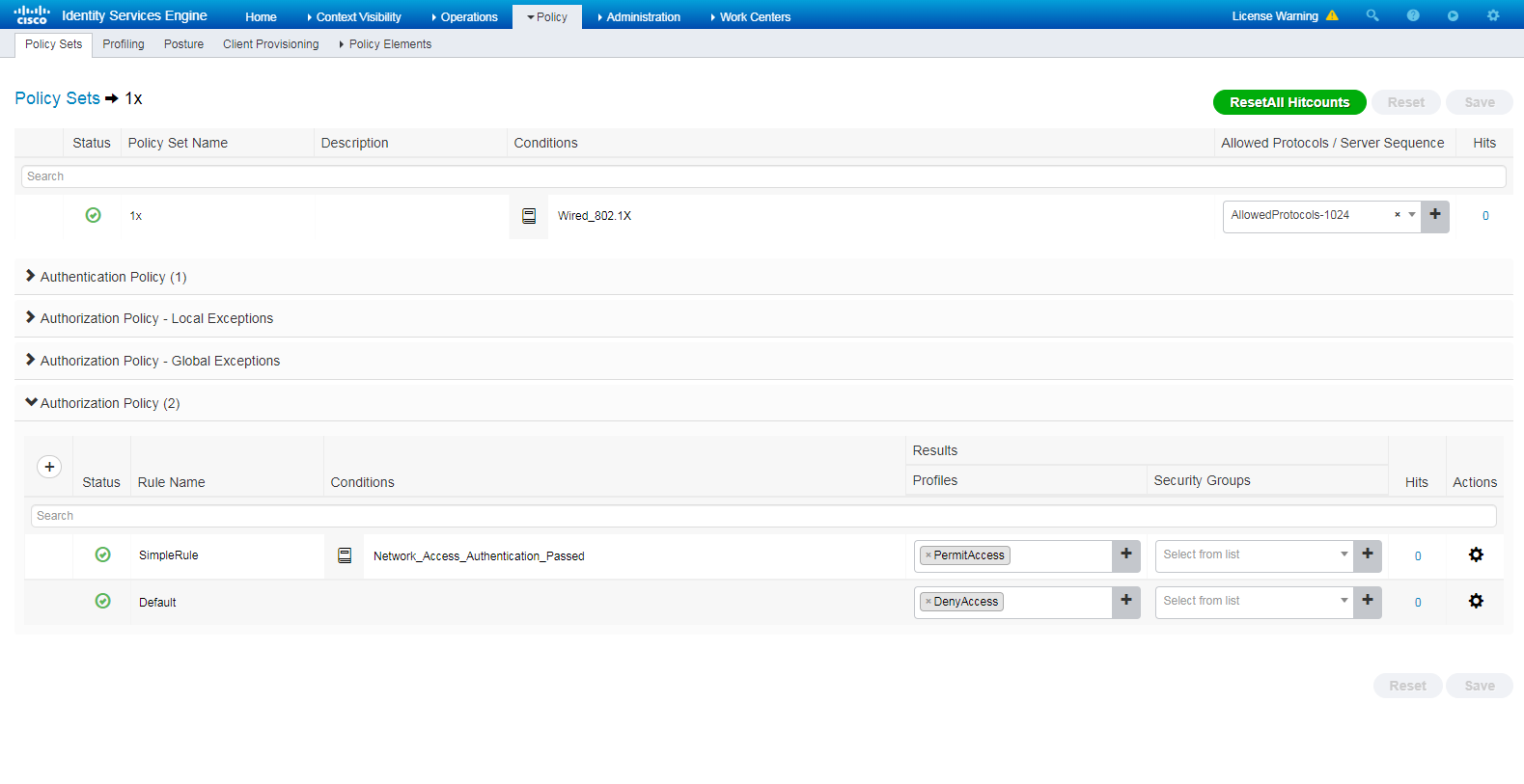
# Click the View icon for policy set 1x. In the Authorization Policy area, add an authorization policy named SimpleRule, and select PermitAccess in the Result Profiles column.
Figure 7 Adding authentication and authorization policy set (2)
Verifying the configuration
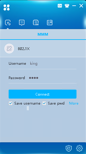
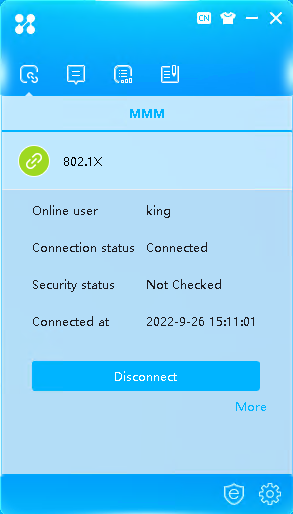
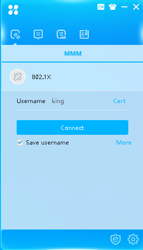
1. Use the iNode client to verify that you can pass 802.1X CHAP authentication to come online after you enter the username and password:
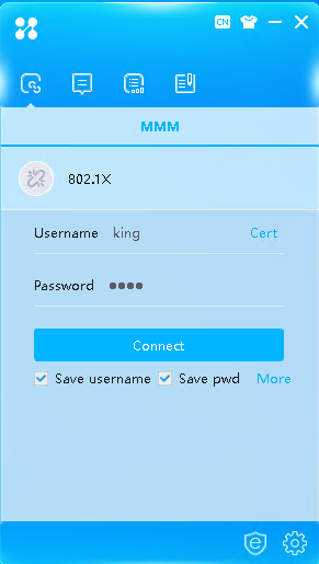
# Click More on the iNode client interface for 802.1X authentication.
Figure 8 iNode connection
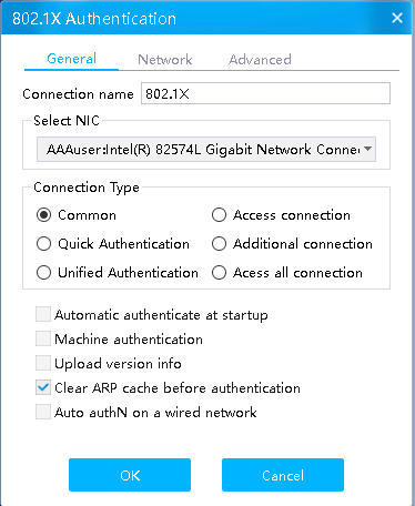
# As a best practice, unselect the Upload version info option and then click OK.
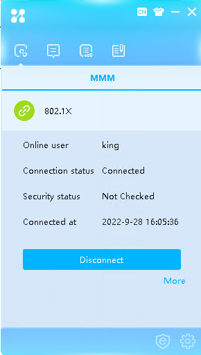
Figure 9 Successful 802.1X connection
# Enter the configured username and password and then click Connect. You can pass authentication and come online.
Figure 10 Successful 802.1X connection
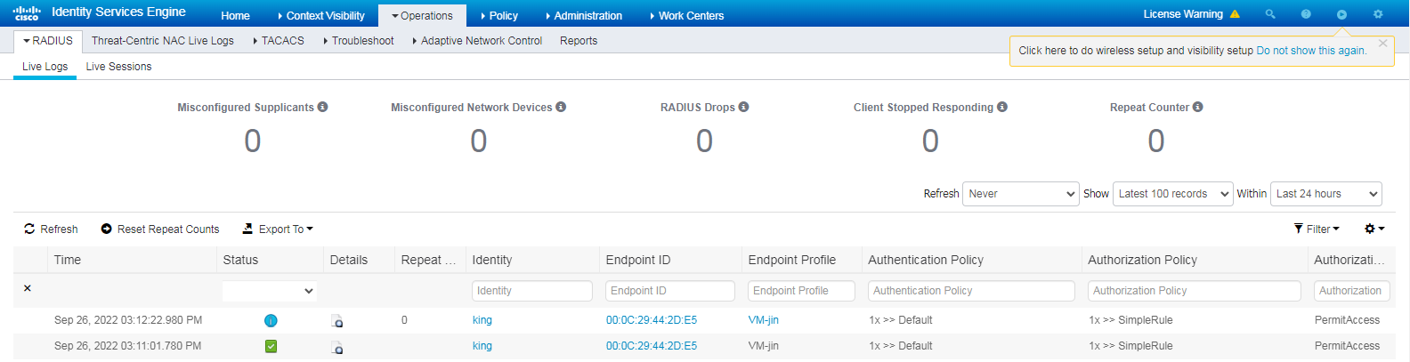
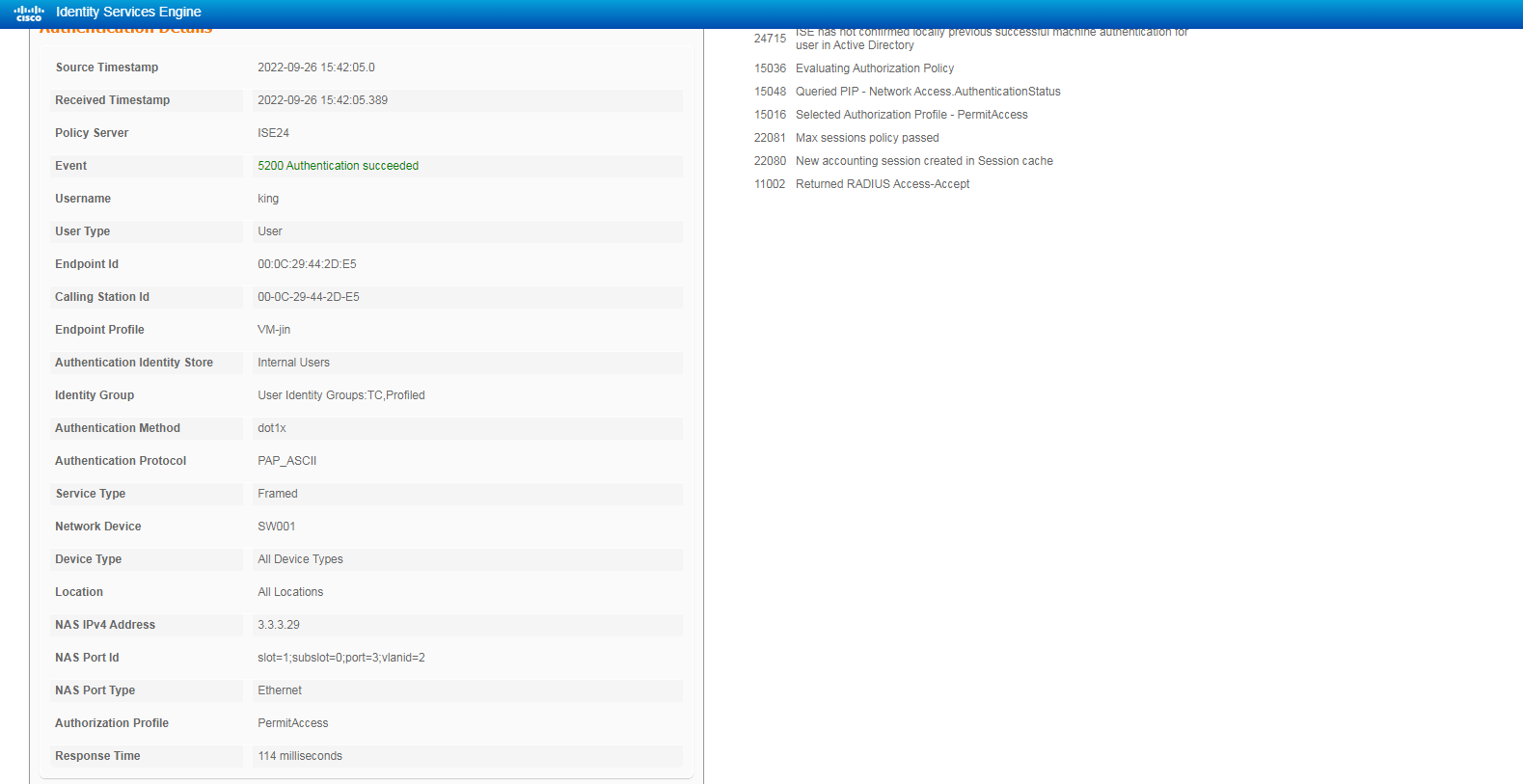
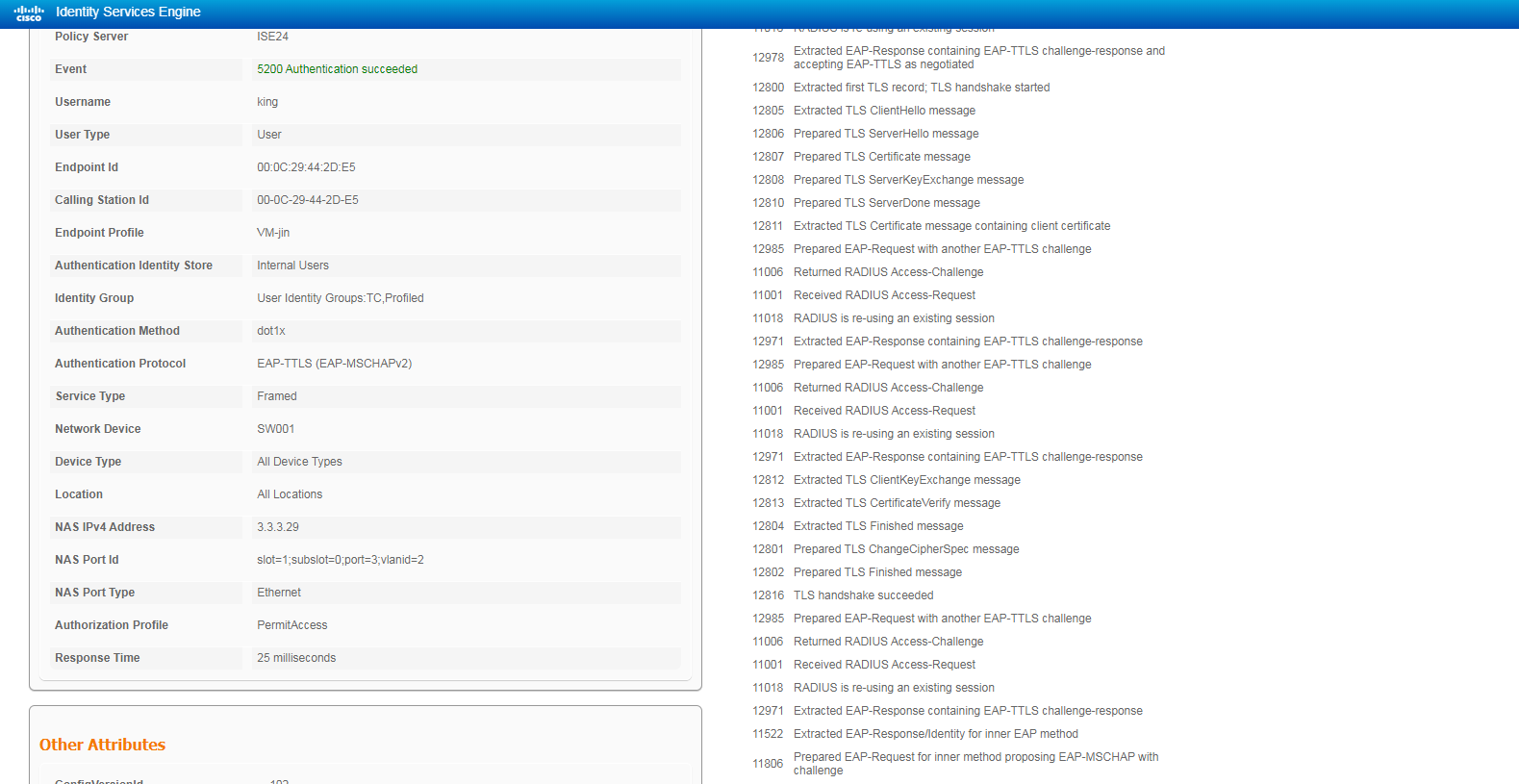
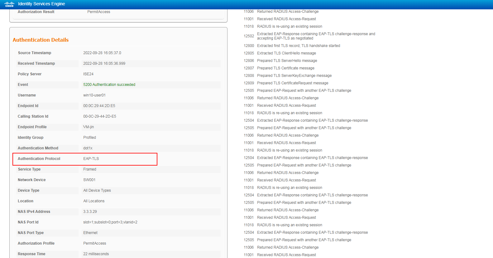
2. On the ISE server, view information about the online user.
Figure 11 Viewing live logs for online users
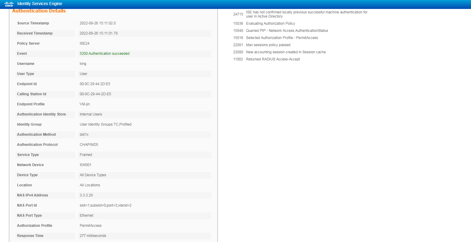
# Click the Details icon for a log to view the authentication details. You can see the authentication protocol. In this example, it is CHAP/MD5.
Figure 12 Viewing authentication details for a live log
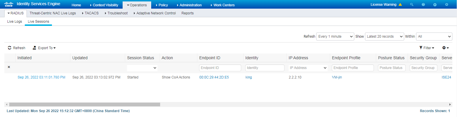
# Click the Live Sessions tab to view live sessions of online endpoints.
Figure 13 Viewing live sessions
3. On the switch, use the display dot1x connection command to display information about online 802.1X authentication users.
<Switch> display dot1x connection
Total connections: 1
Slot ID: 1
User MAC address: 000c-2944-2de5
Access interface: GigabitEthernet1/0/3
Username: king
User access state: Successful
Authentication domain: ise
IPv4 address: 2.2.2.10
IPv4 address source: IP Source Guard
EAP packet identifier: 2
Authentication method: CHAP
AAA authentication method: RADIUS
Initial VLAN: 2
Authorization untagged VLAN: N/A
Authorization tagged VLAN list: N/A
Authorization VSI: N/A
Authorization microsegment ID: N/A
Authorization ACL number/name: N/A
Authorization dynamic ACL name: N/A
Authorization user profile: N/A
Authorization CAR: N/A
Authorization URL: N/A
Authorization IPv6 URL: N/A
Authorization temporary redirect: Disabled
Start accounting: Successful
Real-time accounting-update failures: 0
Termination action: Default
Session timeout period: N/A
Online from: 2022/09/26 15:09:04
Online duration: 0h 7m 55s
The output shows that the user has passed 802.1X CHAP authentication and come online.
Configuration files
#
dot1x
dot1x authentication-method chap
#
vlan 1
#
vlan 2
description toClients
arp snooping enable
#
vlan 3
description toAAAserver
#
interface Vlan-interface1
#
interface Vlan-interface2
description toClients
ip address 2.2.2.29 255.255.255.0
#
interface Vlan-interface3
description toAAAservers
ip address 3.3.3.29 255.255.255.0
#
interface GigabitEthernet1/0/2
port link-mode bridge
port access vlan 3
#
interface GigabitEthernet1/0/3
port link-mode bridge
port access vlan 2
dot1x
#
radius scheme ise
primary authentication 3.3.3.24 key cipher $c$3$2oLOvHdRilTBlb6n1yh3/MoXN8z/RMbctQ==
primary accounting 3.3.3.24 key cipher $c$3$fAhWH/rHm9hCcPq2PBWQa54YG9xKuQ1P0w==
timer realtime-accounting 20 second
user-name-format keep-original
#
#
domain test.com
authentication default radius-scheme ise
authorization default radius-scheme ise
accounting default radius-scheme ise
#
Example: Configuring 802.1X PAP authentication
Configuring the switch
Configure the switch as described in "Configuring the switch," except that you must set the authentication method to PAP as follows:
[Switch] dot1x authentication-method PAP
Configuring the ISE server
Configure the ISE server as described in "Configuring the ISE server," except that you must select Allow PAP/ASCII for the Allowed Protocols service.
Figure 14 Selecting the Allow PAP/ASCII authentication protocol

Verifying the configuration
1. Use the iNode client to verify that you can pass 802.1X authentication to come online after you enter the username and password. (Details not shown.)
2. On the ISE server, view information about the online user.
Figure 15 Viewing user access information
3. On the switch, use the display dot1x connection command to display information about online 802.1X authentication users.
<Switch> display dot1x connection
Total connections: 1
Slot ID: 1
User MAC address: 000c-2944-2de5
Access interface: GigabitEthernet1/0/3
Username: king
User access state: Successful
Authentication domain: ise
IPv4 address: 2.2.2.10
IPv4 address source: IP Source Guard
EAP packet identifier: 2
Authentication method: PAP
AAA authentication method: RADIUS
Initial VLAN: 2
Authorization untagged VLAN: N/A
Authorization tagged VLAN list: N/A
Authorization VSI: N/A
Authorization microsegment ID: N/A
Authorization ACL number/name: N/A
Authorization dynamic ACL name: N/A
Authorization user profile: N/A
Authorization CAR: N/A
Authorization URL: N/A
Authorization IPv6 URL: N/A
Authorization temporary redirect: Disabled
Start accounting: Successful
Real-time accounting-update failures: 0
Termination action: Default
Session timeout period: N/A
Online from: 2022/09/26 15:40:08
Online duration: 0h 1m 16s
The output shows that the user has passed 802.1X PAP authentication and come online.
Configuration files
#
dot1x
dot1x authentication-method pap
#
vlan 1
#
vlan 2
description toClients
arp snooping enable
#
vlan 3
description toAAAserver
#
interface Vlan-interface1
#
interface Vlan-interface2
description toClients
ip address 2.2.2.29 255.255.255.0
#
interface Vlan-interface3
description toAAAservers
ip address 3.3.3.29 255.255.255.0
#
interface GigabitEthernet1/0/2
port link-mode bridge
port access vlan 3
#
interface GigabitEthernet1/0/3
port link-mode bridge
port access vlan 2
dot1x
#
radius scheme ise
primary authentication 3.3.3.24 key cipher $c$3$2oLOvHdRilTBlb6n1yh3/MoXN8z/RMbctQ==
primary accounting 3.3.3.24 key cipher $c$3$fAhWH/rHm9hCcPq2PBWQa54YG9xKuQ1P0w==
timer realtime-accounting 20 second
user-name-format keep-original
#
#
domain test.com
authentication default radius-scheme ise
authorization default radius-scheme ise
accounting default radius-scheme ise
#
Example: Configuring 802.1X EAP-MD5 authentication
Configuring the switch
Configure the switch as described in "Configuring the switch," except that you must set the authentication method to EAP as follows:
[Switch] dot1x authentication-method EAP
Configuring the ISE server
Configure the ISE server as described in "Configuring the ISE server," except that you must select Allow EAP-MD5 for the Allowed Protocols service.
Figure 16 Selecting the Allow EAP-MD5 authentication protocol
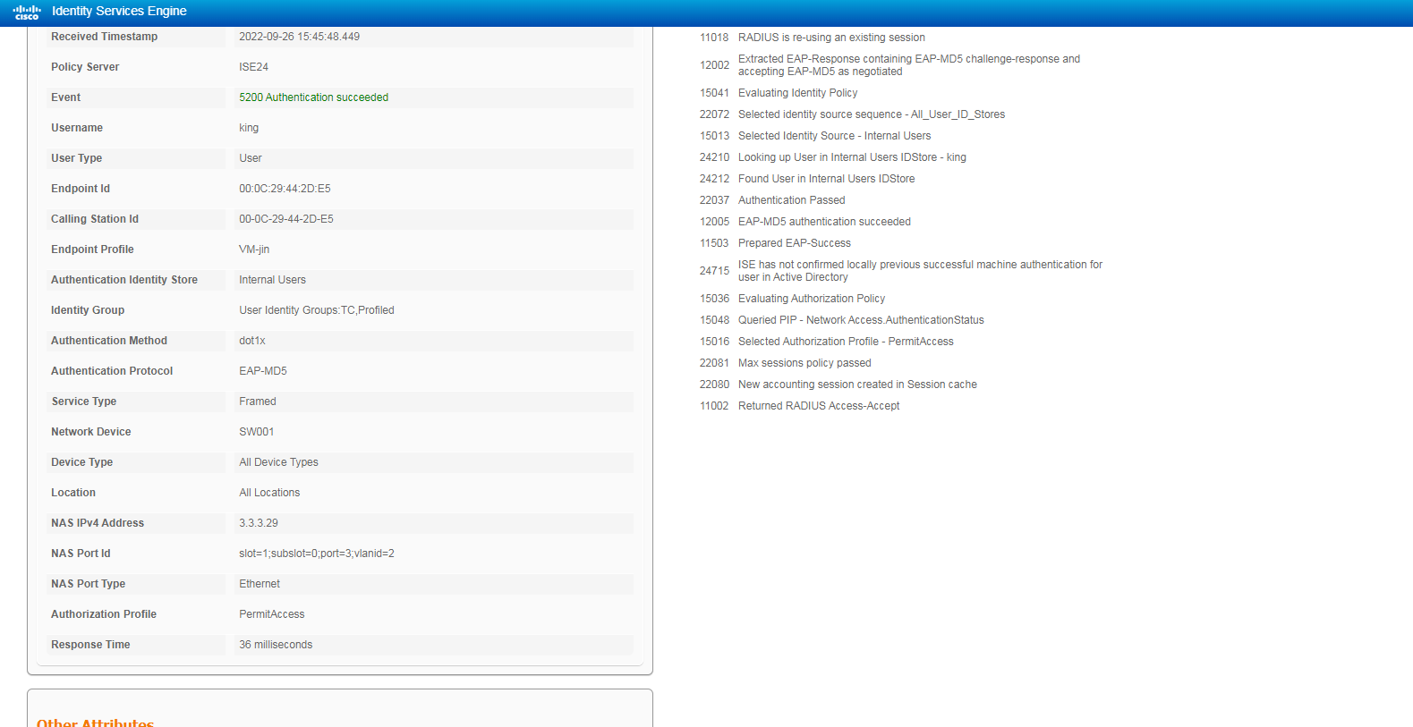
Verifying the configuration
1. Use the iNode client to verify that you can pass 802.1X authentication to come online after you enter the username and password. (Details not shown.)
2. On the ISE server, view information about the online user.
Figure 17 Viewing user access information
3. On the switch, use the display dot1x connection command to display information about online 802.1X authentication users.
<Switch> display dot1x connection
Total connections: 1
Slot ID: 1
User MAC address: 000c-2944-2de5
Access interface: GigabitEthernet1/0/3
Username: king
User access state: Successful
Authentication domain: ise
IPv4 address: 2.2.2.10
IPv4 address source: IP Source Guard
EAP packet identifier: 108
Authentication method: EAP
AAA authentication method: RADIUS
Initial VLAN: 2
Authorization untagged VLAN: N/A
Authorization tagged VLAN list: N/A
Authorization VSI: N/A
Authorization microsegment ID: N/A
Authorization ACL number/name: N/A
Authorization dynamic ACL name: N/A
Authorization user profile: N/A
Authorization CAR: N/A
Authorization URL: N/A
Authorization IPv6 URL: N/A
Authorization temporary redirect: Disabled
Start accounting: Successful
Real-time accounting-update failures: 0
Termination action: Default
Session timeout period: N/A
Online from: 2022/09/26 15:43:51
Online duration: 0h 0m 8s
The output shows that the user has passed 802.1X PAP authentication and come online.
Configuration files
#
dot1x
dot1x authentication-method eap
#
vlan 1
#
vlan 2
description toClients
arp snooping enable
#
vlan 3
description toAAAserver
#
interface Vlan-interface1
#
interface Vlan-interface2
description toClients
ip address 2.2.2.29 255.255.255.0
#
interface Vlan-interface3
description toAAAservers
ip address 3.3.3.29 255.255.255.0
#
interface GigabitEthernet1/0/2
port link-mode bridge
port access vlan 3
#
interface GigabitEthernet1/0/3
port link-mode bridge
port access vlan 2
dot1x
#
radius scheme ise
primary authentication 3.3.3.24 key cipher $c$3$2oLOvHdRilTBlb6n1yh3/MoXN8z/RMbctQ==
primary accounting 3.3.3.24 key cipher $c$3$fAhWH/rHm9hCcPq2PBWQa54YG9xKuQ1P0w==
timer realtime-accounting 20 second
user-name-format keep-original
#
#
domain test.com
authentication default radius-scheme ise
authorization default radius-scheme ise
accounting default radius-scheme ise
#
Example: Configuring 802.1X PEAP or EAP-TTLS authentication
In this example, the Cisco ISE server use a self-signed certificate to perform 802.1X authentication for the client and no client's certificate is required.
Configuring the switch
Configure the switch as described in "Configuring the switch," except that you must set the authentication method to EAP as follows:
[Switch] dot1x authentication-method EAP
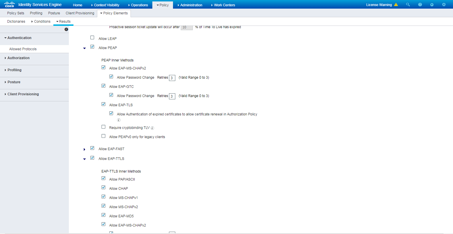
Configuring the ISE server
Configure the ISE server as described in "Configuring the ISE server," except that you must select Allow PEAP or Allow EAP-TTLS for the Allowed Protocols service.
Figure 18 Selecting the Allow PEAP or Allow EAP-TTLS authentication protocol
Verifying the configuration
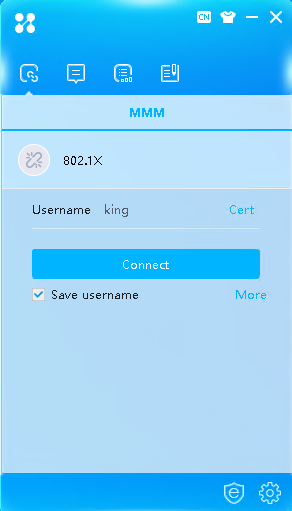
1. Use the iNode client to verify that you can pass 802.1X authentication to come online after you enter the username and password:
# Click More on the iNode client interface for 802.1X authentication.
Figure 19 iNode client interface
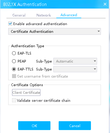
# Click the Advanced tab, select Enable advanced authentication, select PEAP or EAP-TTLS in the Authentication Type field, and then click OK.
Figure 20 Selecting authentication type PEAP
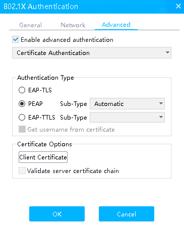
Figure 21 Selecting authentication type EAP-TTLS
# Enter the configured username and password and then click Connect. You can pass authentication and come online.
2. On the ISE server, view information about the online user.
Figure 22 Viewing user access information in 802.1X PEAP authentication
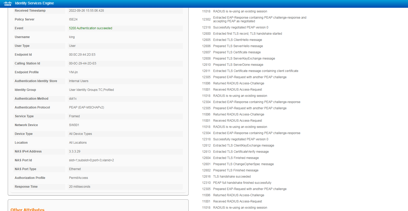
Figure 23 Viewing user access information in 802.1X EAP-TTLS authentication
3. On the switch, use the display dot1x connection command to display information about online 802.1X authentication users.
<Switch> display dot1x connection
Total connections: 1
Slot ID: 1
User MAC address: 000c-2944-2de5
Access interface: GigabitEthernet1/0/3
Username: king
User access state: Successful
Authentication domain: ise
IPv4 address: 2.2.2.10
IPv4 address source: IP Source Guard
EAP packet identifier: 108
Authentication method: EAP
AAA authentication method: RADIUS
Initial VLAN: 2
Authorization untagged VLAN: N/A
Authorization tagged VLAN list: N/A
Authorization VSI: N/A
Authorization microsegment ID: N/A
Authorization ACL number/name: N/A
Authorization dynamic ACL name: N/A
Authorization user profile: N/A
Authorization CAR: N/A
Authorization URL: N/A
Authorization IPv6 URL: N/A
Authorization temporary redirect: Disabled
Start accounting: Successful
Real-time accounting-update failures: 0
Termination action: Default
Session timeout period: N/A
Online from: 2022/09/26 15:43:51
Online duration: 0h 0m 8s
The output shows that the user has passed 802.1X PEAP or EAP-TTLS authentication and come online.
Configuration files
#
dot1x
dot1x authentication-method eap
#
vlan 1
#
vlan 2
description toClients
arp snooping enable
#
vlan 3
description toAAAserver
#
interface Vlan-interface1
#
interface Vlan-interface2
description toClients
ip address 2.2.2.29 255.255.255.0
#
interface Vlan-interface3
description toAAAservers
ip address 3.3.3.29 255.255.255.0
#
interface GigabitEthernet1/0/2
port link-mode bridge
port access vlan 3
#
interface GigabitEthernet1/0/3
port link-mode bridge
port access vlan 2
dot1x
#
radius scheme ise
primary authentication 3.3.3.24 key cipher $c$3$2oLOvHdRilTBlb6n1yh3/MoXN8z/RMbctQ==
primary accounting 3.3.3.24 key cipher $c$3$fAhWH/rHm9hCcPq2PBWQa54YG9xKuQ1P0w==
timer realtime-accounting 20 second
user-name-format keep-original
#
#
domain test.com
authentication default radius-scheme ise
authorization default radius-scheme ise
accounting default radius-scheme ise
#
Example: Configuring 802.1X EAP-TLS authentication
In this example, a CA certificate issued by the Windows server is used to perform 802.1X authentication for the client. For more information about installation and configurations of Windows server and CA service, see related documents.
Configuring the switch
Configure the switch as described in "Configuring the switch," except that you must set the authentication method to EAP as follows:
[Switch] dot1x authentication-method EAP
Configuring the ISE server
Configure the ISE server as described in "Configuring the ISE server," except that you must configure the following settings in this example:
1. On the ISE server, select Allow EAP-TLS for the Allowed Protocols service.
Figure 24 Selecting the Allow EAP-TLS authentication protocol
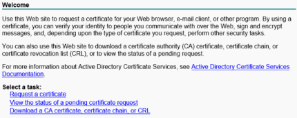
2. Download and install the root certificate:
# Open the Microsoft Active Directory Certificate Services web interface at https://CA_server_IP/certsrv. Click Download a CA certificate, certificate chain, or CRL.
For more information about Active Directory Certificate Services, see related documents.
Figure 25 Microsoft Active Directory Certificate Services web interface
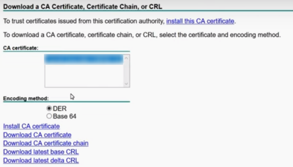
# Click Download CA certificate.
Figure 26 Downloading a CA certificate
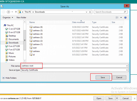
# Save the certificate file with file name certnew-root.cer to the local computer.
Figure 27 Saving the certificate file
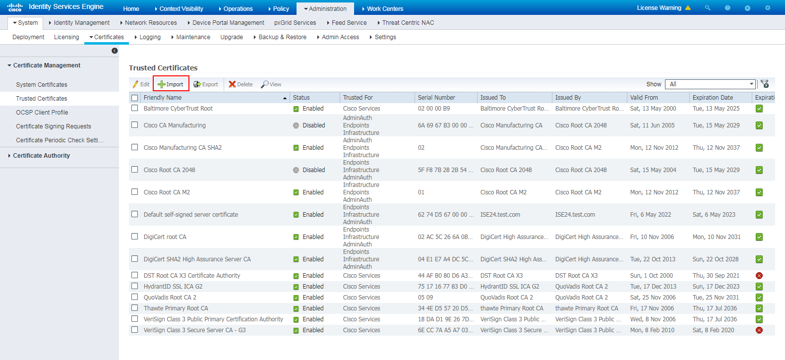
# Log in to the ISE server, navigate to the Administration > System > Certificates > Certificate Management > Trusted Certificates page, and then click Import.
Figure 28 Certificate import page
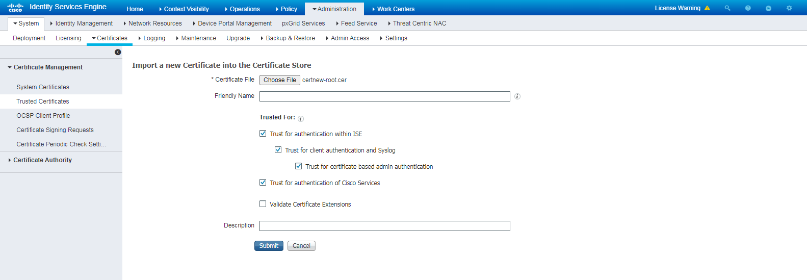
# On the page that opens, click Choose File, select and import the downloaded root certificate certnew-root.cer, and then click Submit.
Figure 29 Importing the downloaded root certificate
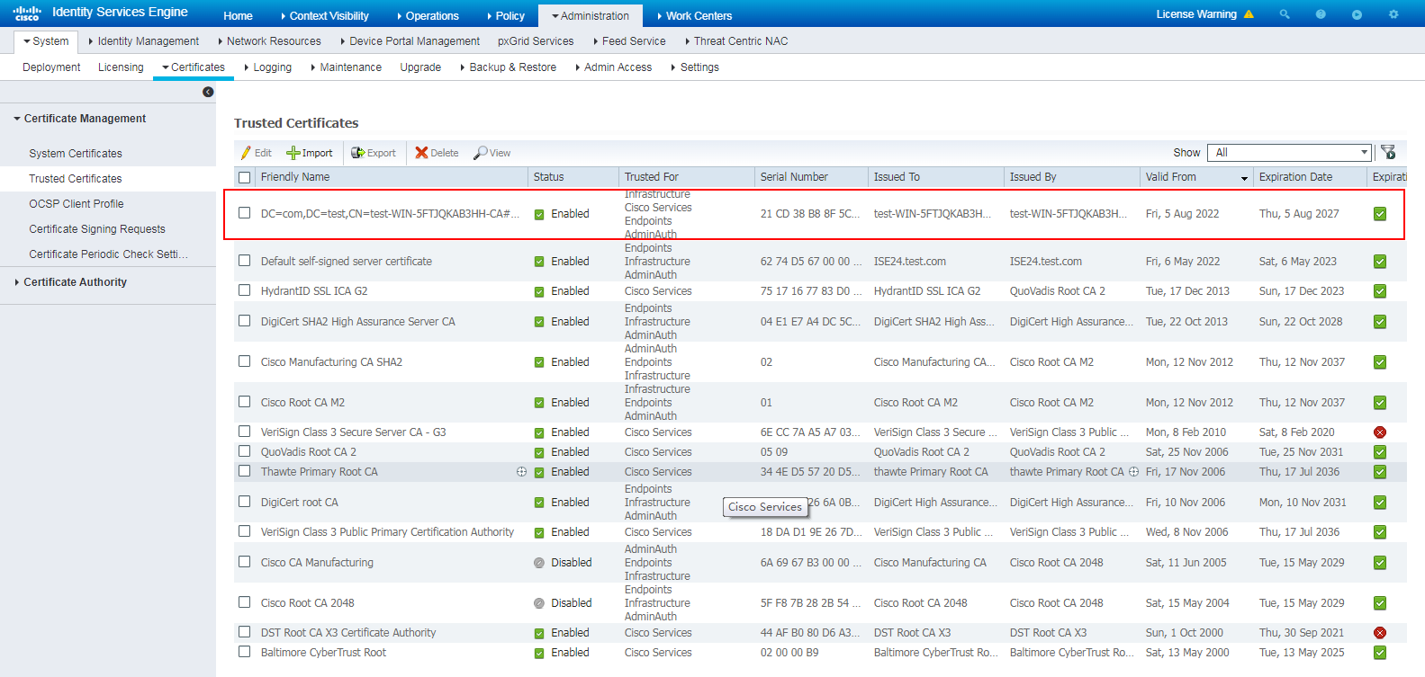
# View the imported root certificate.
Figure 30 Viewing the imported root certificate
3. Request and install the personal certificate:
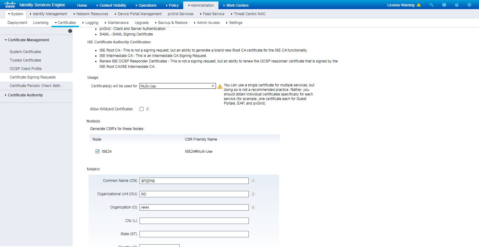
# Navigate to the Administration > System > Certificates > Certificate Management > Certificate Signing Requests page of the ISE server.
# Select Multi-Use in the Certificate(s) will be used for field and configure other parameters.
Figure 31 Configuring a certificate signing request
# Click Generate.
Figure 32 Requesting for generation of a certificate

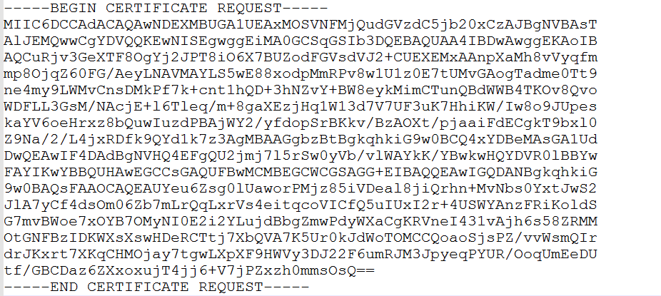
# In the dialog box that opens, click Export.
# Open the generated certificate file ISE24MultiUse.pem, and then copy the certificate content.
Figure 33 Viewing the generated certificate file
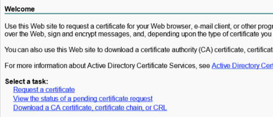
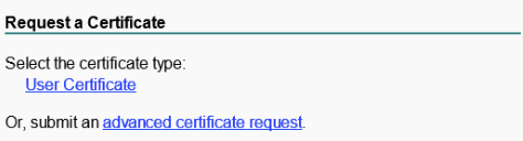
# Open the Microsoft Active Directory Certificate Services web interface. Click Request a certificate.
Figure 34 Microsoft Active Directory Certificate Services web interface
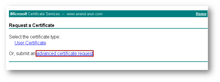
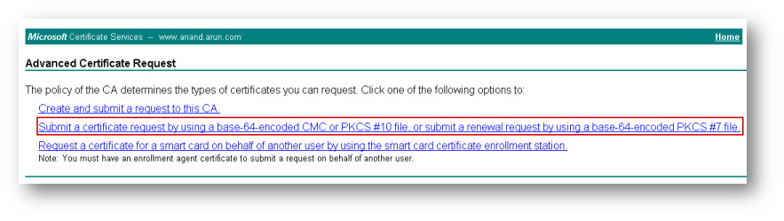
# Select advanced certificate request.
Figure 35 Selecting advanced certificate request
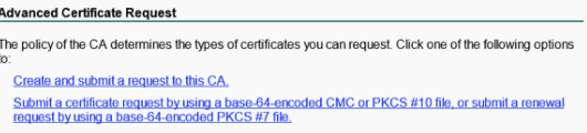
# Click Submit a certificate request by using a base-64-encoded CMC or PKCS #10 file or submit a renewal request by using a base-64-encoded PKCS #7 file.
Figure 36 Selecting an option for the advanced certificate request
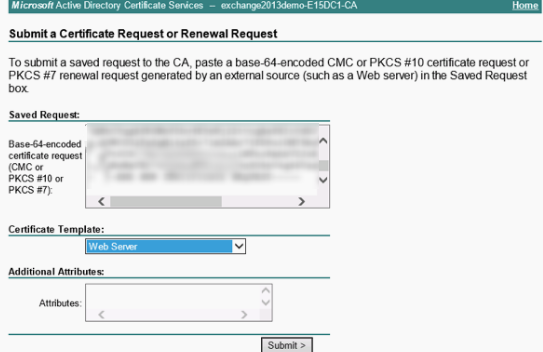
# Paste the copied certificate content to the text box in the Saved Request area. Select a certificate template, and then click Submit.
In this example, certificate template Web Server is used.
Figure 37 Submitting the certificate request
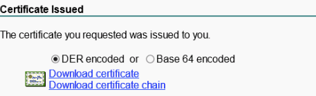
# Select Base 64 encoded, click Download certificate, and save the certificate with file name certnew-server.cer.
Figure 38 Downloading the certificate
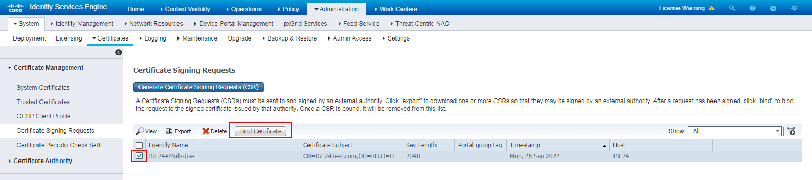
# Navigate to the Administration > System > Certificates > Certificate Management > Certificate Signing Requests page of the ISE server.
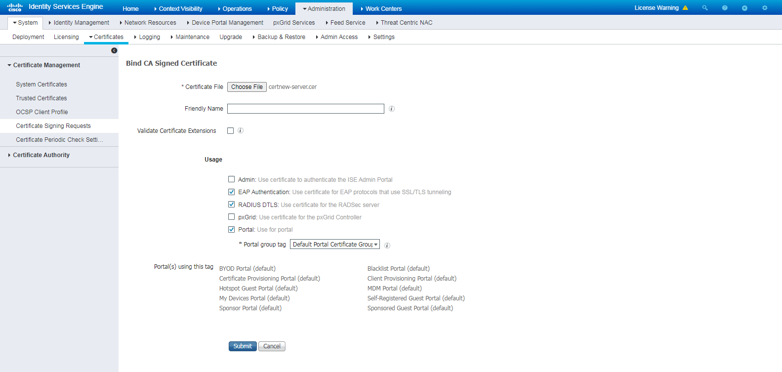
# Select the created certificate signing request, and then click Bind Certificate.
Figure 39 Binding the certificate
# On the page that opens, select and import the downloaded personal certificate certnew-server.cer, select EAP Authentication in the Usage field, and configure other parameters.
Figure 40 Importing the downloaded personal certificate
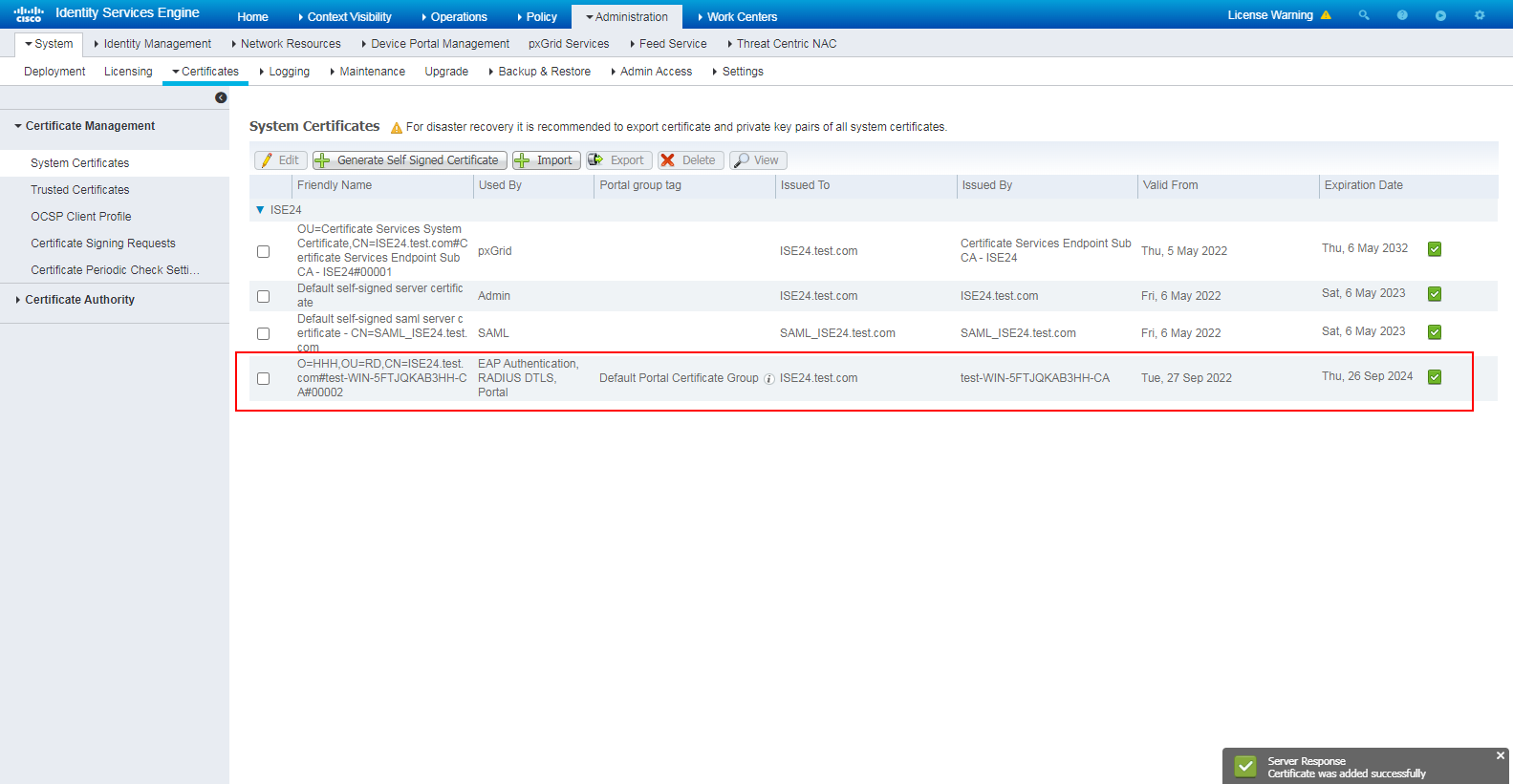
# Click Submit, and then view the imported personal certificate.
Figure 41 Viewing the imported personal certificate
Configuring the Windows client
1. Install the root certificate:
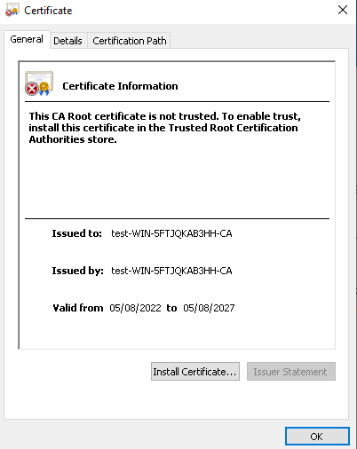
# On the Windows client, double-click root certificate certnew-root.cer downloaded in step 2 when configuring the ISE server, and click Install Certificate… on the window that opens.
Figure 42 Installing the root certificate
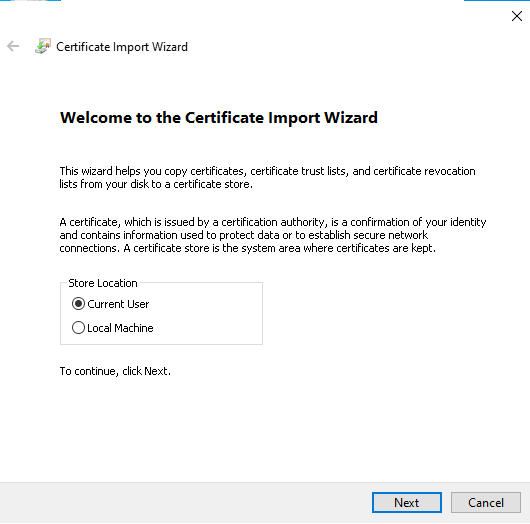
# On the wizard, select Current User, and then click Next.
Figure 43 Selecting the store location
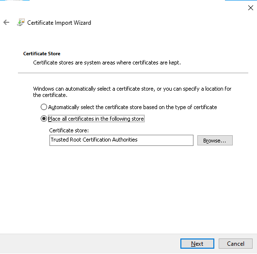
# Select Place all certificates in the following store, select Trusted Root Certification Authorities in the Certificate store field, and then click Next.
Figure 44 Specifying the certificate store
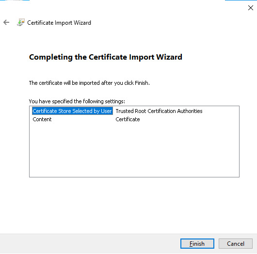
# Click Finish.
Figure 45 Completing certificate import
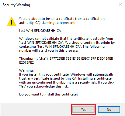
# In the security warning dialog box that opens, click Yes.
Figure 46 Security warning
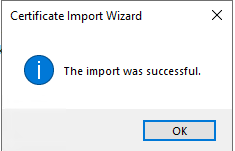
# View the import result.
Figure 47 Successful import
2. Request and install the user's certificate:
# Open the Microsoft Active Directory Certificate Services web interface at https://CA_server_IP/certsrv. Then click Request a certificate.
Figure 48 Microsoft Active Directory Certificate Services web interface

# On the page that opens, click advanced certificate request.
Figure 49 Selecting advanced certificate request
# Click Create and submit a request to this CA.
Figure 50 Selecting an option for the advanced certificate request
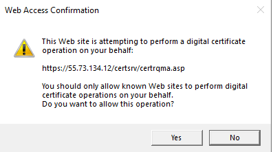
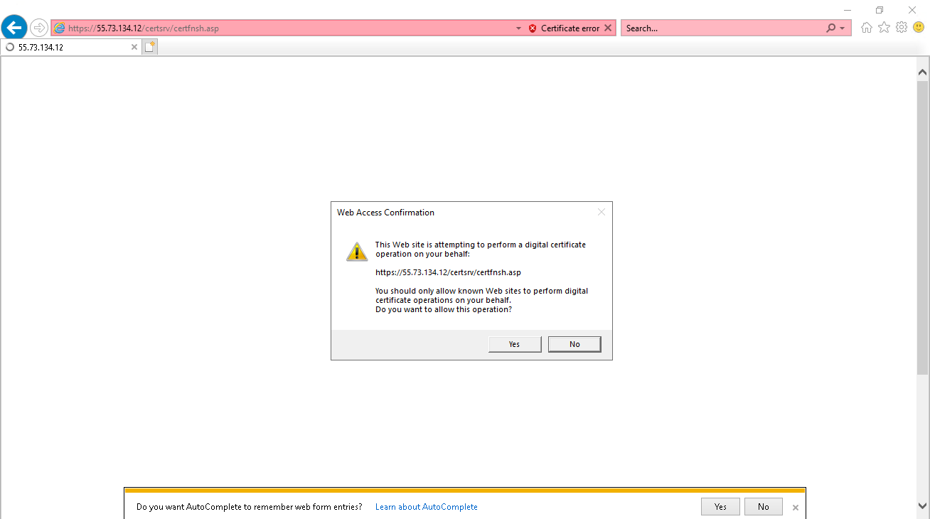
# In the dialog box that opens, click Yes.
Figure 51 Web access confirmation
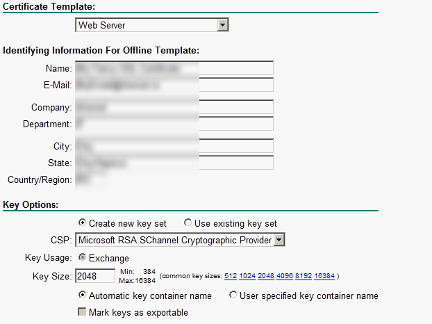
# Configure the related parameters, and click Submit.
Figure 52 Requesting an advanced certificate
# In the dialog box that opens, click Yes and the certificate will be installed.
Figure 53 Web access confirmation
3. Configure the iNode client:
# Click More on the iNode client interface for 802.1X authentication.
Figure 54 iNode client interface
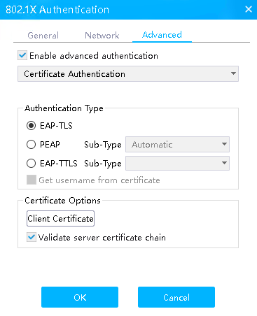
# Click the Advanced tab, select Enable advanced authentication, select EAP-TLS in the Authentication Type field, and then click Client Certificate in the Certificate Options field.
Figure 55 Selecting authentication type EAP-TLS
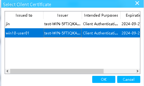
# On the Select Client Certificate page that opens, select the imported client certificate, and then click OK.
Figure 56 Selecting a client certificate
Verifying the configuration
1. Use the iNode client to verify that you can pass 802.1X authentication to come online after you enter the username and password.
# Enter the configured username and password and then click Connect.
Figure 57 iNode connection
# Verify that you can come online successfully.
Figure 58 Successful connection
2. On the ISE server, view information about the online user.
Figure 59 Viewing user access information
3. On the switch, use the display dot1x connection command to display information about online 802.1X authentication users.
<Switch> display dot1x connection
Total connections: 1
Slot ID: 1
User MAC address: 000c-2944-2de5
Access interface: GigabitEthernet1/0/3
Username: king
User access state: Successful
Authentication domain: ise
IPv4 address: 2.2.2.10
IPv4 address source: IP Source Guard
EAP packet identifier: 227
Authentication method: EAP
AAA authentication method: RADIUS
Initial VLAN: 2
Authorization untagged VLAN: N/A
Authorization tagged VLAN list: N/A
Authorization VSI: N/A
Authorization microsegment ID: N/A
Authorization ACL number/name: N/A
Authorization dynamic ACL name: N/A
Authorization user profile: N/A
Authorization CAR: N/A
Authorization URL: N/A
Authorization IPv6 URL: N/A
Authorization temporary redirect: Disabled
Start accounting: Successful
Real-time accounting-update failures: 0
Termination action: Default
Session timeout period: N/A
Online from: 2022/09/28 15:17:15
Online duration: 0h 0m 7s
The output shows that the user has passed 802.1X EAP-TLS authentication and come online.
Configuration files
#
dot1x
dot1x authentication-method eap
#
vlan 1
#
vlan 2
description toClients
arp snooping enable
#
vlan 3
description toAAAserver
#
interface Vlan-interface1
#
interface Vlan-interface2
description toClients
ip address 2.2.2.29 255.255.255.0
#
interface Vlan-interface3
description toAAAservers
ip address 3.3.3.29 255.255.255.0
#
interface GigabitEthernet1/0/2
port link-mode bridge
port access vlan 3
#
interface GigabitEthernet1/0/3
port link-mode bridge
port access vlan 2
dot1x
#
radius scheme ise
primary authentication 3.3.3.24 key cipher $c$3$2oLOvHdRilTBlb6n1yh3/MoXN8z/RMbctQ==
primary accounting 3.3.3.24 key cipher $c$3$fAhWH/rHm9hCcPq2PBWQa54YG9xKuQ1P0w==
timer realtime-accounting 20 second
user-name-format keep-original
#
#
domain test.com
authentication default radius-scheme ise
authorization default radius-scheme ise
accounting default radius-scheme ise
#
Example: Configuring 802.1X EAP-FAST authentication
Configuring the switch
Configure the switch as described in "Configuring the switch," except that you must configure the following settings in this example:
# Set the authentication method to EAP.
[Switch] dot1x authentication-method EAP
# Disable the online user handshake feature and the 802.1X multicast trigger feature on the interface connected to the client.
[Switch-GigabitEthernet1/0/3]undo dot1x handshake
[Switch-GigabitEthernet1/0/3]undo dot1x multicast-trigger
Configuring the ISE server
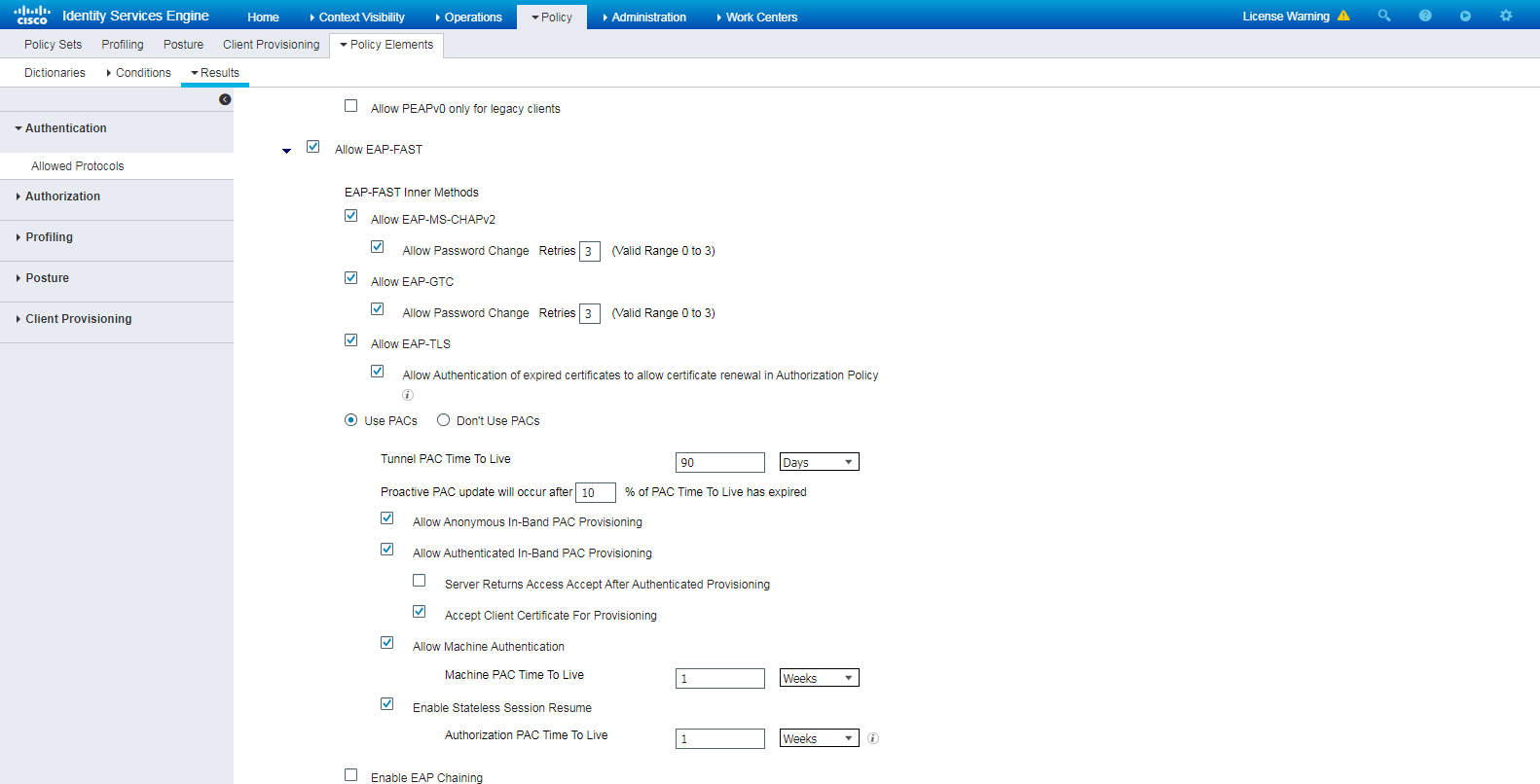
Configure the ISE server as described in "Configuring the ISE server," except that you must select Allow EAP-FAST for the Allowed Protocols service.
Figure 60 Selecting the Allow EAP-FAST authentication protocol

Configuring the Cisco AnyConnect client
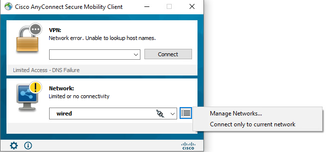
Install the Cisco AnyConnect client in the Predeploy or Web Deploy method. This example uses the Web Deploy method.
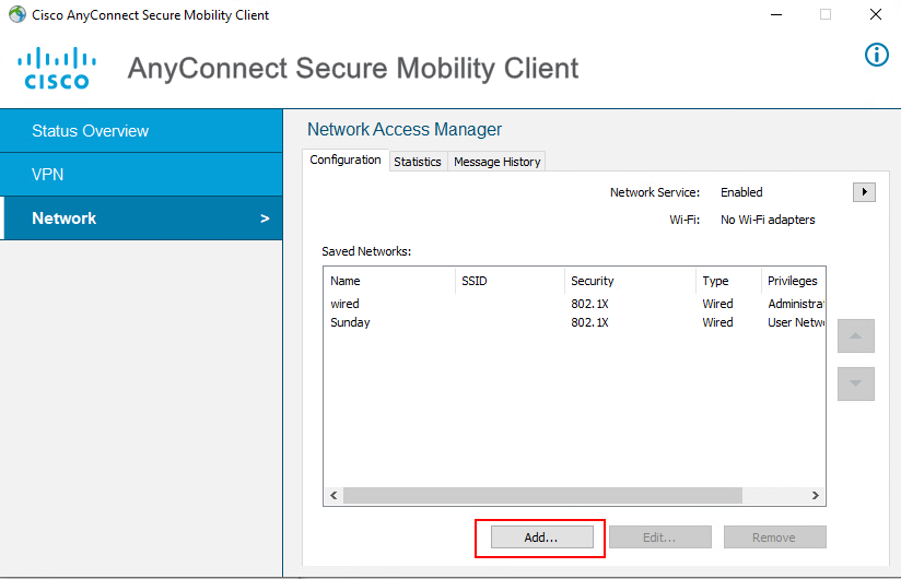
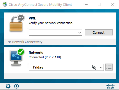
# On the Cisco AnyConnect Secure Mobility Client window, select wired in the Network field, and then select Manage Networks….
Figure 61 Selecting wired connection
# On the window that opens, click Add….
Figure 62 Adding a connection
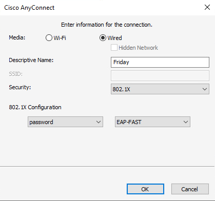
# On the window that opens, configure the information for the connection.
Figure 63 Configuring the connection
Verifying the configuration
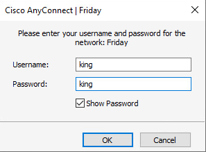
1. Use the Cisco AnyConnect client to verify that the connection can be successfully established after you enter the username and password.
# Enter the configured username and password and then click OK.
Figure 64 Initiating connection on the client
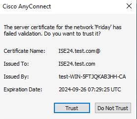
# In the dialog box that opens, click Trust.
Figure 65 Trusting the server certificate
# Verify that the connection can be successfully established.
Figure 66 Successful connection
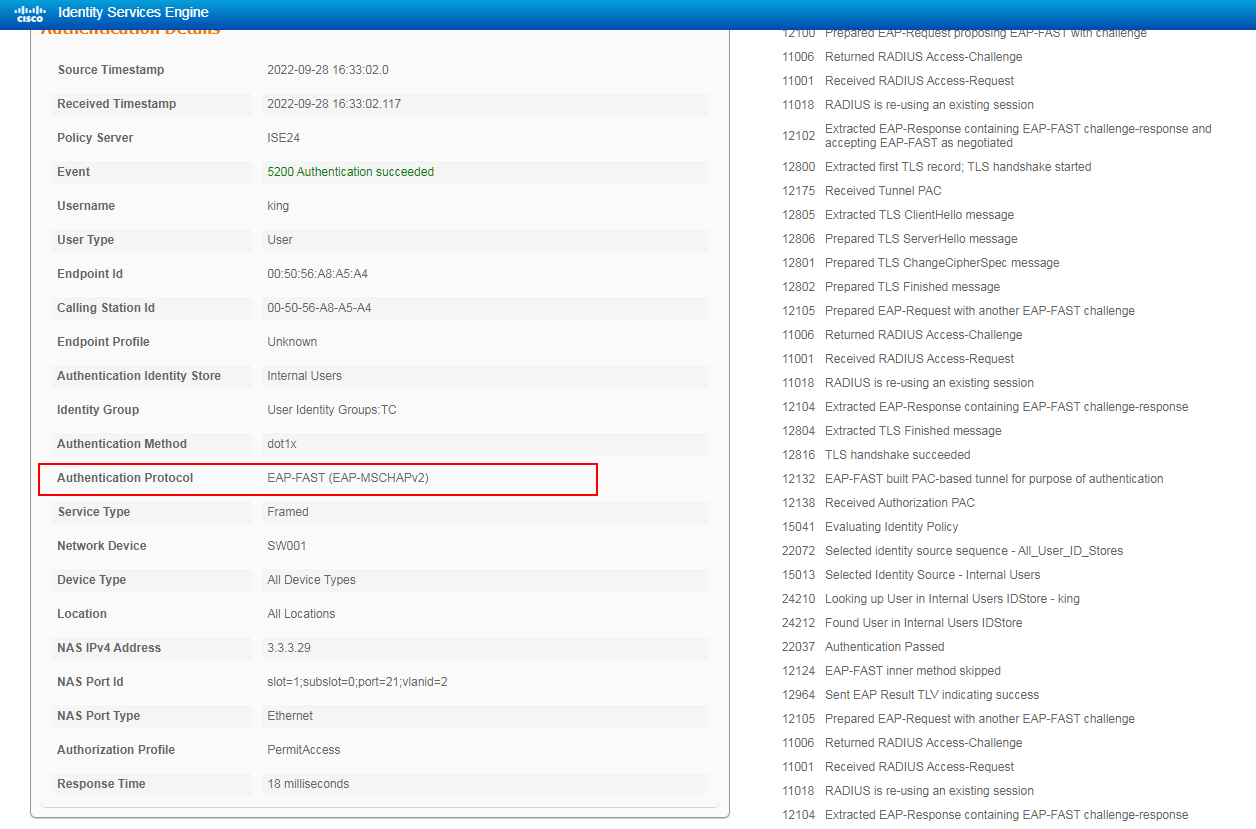
2. On the ISE server, view information about the online user.
Figure 67 Viewing user access information
3. On the switch, use the display dot1x connection command to display information about online 802.1X authentication users.
<Switch> display dot1x connection
Total connections: 1
Slot ID: 1
User MAC address: 000c-2944-2de5
Access interface: GigabitEthernet1/0/3
Username: king
User access state: Successful
Authentication domain: ise
IPv4 address: 2.2.2.10
IPv4 address source: IP Source Guard
EAP packet identifier: 227
Authentication method: EAP
AAA authentication method: RADIUS
Initial VLAN: 2
Authorization untagged VLAN: N/A
Authorization tagged VLAN list: N/A
Authorization VSI: N/A
Authorization microsegment ID: N/A
Authorization ACL number/name: N/A
Authorization dynamic ACL name: N/A
Authorization user profile: N/A
Authorization CAR: N/A
Authorization URL: N/A
Authorization IPv6 URL: N/A
Authorization temporary redirect: Disabled
Start accounting: Successful
Real-time accounting-update failures: 0
Termination action: Default
Session timeout period: N/A
Online from: 2022/09/28 15:17:15
Online duration: 0h 0m 7s
The output shows that the user has passed 802.1X EAP-FAST authentication and come online.
Configuration files
#
dot1x
dot1x authentication-method eap
#
vlan 1
#
vlan 2
description toClients
arp snooping enable
#
vlan 3
description toAAAserver
#
interface Vlan-interface1
#
interface Vlan-interface2
description toClients
ip address 2.2.2.29 255.255.255.0
#
interface Vlan-interface3
description toAAAservers
ip address 3.3.3.29 255.255.255.0
#
interface GigabitEthernet1/0/2
port link-mode bridge
port access vlan 3
#
interface GigabitEthernet1/0/3
port link-mode bridge
port access vlan 2
dot1x
undo dot1x handshake
undo dot1x multicast-trigger
#
#
radius scheme ise
primary authentication 3.3.3.24 key cipher $c$3$2oLOvHdRilTBlb6n1yh3/MoXN8z/RMbctQ==
primary accounting 3.3.3.24 key cipher $c$3$fAhWH/rHm9hCcPq2PBWQa54YG9xKuQ1P0w==
timer realtime-accounting 20 second
user-name-format keep-original
#
#
domain test.com
authentication default radius-scheme ise
authorization default radius-scheme ise
accounting default radius-scheme ise
#
Example: Configuring MAC authentication
Network configuration
As shown in Figure 68, configure the switch to work in conjunction with the Cisco ISE server to perform MAC authentication for the client. The client must pass MAC authentication to access network resources.
Configure the switch as follows:
· Use the Cisco ISE server as the RADIUS server to perform MAC authentication for the client.
· Use the MAC address of the client as the username and password for MAC authentication.

Hardware and software versions used
This configuration example was created and verified on the following hardware and software versions:
|
Hardware |
Software version |
|
Switch (S5560X) |
R6618P27 |
|
Authentication server |
Cisco ISE V2.4.0.357 patch 8 |
|
Client operating system |
Windows 10 21H2 |
|
Authentication client |
iNode PC 7.3 (E513) |
Procedures
Prerequisites
This example provides only the configuration for authentication. Make sure that the client, switch, and server have network connectivity to communicate with one another.
Configuring the switch
# Create VLAN 2 and VLAN-interface 2, and assign an IP address to the VLAN interface.
<Switch> system-view
[Switch] vlan 2
[Switch-vlan2] quit
[Switch] interface Vlan-interface 2
[Switch-Vlan-interface2] ip address 2.2.2.29 255.255.255.0
[Switch-Vlan-interface2] quit
# Assign GigabitEthernet 1/0/3 to VLAN 2 and enable MAC authentication on GigabitEthernet 1/0/3.
[Switch]interface GigabitEthernet 1/0/3
[Switch-GigabitEthernet1/0/3] port access vlan 2
[Switch-GigabitEthernet1/0/3] MAC-authentication
[Switch-GigabitEthernet1/0/3] quit
# Specify ISP domain test.com as the MAC authentication domain.
[Switch] MAC-authentication domain test.com
# Use MAC-based user accounts for MAC authentication users, include hyphens in the MAC addresses, and specify letters in upper case.
By default, the device uses a user's lower-case MAC address without hyphens as the username and password for MAC authentication of the user. Make sure the username and password of the user configured on the switch and the ISE server are the same.
[Switch] mac-authentication user-name-format mac-address with-hyphen uppercase
# Enable MAC authentication globally.
If you do not specify an authentication method for MAC authentication by using the mac-authentication authentication-method command, the device uses PAP for MAC authentication by default.
[Switch] MAC-authentication
Configuring the ISE server
1. View the MAC address (physical address) of the client connected to the switch.
Figure 69 Viewing the MAC address of the client
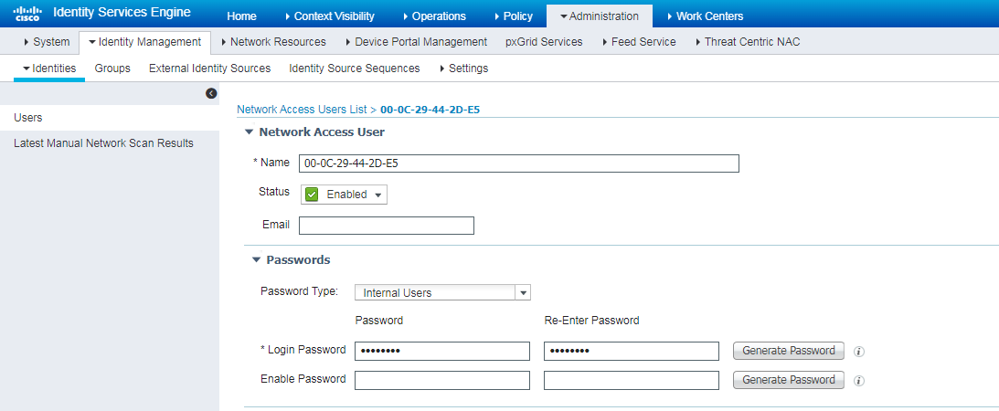
2. Create a user by using one of the following methods:
¡ Navigate to the Administration > Identity Management > Identities page. In the left pane, right-click Users and then click Add to create an user and specify login password for the user.
In this example, the name and login password of the user are both 00-0C-29-44-2D-E5.
Figure 70 Creating a user
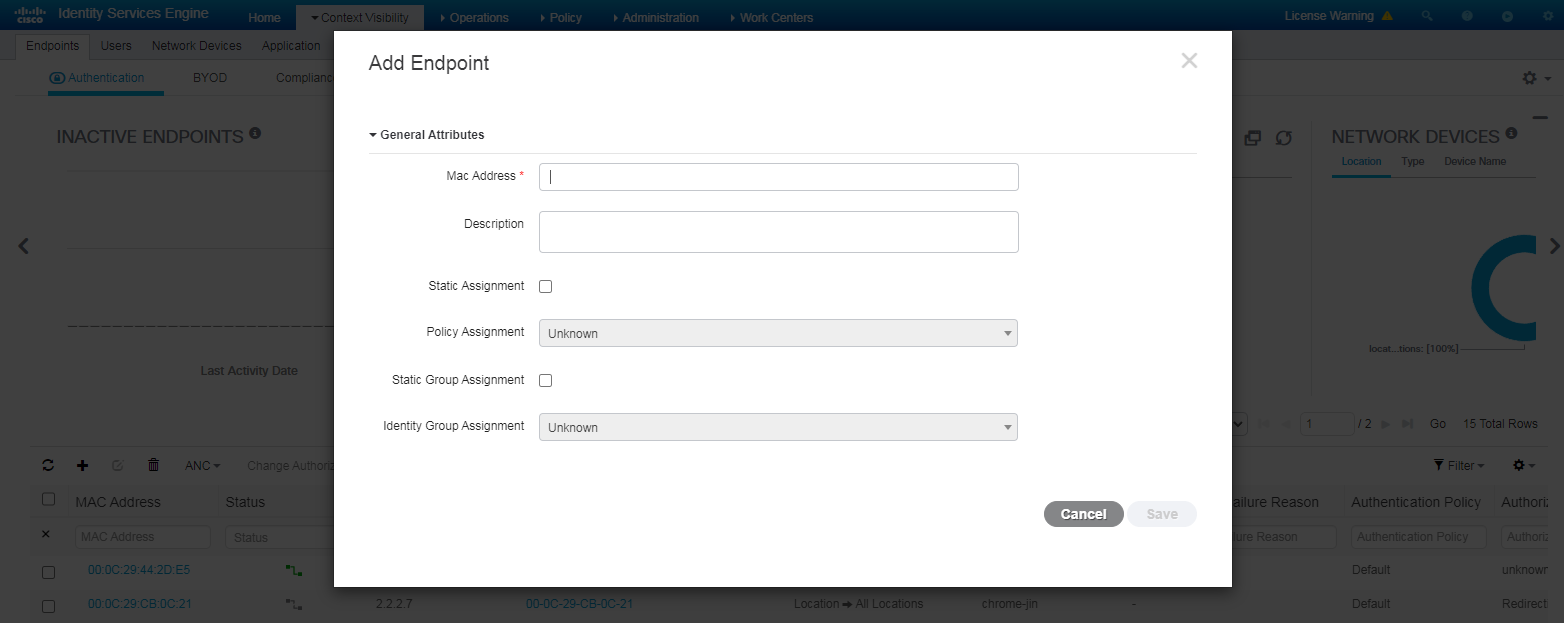
¡ Navigate to the Context Visibility > Endpoints page, enter the MAC address of the client for MAC authentication when adding an endpoint.
Figure 71 Adding an endpoint
3. Configure authentication protocols:
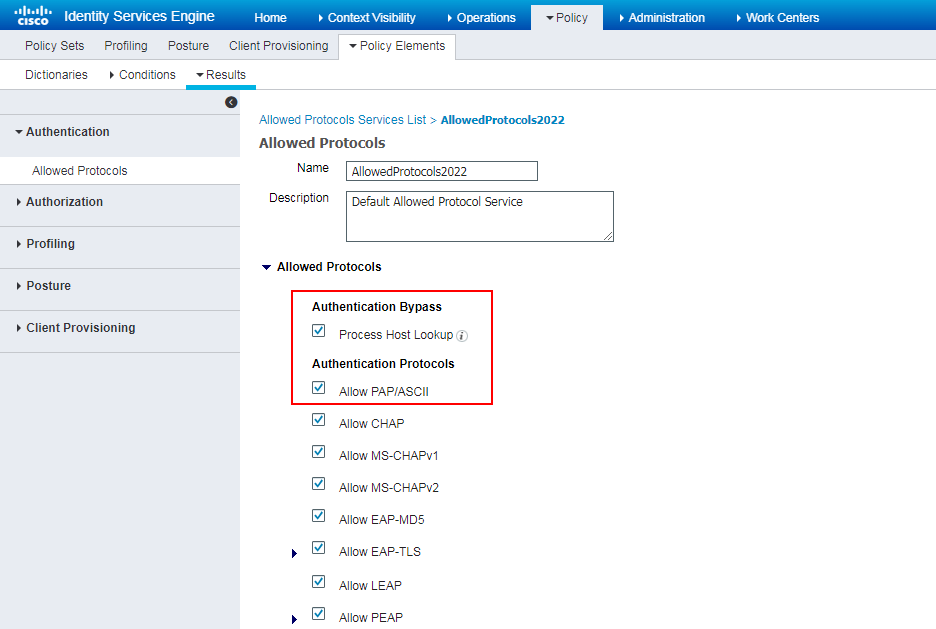
# Navigate to the Policy > Policy Elements > Results > Authentication > Allowed Protocols page. Right-click Allowed Protocols and then click Add to add a new allowed protocols service.
# Configure the service name as AllowedProtocols2022, make sure Process Host Lookup in the Authentication Bypass field and Allow PAP/ASCII in the Authentication Protocols field are selected.
Figure 72 Adding an allowed protocols service
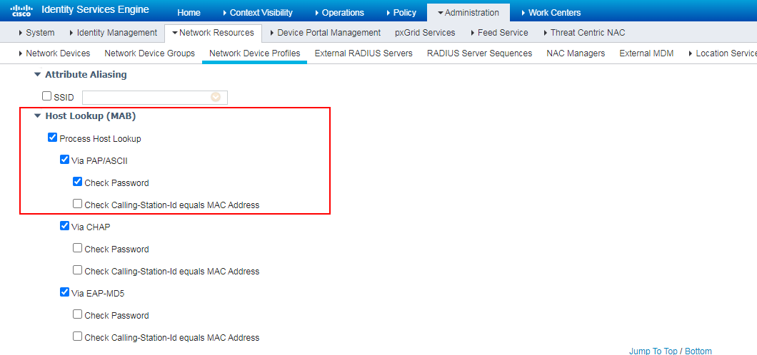
4. Configure a network device profile:
# Navigate to the Administration > Network Resources > Network Device Profiles page.
# Select the system-provided network device profile Cisco, click Duplicate, and then configure a new network switch profile. Make sure Check Password is selected in the Host Lookup (MAB) area.
Figure 73 Configuring a network device profile
5. Configure a policy set (group of authentication and authorization policies):
# Navigate to the Policy > Policy Sets page.
# Click the + icon to add a policy set named MAC Authentication.
# Specify the conditions as Wired_MAB.
Figure 74 Configuring a policy set
![]()
Verifying the configuration
1. Ping the server from the client to verify that you can successfully come online.
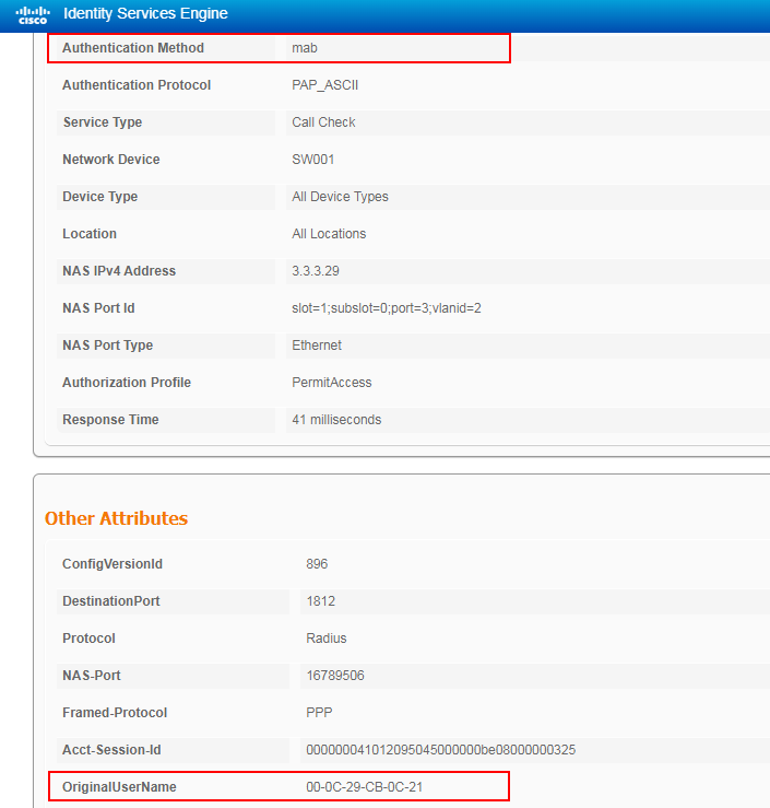
2. On the ISE server, view information about the online user.
Figure 75 Viewing user access information
3. On the switch, use the display mac-authentication connection command to display information about online MAC authentication users.
<Switch> display mac-authentication connection
Total connections: 1
Slot ID: 1
User MAC address: 000c-2944-2de5
Access interface: GigabitEthernet1/0/3
Username: 00-0C-29-44-2D-E5
User access state: Successful
Authentication domain: test.com
IPv4 address: 2.2.2.10
IPv4 address source: IP Source Guard
Initial VLAN: 2
Authorization untagged VLAN: N/A
Authorization tagged VLAN: N/A
Authorization VSI: N/A
Authorization microsegment ID: N/A
Authorization ACL number/name: N/A
Authorization dynamic ACL name: N/A
Authorization user profile: N/A
Authorization CAR: N/A
Authorization URL: N/A
Authorization IPv6 URL: N/A
Authorization temporary redirect: Disabled
Start accounting: Successful
Real-time accounting-update failures: 0
Termination action: Default
Session timeout period: N/A
Offline detection: 300 sec (command-configured)
Online from: 2022/10/12 17:48:35
Online duration: 0h 8m 9s
Port-down keep online: Disabled (offline)
The output shows that the user has passed MAC authentication and come online.
Configuration files
#
mac-authentication domain test.com
mac-authentication user-name-format mac-address with-hyphen uppercase
#
#
vlan 2
description toClients
arp snooping enable
#
vlan 3
description toAAAserver
#
interface Vlan-interface2
description toClients
ip address 2.2.2.29 255.255.255.0
#
interface Vlan-interface3
description toAAAservers
ip address 3.3.3.29 255.255.255.0
#
interface GigabitEthernet1/0/2
port link-mode bridge
port access vlan 3
#
interface GigabitEthernet1/0/3
port link-mode bridge
port access vlan 2
MAC-authentication
#
radius scheme ise
primary authentication 3.3.3.24 key cipher $c$3$2oLOvHdRilTBlb6n1yh3/MoXN8z/RMbctQ==
primary accounting 3.3.3.24 key cipher $c$3$fAhWH/rHm9hCcPq2PBWQa54YG9xKuQ1P0w==
user-name-format keep-original
#
#
domain test.com
authentication default radius-scheme ise
authorization default radius-scheme ise
accounting default radius-scheme ise
#
Example: Configuring portal authentication
Network configuration
As shown in Figure 76, configure the switch to work in conjunction with the Cisco ISE server to perform portal authentication for the client. The client must pass portal authentication to access network resources.
Configure the switch as follows:
· Use the Cisco ISE server as the RADIUS server and portal authentication server to perform portal authentication for the client.
· Use Centralized Web Authentication (CWA), in which the user is redirected to the portal authentication page for performing portal authentication after MAC authentication failed.

Hardware and software versions used
This configuration example was created and verified on the following hardware and software versions:
|
Hardware |
Software version |
|
Switch (S5560X) |
R6618P27 |
|
Authentication server |
Cisco ISE V2.4.0.357 patch 8 |
|
Client operating system |
Windows 10 21H2 |
|
Authentication client |
iNode PC 7.3 (E513) |
Procedures
Prerequisites
This example provides only the configuration for authentication. Make sure that the client, switch, and server have network connectivity to communicate with one another.
Configuring the switch
Because CWA is based on MAC authentication, configure the switch as described in "Configuring the switch," except that you must configure the following settings in this example:
# Create an ACL so that the client can access only necessary IP addresses such as the IP address of the CWA server and the IP address of the DNS server.
[Switch]acl number 3000
[Switch-acl-ipv4-adv-3000]dis th
#
acl advanced 3000
rule 0 permit ip destination 3.3.3.24 0
rule 2 permit ip destination 3.3.3.12 0
rule 6 permit ip destination 2.2.2.0 0.0.0.255
#
Return
Configuring the ISE server
Because CWA is based on MAC authentication, configure the ISE server as described in "Configuring the ISE server," except that you must configure the following settings in this example:
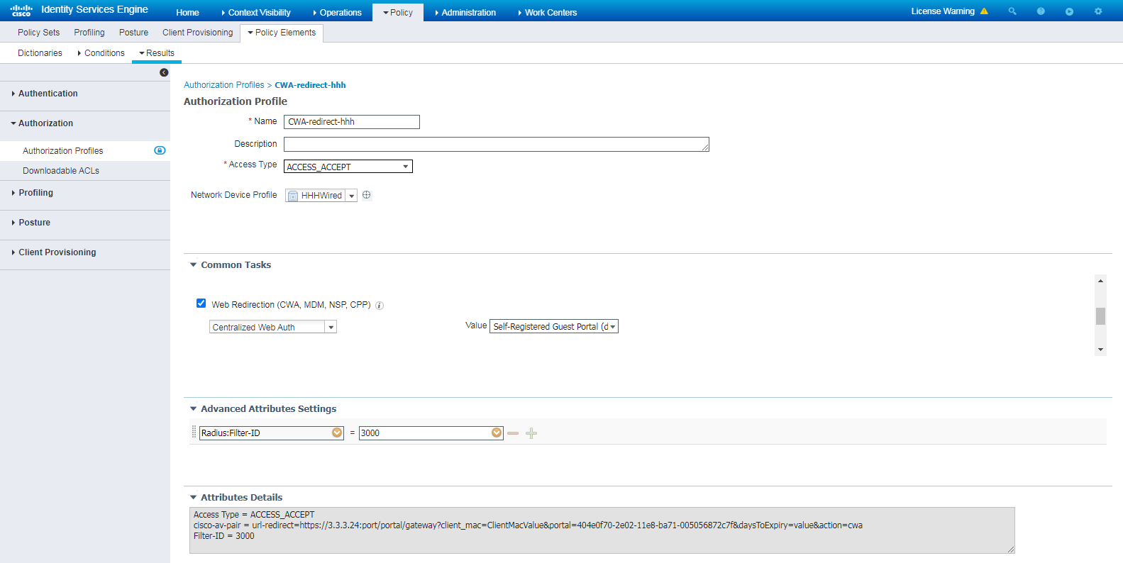
1. Create an authorization profile:
# Navigate to the Policy > Policy Elements > Results > Authorization > Authorization Profiles page.
# Create an authorization profile named CWA-redirect-hhh, select Web Redirection (CWA, MDM, NSP, CPP), and then select Centralized Web Auth.
Figure 77 Creating an authorization profile
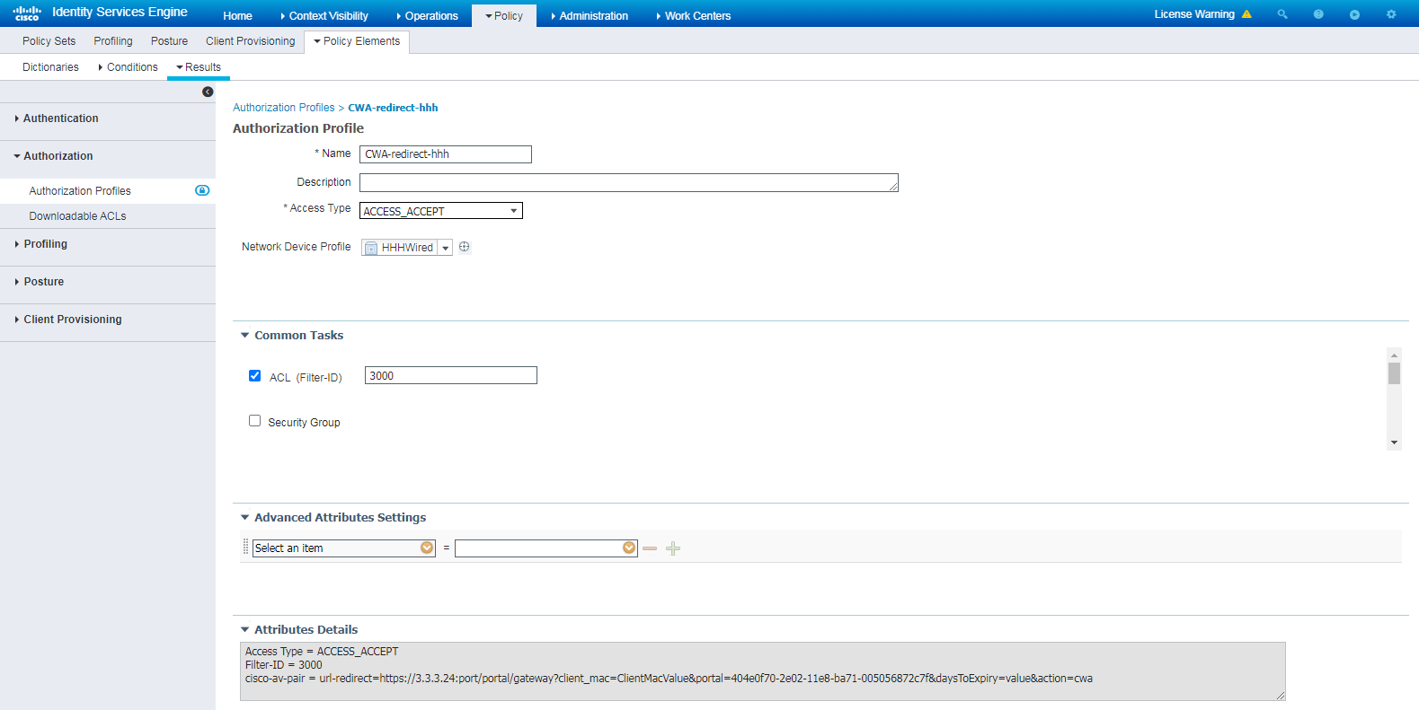
# Select the ACL (Filter-ID) option, and enter the ACL number to be associated with the client in the field. In this example, the ACL number is 3000.
Figure 78 Configuring the ACL
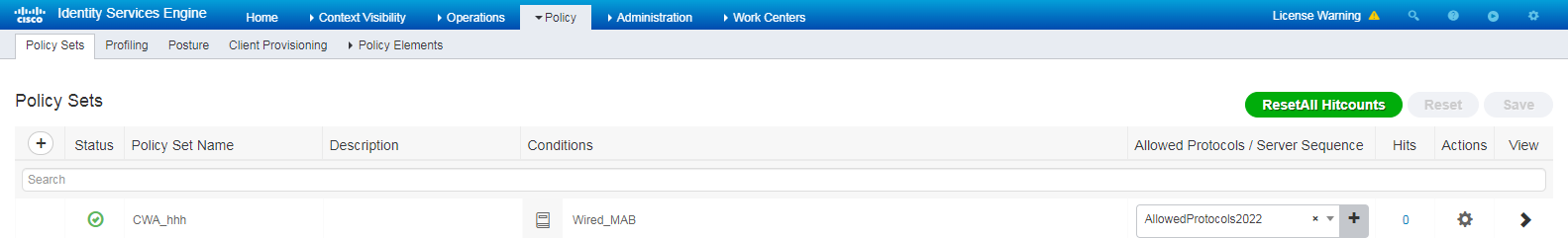
2. Configure a policy set:
# Navigate to the Policy > Policy Sets page.
# Click the + icon to add a policy set named CWA_hhh.
# Specify the conditions as Wired_MAB.
Figure 79 Configuring an authentication and authorization policy
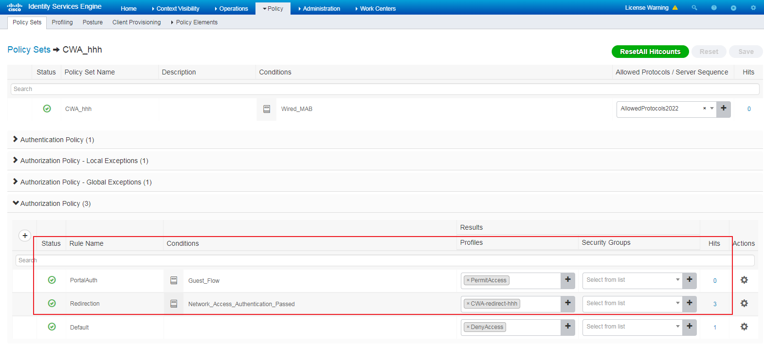
# Click the + icon in the Authorization Policy area, create authorization policies Redirection and PortalAuth, as shown in Figure 80.
Authorized policy Redirection is used for redirecting users to the CWA page. Authorized policy PortalAuth is used for allowing access of users who enter the correct usernames and passwords on the CWA page.
Figure 80 Creating authorization policies
Verifying the configuration
1. Verify that you can be redirected to the CWA page:
# Open a browser on the client, randomly type an address in the address bar, and then press Enter.
# Verify that you are redirected to the CWA page.
Figure 81 Web redirect
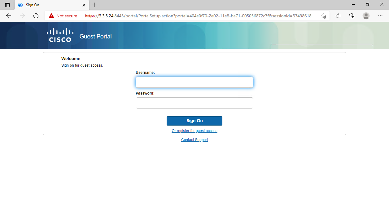
# Enter the username and password, and then click Sign On.
Figure 82 Entering the username and password
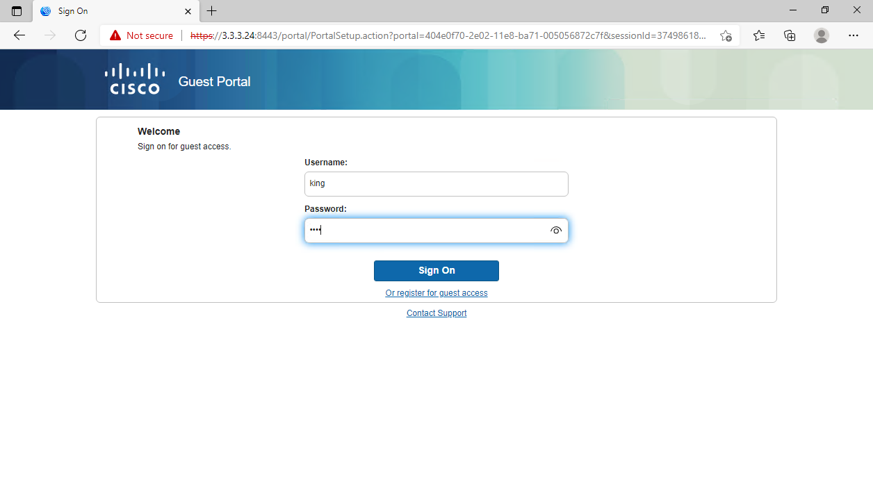
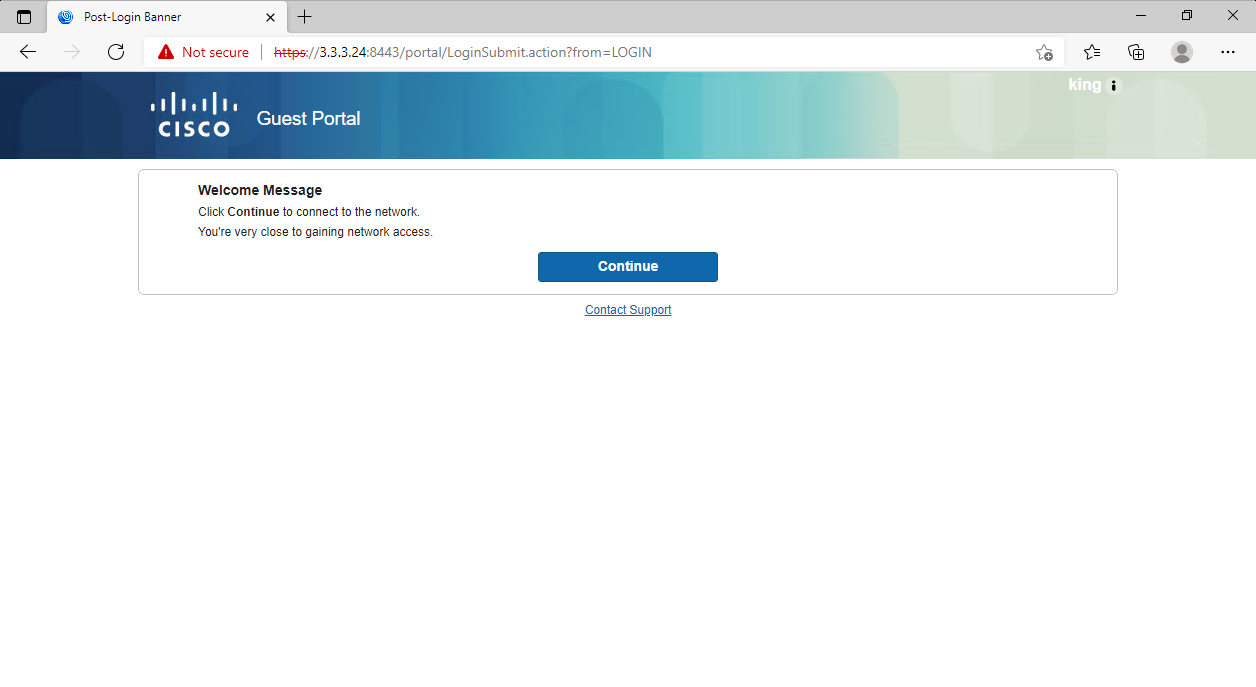
# Click Continue.
Figure 83 Continuing to gain network access
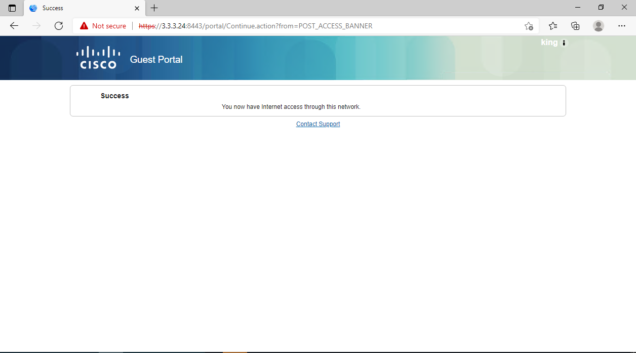
2. Verify that you can successfully pass portal authentication.
Figure 84 Passing authentication
3. On the switch, use the display mac-authentication connection command to display information about online MAC authentication users, including authorization information.
Figure 85 Viewing information about online MAC authentication users
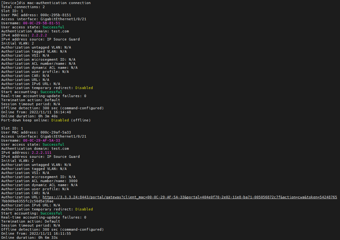
The output shows that the user in this example (with username 00-0C-29-AF-5A-33) has passed MAC authentication before portal authentication on the CWA page. Authorization URL and ACL 3000 have been assigned to the user.
4. View logs on the ISE server to verify that the authorization information has been authorized to the user.
Figure 86 Viewing logs on the ISE server
![]()
The ISE logs show that authorization CWA-redirect-hhh has been assigned to the user after the MAC authentication failed, and authorization PermitAccess has been assigned to the user after successful COA reauthentication (portal authentication) on the COA page.
Configuration files
#
mac-authentication domain test.com
mac-authentication user-name-format mac-address with-hyphen uppercase
#
#
vlan 2
description toClients
arp snooping enable
#
vlan 3
description toAAAserver
#
interface Vlan-interface2
description toClients
ip address 2.2.2.29 255.255.255.0
#
interface Vlan-interface3
description toAAAservers
ip address 3.3.3.29 255.255.255.0
#
interface GigabitEthernet1/0/2
port link-mode bridge
port access vlan 3
#
interface GigabitEthernet1/0/3
port link-mode bridge
port access vlan 2
MAC-authentication
#
radius scheme ise
primary authentication 3.3.3.24 key cipher $c$3$2oLOvHdRilTBlb6n1yh3/MoXN8z/RMbctQ==
primary accounting 3.3.3.24 key cipher $c$3$fAhWH/rHm9hCcPq2PBWQa54YG9xKuQ1P0w==
user-name-format keep-original
#
#
domain test.com
authentication default radius-scheme ise
authorization default radius-scheme ise
accounting default radius-scheme ise
#
Example: Configuring 802.1X or MAC authentication with VLAN assignment
Network configuration
As shown in Figure 87, configure the switch to work in conjunction with the Cisco ISE server to perform 802.1X or MAC authentication for the client. The client must pass 802.1X or MAC authentication to access network resources.
Configure the switch as follows:
· Use the Cisco ISE server as the RADIUS server to perform 802.1X or MAC authentication for the client.
· Configure the Cisco ISE server to assign authorization VLAN 2 to the client after the client passes 802.1X or MAC authentication. The initial VLAN is 144.

Hardware and software versions used
This configuration example was created and verified on the following hardware and software versions:
|
Hardware |
Software version |
|
Switch (S5560X) |
R6618P27 |
|
Authentication server |
Cisco ISE V2.4.0.357 patch 8 |
|
Client operating system |
Windows 10 21H2 |
|
Authentication client |
iNode PC 7.3 (E513) |
Procedures
Prerequisites
This example provides only the configuration for authentication. Make sure that the client, switch, and server have network connectivity to communicate with one another.
Configuring the switch
For MAC authentication users, configure the switch as described in "Configuring the switch."
For 802.1X authentication users, configure the switch as described in "Configuring the switch."
To verify the configuration, you can configure the DHCP server.
Configuring the Cisco ISE server
Configure basic settings:
· Configure the Cisco ISE server for MAC authentication users as described in "Configuring the ISE server."
· Configure the Cisco ISE server for 802.1X users as described in "Configuring the ISE server."
For VLAN assignment, you must configure the following settings on the ISE server:
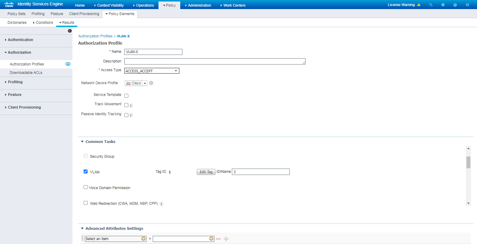
1. Configure an authorization profile:
# Navigate to the Policy > Policy Elements > Results > Authorization > Authorization Profiles page.
# Click Add to add an authorization profile.
# In the Authorization Profile area, set the name to VLAN-X, select network device profile Cisco in the Network Device Profile field.
# In the Common Tasks area, select VLAN, and enter an ACL number in the ID/Name field. In this example, 2 is used.
Figure 88 Configuring an authorization VLAN
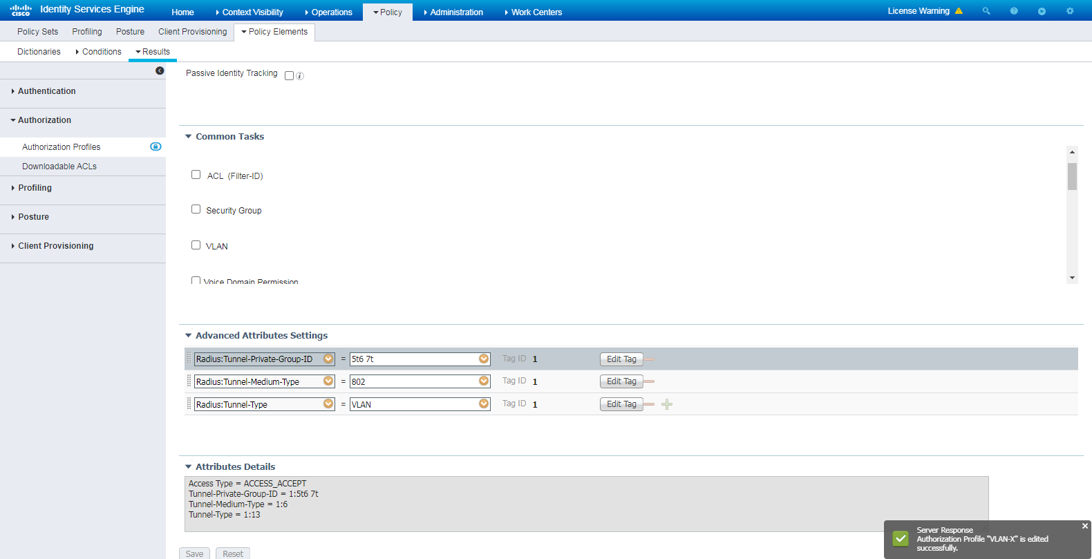
# To authorize VLAN information containing spaces in the attribute value, specify the attributes and attribute values in the Advanced Attributes Settings area as needed. If you enter the VLAN attribute value in the ID/Name field, the system prompts error message. For more information about VLAN attributes and values settings, see related product documents. In this example, VLAN 2 is used.
Figure 89 Configuring the Advanced Attributes Settings
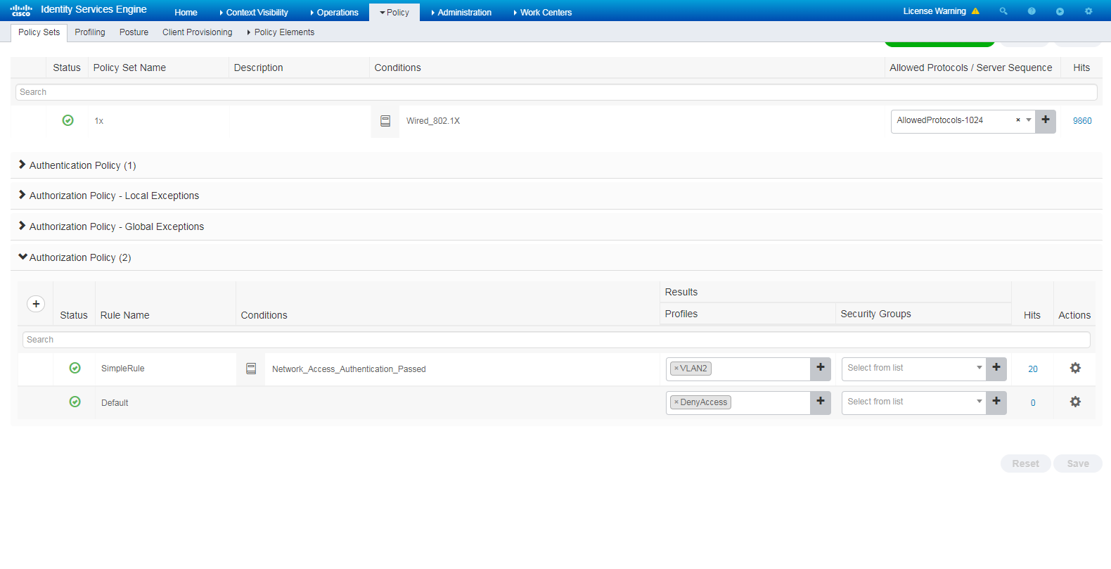
2. Configure a policy set:
# Navigate to the Policy > Policy Sets page.
# Click the + icon to add a policy set, as shown in Figure 90.
# Click the + icon in the Authorization Policy area, add an authorization policy named SimpleRule. In the Results > Profiles column for the authorization policy, select profile VLAN2.
Figure 90 Configuring a policy set
Verifying the configuration
Verify that VLAN 2 is successfully assigned to the authentication user. The following takes 802.1X authentication as an example.
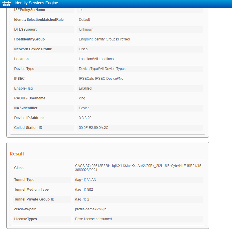
1. On the ISE server, navigate to the Operations > RADIUS page, and view live log information and live session information about the online user.
Figure 91 Viewing live log information for the user
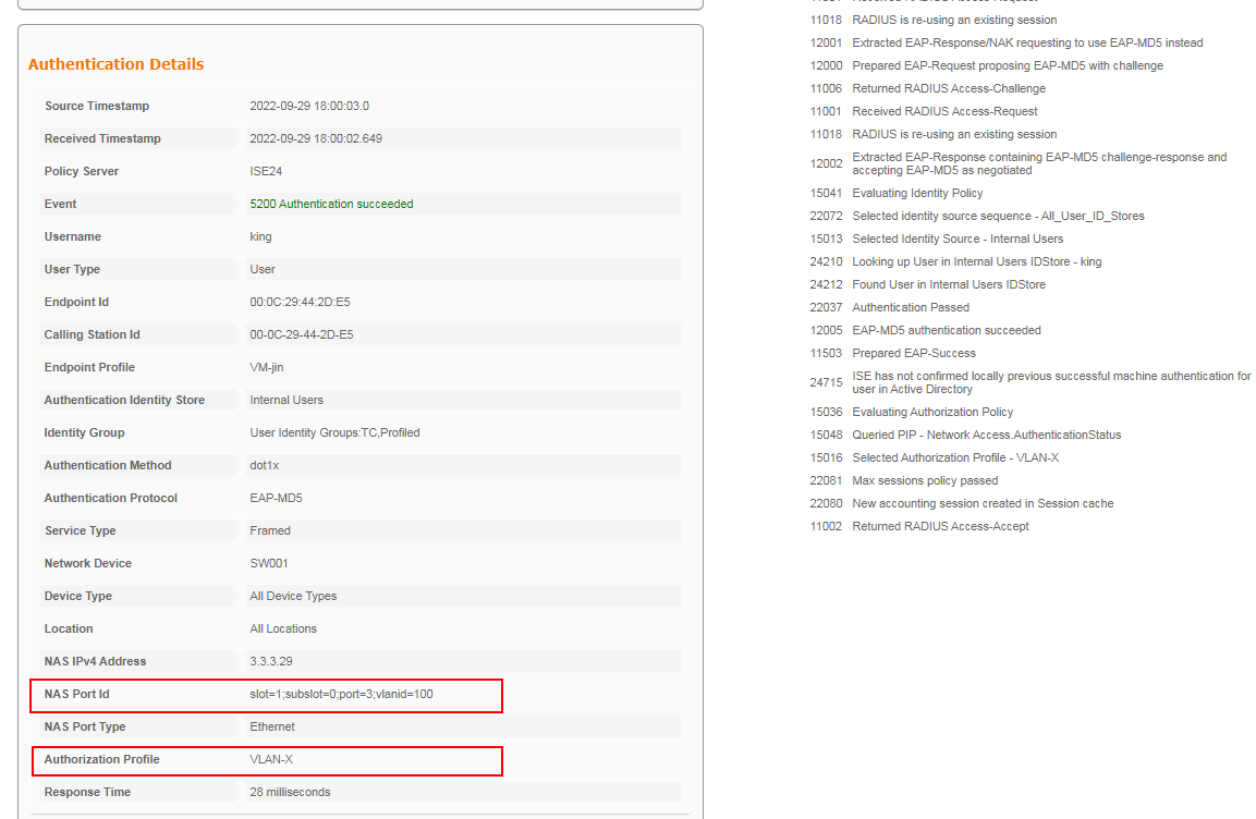
Figure 92 Viewing live log information for the user
2. On the switch, use the display dot1x connection command to display information about online 802.1 authentication users.
<Switch> display dot1x connection
Total connections: 1
Slot ID: 1
User MAC address: 000c-2944-2de5
Access interface: GigabitEthernet1/0/3
Username: king
User access state: Successful
Authentication domain: test.com
IPv4 address: 2.2.2.18
IPv4 address source: IP Source Guard
EAP packet identifier: 108
Authentication method: EAP
AAA authentication method: RADIUS
Initial VLAN: 100
Authorization untagged VLAN: 2
Authorization tagged VLAN list: N/A
Authorization VSI: N/A
Authorization microsegment ID: N/A
Authorization ACL number/name: N/A
Authorization dynamic ACL name: N/A
Authorization user profile: N/A
Authorization CAR: N/A
Authorization URL: N/A
Authorization IPv6 URL: N/A
Authorization temporary redirect: Disabled
Start accounting: Successful
Real-time accounting-update failures: 0
Termination action: Default
Session timeout period: N/A
Online from: 2022/09/29 17:58:14
Online duration: 0h 4m 6s
The output shows that VLAN 2 has been successfully assigned to the user.
3. Verify the connectivity:
# Verify that the client is added to VLAN 2 and an IP address is assigned to the user by the DHCP server.
Ethernet adapter AAAuser:
Connection-specific DNS Suffix :
Description : Intel(R) 82574L Gigabit Network Connection
Physical Address : 00-0C-29-44-2D-E5
DHCP Enabled : Yes
Autoconfiguration Enabled : Yes
IPv4 Address : 2.2.2.18(Preferred)
Subnet Mask : 255.255.255.0
Lease Obtained : 30 September 2022 17:00:41
Lease Expires : 10 October 2022 17:00:40
Default Gateway : 2.2.2.29
DHCP Server : 2.2.2.29
DNS Servers : 3.3.3.12
NetBIOS over Tcpip : Enabled
# Trace the path to destination (3.3.3.24) on the client to verify the connectivity of the client.
PS C:\Windows\system32> tracert 3.3.3.24
Tracing route to 3.3.3.24 over a maximum of 30 hops
1 1 ms 1 ms 1 ms 2.2.2.29
2 1 ms <1 ms <1 ms 3.3.3.24
Configuration files
The following takes 802.1X authentication as an example.
#
dot1x
dot1x authentication-method eap
#
vlan 1
#
vlan 2
description toClients
arp snooping enable
#
vlan 3
description toAAAserver
#
interface Vlan-interface1
#
interface Vlan-interface2
description toClients
ip address 2.2.2.29 255.255.255.0
#
interface Vlan-interface3
description toAAAservers
ip address 3.3.3.29 255.255.255.0
#
interface GigabitEthernet1/0/2
port link-mode bridge
port access vlan 3
#
interface GigabitEthernet1/0/3
port link-mode bridge
port access vlan 2
dot1x
#
radius scheme ise
primary authentication 3.3.3.24 key cipher $c$3$2oLOvHdRilTBlb6n1yh3/MoXN8z/RMbctQ==
primary accounting 3.3.3.24 key cipher $c$3$fAhWH/rHm9hCcPq2PBWQa54YG9xKuQ1P0w==
timer realtime-accounting 20 second
user-name-format keep-original
#
#
domain test.com
authentication default radius-scheme ise
authorization default radius-scheme ise
accounting default radius-scheme ise
#
dhcp enable
dhcp server forbidden-ip 2.2.2.29
#
dhcp server ip-pool Pool1
gateway-list 2.2.2.29
network 2.2.2.0 mask 255.255.255.0
dns-list 3.3.3.12
expired day 10
#
Examples: Configuring 802.1X, MAC, or portal authentication with static ACL assignment
Network configuration
As shown in Figure 93 configure the switch to work in conjunction with the Cisco ISE server to perform 802.1X, MAC, or portal authentication for the client. The client must pass authentication to access network resources.
Use the Cisco ISE server as a RADIUS server, and configure the Cisco ISE server to assign a static ACL to the client after the client passes authentication.

Hardware and software versions used
This configuration example was created and verified on the following hardware and software versions:
|
Hardware |
Software version |
|
Switch (S5560X) |
R6618P27 |
|
Authentication server |
Cisco ISE V2.4.0.357 patch 8 |
|
Client operating system |
Windows 10 21H2 |
|
Authentication client |
iNode PC 7.3 (E513) |
Configuring the switch
# (For MAC authentication users.) Configure MAC authentication (see "Configuring the switch").
# (For 802.1X users.) Configure 802.1X authentication (see "Configuring the switch").
# (For portal users.) Configure portal authentication (see "Configuring the switch").
# Create an ACL, and configure a rule.
[Switch] acl advanced 3200
[Switch-acl-ipv4-adv-3200] rule 0 deny ip destination 3.3.3.12 0
Configuring the ISE server
1. (For MAC authentication users.) Configure MAC authentication (see "Configuring the ISE server").
2. (For 802.1X users.) Configure 802.1X authentication (see "Configuring the ISE server").
3. (For portal users.) Configure portal authentication (see "Configuring the ISE server").
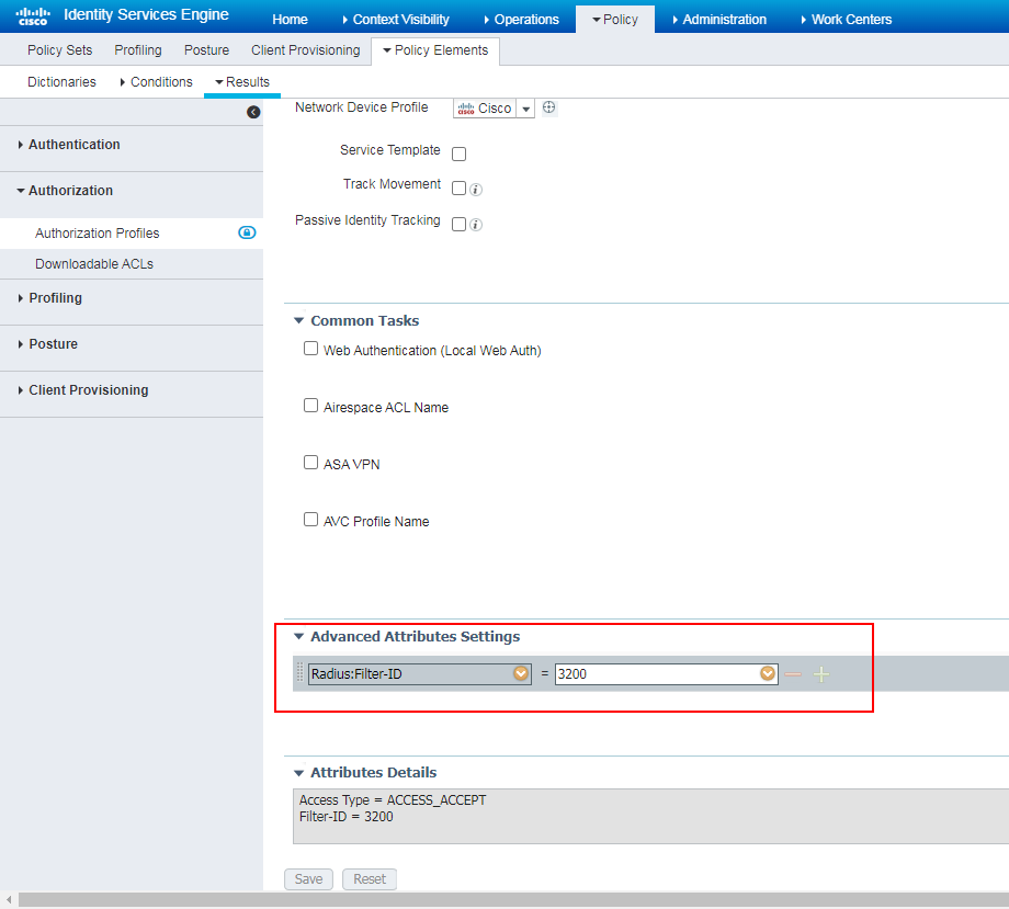
4. Configure an authorization profile:
# Navigate to the Policy > Policy Elements > Results > Authorization > Authorization Profiles page.
# Click Add to add an authorization profile.
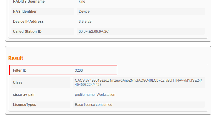
# In the Authorization Profile area, enter Static_ACL ID in the Name field, and select Cisco from the Network Device Profile list.
# In the Advanced Attributes Settings area, enter a Filter-ID of 3200.
Figure 94 Configuring an authorization profile
|
|
NOTE: If a Filter-ID contains only digits, it is treated as an ACL number. If a Filter-ID does not contain only digits, it is treated as a user profile. |
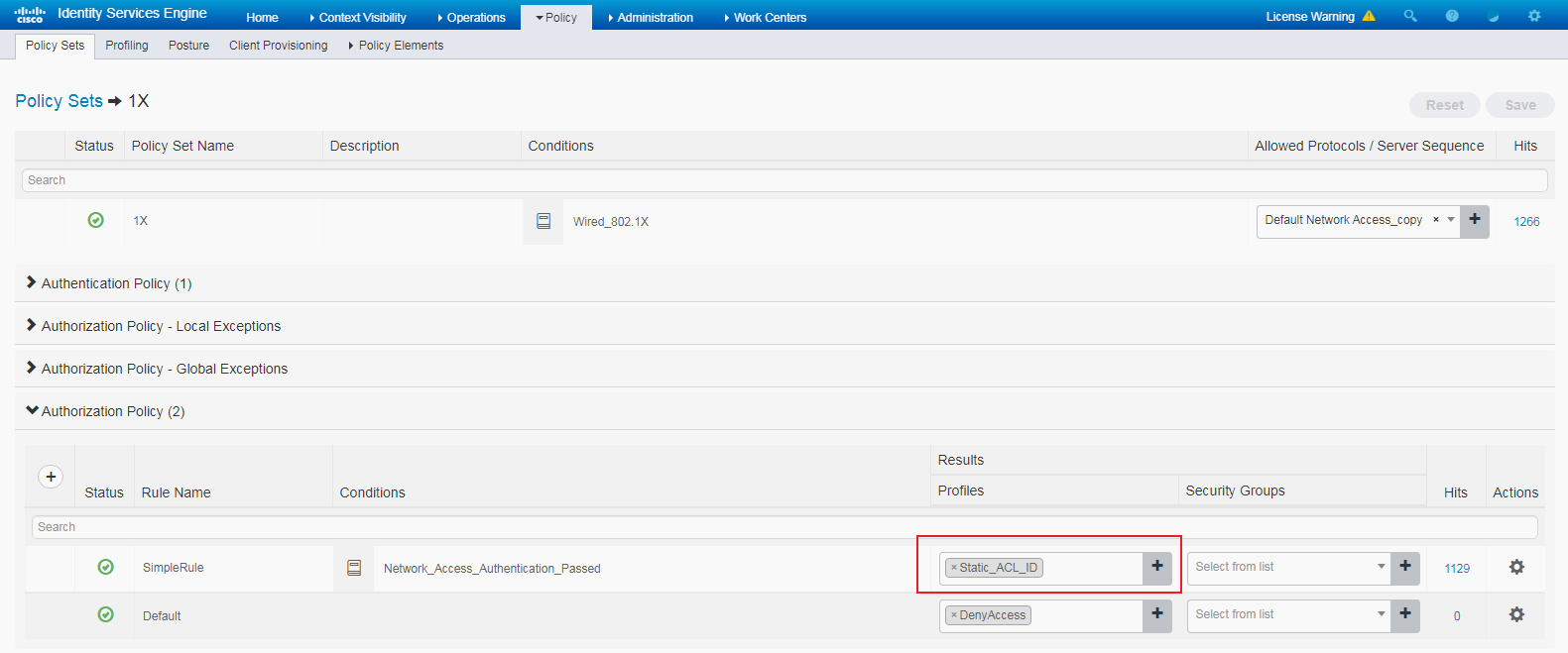
5. Configure a policy set:
# Navigate to the Policy > Policy Sets page
# Click the + icon to add a policy set, as shown in Figure 95.
# Click the + icon in the Authorization Policy area, and add an authorization policy named SimpleRule. In the Results > Profiles column for the authorization policy, select profile Static_ACL ID.
Figure 95 Configuring a policy set
Verifying the configuration
1. Verify that the static ACL has been successfully assigned to the authentication user.
# The following is the display on the ISE server:
# On the switch, use the display dot1x connection command to display information about online 802.1X users.
<Switch> display dot1x connection
Total connections: 1
Slot ID: 1
User MAC address: 000c-2944-2de5
Access interface: GigabitEthernet1/0/3
Username: king
User access state: Successful
Authentication domain: test.com
IPv4 address: 2.2.2.1
IPv4 address source: IP Source Guard
EAP packet identifier: 100
Authentication method: EAP
AAA authentication method: RADIUS
Initial VLAN: 2
Authorization untagged VLAN: N/A
Authorization tagged VLAN list: N/A
Authorization VSI: N/A
Authorization microsegment ID: N/A
Authorization ACL number/name: 3200
Authorization dynamic ACL name: N/A
Authorization user profile: N/A
Authorization CAR: N/A
Authorization URL: N/A
Authorization IPv6 URL: N/A
Authorization temporary redirect: Disabled
Start accounting: Successful
Real-time accounting-update failures: 0
Termination action: Default
Session timeout period: N/A
Online from: 2021/01/08 16:21:32
Online duration: 0h 6m 51s
The display shows that the static ACL has been successfully assigned to the user.
Configuration files
#
dot1x
dot1x authentication-method eap
#
vlan 1
#
vlan 2
description toClients
arp snooping enable
#
vlan 3
description toAAAserver
#
interface Vlan-interface1
#
interface Vlan-interface2
description toClients
ip address 2.2.2.29 255.255.255.0
#
interface Vlan-interface3
description toAAAservers
ip address 3.3.3.29 255.255.255.0
#
interface GigabitEthernet1/0/2
port link-mode bridge
port access vlan 3
#
interface GigabitEthernet1/0/3
port link-mode bridge
port access vlan 2
dot1x
#
radius scheme ise
primary authentication 3.3.3.24 key cipher $c$3$2oLOvHdRilTBlb6n1yh3/MoXN8z/RMbctQ==
primary accounting 3.3.3.24 key cipher $c$3$fAhWH/rHm9hCcPq2PBWQa54YG9xKuQ1P0w==
timer realtime-accounting 20 second
user-name-format keep-original
#
#
domain test.com
authentication default radius-scheme ise
authorization default radius-scheme ise
accounting default radius-scheme ise
#
Examples: Configuring 802.1X, MAC, or portal authentication with dynamic ACL assignment
Network configuration
As shown in Figure 96, configure the switch to work in conjunction with the Cisco ISE server to perform 802.1X authentication for the client. The client must pass 802.1X authentication to access network resources.
Use the Cisco ISE server as a RADIUS server, and configure the Cisco ISE server to assign a static dynamic ACL to the client after the client passes authentication.

Hardware and software versions used
This configuration example was created and verified on the following hardware and software versions:
|
Hardware |
Software version |
|
Switch (S5560X) |
R6618P27 |
|
Authentication server |
Cisco ISE V2.4.0.357 patch 8 |
|
Client operating system |
Windows 10 21H2 |
|
Authentication client |
iNode PC 7.3 (E513) |
Configuring the switch
# (For MAC authentication users.) Configure MAC authentication (see "Configuring the switch").
# (For 802.1X users.) Configure 802.1X authentication (see "Configuring the switch").
# (For portal users.) Configure portal authentication (see "Configuring the switch").
Configuring the ISE server
1. (For MAC authentication users.) Configure MAC authentication (see "Configuring the ISE server").
2. (For 802.1X users.) Configure 802.1X authentication (see "Configuring the ISE server").
3. (For portal users.) Configure portal authentication (see "Configuring the ISE server").
4. Configure an authorization profile:
# Navigate to the Policy > Policy Elements > Results > Authorization > Authorization Profiles page.
# Click Add to add an authorization profile.
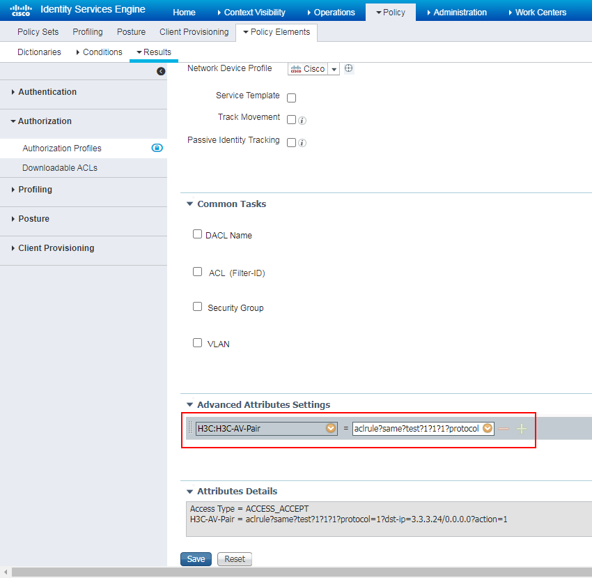
# In the Authorization Profile area, enter Dynamic_ACL in the Name field, and select Cisco from the Network Device Profile list.
# In the Advanced Attributes Settings area, Add H3C-AV-Pair and enter aclrule?same?test?1?1?1?protocol=1?dst-ip=3.3.3.24/0.0.0.0?action=1. For information about the ACL format, see related product documents.
Figure 97 Configuring an authorization profile
5. Configure a policy set:
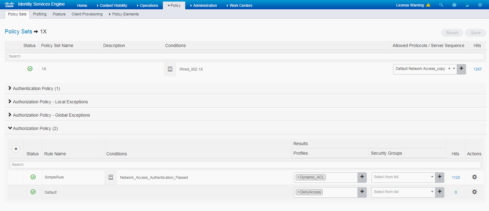
# Navigate to the Policy > Policy Sets page.
# Click the + icon to add a policy set, as shown in Figure 98.
# Click the + icon in the Authorization Policy area, and add an authorization policy named SimpleRule. In the Results > Profiles column for the authorization policy, select profile Dynamic_ACL.
Figure 98 Configuring a policy set
Verifying the configuration
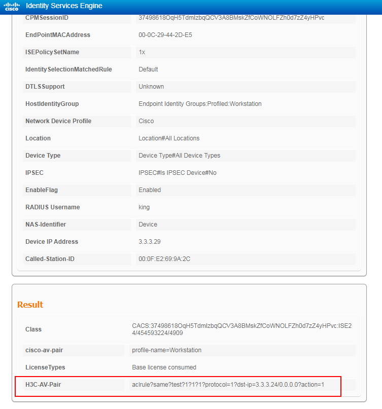
1. Verify that the dynamic ACL has been successfully assigned to the authentication user.
# The following is the display on the ISE server:
# On the switch, use the display dot1x connection command to display information about online 802.1X users.
<Switch> display dot1x connection
Total connections: 1
Slot ID: 1
User MAC address: 000c-2944-2de5
Access interface: GigabitEthernet1/0/3
Username: king
User access state: Successful
Authentication domain: test.com
IPv4 address: 2.2.2.1
IPv4 address source: IP Source Guard
EAP packet identifier: 217
Authentication method: EAP
AAA authentication method: RADIUS
Initial VLAN: 2
Authorization untagged VLAN: N/A
Authorization tagged VLAN list: N/A
Authorization VSI: N/A
Authorization microsegment ID: N/A
Authorization ACL number/name: N/A
Authorization dynamic ACL name: test
Authorization user profile: N/A
Authorization CAR: N/A
Authorization URL: N/A
Authorization IPv6 URL: N/A
Authorization temporary redirect: Disabled
Start accounting: Successful
Real-time accounting-update failures: 0
Termination action: Default
Session timeout period: N/A
Online from: 2021/01/08 18:59:52
Online duration: 0h 7m 56s
<Switch> display acl name test
Advanced IPv4 ACL named test, 1 rule,
This is a dynamic advanced IPv4 ACL
ACL's step is 5, start ID is 0
rule 1 deny ip destination 3.3.3.24 0 (Dynamic)
The display shows that the dynamic ACL has been successfully assigned to the user.
Configuration files
#
dot1x
dot1x authentication-method eap
#
vlan 1
#
vlan 2
description toClients
arp snooping enable
#
vlan 3
description toAAAserver
#
interface Vlan-interface1
#
interface Vlan-interface2
description toClients
ip address 2.2.2.29 255.255.255.0
#
interface Vlan-interface3
description toAAAservers
ip address 3.3.3.29 255.255.255.0
#
interface GigabitEthernet1/0/2
port link-mode bridge
port access vlan 3
#
interface GigabitEthernet1/0/3
port link-mode bridge
port access vlan 2
dot1x
#
radius scheme ise
primary authentication 3.3.3.24 key cipher $c$3$2oLOvHdRilTBlb6n1yh3/MoXN8z/RMbctQ==
primary accounting 3.3.3.24 key cipher $c$3$fAhWH/rHm9hCcPq2PBWQa54YG9xKuQ1P0w==
timer realtime-accounting 20 second
user-name-format keep-original
#
#
domain test.com
authentication default radius-scheme ise
authorization default radius-scheme ise
accounting default radius-scheme ise
#
Examples: Configuring 802.1X or MAC authentication with CAR setting assignment
Network configuration
As shown in Figure 99, configure the switch to work in conjunction with the Cisco ISE server to perform 802.1X or MAC authentication for the client. The client must pass authentication to access network resources.
Use the Cisco ISE server as a RADIUS server, and configure the Cisco ISE server to assign CAR settings to the client after the client passes authentication (average input rate, peak input rate, average output rate, and peak output rate).

Hardware and software versions used
This configuration example was created and verified on the following hardware and software versions:
|
Hardware |
Software version |
|
Switch (S5560X) |
R6618P27 |
|
Authentication server |
Cisco ISE V2.4.0.357 patch 8 |
|
Client operating system |
Windows 10 21H2 |
|
Authentication client |
iNode PC 7.3 (E513) |
Configuring the switch
# (For MAC authentication users.) Configure MAC authentication (see "Configuring the switch").
# (For 802.1X users.) Configure 802.1X authentication (see "Configuring the switch").
Configuring the ISE server
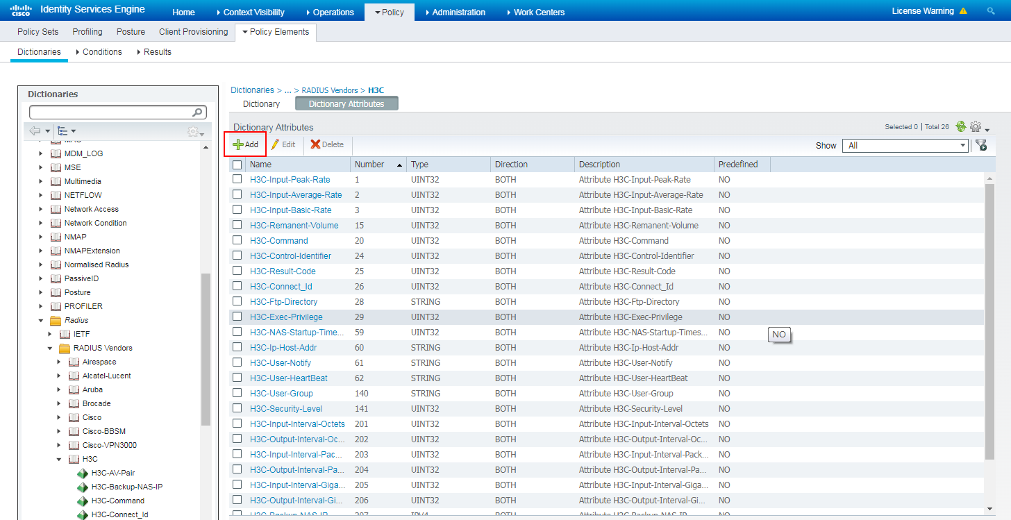
1. Add a dictionary attribute:
# Navigate to the Policy > Policy Elements > Dictionaries > RADIUS Vendors > H3C page.
# Click Add to add a dictionary attribute.
Figure 100 Adding a dictionary attribute
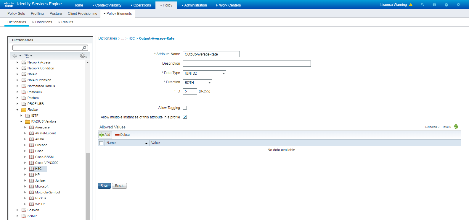
# Enter Output-Average-Rate in the Attribute Name field, and select UINT32 from the Data Type list.
Figure 101 Configuring Output-Average-Rate
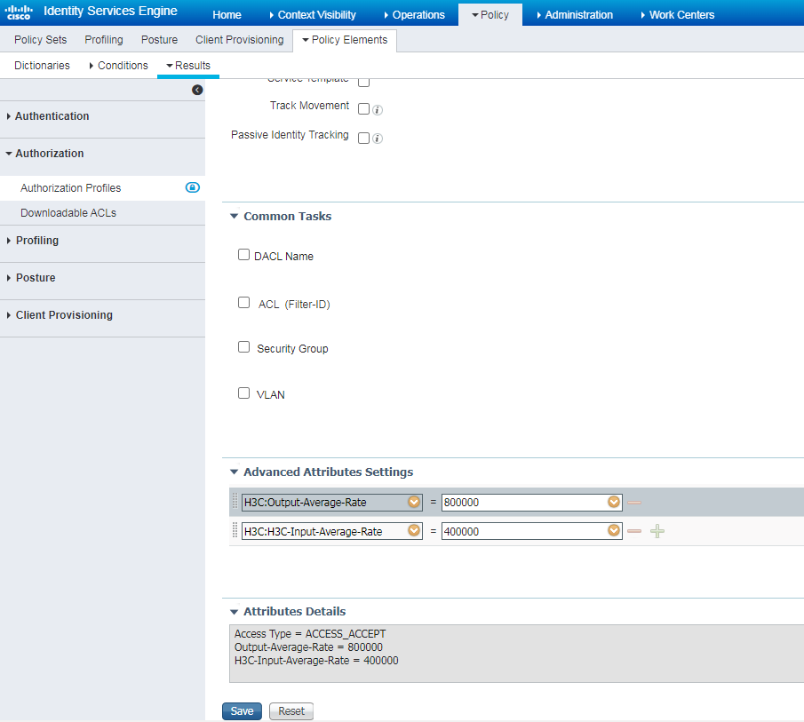
# Create an authorization profile named QoS, select H3C-Out-Average-Rate and H3C-H3C-Input-Average-Rate in the area, and enter values.
Figure 102 Configuring an authorization profile
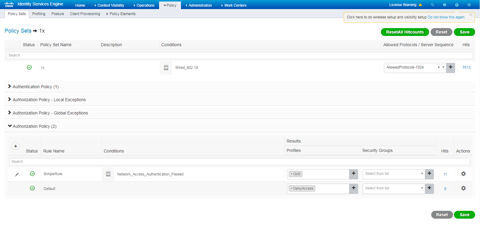
# Select authorization profile QoS in the authorization policy.
Figure 103 Configuring an authorization policy
Verifying the configuration
1. Verify that CAR settings have been successfully assigned to the authentication user.
The following is the display on the ISE server:
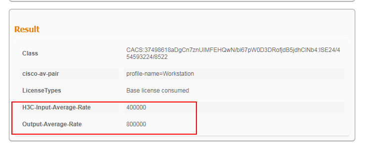
# On the switch, use the display dot1x connection command to display information about online 802.1X users.
<Switch> display dot1x connection
Total connections: 1
Slot ID: 1
User MAC address: 000c-2944-2de5
Access interface: GigabitEthernet1/0/3
Username: king
User access state: Successful
Authentication domain: test.com
IPv4 address: 2.2.2.1
IPv4 address source: IP Source Guard
EAP packet identifier: 16
Authentication method: EAP
AAA authentication method: RADIUS
Initial VLAN: 2
Authorization untagged VLAN: N/A
Authorization tagged VLAN list: N/A
Authorization VSI: N/A
Authorization microsegment ID: N/A
Authorization ACL number/name: N/A
Authorization dynamic ACL name: N/A
Authorization user profile: N/A
Authorization CAR:
Average input rate: 400000 bps
Peak input rate: 400000 bps
Average output rate: 800000 bps
Peak output rate: 800000 bps
Authorization URL: N/A
Authorization IPv6 URL: N/A
Authorization temporary redirect: Disabled
Start accounting: Successful
Real-time accounting-update failures: 0
Termination action: Default
Session timeout period: N/A
Online from: 2021/01/09 14:24:42
Online duration: 1h 8m 46s
The display shows that the CAR settings have been successfully assigned to the user.
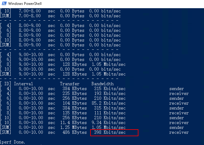
# Use a Windows 10 terminal and iperf to verity the input rate limiting. The input rate limiting result is as follows:
Configuration files
#
dot1x
dot1x authentication-method eap
#
vlan 1
#
vlan 2
description toClients
arp snooping enable
#
vlan 3
description toAAAserver
#
interface Vlan-interface1
#
interface Vlan-interface2
description toClients
ip address 2.2.2.29 255.255.255.0
#
interface Vlan-interface3
description toAAAservers
ip address 3.3.3.29 255.255.255.0
#
interface GigabitEthernet1/0/2
port link-mode bridge
port access vlan 3
#
interface GigabitEthernet1/0/3
port link-mode bridge
port access vlan 2
dot1x
#
radius scheme ise
primary authentication 3.3.3.24 key cipher $c$3$2oLOvHdRilTBlb6n1yh3/MoXN8z/RMbctQ==
primary accounting 3.3.3.24 key cipher $c$3$fAhWH/rHm9hCcPq2PBWQa54YG9xKuQ1P0w==
timer realtime-accounting 20 second
user-name-format keep-original
#
#
domain test.com
authentication default radius-scheme ise
authorization default radius-scheme ise
accounting default radius-scheme ise
#
Example: Configuring URL redirection
Network configuration
As shown in Figure 104, configure the switch to work in conjunction with the Cisco ISE server to perform 802.1X authentication for the client. The client must pass 802.1X authentication to access network resources.
Configure the devices as follows:
· Use the Cisco ISE server as the RADIUS server and portal server to perform 802.1X authentication for the client.
· Configure the ISE server to assign an authorization URL to the authenticated client, so when the user enters any IP address in the browser, the user is redirected to the authorization URL.

Hardware and software versions used
This configuration example was created and verified on the following hardware and software versions:
|
Hardware |
Software version |
|
Switch (S5560X) |
R6618P27 |
|
Authentication server |
Cisco ISE V2.4.0.357 patch 8 |
|
Client operating system |
Windows 10 21H2 |
|
Authentication client |
iNode PC 7.3 (E513) |
Procedures
Prerequisites
This example provides only the configuration for authentication. Make sure that the client, switch, and server have network connectivity to communicate with one another.
Configuring the switch
# Configure an ACL to permit the IP address for the authorization URL. The server needs to deploy the authorization URL.
[Switch] acl advanced 3300
[Switch-acl-ipv4-adv-3100] rule 1 permit ip destination 3.3.3.31 0
# Configure other settings as described in "Configuring the switch."
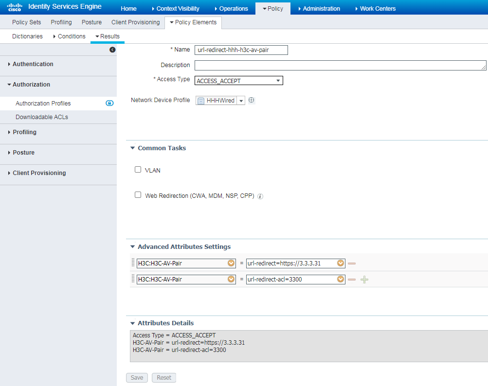
Configuring the ISE server
Configure the ISE server as described in "Configuring the ISE server," except that you must create an authorization profile as shown in Figure 105.
Figure 105 Creating an Authorization Profile
Verifying the configuration
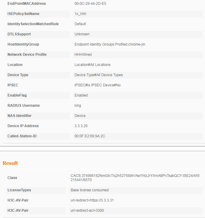
1. After the user comes online, view information about the online user on the ISE server.
Figure 106 Viewing user access information
2. On the switch, use the display dot1x connection command to display information about online 802.1X authentication users.
<Switch> display dot1x connection
Total connections: 1
Slot ID: 1
User MAC address: 000c-2944-2de5
Access interface: GigabitEthernet1/0/3
Username: king
User access state: Successful
Authentication domain: test.com
IPv4 address: 2.2.2.10
IPv4 address source: IP Source Guard
EAP packet identifier: 117
Authentication method: CHAP
AAA authentication method: RADIUS
Initial VLAN: 2
Authorization untagged VLAN: N/A
Authorization tagged VLAN list: N/A
Authorization VSI: N/A
Authorization microsegment ID: N/A
Authorization ACL number/name: 3300
Authorization dynamic ACL name: N/A
Authorization user profile: N/A
Authorization CAR: N/A
Authorization URL: https://3.3.3.31
Authorization IPv6 URL: N/A
Authorization temporary redirect: Disabled
Start accounting: Successful
Real-time accounting-update failures: 0
Termination action: Default
Session timeout period: N/A
Online from: 2022/10/18 14:40:26
Online duration: 1h 39m 14s
3. On the client, enter any IP address in the browser address bar. You will be redirected to the authorization URL.
Configuration files
#
dot1x
dot1x authentication-method eap
#
vlan 1
#
vlan 2
description toClients
arp snooping enable
#
vlan 3
description toAAAserver
#
interface Vlan-interface1
#
interface Vlan-interface2
description toClients
ip address 2.2.2.29 255.255.255.0
#
interface Vlan-interface3
description toAAAservers
ip address 3.3.3.29 255.255.255.0
#
interface GigabitEthernet1/0/2
port link-mode bridge
port access vlan 3
#
interface GigabitEthernet1/0/3
port link-mode bridge
port access vlan 2
dot1x
#
radius scheme ise
primary authentication 3.3.3.24 key cipher $c$3$2oLOvHdRilTBlb6n1yh3/MoXN8z/RMbctQ==
primary accounting 3.3.3.24 key cipher $c$3$fAhWH/rHm9hCcPq2PBWQa54YG9xKuQ1P0w==
timer realtime-accounting 20 second
user-name-format keep-original
#
#
domain test.com
authentication default radius-scheme ise
authorization default radius-scheme ise
accounting default radius-scheme ise
#
Example: Configuring DAE
Network configuration
As shown in Figure 107, configure the switch to work in conjunction with the Cisco ISE server to perform 802.1X authentication for the client. The client must pass 802.1X authentication to access network resources.
Configure the devices as follows:
· Use the Cisco ISE server as the RADIUS server to perform 802.1X authentication for the client.
· Use the Cisco ISE server to send DAE requests to the switch.

Hardware and software versions used
This configuration example was created and verified on the following hardware and software versions:
|
Hardware |
Software version |
|
Switch (S5560X) |
R6618P27 |
|
Authentication server |
Cisco ISE V2.4.0.357 patch 8 |
|
Client operating system |
Windows 10 21H2 |
|
Authentication client |
iNode PC 7.3 (E513) |
Configuring the switch
Configure the switch as described in "Configuring the switch."
Besides, add the following configurations for DAE:
# Enable the RADIUS DAS feature and enter RADIUS DAS view.
[Switch] radius dynamic-author server
# Specify the DAC as 3.3.3.24 (the IP address of the AAA server). Set the shared key to expert in plaintext form and use the default port 3799 for communication between the DAS and DAC. Make sure the shared key is the same as the shared secret configured on the ISE server.
[Switch-radius-da-server] client ip 3.3.3.24 key simple expert
[Switch-radius-da-server] quit
Configuring the ISE server
Configure the ISE server as described in "Configuring the ISE server."
Then, add the following configuration on the ISE server:
# Navigate to the Administration > Network Resources> Network Devices > Network Devices page.
# Confirm that the CoA Port of the device added to ISE is consistent with the DAE packet listening port used by the switch (the default port 3799 in this example).
Figure 108 Confirming the network device CoA Port
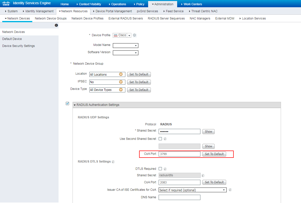
Verifying the configuration
Reauthentication
1. After the client comes online by using 802.1X PAP/CHAP authentication, trigger reauthentication on the ISE server:
# Log in to ISE, and then navigate to Operations > RADIUS > Live Sessions.
# In the Action column for the session, click the Show CoA Actions icon and then select Session reauthentication.
You can also select Session termination with port bounce, Session termination with port shutdown, Session termination to trigger other functions.
Figure 109 Selecting Session reauthentication
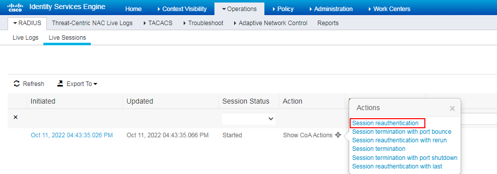
After you click Session reauthentication, the following tip is shown in the bottom right corner.
Figure 110 Tip for the session reauthentication action
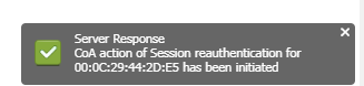
2. View logs on the ISE server:
Navigate to Operations > RADIUS > Live Logs. You can see that the dynamic authorization succeeded.
Figure 111 Live Logs
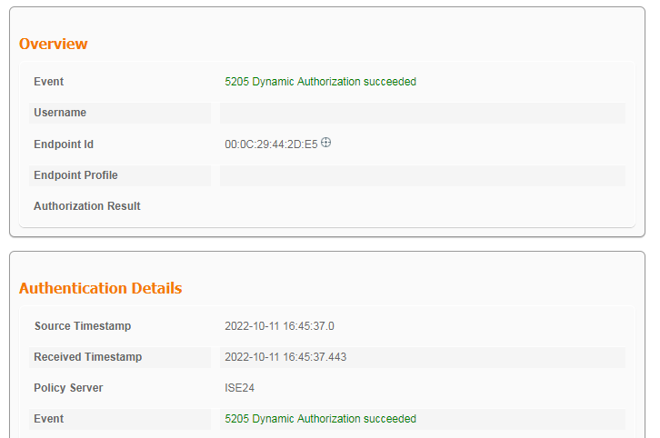
Configuration files
#
dot1x
dot1x authentication-method eap
#
vlan 1
#
vlan 2
description toClients
arp snooping enable
#
vlan 3
description toAAAserver
#
interface Vlan-interface1
#
interface Vlan-interface2
description toClients
ip address 2.2.2.29 255.255.255.0
#
interface Vlan-interface3
description toAAAservers
ip address 3.3.3.29 255.255.255.0
#
interface GigabitEthernet1/0/2
port link-mode bridge
port access vlan 3
#
interface GigabitEthernet1/0/3
port link-mode bridge
port access vlan 2
dot1x
#
radius scheme ise
primary authentication 3.3.3.24 key cipher $c$3$2oLOvHdRilTBlb6n1yh3/MoXN8z/RMbctQ==
primary accounting 3.3.3.24 key cipher $c$3$fAhWH/rHm9hCcPq2PBWQa54YG9xKuQ1P0w==
timer realtime-accounting 20 second
user-name-format keep-original
#
#
domain test.com
authentication default radius-scheme ise
authorization default radius-scheme ise
accounting default radius-scheme ise
Example: Configuring HWTACACS authentication for SSH login
Network configuration
As shown in Figure 112, a Cisco ISE is used as the RADIUS server. Configure remote HWTACACS authentication to authenticate the client when the client accesses the switch through SSH. Assign level-15 role to the client, and forbid level-15 users to execute the display cpu-usage command.
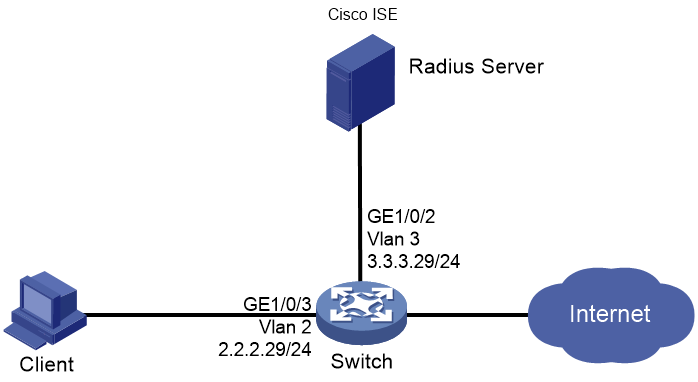
Hardware and software versions used
This configuration example was created and verified on the following hardware and software versions:
|
Hardware |
Software version |
|
Switch (S5560X) |
R6618P27 |
|
Authentication server |
Cisco ISE V2.4.0.357 patch 8 |
|
Client operating system |
Windows 10 21H2 |
|
Authentication client |
iNode PC 7.3 (E513) |
Procedure
Prerequisites
This example provides only the configuration for authentication. Make sure that the client, switch, and server have network connectivity to communicate with one another.
Configuring the switch
1. Configure an HWTACACS scheme:
# Create an HWTACACS scheme named ise and enter its view.
<Switch> system-view
[Switch] hwtacacs scheme ise
# Specify the IP address of the authorization, authentication, and accounting server as 3.3.3.24, and configure plaintext shared key expert for authorization, authentication, and accounting.
[Switch-hwtacacs-ise] primary authorization 3.3.3.24 key simple expert
[Switch-hwtacacs-ise] primary authentication 3.3.3.24 key simple expert
[Switch-hwtacacs-ise] primary accounting 3.3.3.24 key simple expert
# Configure the switch to send usernames in the original format to the RADIUS server. The usernames do not carry the ISP domain name.
[Switch-radius-ise] user-name-format keep-original
2. Configure the ISP domain:
# Create ISP domain ise, and apply HWTACACS scheme ise to the ISP domain for authentication, authorization, and accounting.
[Switch] domain ise
[Switch-isp-ise] authentication login hwtacacs-scheme ise
[Switch-isp-ise] authorization login hwtacacs-scheme ise
[Switch-isp-ise] accounting login none
[Switch-isp-ise] authorization command hwtacacs-scheme ise
[Switch-isp-ise] accounting command hwtacacs-scheme ise
[Switch-isp-ise] quit
# Configure domain ise as the default ISP domain. All access users use the authentication and accounting methods defined in the ISP domain if the usernames specified at user login do not contain ISP domain names.
[Switch] domain default enable ise
3. Configure SSH authentication:
# Generate local RSA key pairs.
[Switch] public-key local create rsa
The range of public key modulus is (512 ~ 4096).
If the key modulus is greater than 512, it will take a few minutes.
Press CTRL+C to abort.
Input the modulus length [default = 1024]:
Generating Keys...
...
Create the key pair successfully.
# Generate local DSA key pairs.
[Switch] public-key local create dsa
The range of public key modulus is (512 ~ 2048).
If the key modulus is greater than 512, it will take a few minutes.
Press CTRL+C to abort.
Input the modulus length [default = 1024]:
Generating Keys...
........
Create the key pair successfully.
# Enable SSH server.
[Switch] ssh server enable
# Specify the authentication mode as scheme, and enable command authorization and command accounting.
[Switch] line vty 0 63
[Switch-line-vty0-63] authentication-mode scheme
[Switch-line-vty0-63] command authorization
[Switch-line-vty0-63] command accounting
[Switch-line-vty0-63] quit
# Enable the default user role feature.
[Switch] role default-role enable
Configuring the ISE server
1. Create a user account:
Navigate to Administration > Identity Management > Identifies > Users. Click Add, set the username to king, and set the password to king.
Figure 113 Creating a user account

2. Add a switch:
Navigate to Work Centers > Device Administration > Network Resources > Network Devices. Click Add, specify the device name as 5560x, specify the IP address as 3.3.3.29, select TACACS Authentication Settings, and set the shared secret to expert.
Figure 114 Adding a switch
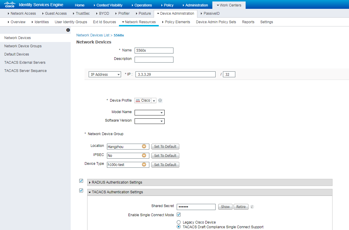
3. Configure authentication:
# Configure authentication protocols.
Navigate to Work Centers > Device Administration > Policy Elements > Results > Allowed Protocols. Confirm to use Default Switch Admin.
Figure 115 Configuring authentication protocols
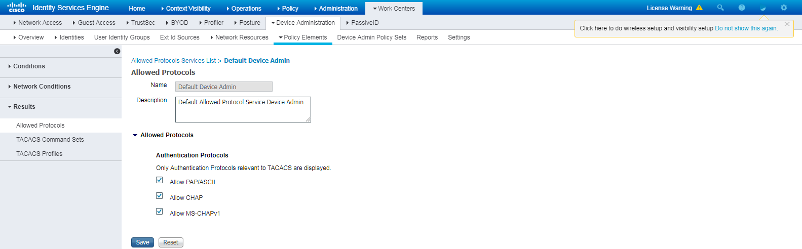
# Configure the TACACS authorized user role:
Navigate to Work Centers > Device Administration > Policy Elements > Results > TACACS Profiles. Click Add, specify the profile name as TACACSProfile1, and set the default privilege to level 15.
Figure 116 Configuring the authorized user role
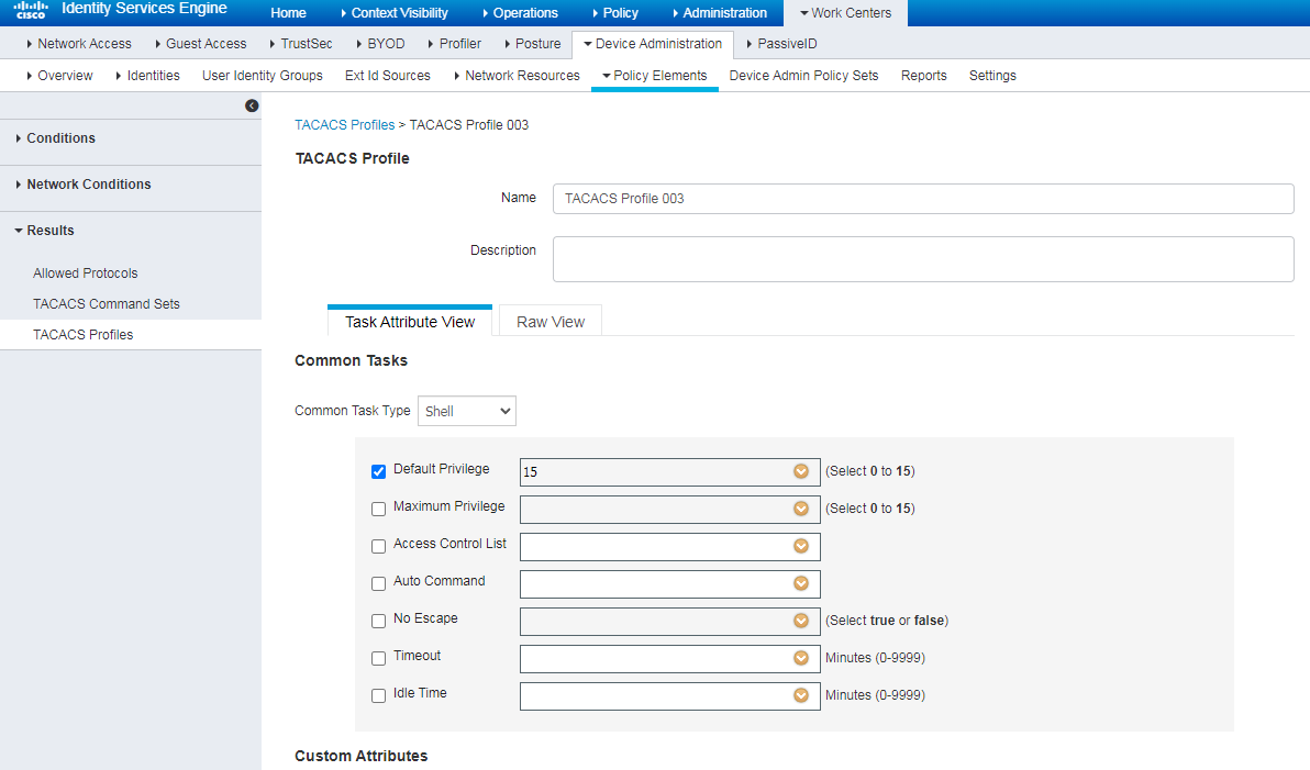
# Configure an authorized command set.
Navigate to Work Centers > Device Administration > Policy Elements > Results > TACACS Command Sets. Click Add, specify the command set name as CommandSet1, select Permit any command that is not listed below, and add command display cpu-usage to the list.
Figure 117 Configuring an authorized command set
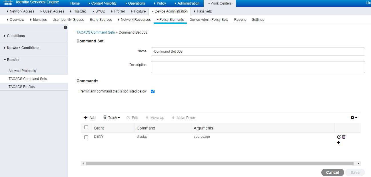
4. Configure the authentication and authorization policy set:
# Create an authentication policy.
Navigate to Work Centers > Device Administration > Device Admin Policy Sets, and then click the plus sign (+).
Figure 118 Creating an authentication policy
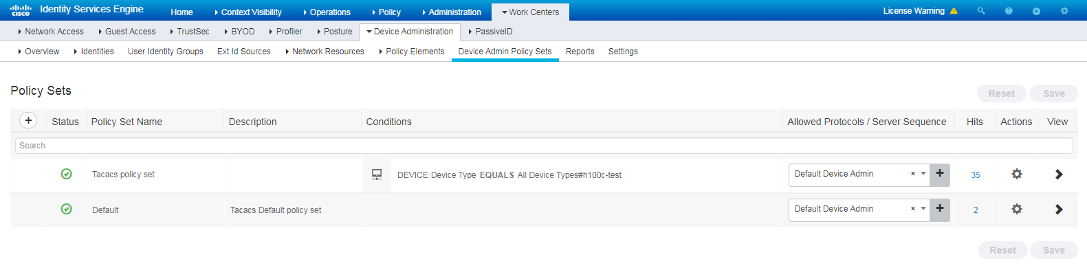
# Configure the authentication and authorization policy set.
Click the View icon for the newly created authentication policy. Create an authorization policy, and specify the TACACS role and TACACS command set to be authorized.
Figure 119 Configuring the authentication and authorization policy set
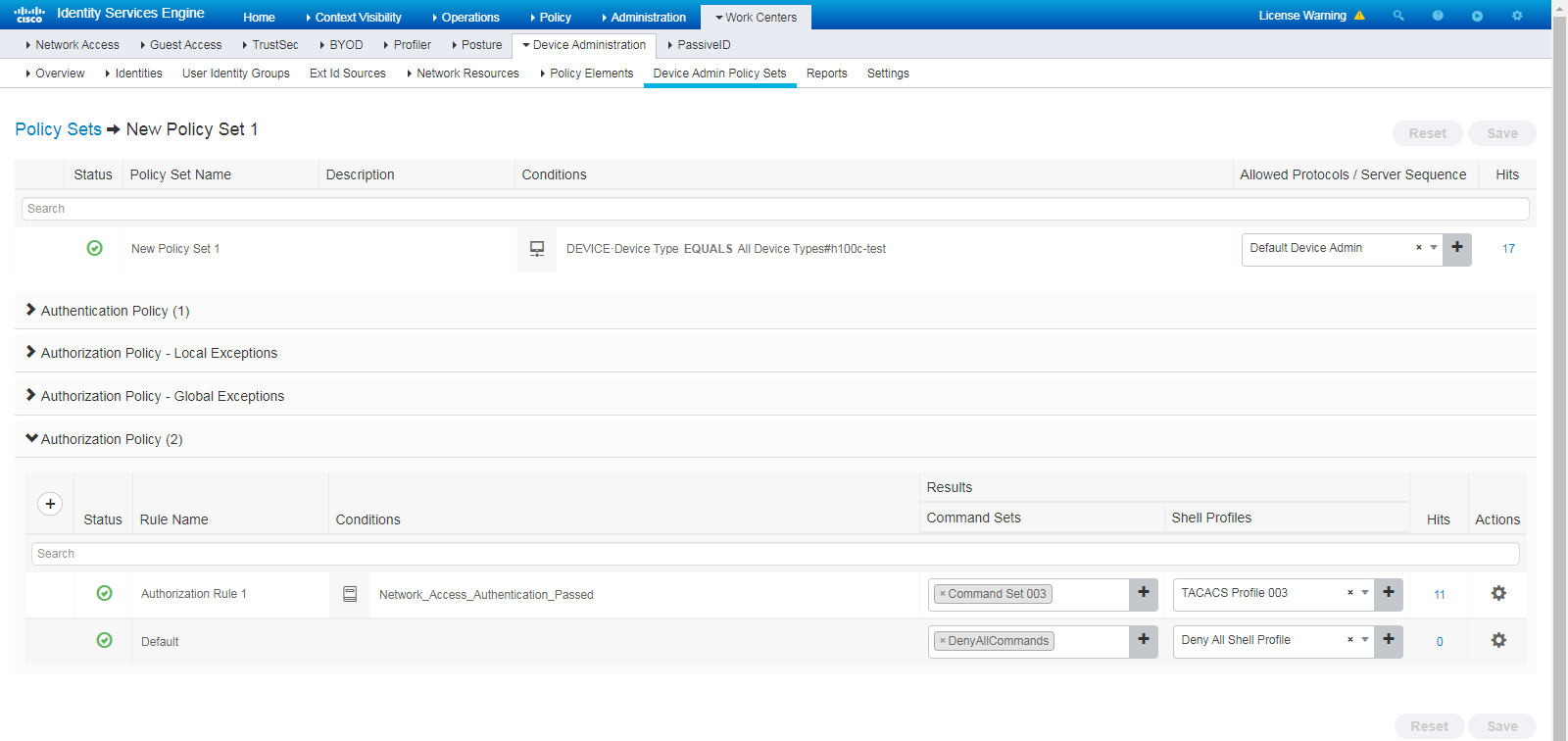
5. Enable device administration:
Navigate to Work Centers > Device Administration > Overview > Deployment, and select an option. Make sure the target node is selected.
Figure 120 Deployment page
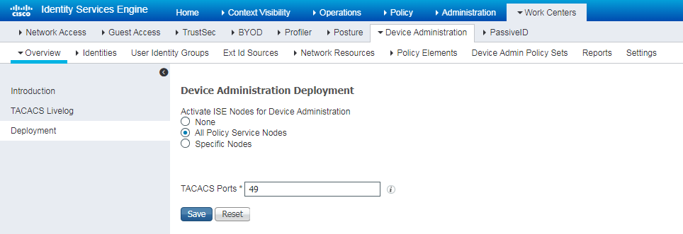
Verifying the configuration
Configuring the SSH client
|
|
NOTE: Various SSH software clients are available, such as PuTTY and OpenSSH. This section uses PuTTY0.76 as an example to illustrate the configuration method for the Stelnet client. |
# Install the PuTTY 0.76 software.
# Execute PuTTY.exe, and click the Session section.
· Enter the IP address of the SSH server in the Host Name or IP address field.
· Enter SSH protocol port number 22 in the Port field.
· Select the SSH protocol in the Connection type field.
# Click Open.
# If the system prompts a PuTTY security alert as shown in Figure 121, read the information, and click the corresponding button. In this example, the server is trusted and Yes is clicked.
Figure 121 PuTTY security alert (1)
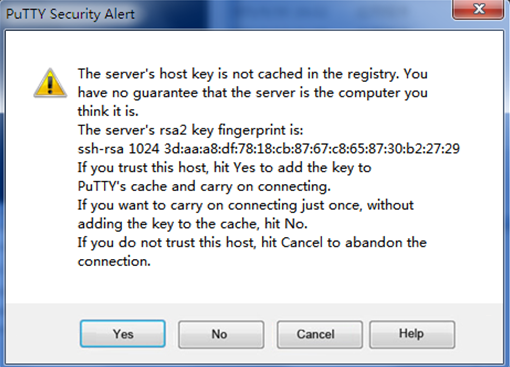
# If the system prompts a PuTTY security alert as shown in Figure 122, read the information, and click the corresponding button. In this example, the host key is trusted and Yes is clicked.
Figure 122 PuTTY security alert (2)
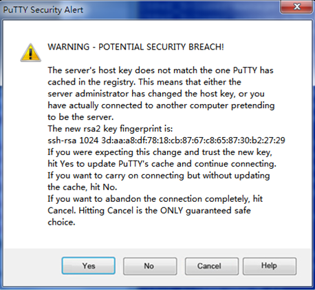
# Enter username king and password king on the login screen. Verify that you can log in successfully.
login as: king
king@55.73.134.29's password:
******************************************************************************
* Copyright (c) 2004-2021 New H3C Technologies Co., Ltd. All rights reserved.*
* Without the owner's prior written consent, *
* no decompiling or reverse-engineering shall be allowed. *
******************************************************************************
<Switch>
Verifying role and command authorization
# Verify that you can execute a command allowed for level-15 users, for example, the display memory command, and the display cpu-usage command cannot be executed.
[Switch]display memory
Memory statistics are measured in KB:
Slot 1:
Total Used Free Shared Buffers Cached FreeRatio
Mem: 2036432 785096 1251336 0 1472 258008 62.0%
-/+ Buffers/Cache: 525616 1510816
Swap: 0 0 0
LowMem: 1651408 400692 1250716 -- -- -- 75.7%
HighMem: 385024 384404 620 -- -- -- 0.2%
[Switch]display cpu-usage
Permission denied.
# Verify that the current user role is level-15.
[Switch]display users
Idx Line Idle Time Pid Type
+ 10 VTY 0 00:00:00 Oct 17 20:11:40 105288 SSH
Following are more details.
VTY 0 :
User name: king
User role list: level-15
Location: 55.73.134.88
Viewing server-end logs
Navigate to Work Centers > Device Administration > Overview > TACACS Livelog. Verify that you can view authentication-related logs.
Figure 123 TACACS Livelog
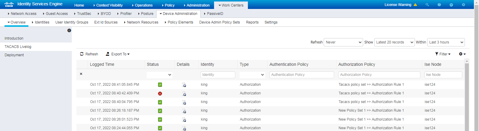
Figure 124 Execution denied for the display cpu-usage command
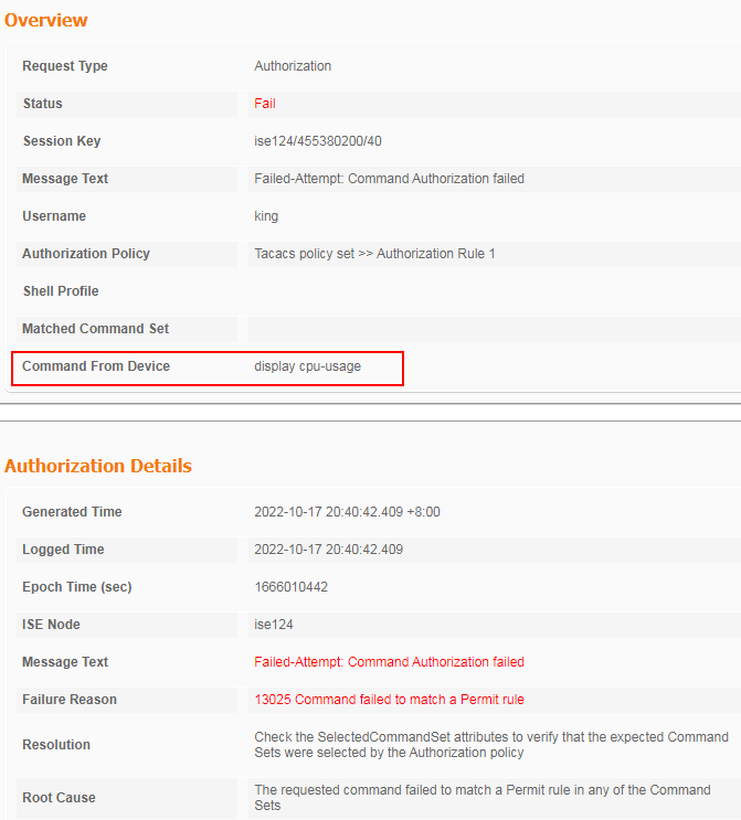
Figure 125 TACACS login success
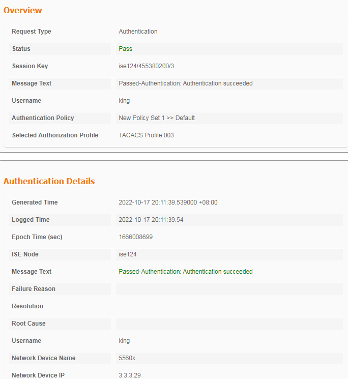
Configuration files
#
hwtacacs scheme ise
primary authentication 3.3.3.24 key cipher $c$3$wUwB4o8ka2I7ajzobLbwHsYtDKub7VhEdA==
primary authorization 3.3.3.24 key cipher $c$3$/Eh17X/LhZiOsed29CU4/fKGEtpwjCT6Pg==
primary accounting 3.3.3.24 key cipher $c$3$SkVBs/z9WNAvWzgTNx1mZSs0reEKR+7EOQ==
user-name-format without-domain
#
domain ise
authentication login hwtacacs-scheme ise
authorization login hwtacacs-scheme ise
accounting login none
authorization command hwtacacs-scheme ise
accounting command hwtacacs-scheme ise
#
public-key local create rsa
#
public-key local create dsa
#
ssh server enable
#
role default-role enable
#
line vty 0 31
authentication-mode scheme
command authorization
command accounting
#
Example: Configuring LDAP account collaboration with authentication
Network configuration
As shown in Figure 126, the Client, the ISE server, and the LDAP server (Windows Server) connect to each other through the switch. Configure 802.1X authentication to control client network access:
· Use Cisco ISE as the RADIUS server.
· Use a username and password set in the Windows Server for authentication.
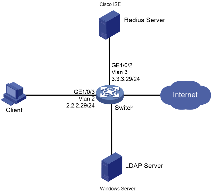
Hardware and software versions used
This configuration example was created and verified on the following hardware and software versions:
|
Hardware |
Software version |
|
Switch (S5560X) |
R6618P27 |
|
Authentication server |
Cisco ISE V2.4.0.357 patch 8 |
|
Client operating system |
Windows 10 21H2 |
|
Authentication client |
iNode PC 7.3 (E513) |
|
LDAP server |
Windows Server 2012R2 |
Procedure
Prerequisites
This example provides only the configuration for authentication. Make sure that the client, switch, and servers have network connectivity to communicate with one another.
Configuring the switch
# Specify the EAP authentication method as EAP. This example uses authentication method PEAP (EAP-GTC). For more information about other settings, see "Configuring the switch."
[Switch] dot1x authentication-method EAP
Configuring the ISE server
1. Create an external identity source:
Navigate to Administration > Identity Management > External Identity Sources > LDAP, click Add, and create an LDAP identity source named LDAP_Identity_Source456.
Figure 127 Creating an external identity source
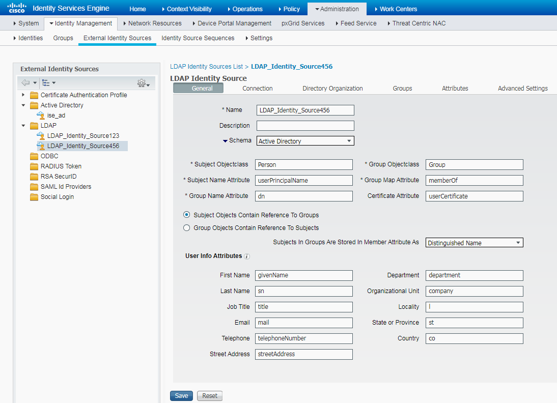
For security purposes, use the LDAPS method to connect to the LDAP server. On the Connection tab, specify the host name/IP of the LDAP server, specify the LDAPS port number as 636. If the LDAP method is used, the port number is 389. Obtain the other parameters from the LDAP server. For more information, see the related documents for the Windows Server.
Figure 128 Modifying parameters on the Connection tab
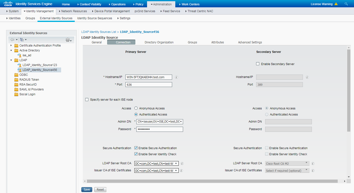
Click Test Bind to Server. Verify that a connection can be established successfully.
Figure 129 Connection success
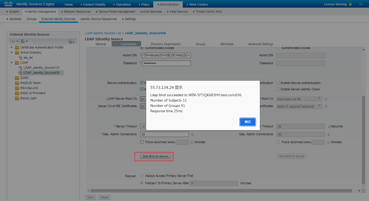
2. Configure authentication protocols:
Navigate to Policy > Policy Elements > Results > Authentication > Allowed Protocols, specify the name as 1x_EAP-PEAP-GTC, and select EAP-GTC.
Figure 130 Configuring authentication protocols
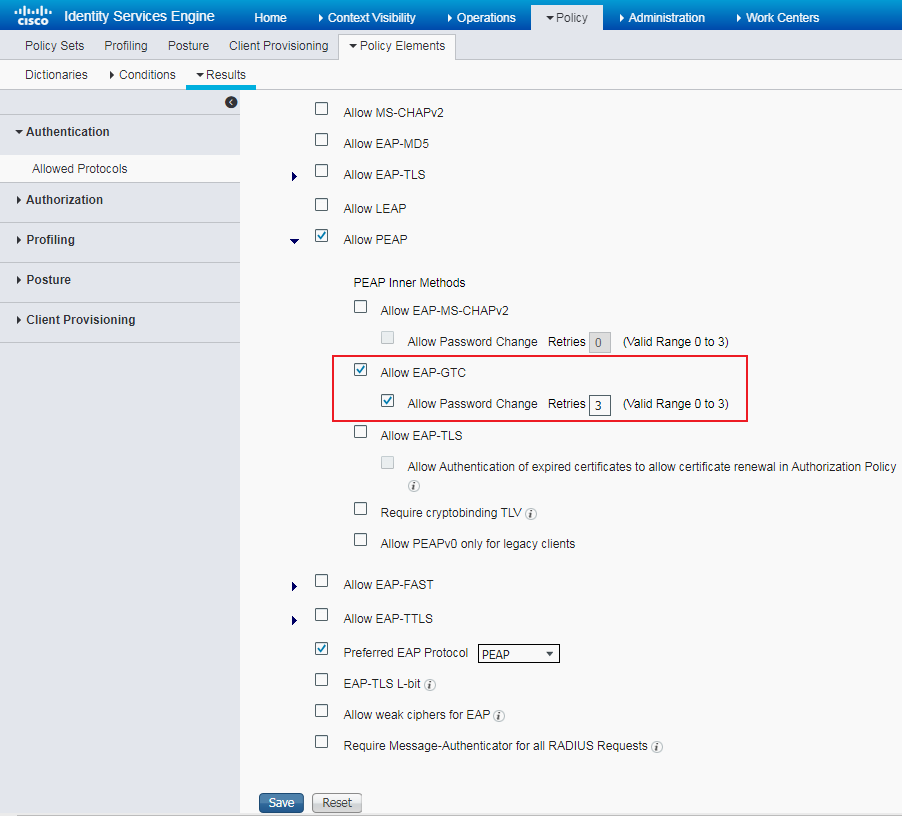
3. Configure the authentication and authorization policy set:
Navigate to Policy > Policy Sets. Click the plus sign (+) below Policy Sets, and create an authentication and authorization policy named 1x-id through LDAPS.
Figure 131 Creating a policy set
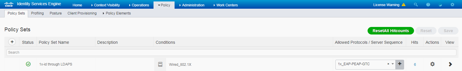
Figure 132 Use LDAP_Identity_Source456
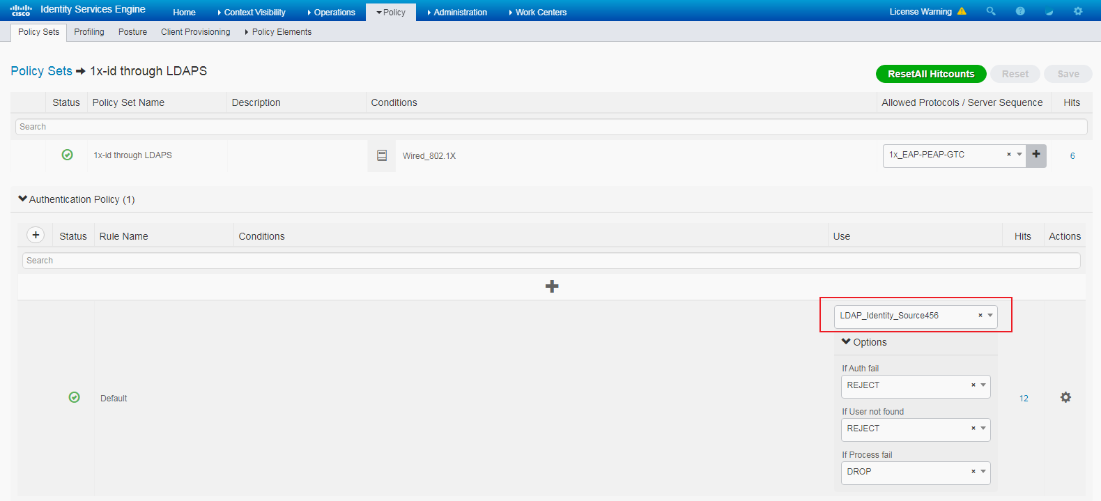
Verifying the configuration
1. Use iNode to log in from the Windows client:
Enter the username and password created on the Windows Server. In the Properties menu, select the Authentication Type as PEAP and the Sub-Type as GTC.
Figure 133 iNode login
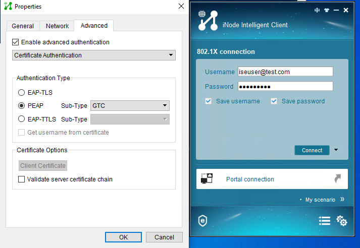
2. View server logs after the client comes online.
Figure 134 Server logs
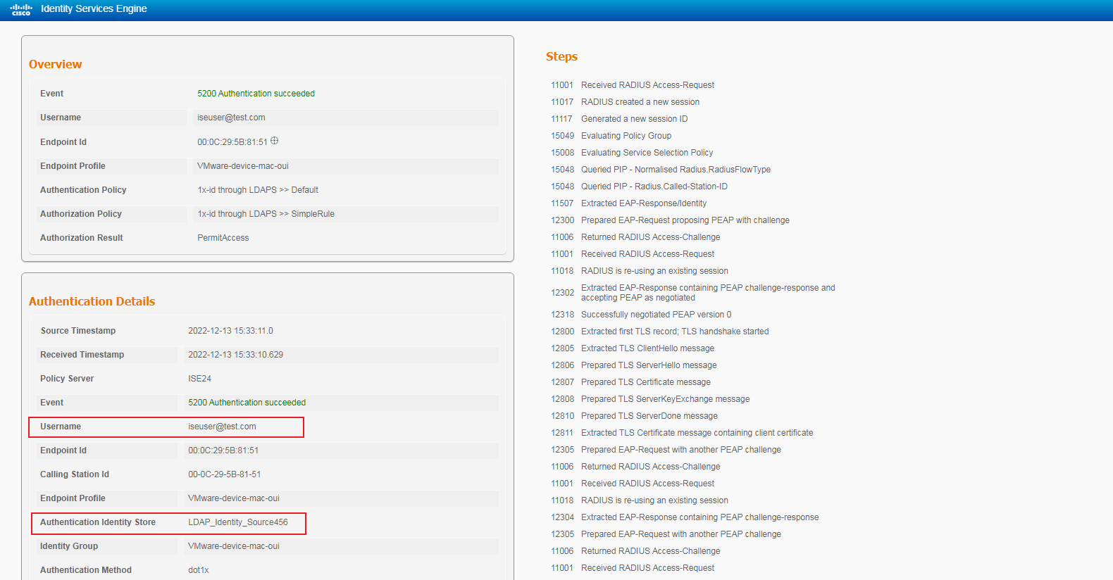
3. Verify that you can view the user information after the user comes online.
<Switch> display dot1x connection
Total connections: 1
Slot ID: 1
User MAC address: 000c-295b-8151
Access interface: GigabitEthernet1/0/21
Username: iseuser@test.com
User access state: Successful
Authentication domain: test.com
IPv4 address: 2.2.2.2
IPv4 address source: IP Source Guard
EAP packet identifier: 200
Authentication method: EAP
AAA authentication method: RADIUS
Initial VLAN: 2
Authorization untagged VLAN: N/A
Authorization tagged VLAN list: N/A
Authorization VSI: N/A
Authorization microsegment ID: N/A
Authorization ACL number/name: N/A
Authorization dynamic ACL name: N/A
Authorization user profile: N/A
Authorization CAR: N/A
Authorization URL: N/A
Authorization IPv6 URL: N/A
Authorization temporary redirect: Disabled
Start accounting: Successful
Real-time accounting-update failures: 0
Termination action: Default
Session timeout period: N/A
Online from: 2022/12/13 15:33:10
Online duration: 0h 1m 17s
Configuration files
#
dot1x
dot1x authentication-method eap
#
vlan 1
#
vlan 2
description toClients
arp snooping enable
#
vlan 3
description toAAAserver
#
interface Vlan-interface1
#
interface Vlan-interface2
description toClients
ip address 2.2.2.29 255.255.255.0
#
interface Vlan-interface3
description toAAAservers
ip address 3.3.3.29 255.255.255.0
#
interface GigabitEthernet1/0/2
port link-mode bridge
port access vlan 3
#
interface GigabitEthernet1/0/3
port link-mode bridge
port access vlan 2
dot1x
#
radius scheme ise
primary authentication 3.3.3.24 key cipher $c$3$2oLOvHdRilTBlb6n1yh3/MoXN8z/RMbctQ==
primary accounting 3.3.3.24 key cipher $c$3$fAhWH/rHm9hCcPq2PBWQa54YG9xKuQ1P0w==
timer realtime-accounting 20 second
user-name-format keep-original
#
#
domain test.com
authentication default radius-scheme ise
authorization default radius-scheme ise
accounting default radius-scheme ise
#
Examples: Configuring endpoint profiling
The following is an example for implementing endpoint profiling through SNMP and LLDP.
Network configuration
As shown in Figure 135, configure the switch to work in conjunction with the Cisco ISE server to perform endpoint profiling for the client.

Hardware and software versions used
This configuration example was created and verified on the following hardware and software versions:
|
Hardware |
Software version |
|
Switch (S5560X) |
R6618P27 |
|
Authentication server |
Cisco ISE V2.4.0.357 patch 8 |
|
Client operating system |
Windows 10 21H2 |
|
Authentication client |
iNode PC 7.3 (E513) |
Example: Configuring endpoint profiling
Prerequisites
This example provides only the configuration for authentication. Make sure that the client, switch, and server have network connectivity to communicate with one another.
Configuring the switch
Create an SNMP community and enable SNMP versions. To configure other switch settings, see "Configuring the switch."
[Switch] snmp-agent community read simple public
[Switch] snmp-agent sys-info version all
Configuring the ISE server
1. Configure a probe:
# Navigate to the Work Centers > Profiler > Node Config > Profiling Configuration page.
# Select HTTP, Network Scan (NMAP), and SNMPQUERY, configure SNMPQUERY settings.
Figure 136 Configuring probe settings
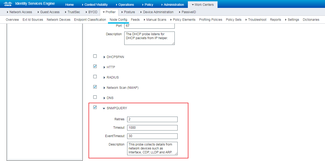
2. Configure SNMP:
# Navigate to the Work Centers > Profiler > Network Devices page.
# Select the corresponding switches and configure SNMP settings. Make sure the ISE server can obtain SNMP information of the switches.
Figure 137 Configuring SNMP settings
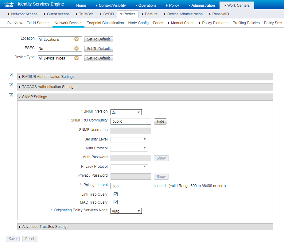
Configuring the Windows client
Installing LLDP-related modules
For the Windows system to send LLDP frames, you need to install LLDP-related modules online or offline to the Windows system. Make sure LLDP frames can be received by the switch.
This example installs LLDP-related modules offline to Windows 10 as follows:
1. Download WindowsTH-RSAT_WS2016-x64.msu by clicking https://download.microsoft.com/download/1/D/8/1D8B5022-5477-4B9A-8104-6A71FF9D98AB/WindowsTH-RSAT_WS2016-x64.msu, and save the file to a local path, for example, C:\Downloads.
2. Open CMD and execute the following commands:
MKDIR C:\Downloads\RSAT
MKDIR C:\Downloads\RSAT\x64
expand -f:* C:\Downloads\WindowsTH-RSAT_WS2016-x64.msu C:\Downloads\RSAT\x64
3. Enter C:\Downloads\RSAT\x64, and execute the Dism.exe /Online /Add-Package /PackagePath:".\WindowsTH-KB2693643-x64.cab" command.
Verifying LLDP configuration
Execute Enable-NetLldpAgent -NetAdapterName "AAAuser" in CMD to enable LLDP-related modules. Then, LLDP frames are automatically sent and received.
Figure 138 LLDP frames sent from Windows 10 (VMware VM)
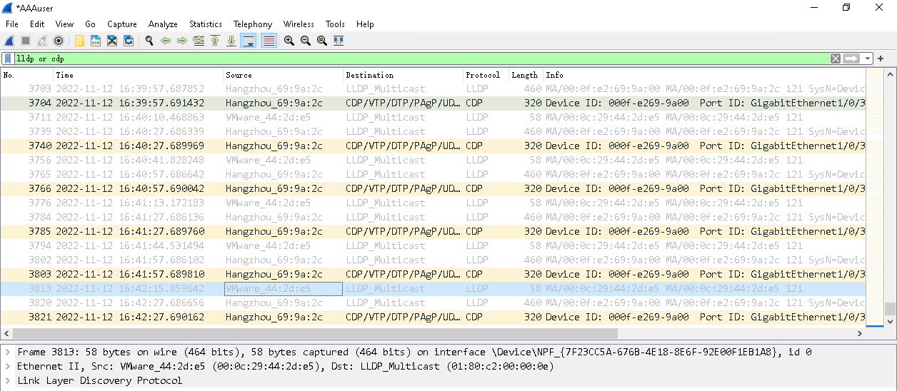
Figure 139 LLDP information on the switch
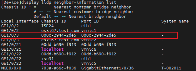
Configuring profiler settings
Viewing LLDP information
The minimum polling interval of the SNMPQUERY probe has been specified as 10 minutes.
To view LLDP information associated with an endpoint, select the endpoint on the Endpoint Classification tab after the polling finishes.
Figure 140 Viewing LLDP information of the endpoint
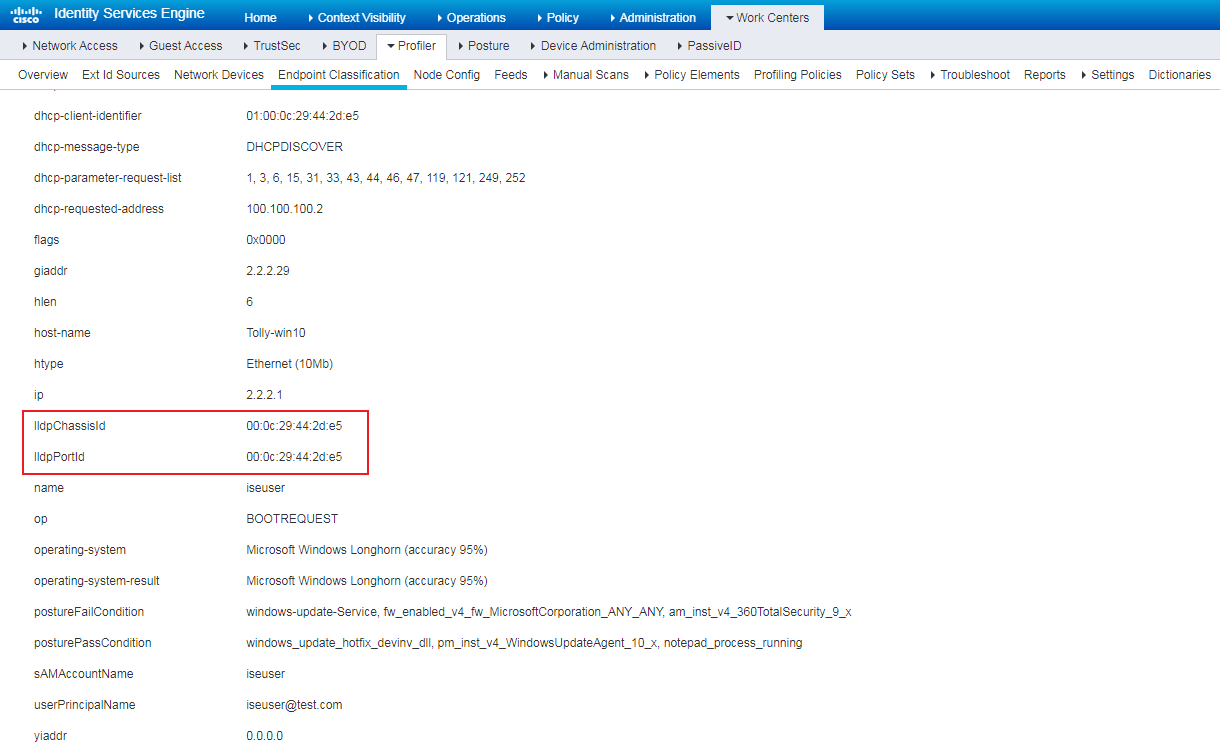
Creating a profiler policy
When you a profiler policy, configure a profiler condition that if the lldpChassisId field of endpoints contains 00:0c:29, increase the value for the Minimum Certainty Factor field to 500. If endpoints meet this condition, ISE assigns these endpoints to the same group.
If an endpoint also matches other profiler policies and the certainty factor values of these profiler policies are greater than 500, the endpoint displays only the profiler policy with the greatest certainty factor value.
Figure 141 Creating a profiler policy
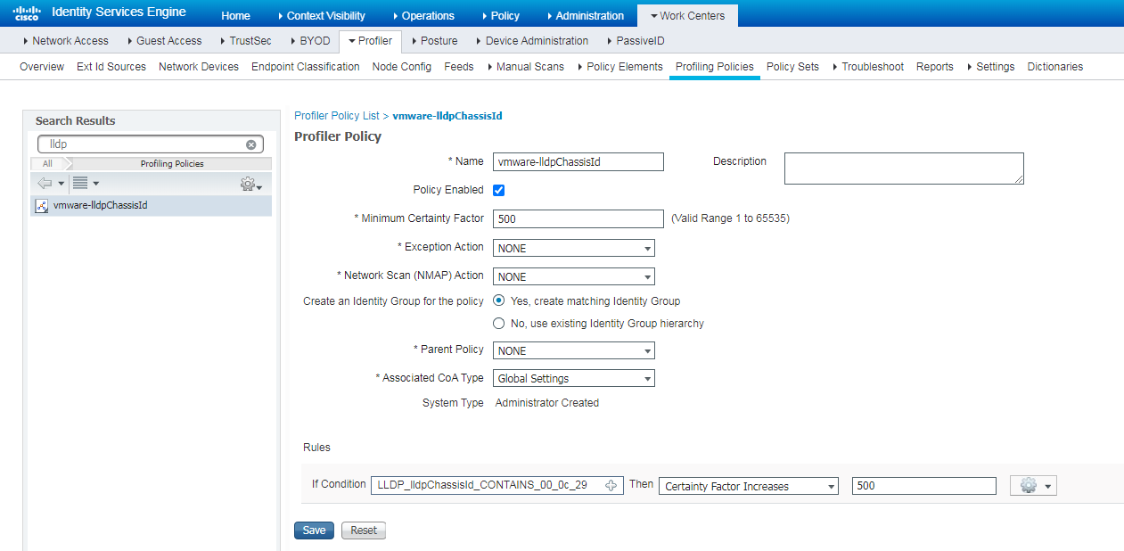
Verifying the configuration
Figure 142 Displaying vmware-lldpChassisId
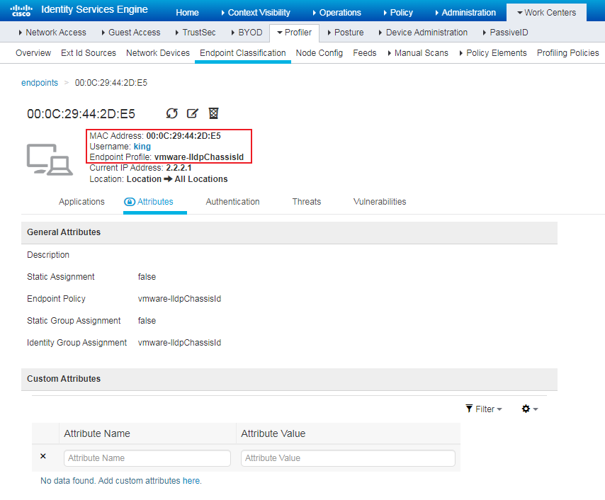
Figure 143 Displaying SNMPQuery Probe for EndPointSource
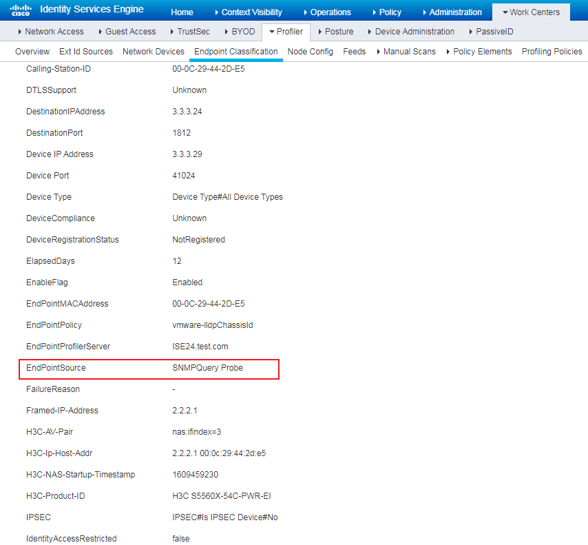
Configuration files
#
snmp-agent
snmp-agent community read cipher $c$3$KaeEzejbDaABoVp8gpCZyK8F7+BvOlj2jQ==
snmp-agent sys-info version all
#
For other configurations, see the corresponding authentication methods.
Examples: Configuring endpoint security posture assessment
Network configuration
As shown in Figure 144, configure the switch to work in conjunction with the Cisco ISE server to perform posture assessment for the client.

Hardware and software versions used
This configuration example was created and verified on the following hardware and software versions:
|
Hardware |
Software version |
|
Switch (S5560X) |
R6618P27 |
|
Authentication server |
Cisco ISE V2.4.0.357 patch 8 |
|
Client operating system |
Windows 10 21H2 |
|
Authentication client |
iNode PC 7.3 (E513) |
Example: Configuring endpoint security posture assessment
Prerequisites
This example provides only the configuration for authentication. Make sure that the client, switch, and server have network connectivity to communicate with one another.
Configuring the switch
Configure the switch as described in "Configuring the switch." This example configures the switch in an 802.1X network.
Configuring the ISE server
1. Upload resources required by client provisioning:
# Navigate to the Work Centers > Posture > Client Provisioning > Resources page, and then click Add.
# Select Agent resources from local disk to upload files from the local. If the ISE server can connect to the Internet, you can also select Agent resources from Cisco site.
You can obtain related files from the Cisco website.
Figure 145 Uploading files

Figure 146 Files that have been uploaded
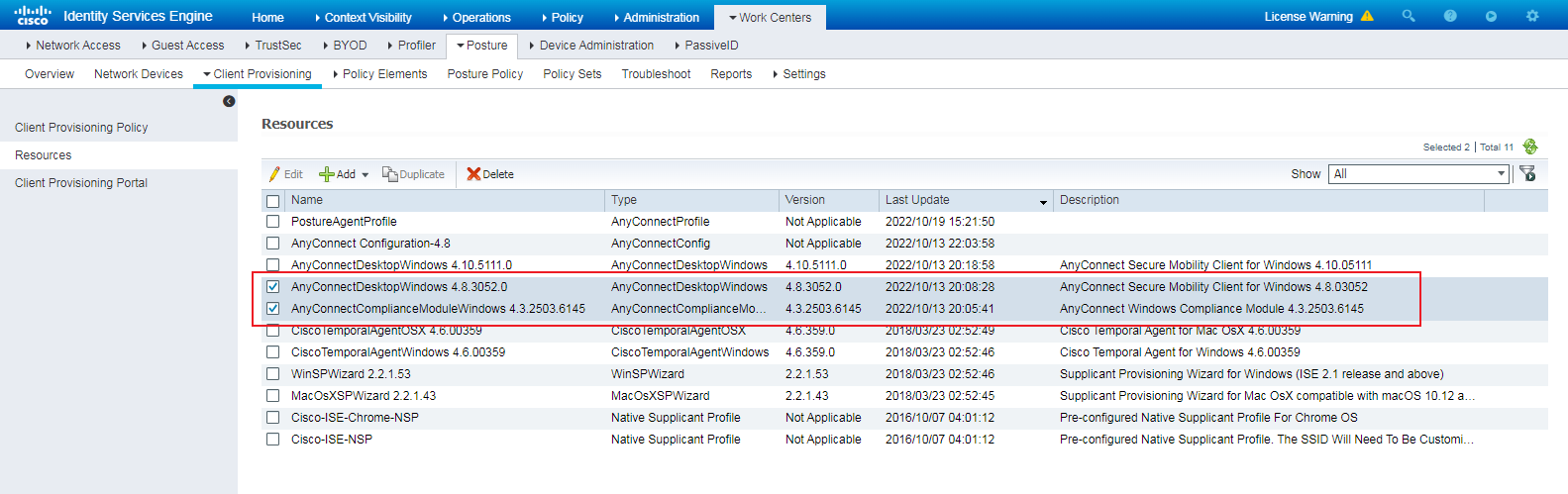
2. Create posture agent profile settings:
# Navigate to the Work Centers > Posture > Client Provisioning > Resources page.
# Configure Posture Agent Profile Settings. Specify the name as PostureAgentProfile.
For ease of debugging, enable the Enable Rescan Button option, which is deployed to AnyConnect as the setting in a configuration file.
Figure 147 Configuring posture agent profile settings
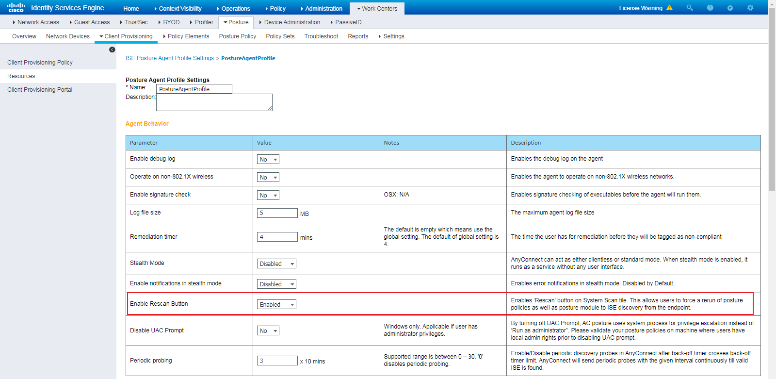
You must specify the option marked with an asterisk (*). This example specifies the ISE IP address.
Figure 148 Specifying the option marked with an asterisk
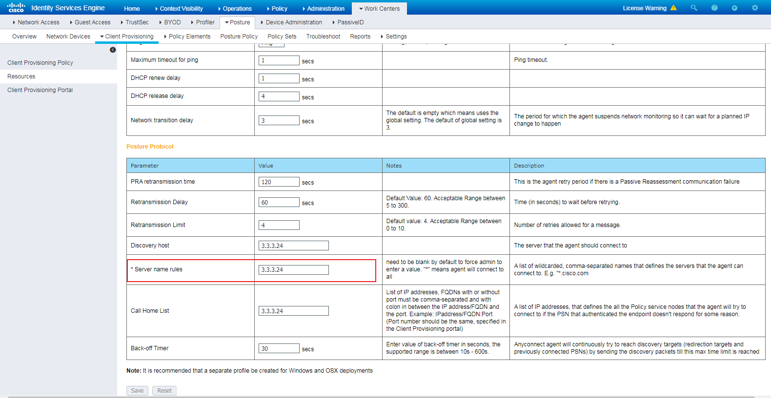
3. Create an AnyConnect configuration:
# Specify the name as AnyConnect Configuration-4.8.
# Bind PostureAgentProfile to * ISE Posture.
# Bind the AnyConnectComplianceModuleWindows 4.3.2503.6145 file that is uploaded to Compliance Module.
Figure 149 AnyConnect configuration related settings
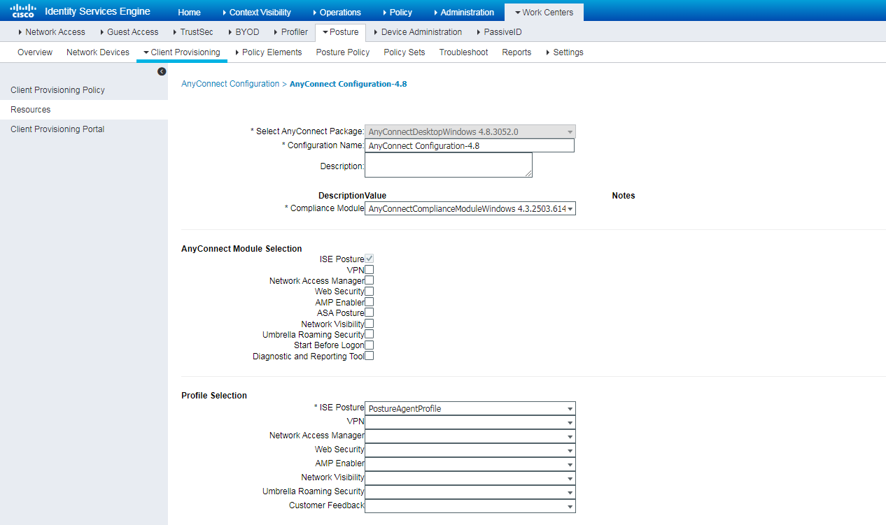
4. Create a client provisioning policy:
# Navigate to the Work Centers > Posture > Client Provisioning > Client Provisioning Policy page.
# Select AnyConnect Configuration-4.8.
Figure 150 Creating a client provisioning policy
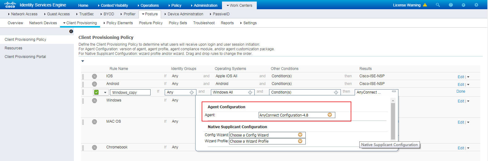
5. Create an application condition:
# Navigate to the Work Centers > Posture > Policy Elements > Conditions > Application page.
# Create an application condition. This example creates an application condition named notepad running check to check the running status of notepad.
Figure 151 Creating an application condition
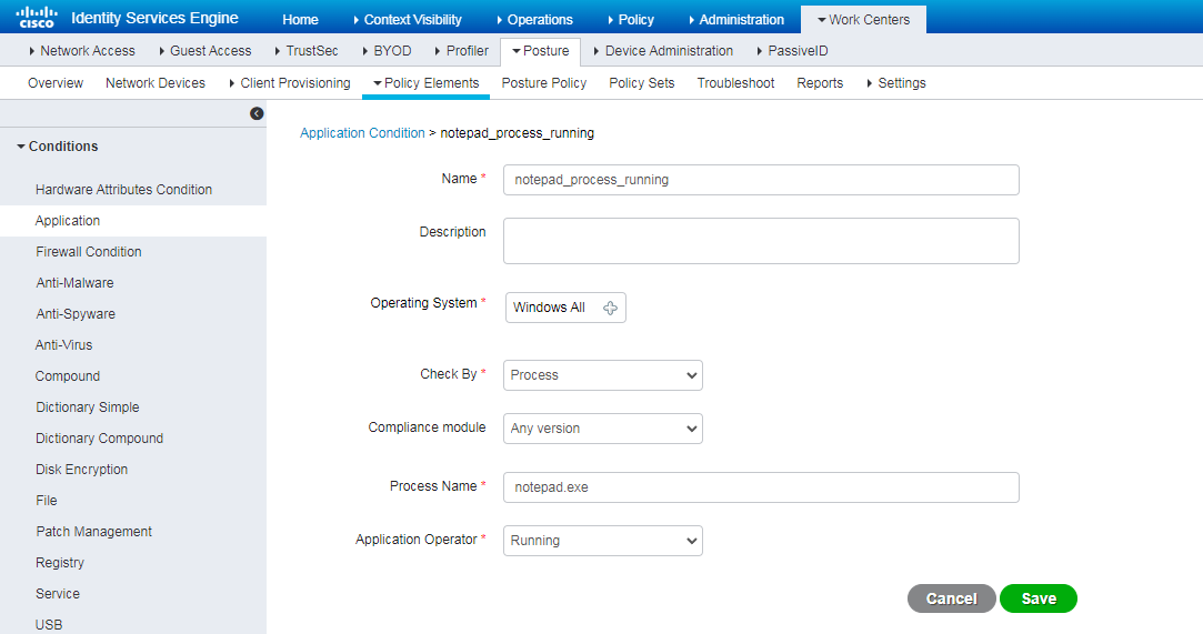
6. Create a remediation:
# Navigate to the Work Centers > Posture > Policy Elements > Remediations > Launch Program page.
# Create a launch program remediation named notepad_Launch_Program_Remediation.
Figure 152 Creating a remediation
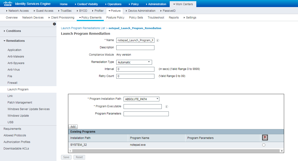
7. Creating a requirement:
# Navigate to the Work Centers > Posture > Policy Elements > Remediations > Requirements page.
# Create a requirement and bind the requirement to the condition and the remediation that have been created in previous steps.
Figure 153 Creating a requirement
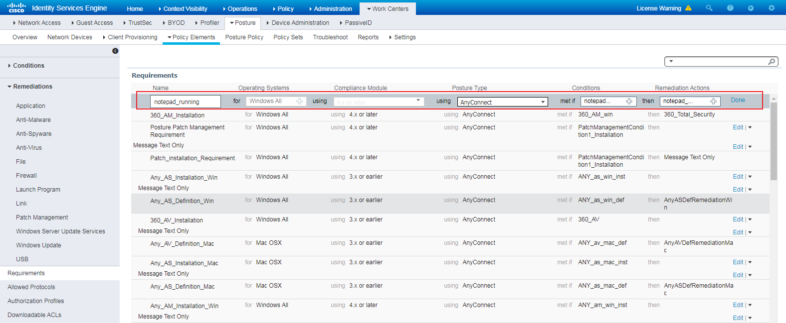
8. Create a posture policy:
# Navigate to the Work Centers > Posture > Posture Policy page.
# Create a posture policy as follows:
- Select 4.x or later in the Compliance Module column because AnyConnectComplianceModuleWindows 4.3.2503.6145 has been uploaded.
- Select notepad_process_running that has been created in the Other Conditions column.
Figure 154 Creating a posture policy
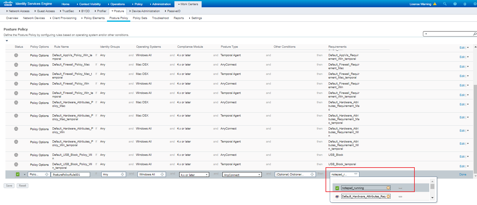
9. Create an authorization profile:
# Navigate to the Policy > Policy Elements > Results > Authorization > Authorization Profiles page.
# Create an authorization profile named CPP-redirect for client provisioning and bind an ACL to the authorization profile. The authorization profile redirects endpoint Web access to CPP for downloading the AnyConnect client when an endpoint's compliance is unknown or an endpoint is non-compliant.
Figure 155 Creating an authorization profile
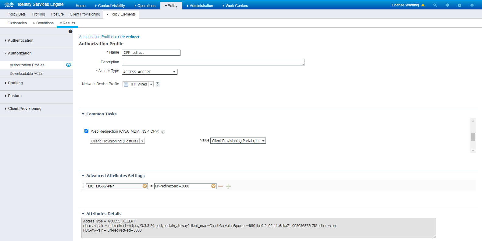
10. Create a policy set:
# Navigate to the Work Centers > Posture > Policy Sets page.
# Create a policy set named Secure Mobility.
Figure 156 Creating a policy set
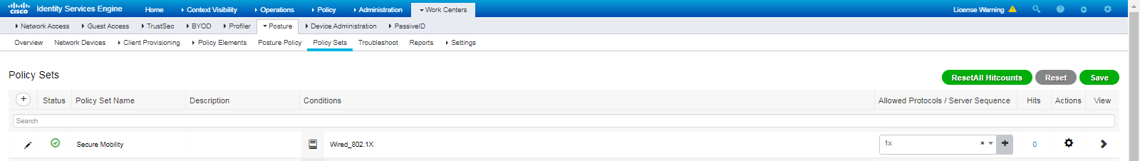
# Create three authorization policies to meet the following requirements:
- Allow an endpoint to access only CPP when the endpoint's compliance is unknown or the endpoint is non-compliant.
- Apply the PermitAcess profile to compliant endpoints
Figure 157 Creating authorization policies
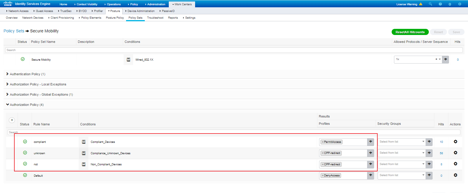
Verifying the configuration
Installing AnyConnect for client provisioning
1. Connect the endpoint to the 802.1X network successfully. The browser is automatically redirected to the Client Provisioning portal.
Figure 158 Client Provisioning Portal
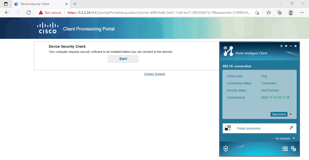
2. Click Start and waiting for a while.
Figure 159 Starting device security check
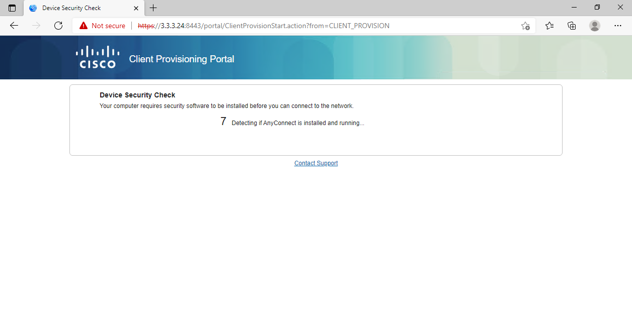
3. Click Click here to download and install AnyConnect as prompted.
Figure 160 Clicking Click here to download and install AnyConnect
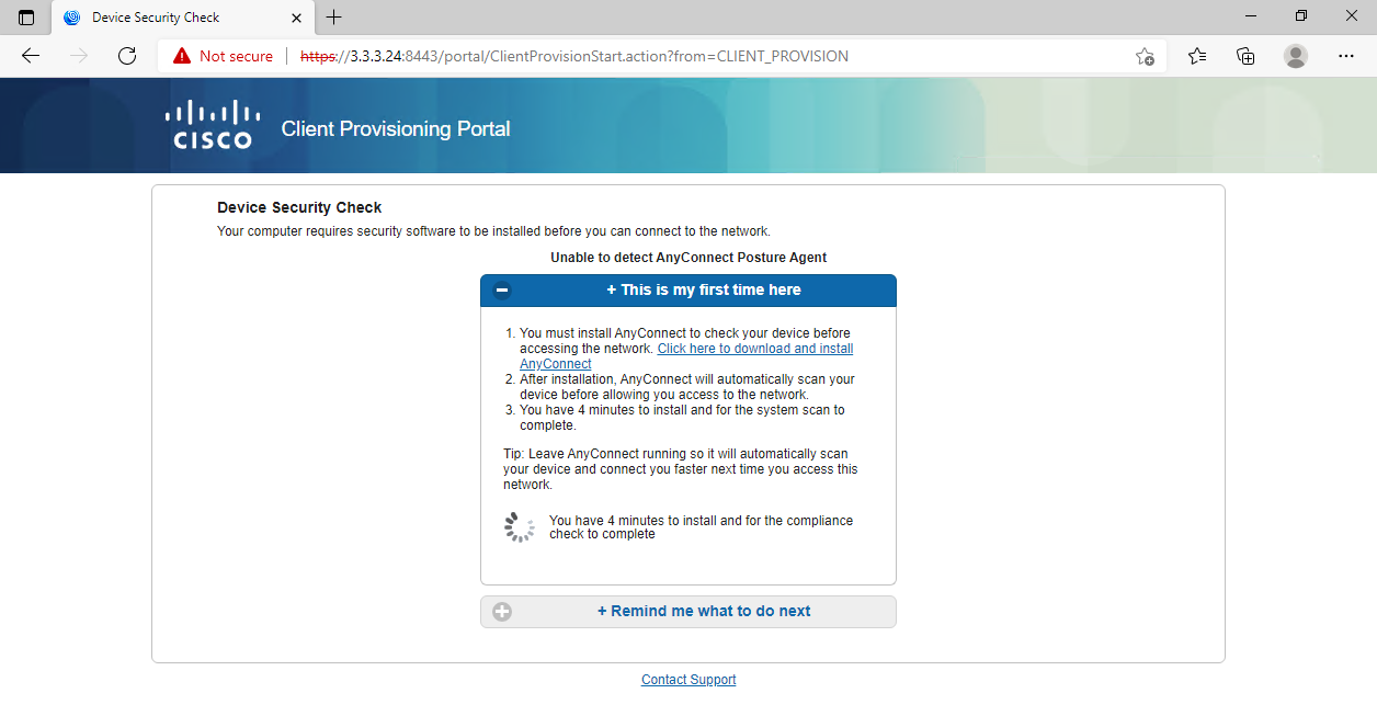
4. Download and open the software package.
Figure 161 Download and open the software package
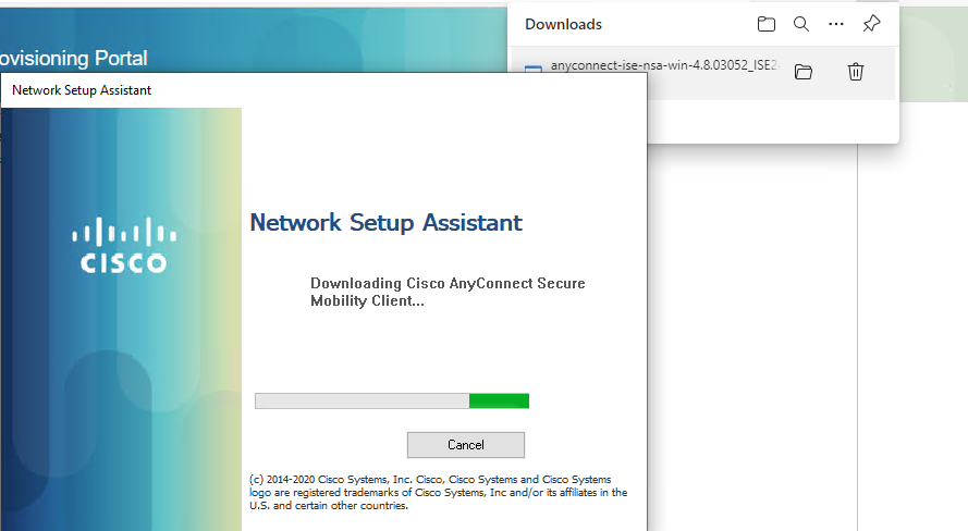
5. Click Connect Anyway.
Figure 162 Clicking Connect Anyway
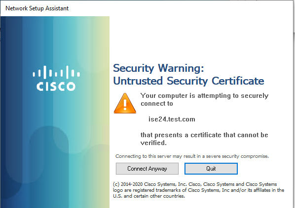
Figure 163 Waiting for the installation
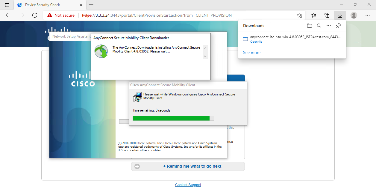
Verifying posture assessment
1. AnyConnect runs automatically after being installed. Then, click Connect Anyway.
Figure 164 Clicking Connect Anyway
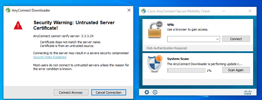
2. Based on previously configured settings including posture policy settings, AnyConnect automatically opens notepad.exe when it detects that notepad.exe is not opened. To skip other optional check items, click Skip All.
Figure 165 Opening notepad.exe
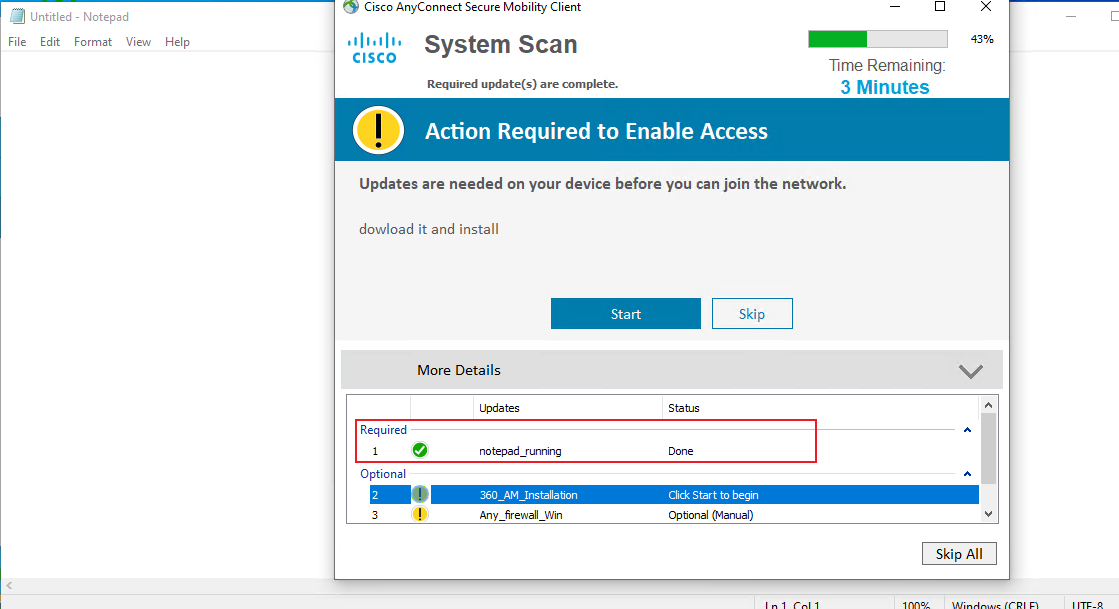
3. AnyConnect detects that the endpoint is posture-compliant through system scan.
Figure 166 Endpoint detected to be compliant
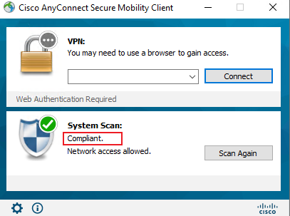
Figure 167 AnyConnect scan summary
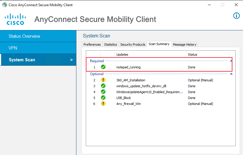
4. Review ISE logs. The logs show that the endpoint is at first assigned authorization policy Secure Mobility >> unknown and authorization profile CPP-redirect. After AnyConnect is installed and the endpoint passes AnyConnect check, ISE automatically issues CoA reauthentication. At this time, the endpoint is assigned authorization policy Secure Mobility >> compliant and authorization profile PermitAccess because the endpoint has been posture-compliant.
Figure 168 Reviewing live logs
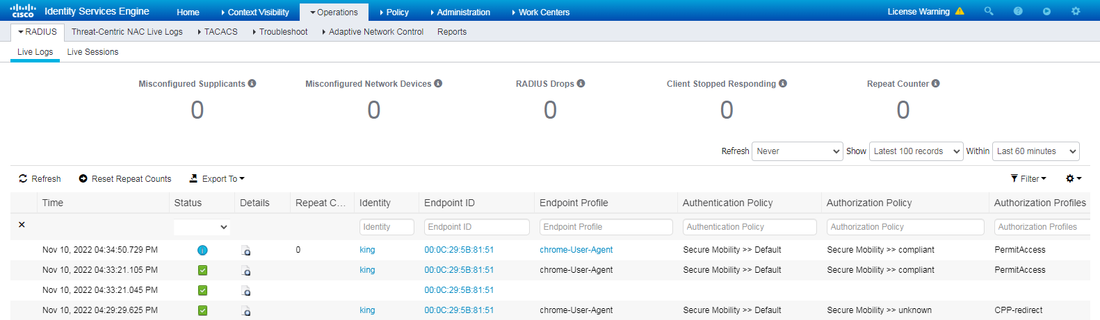
Figure 169 Reauthentication triggered by posture status changed
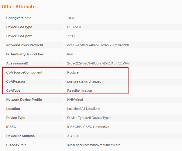
Configuration files
#
dot1x
dot1x authentication-method eap
#
vlan 1
#
vlan 2
description toClients
arp snooping enable
#
vlan 3
description toAAAserver
#
interface Vlan-interface1
#
interface Vlan-interface2
description toClients
ip address 2.2.2.29 255.255.255.0
#
interface Vlan-interface3
description toAAAservers
ip address 3.3.3.29 255.255.255.0
#
interface GigabitEthernet1/0/2
port link-mode bridge
port access vlan 3
#
interface GigabitEthernet1/0/3
port link-mode bridge
port access vlan 2
dot1x
#
radius scheme ise
primary authentication 3.3.3.24 key cipher $c$3$2oLOvHdRilTBlb6n1yh3/MoXN8z/RMbctQ==
primary accounting 3.3.3.24 key cipher $c$3$fAhWH/rHm9hCcPq2PBWQa54YG9xKuQ1P0w==
timer realtime-accounting 20 second
user-name-format keep-original
#
#
domain test.com
authentication default radius-scheme ise
authorization default radius-scheme ise
accounting default radius-scheme ise
#
