- Table of Contents
- Related Documents
-
| Title | Size | Download |
|---|---|---|
| 01-Aruba ClearPass Integration | 5.55 MB |
|
|
|
H3C Switches and Aruba ClearPass Authentication Server |
|
Integration Guide |
|
|
|
|
Copyright © 2023 New H3C Technologies Co., Ltd. All rights reserved.
No part of this manual may be reproduced or transmitted in any form or by any means without prior written consent of New H3C Technologies Co., Ltd.
Except for the trademarks of New H3C Technologies Co., Ltd., any trademarks that may be mentioned in this document are the property of their respective owners.
The information in this document is subject to change without notice.
H3C switches and Aruba ClearPass compatibility in authentication methods
Examples: Integrating the switch with ClearPass for MAC authentication
Example: Integrating the switch with ClearPass for MAC authentication with a shared user account
Example: Integrating the switch with ClearPass for MAC authentication with MAC-based user accounts
Examples: Integrating the switch with ClearPass for 802.1X authentication
Example: Integrating the switch with ClearPass for 802.1X CHAP authentication
Example: Integrating the switch with ClearPass for 802.1X PAP authentication
Example: Integrating the switch with ClearPass for 802.1X EAP-MD5 authentication
Example: Integrating the switch with ClearPass for 802.1X certificate authentication
Example: Integrating the switch with ClearPass for portal authentication
Example: Integrating the switch with ClearPass for authentication with user profile assignment
Example: Integrating the switch with ClearPass for authentication with CAR assignment
Examples: Integrating the switch with ClearPass for periodic 802.1X or MAC reauthentication
Example: Enabling periodic reauthentication upon session timeout
Example: Logging off users upon session timeout
Example: Performing periodic reauthentication prior to session timeout to keep users online
Example: Logging off users upon session timeout
Example: Integrating the switch with ClearPass for authentication at a redirect URL
Examples: Integrating the switch with ClearPass for authentication through RADIUS DAE
Example: Forcing users offline by sending Disconnect Messages
Example: Disabling the user-attached switch port
Example: Re-enabling the user-attached switch port
Example: Configuring HWTACACS authentication for SSH users that access the switch
Configuring the ClearPass server
Introduction
This document provides examples for integrating H3C switches with an Aruba ClearPass server for user authentication. This document provides examples for the following authentication and authorization features:
· MAC authentication.
· 802.1X authentication.
· Portal authentication.
· Authorization VLAN assignment.
· Authorization ACL assignment.
· Authorization user profile assignment.
· Authorization CAR attributes.
· Reauthentication.
· URL redirection.
· RADIUS DAE.
· HWTACACS authentication for SSH users that access the switch.
· RADIUS authentication for users that access the switch through SSH, Telnet, or the console port.
H3C switches can be integrated with the Aruba ClearPass authentication server. Support for the authentication and authorization features depends on the device model. For more information, see the security configuration guide for the device.
H3C switches and Aruba ClearPass compatibility in authentication methods
|
H3C switches |
Aruba ClearPass |
Compatibility |
|
MAC authentication with a shared user account |
CHAP authentication |
Yes |
|
MAC authentication with MAC-based user accounts |
CHAP authentication |
Yes |
|
802.1X CHAP authentication |
CHAP authentication |
Yes |
|
802.1X PAP authentication |
PAP authentication |
Yes |
|
802.1X EAP authentication |
EAP-MD5 authentication |
Yes |
|
802.1X EAP authentication |
Certificate-based authentication |
Yes |
|
Portal authentication |
CHAP authentication |
Yes |
|
Authorization VLAN |
· VLAN ID authorization · VLAN name authorization · VLAN group name authorization · Multi-VLAN authorization · Auto VLAN authorization (VLAN authorization with the tag attribute) |
Yes |
|
Authorization ACL |
Authorization static ACL |
Yes |
|
Authorization user profile |
Authorization user profile |
Yes |
|
Authorization CAR attributes |
Authorization CAR |
Yes |
|
Reauthentication |
· Reauthentication after the session timeout timer expires · Forcible user offline after the session timeout timer expires · Reauthentication after the session timeout timer expires according to the periodic reauthentication timer |
Yes |
|
Authorization URL redirection |
URL redirection |
Yes |
|
RADIUS DAE |
· Forcible user offline by disconnecting request messages · CoA-Session termination by disabling host port · CoA-Session termination by bouncing host port |
Yes |
|
HWTACACS authentication for SSH users that access the switch |
- |
Yes |
|
RADIUS authentication for users that access the switch through SSH, Telnet, or the console port |
- |
Yes |
Prerequisites
The following information applies to H3C switches. Procedures and information in the examples might be slightly different depending on the software or hardware version of the switch and the software version of Aruba ClearPass server.
The configuration examples were created and verified in a lab environment, and all the devices were started with the factory default configuration. When you are working on a live network, make sure you understand the potential impact of every configuration item on your network.
Restrictions and guidelines
When you integrate an H3C switch with Aruba ClearPass server for MAC, 802.1X, or portal authentication, you must add a minimum of one attribute entry in the enforcement profile on the server. If no enforcement profile is available, the server generates an alarm when it authenticates a client.
Examples: Integrating the switch with ClearPass for MAC authentication
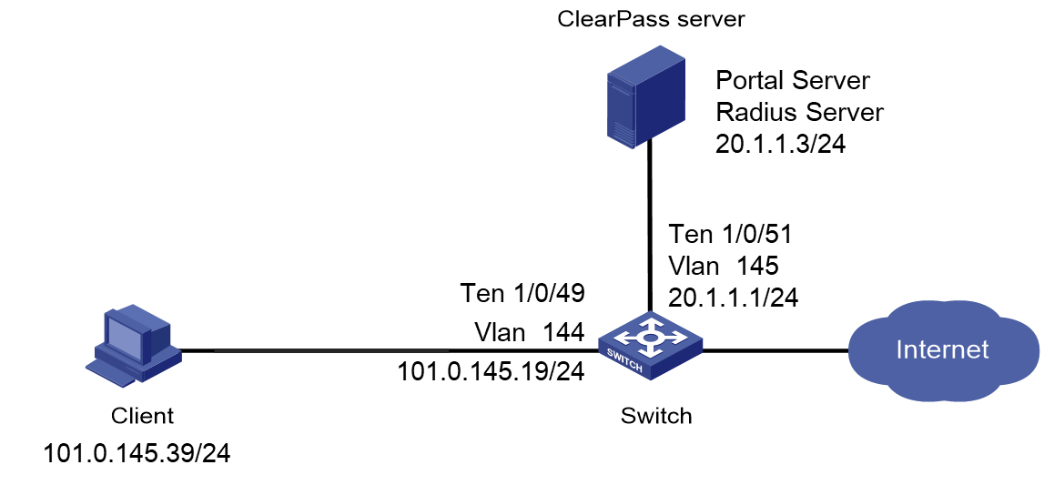
Network configuration
As shown in Figure 1, configure the switch to work in conjunction with a ClearPass server to do MAC authentication on the client connected to Ten-GigabitEthernet 1/0/49. The client must pass MAC authentication to access network resources.
Configure the switch as follows:
· Use the ClearPass server as the RADIUS server to perform MAC authentication for the client.
· Create a shared account with the specified username and password for MAC authentication users, or use the MAC address of the client as the username and password for MAC authentication.

Software versions used
This configuration example was created and verified on the following hardware and software versions:
|
Hardware |
Software version |
|
H3C S5130-HI switch |
R3507P02 |
|
Aruba ClearPass server |
Aruba ClearPass Policy Manager (CPPM) v6.9.7 |
Example: Integrating the switch with ClearPass for MAC authentication with a shared user account
Prerequisites
This example provides only the configuration for authentication. Make sure that the client, switch, and server have network connectivity to communicate with one another.
Configuring the switch
# Create a RADIUS scheme named radius1, specify the ClearPass server at 20.1.1.3 for user authentication and accounting, set the shared key to 123456 in plaintext form, and exclude domain names from the usernames sent to the RADIUS server.
<Device> system-view
[Device] radius scheme radius1
[Device-radius-radius1] primary authentication 20.1.1.3
[Device-radius-radius1] primary accounting 20.1.1.3
[Device-radius-radius1] key authentication simple 123456
[Device-radius-radius1] key accounting simple 123456
[Device-radius-radius1] user-name-format without-domain
[Device-radius-radius1] quit
# Configure the switch to use CHAP for MAC authentication.
[Device] mac-authentication authentication-method chap
# Create an ISP domain named mac-auth and apply the RADIUS scheme to the ISP domain for authentication, authorization, and accounting.
[Device] domain mac-auth
[Device-isp-mac-auth] authentication default radius-scheme radius1
[Device-isp-mac-auth] authorization default radius-scheme radius1
[Device-isp-mac-auth] accounting default radius-scheme radius1
[Device-isp-mac-auth] quit
# Create VLANs 144 and 145 and VLAN-interfaces 144 and 145, and assign IP addresses to the VLAN interfaces.
[Device] vlan 144
[Device-vlan144] quit
[Device] interface Vlan-interface 144
[Device-Vlan-interface144] ip address 101.0.145.19 255.255.255.0
[Device-Vlan-interface144] quit
[Device] vlan 145
[Device-vlan145] quit
[Device] interface Vlan-interface 145
[Device-Vlan-interface145] ip address 20.1.1.1 255.255.255.0
[Device-Vlan-interface145] quit
# Assign Ten-GigabitEthernet 1/0/49 to VLAN 144 and enable MAC authentication on Ten-GigabitEthernet 1/0/49.
[Device] interface Ten-GigabitEthernet 1/0/49
[Device-Ten-GigabitEthernet1/0/49] port access vlan 144
[Device-Ten-GigabitEthernet1/0/49] mac-authentication
[Device-Ten-GigabitEthernet1/0/49] quit
# Assign Ten-GigabitEthernet 1/0/51 to VLAN 145.
[Device] interface Ten-GigabitEthernet 1/0/51
[Device-Ten-GigabitEthernet1/0/51] port access vlan 145
[Device-Ten-GigabitEthernet1/0/51] quit
# Specify ISP domain mac-auth as the default ISP domain.
[Device] domain default enable mac-auth
# Specify ISP domain mac-auth as the MAC authentication domain.
[Device] mac-authentication domain mac-auth
# Configure the offline detection and quiet timers for MAC authentication.
[Device] mac-authentication timer offline-detect 180
[Device] mac-authentication timer quiet 180
# Specify username user and password 123456 in plaintext form for the account shared by MAC authentication users.
[Device] mac-authentication user-name-format fixed account user password simple 123456
# Enable MAC authentication globally.
[Device] mac-authentication
Configuring the ClearPass server
1. Log in to the ClearPass server:
# Enter the management IP address of the ClearPass server in the address bar of the Web browser.
Figure 2 Logging in to ClearPass

# Click ClearPass Policy Manager.
# On the page that opens, enter the login username and password, and then click Log In. In this example, the username and password are admin and Pass1234_, respectively.
Figure 3 Logging in to ClearPass Policy Manager

2. Add a user:
# From the left navigation pane, select Configuration > Identity > Local Users.
# On the page that opens, click Add in the upper right corner.
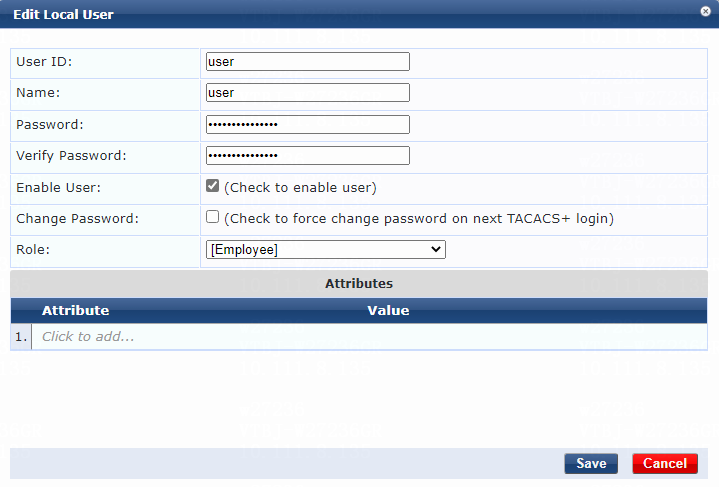
# Configure the user account:
a. Set the user ID and name.
Make sure the user ID is the same as the username specified on the device for MAC authentication. In this example, user is used as both the user ID and name.
b. Set the password and then verify the password.
Make sure it is the same as the password specified on the device for MAC authentication. In this example, 123456 is used.
c. Select the Enable User option to enable the user account.
d. Select predefined role Employee or a user-defined role. In this example, predefined role Employee is selected.
e. Click Add.
Figure 4 Adding a user

3. Configure a role mapping:
# From the left navigation pane, select Configuration > Identity > Role Mappings.
# On the Policy tab, click Add in the upper right corner.
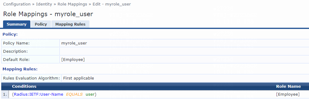
# Add a role mapping policy:
a. Specify the policy name. In this example, myrole_user is used.
b. Specify the default role as [Employee].
# Click Next to open the Mapping Rules tab, and then click Add Rule.
# On the page that opens, select the Select first match option for the Rules Evaluation Algorithm field and specify a mapping rule:
c. Select type Radius:IETF.
d. Select name User-Name.
e. Select operator EQUALS.
f. Enter the user ID you have specified in step 2 for the Value field. In this example, the user ID is user.
g. Select role name [Employee].
h. Click Save.
Figure 5 Role mapping summary

4. Add the switch to ClearPass Policy Manager:
# From the left navigation pane, select Configuration > Network > Devices.
# On the page that opens, click Add in the upper right corner.
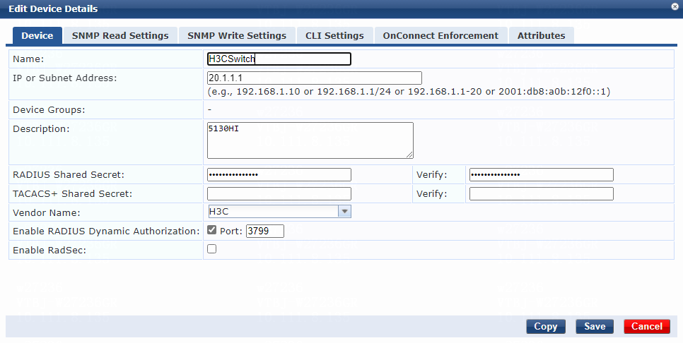
# Add the switch:
a. Specify the name of the switch. In this example, H3CSwitch is used.
b. Specify the IP address of the switch, for example, 20.1.1.1.
Make sure the ClearPass server can reach this IP address.
c. (Optional.) Enter a description of the switch for management purposes. In this example, 5130HI is used.
d. Configure the RADIUS shared secret and then verify the shared secret.
Make sure the shared secret specified on the server is the same as the shared key specified on the switch for MAC authentication. In this example, 123456 is used.
e. Select vendor name H3C.
f. Enable RADIUS dynamic authorization (the default port is 3799).
g. Click Add.
Figure 6 Adding a device

5. Add a device group:
# From the left navigation pane, select Configuration > Network > Device Groups.
# On the page that opens, click Add in the upper right corner.
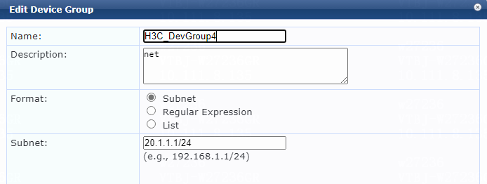
# Configure the device group:
a. Specify the name of the device group. In this example, H3C_DevGroup4 is used.
b. (Optional.) Enter a description of the device group for management purposes. In this example, net is used.
c. Select format Subnet.
d. Specify a subnet in network_address/mask_length format (CIDR notation).
Make sure the ClearPass server can reach this subnet. In this example, 20.1.1.1/24 is used.
e. Click Save.
Figure 7 Adding a device group

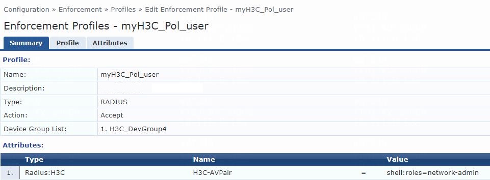
6. Add an enforcement profile:
# From the left navigation pane, select Configuration > Enforcement > Profiles. On the page that opens, click Add in the upper right corner.
a. On the Profile tab, select RADIUS Based Enforcement in the Template field and set the name to myH3C_Pol_user.
b. (Optional.) Enter a description of the profile.
c. Set the action to Accept.
d. Select device group H3C_DevGroup4 from the device group list.
e. Click Next.
f. On the Attributes tab, select Radius:H3C from the type list, H3C-AVPair from the name list, and set the attribute value to shell:roles=network-admin.
g. Click Save.
Figure 8 Enforcement profile summary

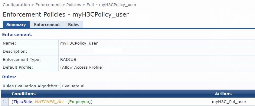
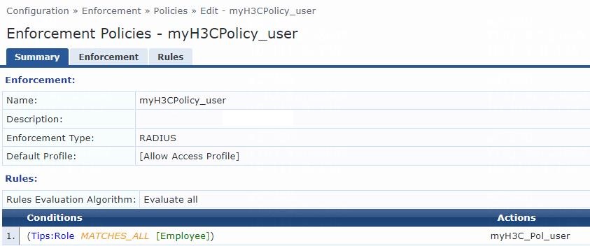
# From the left navigation pane, select Configuration > Enforcement > Policies.
# On the Enforcement tab, click Add in the upper right corner.
# Configure the policy:
a. Set the policy name to myH3CPolicy_user.
b. (Optional.) Enter a description of the enforcement policy for management purposes.
c. Select enforcement type RADIUS.
d. Select [Allow Access Profile] as the default profile.
# Click Next to open the Rules tab, and then click Add Rule.
# On the page that opens, select a rules evaluation algorithm for the Rules Evaluation Algorithm field. In this example, Select all matches is used. Then specify the following enforcement policy rules parameters:
a. Select type Tips.
b. Select name Role.
c. Select operator MATCHES_ALL.
d. Select value [Employee].
e. Select enforcement profile myH3C_Pol_user.
f. Click Save.
Figure 9 Enforcement policy summary

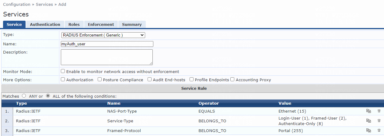
8. Add a service:
# From the left navigation pane, select Configuration > Services.
# On the page that opens, click Add in the upper right corner.
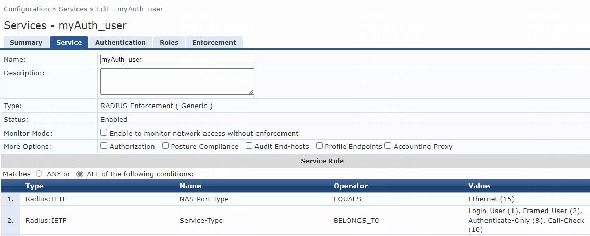
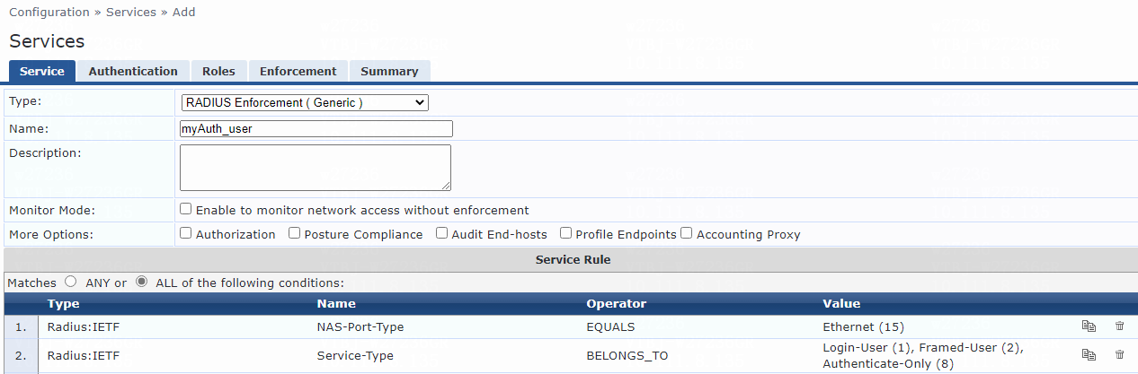
# On the Service tab, configure the service parameters:
a. Select RADIUS Enforcement (Generic) from the Type field.
b. Set the name to myAuth_user.
c. Select ALL of the following conditions for the Matches field.
d. Configure one rule to match Ethernet NAS ports. In the rule, set the type to Radius:IETF, name to NAS-Port-Type, operator to EQUALS, and value to Ethernet (15).
e. Configure another rule to match services. In the rule, set the type to Radius:IETF, name to Service-Type, operator to BELONGS_TO, and value to Login-User (1), Framed-User (2), Authenticate-Only (8), and Call-Check (10).
f. Click Save.
Figure 10 Adding a service
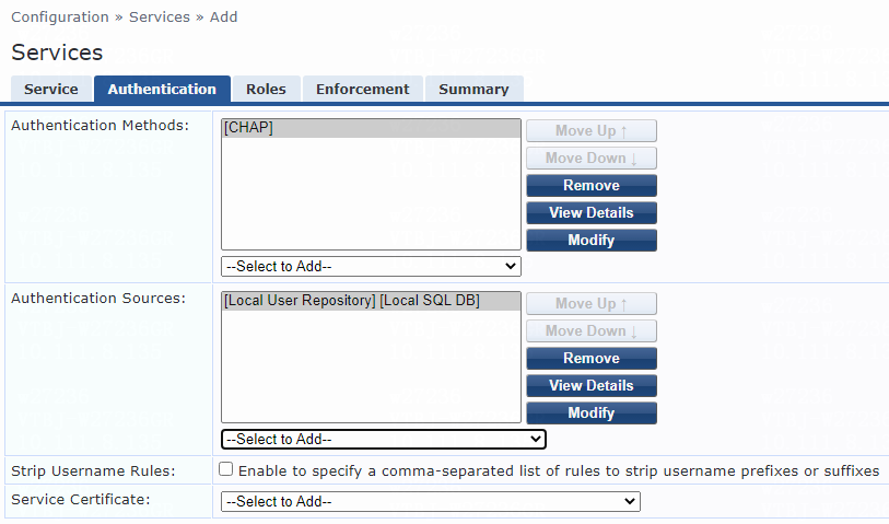
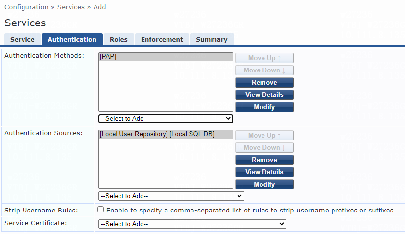
# On the Authentication tab, select [CHAP] from the Authentication Methods list and select [Local User Repository][Local SQL DB] from the Authentication Sources list.
Figure 11 Configuring authentication
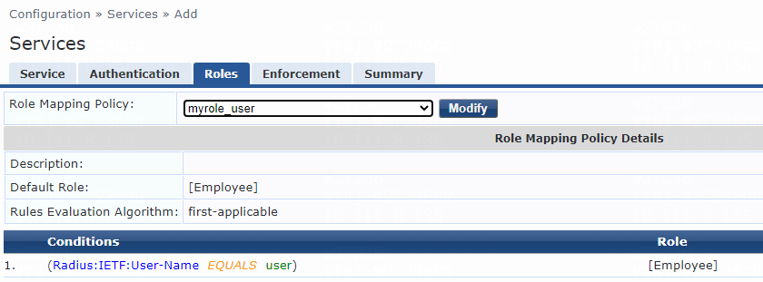
# On the Roles tab, select myrole_user from the Role Mapping Policy list, and then click Save.
Figure 12 Configuring roles
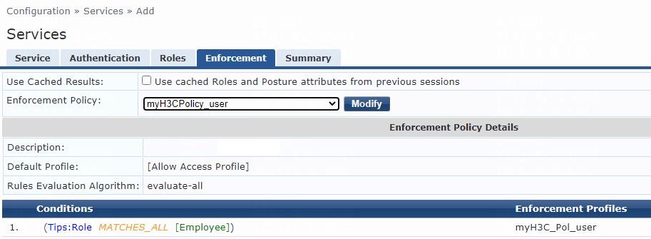
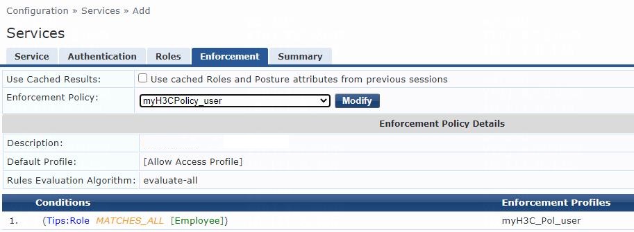
# On the Enforcement tab, select enforcement policy myH3CPolicy_user, and then click Save.
Figure 13 Configuring enforcement
Verifying the configuration
1. On the client, ping the ClearPass server to verify that you can pass MAC authentication and come online. (Details not shown.)
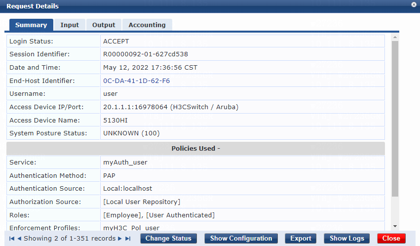
2. On the ClearPass server, view user access request details:
# From the left navigation pane, select Monitoring > Live Monitoring > Access Tracker.
# On the page that opens, view the access request record and verify that the client is online. To view details of the access request record, click the access request record.
Figure 14 Viewing access request details

3. On the switch, use the display mac-authentication connection command to display information about online MAC authentication users.
[Device] display mac-authentication connection
Total connections: 1
Slot ID: 1
User MAC address: 0cda-411d-62f6
Access interface: Ten-GigabitEthernet1/0/49
Username: user
User access state: Successful
Authentication domain: mac-auth
IPv4 address: 101.0.145.39
Initial VLAN: 144
Authorization untagged VLAN: N/A
Authorization tagged VLAN: N/A
Authorization ACL number/name: N/A
Authorization dynamic ACL name: N/A
Authorization user profile: N/A
Authorization CAR: N/A
Authorization URL: N/A
Termination action: Default
Session timeout period: N/A
Online from: 2022/05/13 09:53:10
Online duration: 0h 0m 5s
The output shows that the user has passed MAC authentication and is online.
Example: Integrating the switch with ClearPass for MAC authentication with MAC-based user accounts
|
|
IMPORTANT: In MAC authentication with MAC-based user accounts, the device uses the source MAC address in the packet from a user as both the username and password of that user for MAC authentication. |
Configuring the switch
Configure the switch as described in "Example: Integrating the switch with ClearPass for MAC authentication with a shared user account" except that you must replace the mac-authentication user-name-format fixed account command with the following command to restore the default user account policy:
[Device] undo mac-authentication user-name-format
Configuring the ClearPass server
Configure the ClearPass server as described in "Example: Integrating the switch with ClearPass for MAC authentication with a shared user account," except that you must use the following settings in this example:
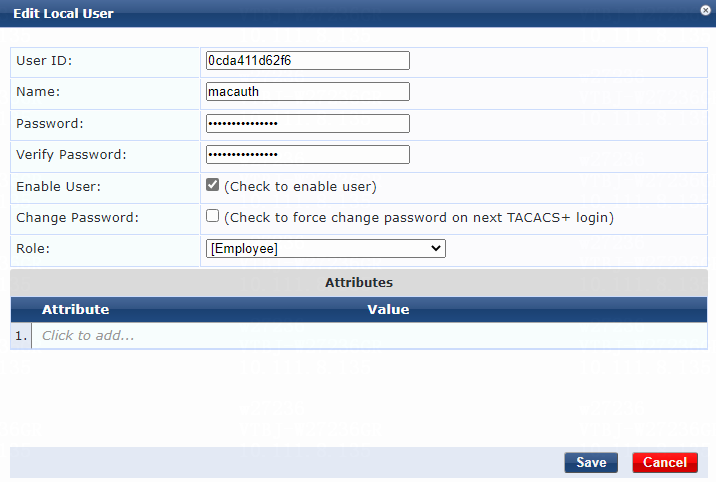
1. When you add the user account for the client, the user ID and password must be set to the MAC address of the client.
Figure 15 Adding a user
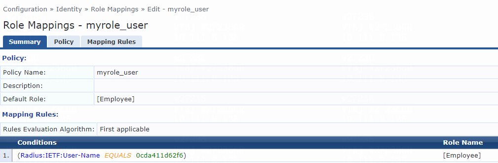
2. When you add the mapping rule for the client, enter the MAC address of the client in the Value field for the User-Name attribute.
Figure 16 Role mapping summary
Verifying the configuration
1. On the client, ping the ClearPass server to verify that you can pass MAC authentication and come online. (Details not shown.)
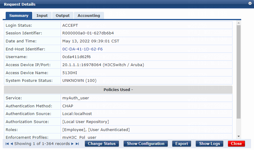
2. On the ClearPass server, view user access request details:
# From the left navigation pane, select Monitoring > Live Monitoring > Access Tracker.
# On the page that opens, view the access request record and verify that the client is online. To view details of the access request record, click the access request record.
Figure 17 Viewing access request details
3. On the switch, use the display mac-authentication connection command to display information about online MAC authentication users.
[Device]display mac-authentication connection
Total connections: 1
Slot ID: 1
User MAC address: 0cda-411d-62f6
Access interface: Ten-GigabitEthernet1/0/49
Username: 0cda411d62f6
User access state: Successful
Authentication domain: mac-auth
IPv4 address: 101.0.145.39
Initial VLAN: 144
Authorization untagged VLAN: N/A
Authorization tagged VLAN: N/A
Authorization ACL number/name: N/A
Authorization dynamic ACL name: N/A
Authorization user profile: N/A
Authorization CAR: N/A
Authorization URL: N/A
Termination action: Default
Session timeout period: N/A
Online from: 2022/05/13 09:39:01
Online duration: 0h 0m 6s
The output shows that the user has passed MAC authentication and is online.
Examples: Integrating the switch with ClearPass for 802.1X authentication
Network configuration
As shown in Figure 18, configure the switch to work in conjunction with a ClearPass server to do 802.1X authentication for the client connected to Ten-GigabitEthernet 1/0/49. The client must pass 802.1X authentication to access network resources.
Configure the switch as follows:
· Use the ClearPass server as the RADIUS server to perform 802.1X authentication for the client.
· Use PAP, CHAP, EAP-MD5, or certificate authentication (EAP-TLS, EAP-PEAP, or EAP-TTLS) for 802.1X authentication.

Software versions used
This configuration example was created and verified on the following hardware and software versions:
|
Hardware |
Software version |
|
H3C S5130-HI switch |
R3507P02 |
|
Aruba ClearPass server |
Aruba ClearPass Policy Manager (CPPM) v6.9.7 |
Example: Integrating the switch with ClearPass for 802.1X CHAP authentication
Prerequisites
This example provides only the configuration for authentication. Make sure that the client, switch, and server have network connectivity to communicate with one another.
Configuring the switch
# Create a RADIUS scheme named radius1, specify the ClearPass server at 20.1.1.3 for user authentication and accounting, set the shared key to 123456 in plaintext form, and exclude domain names from the usernames sent to the RADIUS server.
<Device> system-view
[Device] radius scheme radius1
[Device-radius-radius1] primary authentication 20.1.1.3
[Device-radius-radius1] primary accounting 20.1.1.3
[Device-radius-radius1] key authentication simple 123456
[Device-radius-radius1] key accounting simple 123456
[Device-radius-radius1] user-name-format without-domain
[Device-radius-radius1] quit
# Specify an authentication method. This example configures the switch to perform EAP termination and use CHAP to communicate with the RADIUS server.
[Device] dot1x authentication-method CHAP
# Create an ISP domain named bbb and apply the RADIUS scheme to the ISP domain for authentication, authorization, and accounting.
[Device] domain bbb
[Device-isp-bbb] authentication default radius-scheme radius1
[Device-isp-bbb] authorization lan-access radius-scheme radius1 local
[Device-isp-bbb] accounting lan-access radius-scheme radius1 local
[Device-isp-bbb] quit
# Create VLANs 144 and 145 and VLAN-interfaces 144 and 145, and assign IP addresses to the VLAN interfaces.
[Device] vlan 144
[Device-vlan144]quit
[Device] interface Vlan-interface 144
[Device-Vlan-interface144] ip address 101.0.145.19 255.255.255.0
[Device-Vlan-interface144] quit
[Device] vlan 145
[Device-vlan145] quit
[Device] interface Vlan-interface 145
[Device-Vlan-interface145] ip address 20.1.1.1 255.255.255.0
[Device-Vlan-interface145] quit
# Assign Ten-GigabitEthernet 1/0/49 to VLAN 144.
[Device]interface Ten-GigabitEthernet 1/0/49
[Device-Ten-GigabitEthernet1/0/49] port access vlan 144
# Enable 802.1X on Ten-GigabitEthernet 1/0/49 and specify ISP domain bbb as the mandatory domain.
[Device-Ten-GigabitEthernet1/0/49] dot1x
[Device-Ten-GigabitEthernet1/0/49] dot1x mandatory-domain bbb
# Enable port-based access control on Ten-GigabitEthernet 1/0/49.
[Device-Ten-GigabitEthernet1/0/49] dot1x port-method portbased
[Device-Ten-GigabitEthernet1/0/49] quit
# Assign Ten-GigabitEthernet 1/0/51 to VLAN 145.
[Device] interface Ten-GigabitEthernet 1/0/51
[Device-Ten-GigabitEthernet1/0/51] port access vlan 145
[Device-Ten-GigabitEthernet1/0/51] quit
# Specify ISP domain bbb as the default ISP domain.
[Device] domain default enable bbb
# Add a network access user named user, set the password to 123456 in plaintext form, and authorize the user to use the LAN access service.
[Device] local-user user class network
[Device-luser-network-user] password simple 123456
[Device-luser-network-user] service-type lan-access
[Device-luser-network-user] quit
# Enable 802.1X globally.
[Device] dot1x
Configuring the ClearPass server
1. Log in to the ClearPass server:
# Enter the management IP address of the ClearPass server in the address bar of the Web browser.
Figure 19 Logging in to ClearPass

# Click ClearPass Policy Manager.
# On the page that opens, enter the login username and password, and then click Log In. In this example, the username and password are admin and Pass1234_, respectively.
Figure 20 Logging in to ClearPass Policy Manager

2. Add a user:
# From the left navigation pane, select Configuration > Identity > Local Users.
# On the page that opens, click Add in the upper right corner.
# Configure the user account:
a. Set the user ID and name. In this example, user is used as both the user ID and name.
b. Set the password and then verify the password.
c. Select the Enable User option to enable the user account.
d. Select predefined role Employee or a user-defined role. In this example, predefined role Employee is selected.
e. Click Add.
Figure 21 Adding a user

3. Configure a role mapping:
# From the left navigation pane, select Configuration > Identity > Role Mappings.
# On the Policy tab, click Add in the upper right corner.
# Add a role mapping policy:
a. Specify the policy name. In this example, myrole_user is used.
b. Specify the default role as [Employee].
# Click Next to open the Mapping Rules tab, and then click Add Rule.
# On the page that opens, select the Select first match option for the Rules Evaluation Algorithm field and specify a mapping rule:
a. Select type Radius:IETF.
b. Select name User-Name.
c. Select operator EQUALS.
d. Enter the user ID you have specified in the Value field. In this example, the user ID is user.
e. Select role name [Employee].
f. Click Save.
Figure 22 Role mapping summary

4. Add the switch to ClearPass Policy Manager:
# From the left navigation pane, select Configuration > Network > Devices.
# On the page that opens, click Add in the upper right corner.
# Add the switch:
a. Specify the name of the switch. In this example, H3CSwitch is used.
b. Specify the IP address of the switch, for example, 20.1.1.1.
Make sure the ClearPass server can reach this IP address.
c. (Optional.) Enter a description of the switch for management purposes. In this example, 5130HI is used.
d. Configure the RADIUS shared secret and then verify the shared secret.
Make sure the shared secret specified on the server is the same as the shared key specified on the switch for 802.1X CHAP authentication. In this example, 123456 is used.
e. Select vendor name H3C.
f. Enable RADIUS dynamic authorization (the default port is 3799).
g. Click Add.
Figure 23 Adding a device

5. Add a device group:
# From the left navigation pane, select Configuration > Network > Device Groups.
# On the page that opens, click Add in the upper right corner.
# Configure the device group:
a. Specify the name of the device group. In this example, H3C_DevGroup4 is used.
b. (Optional.) Enter a description of the device group for management purposes. In this example, net is used.
c. Select format Subnet.
d. Specify a subnet in network_address/mask_length format (CIDR notation).
Make sure the ClearPass server can reach this subnet. In this example, 20.1.1.1/24 is used.
e. Click Save.
Figure 24 Adding a device group

6. Add an enforcement profile:
# From the left navigation pane, select Configuration > Enforcement > Profiles.
# On the page that opens, click Add in the upper right corner.
# Add the enforcement profile:
a. On the Profile tab, select RADIUS Based Enforcement in the Template field and set the name to myH3C_Pol_user.
b. (Optional.) Enter a description of the profile.
c. Set the action to Accept.
d. Select device group H3C_DevGroup4 from the device group drop-down list.
e. Click Next.
f. On the Attributes tab. select Radius:H3C from the type list, H3C-AVPair from the name list, and set the attribute value to shell:roles=network-admin.
g. Click Save.
Figure 25 Enforcement profile summary

7. Add an enforcement policy:
# From the left navigation pane, select Configuration > Enforcement > Policies.
# On the Enforcement tab, click Add in the upper right corner.
# Configure the policy:
a. Set the policy name to myH3CPolicy_user.
b. (Optional.) Enter a description of the enforcement policy for management purposes.
c. Select enforcement type RADIUS.
d. Select [Allow Access Profile] as the default profile.
# Click Next to open the Rules tab, and then click Add Rule.
# On the page that opens, select a rules evaluation algorithm for the Rules Evaluation Algorithm field. In this example, Select all matches is used. Then specify the following enforcement policy rules parameters:
a. Select type Tips.
b. Select name Role.
c. Select operator MATCHES_ALL.
d. Select value [Employee].
e. Select enforcement profile myH3C_Pol_user.
f. Click Save.
Figure 26 Enforcement policy summary
8. Add a service:
# From the left navigation pane, select Configuration > Services.
# On the page that opens, click Add in the upper right corner.
# On the Service tab, configure the service parameters:
a. Select RADIUS Enforcement (Generic) from the Type field.
b. Set the name to myAuth_user.
c. Select ALL of the following conditions for the Matches field.
d. Configure one rule to match Ethernet NAS ports. In the rule, set the type to Radius:IETF, name to NAS-Port-Type, operator to EQUALS, and value to Ethernet (15).
e. Configure another rule to match services. In the rule, set the type to Radius:IETF, name to Service-Type, operator to BELONGS_TO, and value to Login-User (1), Framed-User (2), and Authenticate-Only (8).
f. Click Save.
Figure 27 Adding a service
# On the Authentication tab, select [CHAP] from the Authentication Methods list and select [Local User Repository][Local SQL DB] from the Authentication Sources list.
Figure 28 Configuring authentication

# On the Roles tab, select myrole_user from the Role Mapping Policy list, and then click Save.
Figure 29 Configuring roles

# On the Enforcement tab, select enforcement policy myH3CPolicy_user, and then click Save.
Figure 30 Configuring enforcement

Verifying the configuration
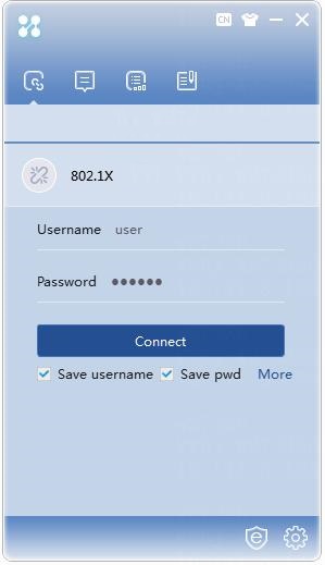
1. Use the iNode client to verify that you can pass 802.1X CHAP authentication to come online after you enter the username and password.
Figure 31 Logging in through the iNode client
2. On the ClearPass server, view user access request details:
# From the left navigation pane, select Monitoring > Live Monitoring > Access Tracker.
# On the page that opens, view the access request record and verify that the client is online. To view details of the access request record, click the access request record.
Figure 32 Viewing access request details

3. On the switch, use the display dot1x connection command to display information about online 802.1X CHAP authentication users.
[Device] display dot1x connection
Total connections: 1
Slot ID: 1
User MAC address: 0cda-411d-62f6
Access interface: Ten-GigabitEthernet1/0/49
Username: user
User access state: Successful
Authentication domain: bbb
Authentication method: CHAP
Initial VLAN: 144
Authorization untagged VLAN: N/A
Authorization tagged VLAN list: N/A
Authorization ACL number/name: N/A
Authorization dynamic ACL name: N/A
Authorization user profile: N/A
Authorization CAR: N/A
Authorization URL: N/A
Termination action: Default
Session timeout period: N/A
Online from: 2022/05/11 18:21:58
Online duration: 0h 1m 22s
The output shows that the user has passed 802.1X CHAP authentication and is online.
Example: Integrating the switch with ClearPass for 802.1X PAP authentication
Configuring the switch
Configure the switch as described in "Example: Integrating the switch with ClearPass for 802.1X CHAP authentication," except that you must set the authentication method to PAP, as follows:
[Device] dot1x authentication-method PAP
Configuring the ClearPass server
Configure the ClearPass server as described in "Example: Integrating the switch with ClearPass for 802.1X CHAP authentication," except that you must use the following settings in this example:
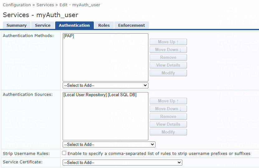
# On the Authentication tab, select [PAP] from the Authentication Methods list for the service.
Figure 33 Configuring authentication
Verifying the configuration
1. Use the iNode client to verify that you can pass 802.1X PAP authentication to come online after you enter the username and password. (Details not shown.)
2. On the ClearPass server, view user access request details:
# From the left navigation pane, select Monitoring > Live Monitoring > Access Tracker.
# On the page that opens, view the access request record and verify that the client is online. To view details of the access request record, click the access request record.
Figure 34 Viewing access request details
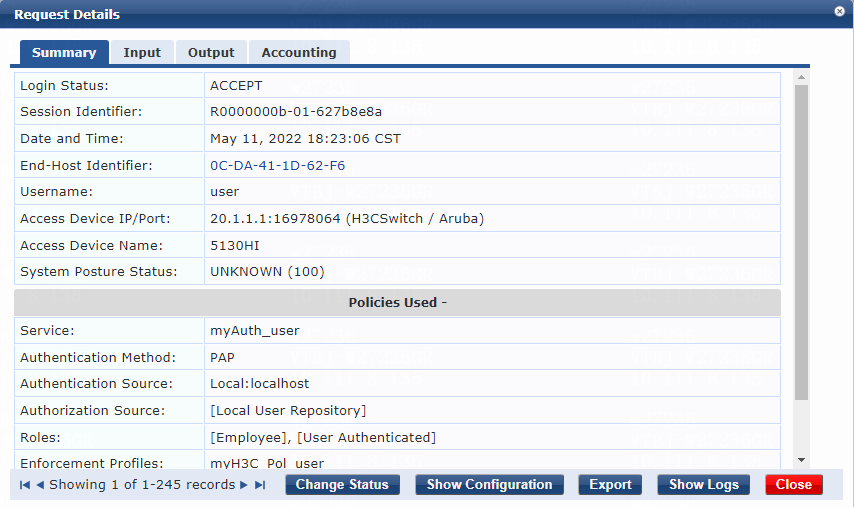
3. On the switch, use the display dot1x connection command to display information about online 802.1X PAP authentication users.
[Device]display dot1x connection
Total connections: 1
Slot ID: 1
User MAC address: 0cda-411d-62f6
Access interface: Ten-GigabitEthernet1/0/49
Username: user
User access state: Successful
Authentication domain: bbb
Authentication method: PAP
Initial VLAN: 144
Authorization untagged VLAN: N/A
Authorization tagged VLAN list: N/A
Authorization ACL number/name: N/A
Authorization dynamic ACL name: N/A
Authorization user profile: N/A
Authorization CAR: N/A
Authorization URL: N/A
Termination action: Default
Session timeout period: N/A
Online from: 2022/05/11 18:23:06
Online duration: 0h 4m 28s
The output shows that the user has passed 802.1X PAP authentication and is online.
Example: Integrating the switch with ClearPass for 802.1X EAP-MD5 authentication
Configuring the switch
Configure the switch as described in "Example: Integrating the switch with ClearPass for 802.1X CHAP authentication," except that you must set the authentication method to EAP, as follows:
[Device] dot1x authentication-method EAP
Configuring the ClearPass server
Configure the ClearPass server as described in "Example: Integrating the switch with ClearPass for 802.1X CHAP authentication," except that you must use the following settings in this example:
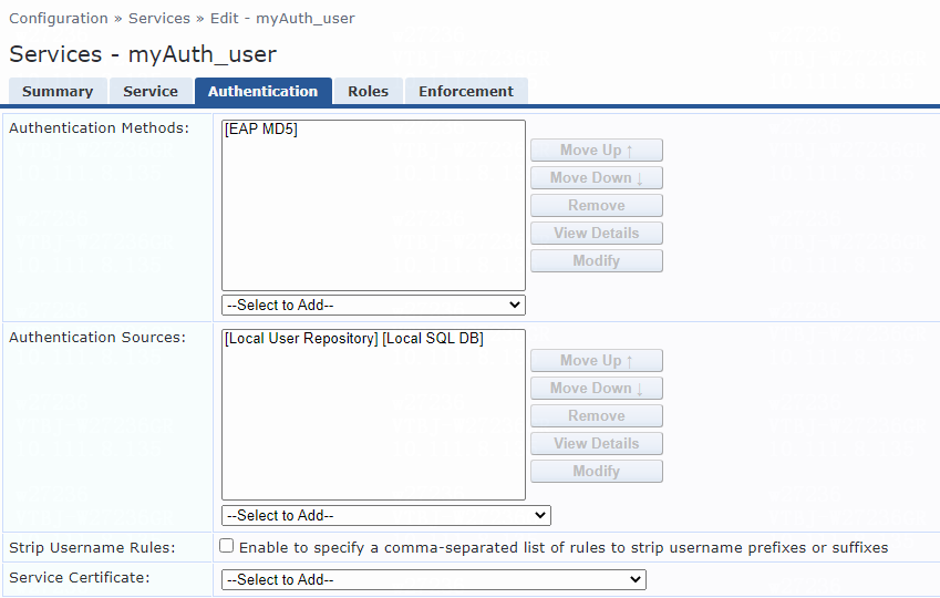
# On the Authentication tab, select [EAP MD5] from the Authentication Methods list for the service.
Figure 35 Configuring authentication
Verifying the configuration
1. Use the iNode client to verify that you can pass 802.1X EAP-MD5 authentication to come online after you enter the username and password. (Details not shown.)
2. On the ClearPass server, view user access request details:
# From the left navigation pane, select Monitoring > Live Monitoring > Access Tracker.
# On the page that opens, view the access request record and verify that the client is online. To view details of the access request record, click the access request record.
Figure 36 Viewing access request details
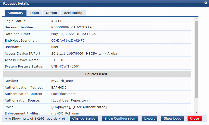
3. On the switch, use the display dot1x connection command to display information about online 802.1X EAP-MD5 authentication users.
[Device] display dot1x connection
Total connections: 1
Slot ID: 1
User MAC address: 0cda-411d-62f6
Access interface: Ten-GigabitEthernet1/0/49
Username: user
User access state: Successful
Authentication domain: bbb
Authentication method: EAP
Initial VLAN: 144
Authorization untagged VLAN: N/A
Authorization tagged VLAN list: N/A
Authorization ACL number/name: N/A
Authorization dynamic ACL name: N/A
Authorization user profile: N/A
Authorization CAR: N/A
Authorization URL: N/A
Termination action: Default
Session timeout period: N/A
Online from: 2022/05/11 18:34:37
Online duration: 0h 0m 4s
The output shows that the user has passed 802.1X EAP-MD5 authentication and is online.
Example: Integrating the switch with ClearPass for 802.1X certificate authentication
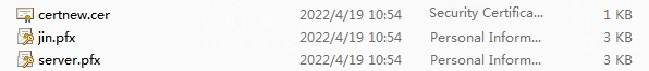
To perform ClearPass-based 802.1X certificate authentication, you must import the required certificates into the iNode client and the ClearPass server, and select the same authentication method on the client, switch, and server. To obtain the certificates, contact the technical support. In this example, root certificate certnew.cer, client certificate jin.pfx, and server certificate server.pfx are used.
Figure 37 Certificates used for 802.1X certificate authentication
Configuring the client
1. Import root certificate certnew.cer to the client:
a. Copy the root certificate to the installation path of the iNode client. In this example, the installation path is C:\Program Files (x86)\iNode\iNode Client.
b. Double click file certnew.cer to open the installation window.
c. Click Install Certificate….
d. On the Certificate Import Wizard that opens, click Next.
e. Select Place All Certificates in the Following Store and click Browse.
f. Select Trusted Root Certification Authorities, and then click OK.
g. Click Next.
h. Click Finish.
2. Import client certificate jin.pfx to the client:
a. Copy the client certificate to the installation path of the iNode client.
b. Double click file jin.pfx to open the installation window.
c. Click Next.
d. Click Next (Use the default path).
e. Enter the password you entered when you downloaded the certificate. Select the Include all extended properties option and click Next.
f. Select Automatically select the certificate store based on the type to certificate and click Next.
g. Click Finish.
3. Configure the authentication method on the iNode client:
a. Open the iNode client and access the 802.1X connection page.
b. Click More > Properties to open the 802.1X Authentication page.
Figure 38 802.1X Authentication page

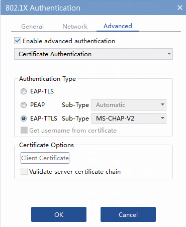
c. Click Advanced. Enable advanced authentication and select one of the following 802.1X authentication types:
- Select EAP-TLS for 802.1X EAP-TLS authentication.
- Select PEAP for 802.1X EAP-PEAP authentication.
- Select EAP-TTLS and subtype MS-CHAP-V2 for 802.1X EAP-TTLS authentication.
Figure 39 Configuring 802.1X EAP-TLS authentication
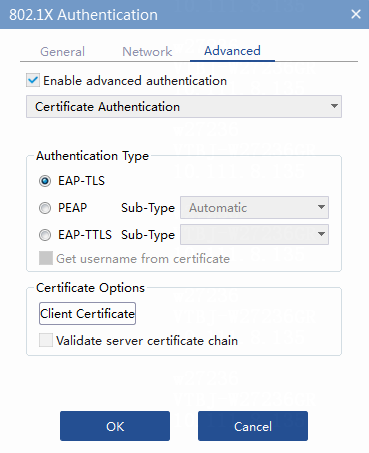
Figure 40 Configuring 802.1X EAP-PEAP authentication
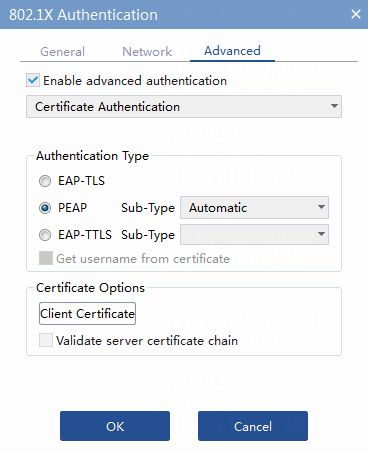
Figure 41 Configuring 802.1X EAP-TTLS authentication
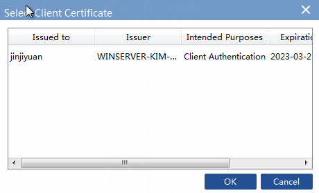
d. Click Client Certificate in the Certificate Options area. On the Select Client Certificate page that opens, select the imported client certificate, and then click OK.
Figure 42 Selecting client certificate
Configuring the switch
Configure the switch as described in "Example: Integrating the switch with ClearPass for 802.1X CHAP authentication," except that you must set the authentication method to EAP:
[Device] dot1x authentication-method EAP
Configuring the ClearPass server
Configure the ClearPass server as described in "Example: Integrating the switch with ClearPass for 802.1X CHAP authentication," except that you must use the following settings in this example:
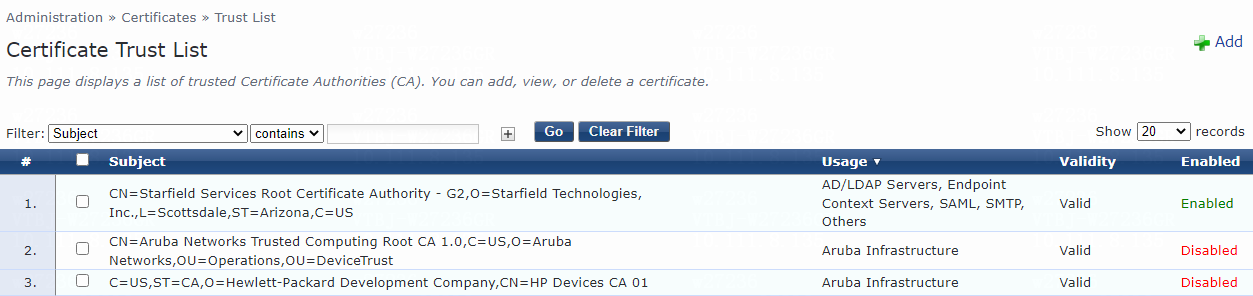
1. Import root certificate certnew.cer to the server:
a. Navigate to the Administration > Certificates > Trust List page.
Figure 43 Certificate Trust List page
b. Click Add.
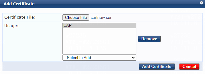
c. On the Add Certificate page that opens, click Choose File.
d. Select root certificate certnew.cer, select EAP from the Usage list, and then click Add Certificate.
Figure 44 Adding the root certificate
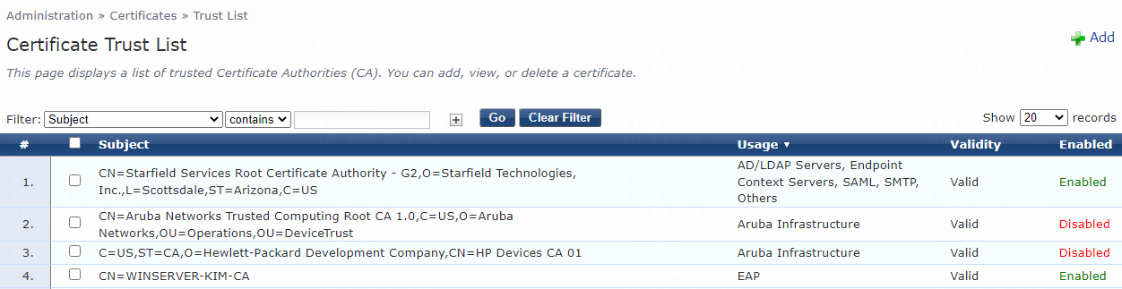
e. View the added certificate.
The root certificate with the CN=WINSERVER-KIM-CA subject has been successfully added.
Figure 45 Viewing the certificate
2. Import server certificate server.pfx to the server:
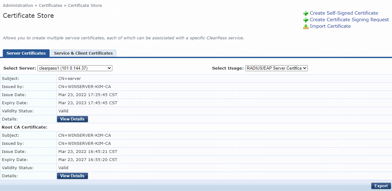
a. Navigate to the Administration > Certificates > Certificate Store page.
Figure 46 Certificate Store page
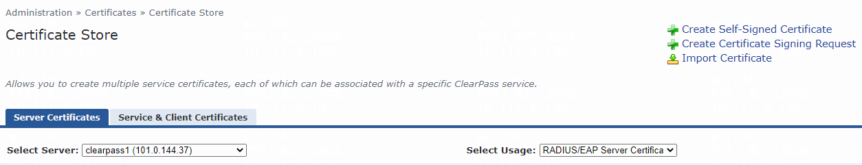
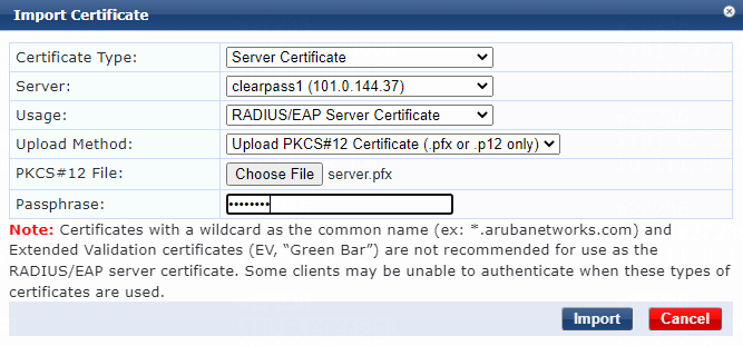
b. On the Server Certificates tab, click Import Certificate.
c. On the Import Certificate page that opens, specify the following parameters:
- Select the target ClearPass server from the Server list. In this example, clearpass1 (101.0.144.37) is selected.
- Select RADIUS/EAP Server Certificate from the Usage list.
- Select Upload PKCS#12 Certificate (.pfx or .p12 only) from the Upload Method list.
d. Click Choose File.
e. Select server certificate server.pfx.
f. Enter the passphrase.
g. Click Import.
Figure 47 Importing the server certificate
h. View the added certificate.
The server certificate with the CN=server subject has been successfully added.
Figure 48 Viewing the certificate
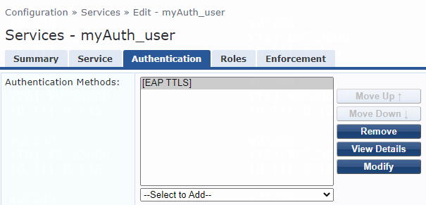
3. On the Authentication tab, select [EAP TLS], [EAP PEAP], or [EAP TTLS] from the Authentication Methods list for the service.
Figure 49 Configuring EAP-TLS authentication
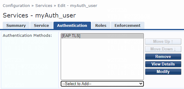
Figure 50 Configuring EAP-PEAP authentication
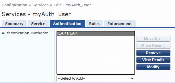
Figure 51 Configuring EAP-TTLS authentication
Verifying the configuration
1. Use the iNode client to verify that you can pass 802.1X EAP-TLS, EAP-PEAP, or EAP-TTLS authentication to come online after you enter the username and password. (Details not shown.)
2. On the ClearPass server, view user access request details:
# From the left navigation pane, select Monitoring > Live Monitoring > Access Tracker.
# On the page that opens, view the access request record and verify that the client is online. To view details of the access request record, click the access request record.
Figure 52 Viewing 802.1X EAP-TLS authentication online users
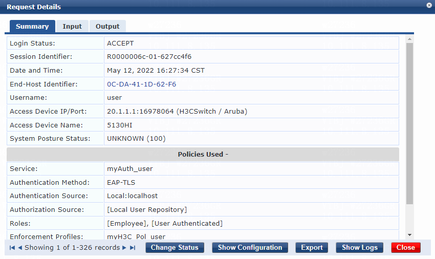
Figure 53 Viewing 802.1X EAP-PEAP authentication online users
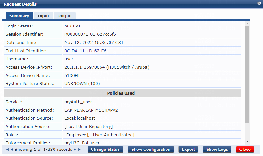
Figure 54 Viewing 802.1X EAP-TTLS authentication online users
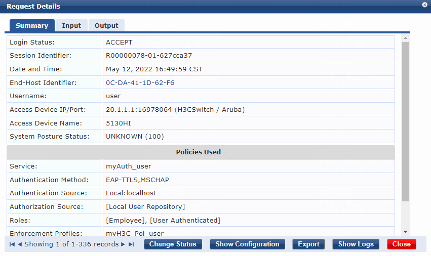
3. On the switch, use the display dot1x connection command to display information about online 802.1X EAP-TLS, EAP-PEAP, or EAP-TTLS authentication users. In this example, 802.1X EAP-TTLS authentication is used.
[Device]display dot1x connection
Total connections: 1
Slot ID: 1
User MAC address: 0cda-411d-62f6
Access interface: Ten-GigabitEthernet1/0/49
Username: user
User access state: Successful
Authentication domain: bbb
Authentication method: EAP
Initial VLAN: 144
Authorization untagged VLAN: N/A
Authorization tagged VLAN list: N/A
Authorization ACL number/name: N/A
Authorization dynamic ACL name: N/A
Authorization user profile: N/A
Authorization CAR: N/A
Authorization URL: N/A
Termination action: Default
Session timeout period: N/A
Online from: 2022/05/12 16:49:59
Online duration: 0h 0m 5s
The output shows that the user has passed 802.1X EAP-TTLS authentication and is online.
Example: Integrating the switch with ClearPass for portal authentication
Network configuration
As shown in Figure 55, configure the switch to work in conjunction with a ClearPass server to do portal authentication for the client connected to Ten-GigabitEthernet 1/0/49. The client must pass portal authentication to access network resources.
Configure the switch as follows:
· Use the ClearPass server as the RADIUS server and portal authentication server to perform portal authentication for the client.
· Use direct portal authentication.
Software versions used
This configuration example was created and verified on the following hardware and software versions:
|
Hardware |
Software version |
|
H3C S5130-HI switch |
R3507P02 |
|
Aruba ClearPass server |
Aruba ClearPass Policy Manager (CPPM) v6.9.7 |
Procedures
Prerequisites
This example provides only the configuration for authentication. Make sure that the client, switch, and server have network connectivity to communicate with one another.
Configuring the switch
# Import security certificates cacert.crt and local.pfx into the switch through FTP for configuring HTTPS connection.
To obtain the certificates, contact the technical support.
Figure 56 Certificates for configuring HTTPS connections
![]()
# Create a RADIUS scheme named radius1, specify the ClearPass server at 20.1.1.3 for user authentication and accounting, set the shared key to 123456 in plaintext form, and exclude domain names from the usernames sent to the RADIUS server.
<Device> system-view
[Device] radius scheme radius1
[Device-radius-radius1] primary authentication 20.1.1.3
[Device-radius-radius1] primary accounting 20.1.1.3
[Device-radius-radius1] key authentication simple 123456
[Device-radius-radius1] key accounting simple 123456
[Device-radius-radius1] user-name-format without-domain
[Device-radius-radius1] quit
# Create an ISP domain named dm1 and apply the RADIUS scheme to the ISP domain for authentication, authorization, and accounting.
[Device] domain dm1
[Device-isp-dm1] authentication portal radius-scheme radius1
[Device-isp-dm1] authorization portal radius-scheme radius1
[Device-isp-dm1] accounting portal radius-scheme radius1
[Device-isp-dm1]quit
# Create VLAN 144 and VLAN-interface 144, and assign an IP address to the VLAN interface.
[Device] vlan 144
[Device-vlan144] quit
[Device] interface Vlan-interface 144
[Device-Vlan-interface144] ip address 101.0.145.19 255.255.255.0
# Specify portal Web server newpt on VLAN-interface 144.
[Device-Vlan-interface144] portal apply web-server newpt
# Configure the BAS-IP as 101.0.145.19 for portal packets sent from VLAN-interface 144 to the portal authentication server.
[Device-Vlan-interface144] portal bas-ip 101.0.145.19
[Device-Vlan-interface144]quit
# Create VLAN 145 and VLAN-interface 145, and then assign an IP address to the VLAN interface.
[Device] vlan 145
[Device-vlan145] quit
[Device] interface Vlan-interface 145
[Device-Vlan-interface145] ip address 20.1.1.1 255.255.255.0
[Device-Vlan-interface145] quit
# Assign Ten-GigabitEthernet 1/0/49 to VLAN 144 and Ten-GigabitEthernet 1/0/51 to VLAN 145.
[Device] interface Ten-GigabitEthernet 1/0/49
[Device-Ten-GigabitEthernet1/0/49] port access vlan 144
[Device-Ten-GigabitEthernet1/0/49] quit
[Device] interface Ten-GigabitEthernet 1/0/51
[Device-Ten-GigabitEthernet1/0/51] port access vlan 145
[Device-Ten-GigabitEthernet1/0/51] quit
# Specify ISP domain dm1 as the default ISP domain.
[Device] domain default enable dm1
# Create a PKI domain named sslvpn and specify general purpose RSA key pair sslvpn for certificate requests.
[Device] pki domain sslvpn
[Device-pki-domain-sslvpn] public-key rsa general name sslvpn
# Disable CRL checking.
[Device-pki-domain-sslvpn] undo crl check enable
[Device-pki-domain-sslvpn] quit
|
|
IMPORTANT: When CRL checking is enabled, a certificate request will fail if the certificate has been revoked, a CRL does not exist in the PKI domain, or the device fails to obtain a CRL. |
# Import CA certificate file cacert.crt in PEM format and local certificate file local.pfx in PKCS12 format to PKI domain sslvpn. Enter the password you entered when you downloaded the certificate.
[Device] pki import domain sslvpn pem ca filename cacert.crt
[Device] pki import domain sslvpn p12 local filename local.pfx
# Create an SSL server policy named 1 for the HTTPS service.
[Device] ssl server-policy 1
[Device-ssl-server-policy-1] pki-domain sslvpn
# Configure an IP-based portal-free rule: specify the rule number as 2 and destination IP address as 101.0.145.19 255.255.255.255.
[Device] portal free-rule 2 destination ip 101.0.145.19 255.255.255.255
# Specify a URL for portal Web server newpt.
[Device] portal web-server newpt
[Device-portal-websvr-newpt] url https://20.1.1.3/guest/h3c.php?_browser=1
[Device-portal-websvr-newpt] quit
# Configure the portal authentication server.
[Device] portal server newpt
[Device-portal-server-newpt] ip 20.1.1.3 key simple 123456
[Device-portal-server-newpt] quit
# Create an HTTPS-based local portal Web service, and configure the HTTPS service to use SSL server policy 1 and HTTPS listening port number 8443.
[Device] portal local-web-server https ssl-server-policy 1 tcp-port 8443
# Specify file defaultfile.zip as the default authentication page file for the local portal Web service.
[Device-portal-local-websvr-https] default-logon-page defaultfile.zip
[Device-portal-local-websvr-https] quit
# Enable the HTTPS service.
[Device] ip https enable
|
|
IMPORTANT: When you use Aruba ClearPass as a portal Web server, you must specify HTTPS to access its URL. |
# Enable direct portal authentication on VLAN-interface 144.
[Device] interface Vlan-interface 144
[Device-Vlan-interface144] portal enable method direct
[Device-Vlan-interface144] quit
|
|
NOTE: A user can use direct portal authentication or cross-subnet portal authentication to come online. To do cross-subnet portal authentication, replace the portal enable method direct command with the portal enable method layer3 command on the switch. No configuration change is required on the server and client. |
Configuring the ClearPass server
1. Log in to the ClearPass server:
# Enter the management IP address of the ClearPass server in the address bar of the Web browser.
Figure 57 Logging in to ClearPass
# Click ClearPass Guest.
2. Create a Web login page:
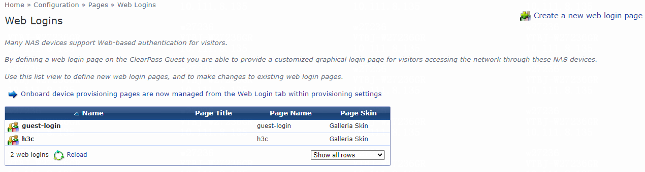
# From the left navigation pane, select Configuration > Pages > Web Logins.
# On the page that opens, click Create a new web login page in the upper right corner.
Figure 58 Creating a Web login page
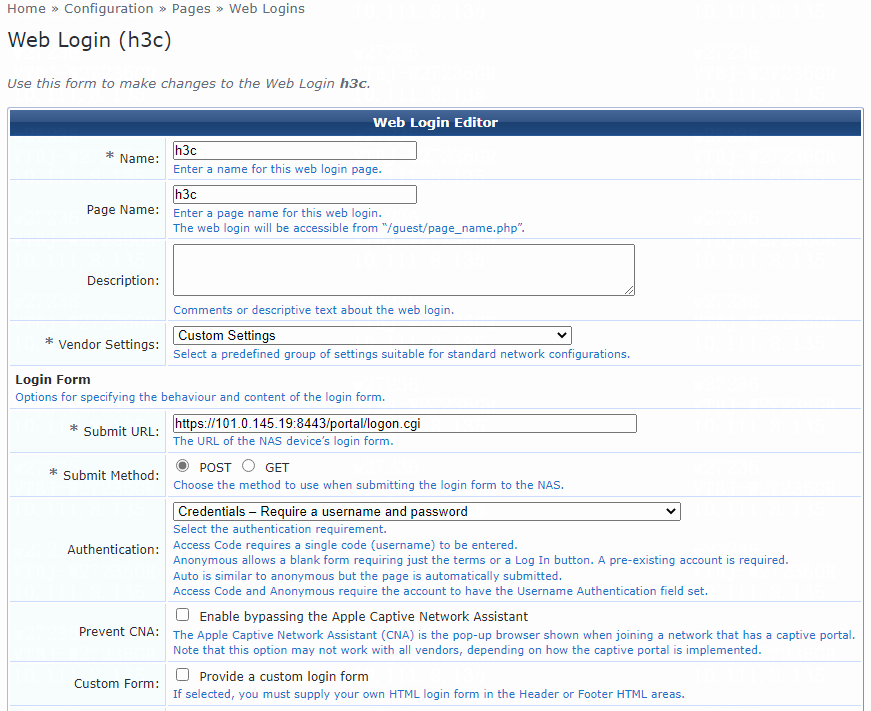
# Configure the Web login page parameters:
a. Set the name and page name for the Web login page. In this example, h3c is used.
b. Specify the vendor settings. In this example, Custom Settings is used.
c. Enter https://101.0.145.19:8443/portal/logon.cgi in the Submit URL field.
The access service must be HTTPS, the IP address must be the IP address of the interface on which portal authentication is enabled, and the port number (8443) must be the same as that configured on the switch.
d. Set Submit Method to POST.
Figure 59 Specifying Web login page parameters
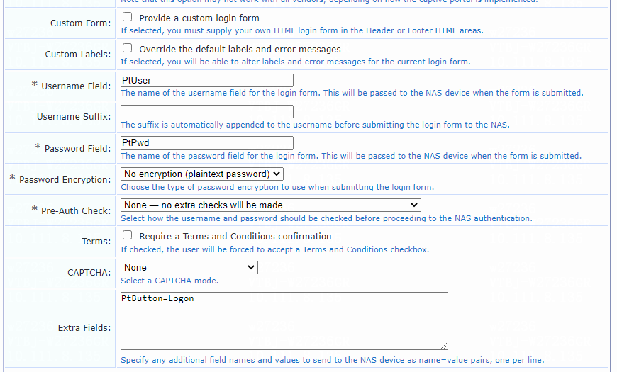
e. Enter PtUser in the Username Field field, PtPwd in the Password Field field, and PtButton=Logon in the Extra Fields field.
As a best practice, do not change the settings for the Username Field, Password Field, and Extra Fields fields.
f. Select None — no extra checks will be made for the Pre-Auth Check field.
g. Use the default values for other parameters.
h. Click Save Changes.
Figure 60 Specifying Web login page parameters
3. Log in to ClearPass Policy Manager:
# Enter the management IP address of the ClearPass server in the address bar of the Web browser.
Figure 61 Logging in to ClearPass
# Click ClearPass Policy Manager.
# On the page that opens, enter the login username and password, and then click Log In. In this example, the username and password are admin and Pass1234_, respectively.
Figure 62 Logging in to ClearPass Policy Manager

4. Add a user:
# From the left navigation pane, select Configuration > Identity > Local Users.
# On the page that opens, click Add in the upper right corner.
# Configure the user account:
a. Set the user ID and name. In this example, user is used as both the user ID and name.
b. Set the password and then verify the password.
c. Select the Enable User option to enable the user account.
d. Select predefined role Employee or a user-defined role. In this example, predefined role Employee is selected.
e. Click Add.
Figure 63 Adding a user
5. Configure a role mapping:
# From the left navigation pane, select Configuration > Identity > Role Mappings.
# On the Policy tab, click Add in the upper right corner.
# Add a role mapping policy:
a. Specify the policy name. In this example, myrole_user is used.
b. Specify the default role as [Employee].
# Click Next to open the Mapping Rules tab, and then click Add Rule.
# On the page that opens, select the Select first match option for the Rules Evaluation Algorithm field and specify a mapping rule:
a. Select type Radius:IETF.
b. Select name User-Name.
c. Select operator EQUALS.
d. Enter the user ID you have specified in the Value field. In this example, the user ID is user.
e. Select role name [Employee].
f. Click Save.
Figure 64 Role mapping summary
6. Add the switch to ClearPass Policy Manager:
# From the left navigation pane, select Configuration > Network > Devices. On the page that opens, click Add in the upper right corner.
# Add the switch:
a. Specify the name of the switch. In this example, H3CSwitch is used.
b. Specify the IP address of the switch, for example, 20.1.1.1.
Make sure the ClearPass server can reach this IP address.
c. (Optional.) Enter a description of the switch for management purposes. In this example, 5130HI is used.
d. Configure the RADIUS shared secret and then verify the shared secret.
Make sure the shared secret specified on the server is the same as the shared key specified on the switch. In this example, 123456 is used.
e. Select vendor name H3C.
f. Enable RADIUS dynamic authorization (the default port is 3799).
g. Click Add.
Figure 65 Adding a device
7. Add a device group:
# From the left navigation pane, select Configuration > Network > Device Groups.
# On the page that opens, click Add in the upper right corner.
# Configure the device group:
a. Specify the name of the device group. In this example, H3C_DevGroup4 is used.
b. (Optional.) Enter a description of the device group for management purposes. In this example, net is used.
c. Select format Subnet.
d. Specify a subnet in network_address/mask_length format (CIDR notation).
Make sure the ClearPass server can reach this subnet. In this example, 20.1.1.1/24 is used.
e. Click Save.
Figure 66 Adding a device group
8. Add an enforcement profile:
# From the left navigation pane, select Configuration > Enforcement > Profiles.
# On the page that opens, click Add in the upper right corner.
# Configure the enforcement profile:
a. On the Profile tab, select RADIUS Based Enforcement in the Template field and set the name to myH3C_Pol_user.
b. (Optional.) Enter a description of the profile.
c. Set the action to Accept.
d. Select device group H3C_DevGroup4 from the device group list.
e. Click Next.
f. On the Attributes tab, select Radius:H3C from the type list, H3C-AVPair from the name list, and set the attribute value to shell:roles=network-admin.
g. Click Save.
Figure 67 Enforcement profile summary
9. Add an enforcement policy:
# From the left navigation pane, select Configuration > Enforcement > Policies.
# On the Enforcement tab, click Add in the upper right corner.
# Configure the policy:
a. Set the policy name to myH3CPolicy_user.
b. (Optional.) Enter a description of the enforcement policy for management purposes.
c. Select enforcement type RADIUS.
d. Select [Allow Access Profile] as the default profile.
# Click Next to open the Rules tab, and then click Add Rule.
# On the page that opens, select a rules evaluation algorithm for the Rules Evaluation Algorithm field. In this example, Select all matches is used. Then specify the following enforcement policy rules parameters:
a. Select type Tips.
b. Select name Role.
c. Select operator MATCHES_ALL.
d. Select value [Employee].
e. Select enforcement profile myH3C_Pol_user.
f. Click Save.
Figure 68 Enforcement policy summary
10. Add a service:
# From the left navigation pane, select Configuration > Services.
# On the page that opens, click Add in the upper right corner.
# On the Service tab, configure the service parameters:
a. Select RADIUS Enforcement (Generic) from the Type field.
b. Set the name to myAuth_user.
c. Select ALL of the following conditions for the Matches field.
d. Configure the first rule. In the rule, set the type to Radius:IETF, name to NAS-Port-Type, operator to EQUALS, and value to Ethernet (15).
e. Configure the second rule. In the rule, set the type to Radius:IETF, name to Service-Type, operator to BELONGS_TO, and value to Login-User (1), Framed-User (2), and Authenticate-Only (8).
f. Configure the third rule. In the rule, set the type to Radius:IETF, name to Framed-Protocol, operator to BELONGS_TO, and value to Portal (255).
g. Click Save.
Figure 69 Adding a service
# On the Authentication tab, select [PAP] from the Authentication Methods list and select [Local User Repository][Local SQL DB] from the Authentication Sources list.
Figure 70 Configuring authentication
# On the Roles tab, select myrole_user from the Role Mapping Policy list, and then click Save.
Figure 71 Configuring roles

# On the Enforcement tab, select enforcement policy myH3CPolicy_user, and then click Save.
Figure 72 Configuring enforcement
Verifying the configuration
1. On the client, open a Web browser and enter a random IP address in the address bar. Verify that you are redirected to the Web login page specified on the server.
Figure 73 Web login page
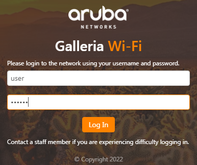
2. Enter the username and password of the user account configured on the server, and then click Log In. Verify that you can pass authentication to access the network.
3. On the ClearPass server, view user access request details:
# From the left navigation pane, select Monitoring > Live Monitoring > Access Tracker.
# On the page that opens, view the access request record and verify that the client has passed portal authentication and come online. To view details of the access request record, click the access request record.
Figure 74 Viewing access request details
4. On the switch, use the display portal user command to display information about portal users.
[Device] display portal user all
Total portal users: 1
Username: user
Portal server:
State: Online
VPN instance: N/A
MAC IP VLAN Interface
0cda-411d-62f6 101.0.145.39 144 Vlan-interface144
Authorization information:
DHCP IP pool: N/A
User profile: N/A
Session group profile: N/A
ACL number: N/A
Inbound CAR: N/A
Outbound CAR: N/A
The output shows that the user has passed portal authentication and is online.
Examples: Integrating the switch with ClearPass for 802.1X or MAC authentication with VLAN assignment
Network configuration
As shown in Figure 75, configure the switch to work in conjunction with a ClearPass server to do 802.1X or MAC authentication for the client connected to Ten-GigabitEthernet 1/0/49. The client must pass 802.1X or MAC authentication to access network resources.
Configure the switch as follows:
· Use the ClearPass server as the RADIUS server to perform 802.1X or MAC authentication for the client.
· Configure the ClearPass server to assign an authorization VLAN to the client after the client passes 802.1X or MAC authentication. The initial VLAN is 144.

Software versions used
This configuration example was created and verified on the following hardware and software versions:
|
Hardware |
Software version |
|
H3C S5130-HI switch |
R3507P02 |
|
Aruba ClearPass server |
Aruba ClearPass Policy Manager (CPPM) v6.9.7 |
Example: Integrating the switch with ClearPass for 802.1X or MAC authentication with VLAN ID assignment
Configuring the switch
For MAC authentication users, configure the switch as described in "Example: Integrating the switch with ClearPass for MAC authentication with a shared user account."
For 802.1X authentication users, configure the switch as described in "Example: Integrating the switch with ClearPass for 802.1X CHAP authentication."
Configuring the ClearPass server
Configure the ClearPass server for MAC authentication users as described in "Example: Integrating the switch with ClearPass for MAC authentication with a shared user account."
Configure the ClearPass server for 802.1X users as described in "Example: Integrating the switch with ClearPass for 802.1X CHAP authentication."
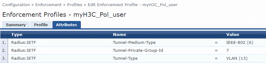
For VLAN assignment, you must modify the attribute settings on the Attributes tab for the enforcement profile, as follows:
· Specify the tunnel medium type. Select Radius:IETF from the type list, select Tunnel-Medium-Type from the name list, and set the attribute value to IEEE-802 (6).
A value of 6 indicates that the tunnel medium type is 802, which supports VLAN assignment.
· Specify the VLAN ID to be assigned. Select Radius:IETF from the type list, select Tunnel-Private-Group-Id from the name list, and set the attribute value. For example, set the attribute value to 7.
· Specify the type of the value in the Tunnel-Private-Group-Id attribute field. For VLAN assignment, select Radius:IETF from the type list, select Tunnel-Type from the name list, and set the attribute value to VLAN (13).
Figure 76 Specifying attribute parameters in the enforcement profile
Verifying the configuration
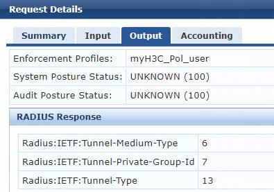
1. On the ClearPass server, view user access request details:
# From the left navigation pane, select Monitoring > Live Monitoring > Access Tracker.
# On the page that opens, view the access request record and verify that the client has passed 802.1X or MAC authentication and come online. To view details of the access request record, click the access request record.
Figure 77 Viewing access request details
2. On the switch, verify that the 802.1X or MAC authentication user is correctly assigned the specified authorization VLAN ID.
# Use the display dot1x connection command to display information about online 802.1X authentication users.
[Device]display dot1x connection
Total connections: 1
Slot ID: 1
User MAC address: 0cda-411d-62f6
Access interface: Ten-GigabitEthernet1/0/49
Username: user
User access state: Successful
Authentication domain: bbb
Authentication method: EAP
Initial VLAN: 144
Authorization untagged VLAN: 7
Authorization tagged VLAN list: N/A
Authorization ACL number/name: N/A
Authorization dynamic ACL name: N/A
Authorization user profile: N/A
Authorization CAR: N/A
Authorization URL: N/A
Termination action: Default
Session timeout period: N/A
Online from: 2022/05/11 18:42:15
Online duration: 0h 0m 45s
# Use the display mac-authentication connection command to display information about online MAC authentication users.
[Device]display mac-authentication connection
Total connections: 1
Slot ID: 1
User MAC address: 0cda-411d-62f6
Access interface: Ten-GigabitEthernet1/0/49
Username: user
User access state: Successful
Authentication domain: mac-auth
IPv4 address: 101.0.145.39
Initial VLAN: 144
Authorization untagged VLAN: 7
Authorization tagged VLAN: N/A
Authorization ACL number/name: N/A
Authorization dynamic ACL name: N/A
Authorization user profile: N/A
Authorization CAR: N/A
Authorization URL: N/A
Termination action: Default
Session timeout period: N/A
Online from: 2022/05/13 10:06:50
Online duration: 0h 0m 16s
The output shows that VLAN 7 has been successfully assigned to the user.
Example: Integrating the switch with ClearPass for 802.1X or MAC authentication with VLAN name assignment
When you use a remote server to assign named authorization VLANs to users, you must create the VLANs and specify their names on the switch. This configuration is required for the switch to map the named authorization VLANs received from the server to their VLAN IDs.
Configuring the switch
1. Configure basic authentication settings:
¡ For MAC authentication users, configure the switch as described in "Example: Integrating the switch with ClearPass for MAC authentication with a shared user account."
¡ For 802.1X authentication users, configure the switch as described in "Example: Integrating the switch with ClearPass for 802.1X CHAP authentication."
2. Create an authorization VLAN and assign a name to it. In this example, create VLAN 8 and set its name to vl.
[Device] vlan 8
[Device-vlan8] name vl
Configuring the ClearPass server
Configure basic settings:
· Configure the ClearPass server for MAC authentication users as described in "Example: Integrating the switch with ClearPass for MAC authentication with a shared user account."
· Configure the ClearPass server for 802.1X users as described in "Example: Integrating the switch with ClearPass for 802.1X CHAP authentication."
For named VLAN assignment, you must modify the attribute settings on the Attributes tab for the enforcement profile, as follows:
· Specify the tunnel medium type. Select Radius:IETF from the type list, select Tunnel-Medium-Type from the name list, and set the attribute value to IEEE-802 (6).
A value of 6 indicates that the tunnel medium type is 802, which supports VLAN assignment.
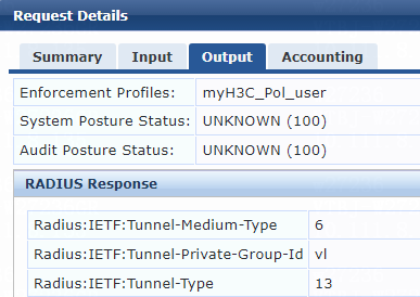
· Specify the VLAN name to be assigned. Select Radius:IETF from the type list, select Tunnel-Private-Group-Id from the name list, and set the attribute value. For example, set the attribute value to vl.
· Specify the type of the value in the Tunnel-Private-Group-Id attribute field. For VLAN assignment, select Radius:IETF from the type list, select Tunnel-Type from the name list, and set the attribute value to VLAN (13).
Figure 78 Specifying attribute parameters in the enforcement profile

Verifying the configuration
1. On the ClearPass server, view user access request details:
# From the left navigation pane, select Monitoring > Live Monitoring > Access Tracker.
# On the page that opens, view the access request record and verify that the client has passed 802.1X or MAC authentication and come online. To view details of the access request record, click the access request record.
Figure 79 Viewing access request details
2. On the switch, verify that the 802.1X or MAC authentication user is correctly assigned the named authorization VLAN.
# Use the display dot1x connection command to display information about online 802.1X authentication users.
[Device] display dot1x connection
Total connections: 1
Slot ID: 1
User MAC address: 0cda-411d-62f6
Access interface: Ten-GigabitEthernet1/0/49
Username: user
User access state: Successful
Authentication domain: bbb
Authentication method: EAP
Initial VLAN: 144
Authorization untagged VLAN: 8
Authorization tagged VLAN list: N/A
Authorization ACL number/name: N/A
Authorization dynamic ACL name: N/A
Authorization user profile: N/A
Authorization CAR: N/A
Authorization URL: N/A
Termination action: Default
Session timeout period: N/A
Online from: 2022/05/11 18:52:05
Online duration: 0h 0m 11s
# Use the display mac-authentication connection command to display information about online MAC authentication users.
[Device]display mac-authentication connection
Total connections: 1
Slot ID: 1
User MAC address: 0cda-411d-62f6
Access interface: Ten-GigabitEthernet1/0/49
Username: user
User access state: Successful
Authentication domain: mac-auth
IPv4 address: 101.0.145.39
Initial VLAN: 144
Authorization untagged VLAN: 8
Authorization tagged VLAN: N/A
Authorization ACL number/name: N/A
Authorization dynamic ACL name: N/A
Authorization user profile: N/A
Authorization CAR: N/A
Authorization URL: N/A
Termination action: Default
Session timeout period: N/A
Online from: 2022/05/13 10:08:19
Online duration: 0h 0m 4s
The output shows that VLAN 8 (named vl) has been successfully assigned to the user.
Example: Integrating the switch with ClearPass for 802.1X or MAC authentication with VLAN group assignment
When you use a remote server to assign an authorization VLAN group to users, you must create the authorization VLAN group and assign a list of VLAN IDs to the group on the switch. This configuration is required for the switch to map the authorization VLAN group received from the server to the VLAN IDs in the VLAN group.
When the switch receives the authorization VLAN group for a user attached to a port, the switch assigns the lowest available VLAN ID in the VLAN group to that user. Then, the switch assigns the same VLAN to all subsequent users attached to that port.
Configuring the switch
1. Configure basic authentication settings:
¡ For MAC authentication users, configure the switch as described in "Example: Integrating the switch with ClearPass for MAC authentication with a shared user account."
¡ For 802.1X authentication users, configure the switch as described in "Example: Integrating the switch with ClearPass for 802.1X CHAP authentication."
2. Create an authorization VLAN group and add VLANs to it. In this example, create VLAN group temp and add VLANs 100, 101, 200, and 300 to the group.
[Device] vlan-group temp
[Device-vlan-group-temp] vlan-list 100 101 200 300
Configuring the ClearPass server
Configure basic settings:
· Configure the ClearPass server for MAC authentication users as described in "Example: Integrating the switch with ClearPass for MAC authentication with a shared user account."
· Configure the ClearPass server for 802.1X users as described in "Example: Integrating the switch with ClearPass for 802.1X CHAP authentication."
For VLAN group name assignment, you must modify the attribute settings on the Attributes tab for the enforcement profile, as follows:
· Specify the tunnel medium type. Select Radius:IETF from the type list, select Tunnel-Medium-Type from the name list, and set the attribute value to IEEE-802 (6).
A value of 6 indicates that the tunnel medium type is 802, which supports VLAN assignment.
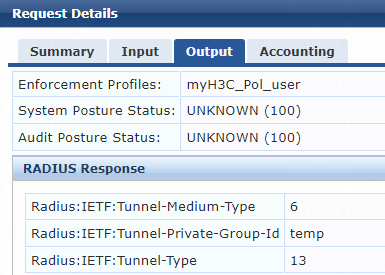
· Specify the VLAN group name to be assigned. Select Radius:IETF from the type list, select Tunnel-Private-Group-Id from the name list, and set the attribute value. For example, set the attribute value to temp.
· Specify the type of the value in the Tunnel-Private-Group-Id attribute field. For VLAN assignment, select Radius:IETF from the type list, select Tunnel-Type from the name list, and set the attribute value to VLAN (13).
Figure 80 Specifying attribute parameters in the enforcement profile

Verifying the configuration
1. On the ClearPass server, view user access request details:
# From the left navigation pane, select Monitoring > Live Monitoring > Access Tracker.
# On the page that opens, view the access request record and verify that the client has passed 802.1X or MAC authentication and come online. To view details of the access request record, click the access request record.
Figure 81 Viewing access request details
2. On the switch, verify that the online 802.1X or MAC authentication user is correctly assigned a VLAN ID selected from the authorization VLAN group.
# Use the display dot1x connection command to display information about online 802.1X authentication users.
[Device]display dot1x connection
Total connections: 1
Slot ID: 1
User MAC address: 0cda-411d-62f6
Access interface: Ten-GigabitEthernet1/0/49
Username: user
User access state: Successful
Authentication domain: bbb
Authentication method: EAP
Initial VLAN: 144
Authorization untagged VLAN: 100
Authorization tagged VLAN list: N/A
Authorization ACL number/name: N/A
Authorization dynamic ACL name: N/A
Authorization user profile: N/A
Authorization CAR: N/A
Authorization URL: N/A
Termination action: Default
Session timeout period: N/A
Online from: 2022/05/11 18:59:08
Online duration: 0h 0m 8s
# Use the display mac-authentication connection command to display information about online MAC authentication users.
[Device]display mac-authentication connection
Total connections: 1
Slot ID: 1
User MAC address: 0cda-411d-62f6
Access interface: Ten-GigabitEthernet1/0/49
Username: user
User access state: Successful
Authentication domain: mac-auth
IPv4 address: 101.0.145.39
Initial VLAN: 144
Authorization untagged VLAN: 100
Authorization tagged VLAN: N/A
Authorization ACL number/name: N/A
Authorization dynamic ACL name: N/A
Authorization user profile: N/A
Authorization CAR: N/A
Authorization URL: N/A
Termination action: Default
Session timeout period: N/A
Online from: 2022/05/13 10:09:19
Online duration: 0h 0m 1s
The output shows that VLAN 100 from VLAN group temp has been successfully assigned to the user.
Example: Integrating the switch with ClearPass for 802.1X or MAC authentication with multiple VLANs assignment
When you use a remote server to assign multiple named authorization VLANs to users, you must create the authorization VLANs and assign names to them on the switch. This configuration is required for the switch to map the named authorization VLANs received from the server to their VLAN IDs.
When the switch select a VLAN for a user from the set of server-assigned authorization VLANs, the switch preferentially select the lowest available VLAN ID from among them.
Configuring the switch
1. Configure basic authentication settings:
¡ For MAC authentication users, configure the switch as described in "Example: Integrating the switch with ClearPass for MAC authentication with a shared user account."
¡ For 802.1X authentication users, configure the switch as described in "Example: Integrating the switch with ClearPass for 802.1X CHAP authentication."
2. Create named authorization VLANs and assign names to them. In this example, create VLANs 100 and 200, and assign name v1 to VLAN 100 and name v2 to VLAN 200.
[Device] vlan 100
[Device-vlan100] name v1
[Device-vlan100] quit
[Device] vlan 200
[Device-vlan200] name v2
[Device-vlan200] quit
Configuring the ClearPass server
Configure basic settings:
· Configure the ClearPass server for MAC authentication users as described in "Example: Integrating the switch with ClearPass for MAC authentication with a shared user account."
· Configure the ClearPass server for 802.1X users as described in "Example: Integrating the switch with ClearPass for 802.1X CHAP authentication."
For multiple VLANs assignment, you must modify the attribute settings on the Attributes tab for the enforcement profile, as follows:
· Specify the tunnel medium type. Select Radius:IETF from the type list, select Tunnel-Medium-Type from the name list, and set the attribute value to IEEE-802 (6).
A value of 6 indicates that the tunnel medium type is 802, which supports VLAN assignment.
· Specify the VLAN IDs and VLAN names to be assigned. Select Radius:IETF from the type list, select Tunnel-Private-Group-Id from the name list, and set the attribute value. For example, set the attribute value to 400 500 v1 v2.
· Specify the type of the value in the Tunnel-Private-Group-Id attribute field. For VLAN assignment, select Radius:IETF from the type list, select Tunnel-Type from the name list, and set the attribute value to VLAN (13).
Figure 82 Specifying attribute parameters in the enforcement profile
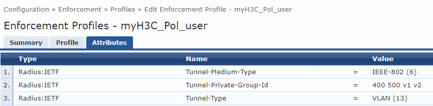
Verifying the configuration
1. On the ClearPass server, view user access request details:
# From the left navigation pane, select Monitoring > Live Monitoring > Access Tracker.
# On the page that opens, view the access request record and verify that the client has passed 802.1X or MAC authentication and come online. To view details of the access request record, click the access request record.
Figure 83 Viewing access request details
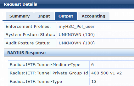
2. On the switch, verify that the online 802.1X or MAC authentication user is correctly assigned a VLAN selected from the assigned set of authorization VLAN IDs and names.
# Use the display dot1x connection command to display information about online 802.1X authentication users.
[Device]display dot1x connection
Total connections: 1
Slot ID: 1
User MAC address: 0cda-411d-62f6
Access interface: Ten-GigabitEthernet1/0/49
Username: user
User access state: Successful
Authentication domain: bbb
Authentication method: EAP
Initial VLAN: 144
Authorization untagged VLAN: 100
Authorization tagged VLAN list: N/A
Authorization ACL number/name: N/A
Authorization dynamic ACL name: N/A
Authorization user profile: N/A
Authorization CAR: N/A
Authorization URL: N/A
Termination action: Default
Session timeout period: N/A
Online from: 2022/05/11 19:07:58
Online duration: 0h 0m 14s
# Use the display mac-authentication connection command to display information about online MAC authentication users. (Details not shown.)
The output shows that VLAN 100 has been selected from the set of server-assigned authorization VLANs and assigned to the user.
Examples: Integrating the switch with ClearPass for 802.1X authentication with assignment of VLAN IDs with the tagged or untagged attribute
Restrictions and guidelines
To assign VLAN IDs with the tagged or untagged attribute suffix, make sure the user access port is a hybrid or trunk port that performs port-based access control. For users attached to an access port, assignment of VLANs with the tagged or untagged attribute suffix cannot take effect and they will be unable to come online.
Example: Integrating the switch with ClearPass for 802.1X authentication with automatic assignment of only tagged VLANs
When you configure the remote server to assign only tagged VLANs to users, the PVID (default VLAN ID) of the port does not change.
Configuring the switch
Configure the switch as described in "Example: Integrating the switch with ClearPass for 802.1X CHAP authentication."
Configuring the ClearPass server
Configure the ClearPass server as described in "Example: Integrating the switch with ClearPass for 802.1X CHAP authentication."
To assign tagged VLANs to users, you must modify the attribute settings on the Attributes tab for the enforcement profile, as follows:
· Specify the tunnel medium type. Select Radius:IETF from the type list, select Tunnel-Medium-Type from the name list, and set the attribute value to IEEE-802 (6).
· Specify the tagged VLAN IDs to be assigned in VLANIDt format, with t represents tagged. Select Radius:IETF from the type list, select Tunnel-Private-Group-Id from the name list, and set the attribute value. For example, to assign VLANs 7 and 9, set the attribute value to 7t 9t.
· Specify the type of the value in the Tunnel-Private-Group-Id attribute field. For VLAN assignment, select Radius:IETF from the type list, select Tunnel-Type from the name list, and set the attribute value to VLAN (13).
Figure 84 Specifying attribute parameters in the enforcement profile
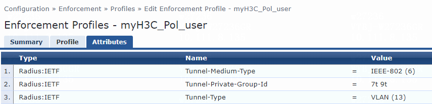
Verifying the configuration
1. On the ClearPass server, view user access request details:
# From the left navigation pane, select Monitoring > Live Monitoring > Access Tracker.
# On the page that opens, view the access request record and verify that the client has passed 802.1X authentication and come online. To view details of the access request record, click the access request record.
Figure 85 Viewing access request details

2. On the switch, verify that the online 802.1X authentication user is correctly assigned the specified VLAN information.
# Use the display dot1x connection command to display information about online 802.1X authentication users.
[Device] display dot1x connection
Total connections: 1
Slot ID: 1
User MAC address: 0cda-411d-62f6
Access interface: Ten-GigabitEthernet1/0/49
Username: user
User access state: Successful
Authentication domain: bbb
Authentication method: EAP
Initial VLAN: 144
Authorization untagged VLAN: 144
Authorization tagged VLAN list: 7 9
Authorization ACL number/name: N/A
Authorization dynamic ACL name: N/A
Authorization user profile: N/A
Authorization CAR: N/A
Authorization URL: N/A
Termination action: Default
Session timeout period: N/A
Online from: 2022/05/12 09:57:20
Online duration: 0h 18m 37s
The output shows that tagged VLANs 7 and 9 have been successfully assigned to the user. Because no untagged VLANs have been specified on the server, the PVID of the user-attached port remains unchanged.
Example: Integrating the switch with ClearPass for 802.1X authentication with assignment of VLANs that contain one untagged VLAN
When you configure the remote server to assign a VLAN string containing one untagged VLAN, the untagged VLAN becomes the PVID of the port.
Configuring the switch
Configure the switch as described in "Example: Integrating the switch with ClearPass for 802.1X CHAP authentication."
Configuring the ClearPass server
Configure the ClearPass server as described in "Example: Integrating the switch with ClearPass for 802.1X CHAP authentication."
For assignment of a VLAN string containing one untagged VLAN, you must modify the attribute settings on the Attributes tab for the enforcement profile, as follows:
· Specify the tunnel medium type. Select Radius:IETF from the type list, select Tunnel-Medium-Type from the name list, and set the attribute value to IEEE-802 (6).
· Specify multiple tagged VLAN IDs and one untagged VLAN. Select Radius:IETF from the type list, select Tunnel-Private-Group-Id from the name list, and set the attribute value. When you set the attribute value, specify tagged VLANs in VLANIDt format, where t represents tagged. Specify the untagged VLAN in VLANIDu format, where u represents untagged. In this example, set the attribute value to 7t 9t 10u.
· Specify the type of the value in the Tunnel-Private-Group-Id attribute field. For VLAN assignment, select Radius:IETF from the type list, select Tunnel-Type from the name list, and set the attribute value to VLAN (13).
Figure 86 Specifying attribute parameters in the enforcement profile
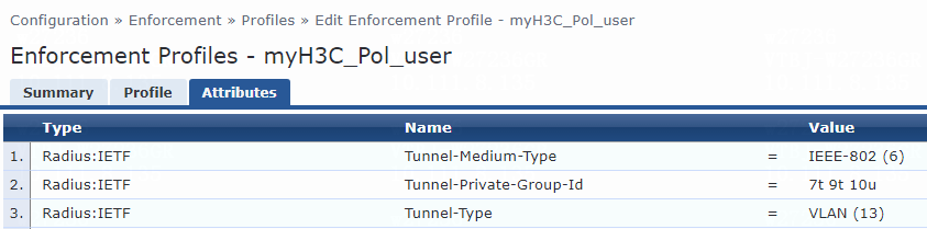
Verifying the configuration
1. On the ClearPass server, view user access request details:
# From the left navigation pane, select Monitoring > Live Monitoring > Access Tracker.
# On the page that opens, view the access request record and verify that the client has passed 802.1X authentication and come online. To view details of the access request record, click the access request record.
Figure 87 Viewing access request details
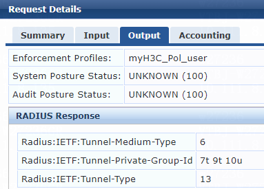
2. On the switch, verify that the online 802.1X authentication user is correctly assigned the specified VLAN information.
# Use the display dot1x connection command to display information about online 802.1X authentication users.
[Device]display dot1x connection
Total connections: 1
Slot ID: 1
User MAC address: 0cda-411d-62f6
Access interface: Ten-GigabitEthernet1/0/49
Username: user
User access state: Successful
Authentication domain: bbb
Authentication method: EAP
Initial VLAN: 144
Authorization untagged VLAN: 10
Authorization tagged VLAN list: 7 9
Authorization ACL number/name: N/A
Authorization dynamic ACL name: N/A
Authorization user profile: N/A
Authorization CAR: N/A
Authorization URL: N/A
Termination action: Default
Session timeout period: N/A
Online from: 2022/05/12 10:21:00
Online duration: 0h 0m 3s
The output shows that tagged VLAN 7, tagged VLAN 9, and untagged VLAN 10 have been successfully assigned to the user. The PVID of the port has changed to VLAN 10.
Example: Integrating the switch with ClearPass for 802.1X authentication with assignment of VLANs that contain multiple untagged VLANs
When you configure the remote server to assign a set of VLANs that contain multiple untagged VLANs, the device selects the leftmost VLAN ID without a suffix or the leftmost VLAN ID with a suffix of u as the authorization untagged VLAN, whichever is more leftmost. The remaining VLAN IDs with a suffix of u or without a suffix will be assigned as tagged VLANs. On the switch, the PVID of the user-attached port will change to the untagged authorization VLAN.
Configuring the switch
Configure the switch as described in "Example: Integrating the switch with ClearPass for 802.1X CHAP authentication."
Configuring the ClearPass server
Configure the ClearPass server as described in "Example: Integrating the switch with ClearPass for 802.1X CHAP authentication."
To assign multiple tagged and untagged VLANs to a user, modify the attribute settings on the Attributes tab for the enforcement profile, as follows:
· Specify the tunnel medium type. Select Radius:IETF from the type list, select Tunnel-Medium-Type from the name list, and set the attribute value to IEEE-802 (6).
A value of 6 indicates that the tunnel medium type is 802, which supports VLAN assignment.
· Specify multiple tagged and untagged VLAN IDs. Select Radius:IETF from the type list, select Tunnel-Private-Group-Id from the name list, and set the attribute value. When you set the attribute value, specify tagged VLANs in VLANIDt format, where t represents tagged. Specify untagged VLANs in VLANIDu format, where u represents untagged. In this example, set the attribute value to 8u 7t 9t 10u.
· Specify the type of the value in the Tunnel-Private-Group-Id attribute field. For VLAN assignment, select Radius:IETF from the type list, select Tunnel-Type from the name list, and set the attribute value to VLAN (13).
Figure 88 Specifying attribute parameters in the enforcement profile
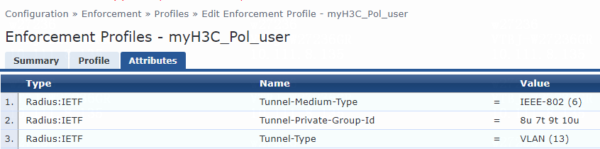
Verifying the configuration
1. On the ClearPass server, view user access request details:
# From the left navigation pane, select Monitoring > Live Monitoring > Access Tracker.
# On the page that opens, view the access request record and verify that the client has passed 802.1X authentication and come online. To view details of the access request record, click the access request record.
Figure 89 Viewing access request details
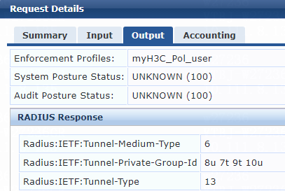
2. On the switch, verify that the online 802.1X authentication user is correctly assigned the specified VLAN information.
# Use the display dot1x connection command to display information about online 802.1X authentication users.
[Device] display dot1x connection
Total connections: 1
Slot ID: 1
User MAC address: 0cda-411d-62f6
Access interface: Ten-GigabitEthernet1/0/49
Username: user
User access state: Successful
Authentication domain: bbb
Authentication method: EAP
Initial VLAN: 144
Authorization untagged VLAN: 8
Authorization tagged VLAN list: 7 9-10
Authorization ACL number/name: N/A
Authorization dynamic ACL name: N/A
Authorization user profile: N/A
Authorization CAR: N/A
Authorization URL: N/A
Termination action: Default
Session timeout period: N/A
Online from: 2022/05/12 10:26:36
Online duration: 0h 0m 4s
The output shows that tagged VLAN 7, VLAN 9, and VLAN 10, and untagged VLAN 8 have been assigned to the user. In addition, verify that the PVID of the port has changed to VLAN 8.
Example: Integrating the switch with ClearPass for 802.1X, MAC, or portal authentication with ACL assignment
Network configuration
As shown in Figure 90, configure the switch to work in conjunction with a ClearPass server to do 802.1X, MAC, or portal authentication for the client connected to Ten-GigabitEthernet 1/0/49. The client must pass 802.1X, MAC, or portal authentication to access network resources.
Configure the switch as follows:
· Use the ClearPass server as the RADIUS server to perform 802.1X, MAC, or portal authentication for the client.
· Configure the ClearPass server to assign an authorization ACL to the client access port after the client passes 802.1X, MAC, or portal authentication.

Software versions used
This configuration example was created and verified on the following hardware and software versions:
|
Hardware |
Software version |
|
H3C S5130-HI switch |
R3507P02 |
|
Aruba ClearPass server |
Aruba ClearPass Policy Manager (CPPM) v6.9.7 |
Procedures
When you configure the remote server to assign an ACL to users, make sure the ACL has been created on the device.
Configuring the switch
1. Configure basic authentication settings:
¡ For MAC authentication users, configure the switch as described in "Example: Integrating the switch with ClearPass for MAC authentication with a shared user account."
¡ For 802.1X authentication users, configure the switch as described in "Example: Integrating the switch with ClearPass for 802.1X CHAP authentication."
2. Configure advanced ACL rule 3999 to permit all packets sourced from any source IP address.
[Device] acl advanced 3999
[Device-acl-ipv4-adv-3999] rule 0 permit ip source any
Configuring the ClearPass server
Configure basic settings:
· Configure the ClearPass server for MAC authentication users as described in "Example: Integrating the switch with ClearPass for MAC authentication with a shared user account."
· Configure the ClearPass server for 802.1X users as described in "Example: Integrating the switch with ClearPass for 802.1X CHAP authentication."
For ACL assignment, you must modify the attribute settings on the Attributes tab for the enforcement profile. In this example, set the type to Radius:IETF, name to Filter-Id, and value to 3999.
|
|
NOTE: If the value for the Filter-Id attribute is a number, the switch treats that number as an ACL number. If the value is not a number, the switch treats that value as a user profile. |
Figure 91 Specifying attribute parameters in the enforcement profile
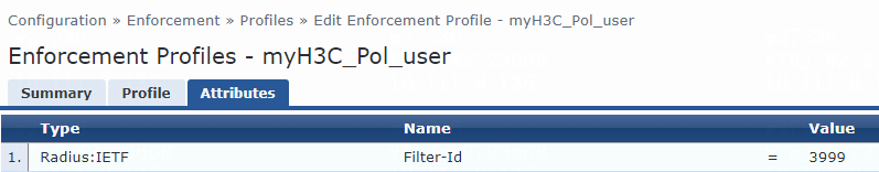
Verifying the configuration
1. On the ClearPass server, view user access request details:
# From the left navigation pane, select Monitoring > Live Monitoring > Access Tracker.
# On the page that opens, view the access request record and verify that the client has passed 802.1X, MAC, or portal authentication and come online. To view details of the access request record, click the access request record.
Figure 92 Viewing access request details
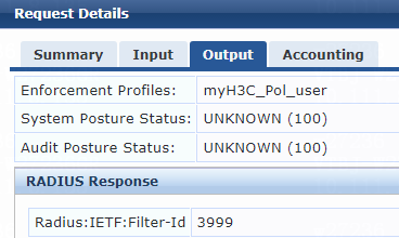
2. On the switch, verify that the user is correctly assigned the specified ACL.
# Use the display dot1x connection command to display information about online 802.1X authentication users.
[Device]display dot1x connection
Total connections: 1
Slot ID: 1
User MAC address: 0cda-411d-62f6
Access interface: Ten-GigabitEthernet1/0/49
Username: user
User access state: Successful
Authentication domain: bbb
Authentication method: EAP
Initial VLAN: 144
Authorization untagged VLAN: N/A
Authorization tagged VLAN list: N/A
Authorization ACL number/name: 3999
Authorization dynamic ACL name: N/A
Authorization user profile: N/A
Authorization CAR: N/A
Authorization URL: N/A
Termination action: Default
Session timeout period: N/A
Online from: 2022/05/12 10:34:53
Online duration: 0h 0m 13s
The output shows that ACL 3999 has been successfully assigned to the user.
# Use the display mac-authentication connection command to display information about online MAC authentication users. (Details not shown.)
# Use the display portal user command to display information about portal users. (Details not shown.)
Example: Integrating the switch with ClearPass for authentication with user profile assignment
Network configuration
As shown in Figure 93, configure the switch to work in conjunction with a ClearPass server to do 802.1X, MAC, or portal authentication for the client connected to Ten-GigabitEthernet 1/0/49. The client must pass 802.1X, MAC, or portal authentication to access network resources. In this example, 802.1X authentication is used.
Configure the switch as follows:
· Use the ClearPass server as the RADIUS server to perform 802.1X authentication for the client.
· Configure the ClearPass server to assign an authorization user profile to the client after the client passes 802.1X authentication.

Software versions used
This configuration example was created and verified on the following hardware and software versions:
|
Hardware |
Software version |
|
H3C S5130-HI switch |
R3507P02 |
|
Aruba ClearPass server |
Aruba ClearPass Policy Manager (CPPM) v6.9.7 |
Procedures
When you use the remote server to assign a user profile to users, make sure the user profile has been created on the device.
Configuring the switch
1. Configure the switch as described in "Example: Integrating the switch with ClearPass for 802.1X CHAP authentication."
2. Configure a QoS policy for limiting the traffic rate for the user:
# Create a traffic class named class to match all packets.
[Device] traffic classifier class
[Device-classifier-class] if-match any
[Device-classifier-class] quit
# Create a traffic behavior named for_ub, and configure a traffic policing action (CIR 10000 kbps).
[Device] traffic behavior for_ub
[Device-behavior-for_ub] car cir 10000
[Device-behavior-for_ub] quit
# Create a QoS policy named for_ub, and associate traffic class class and traffic behavior for_ub in the QoS policy.
[Device] qos policy for_ub
[Device-qospolicy-for_ub] classifier class behavior for_ub
[Device-qospolicy-for_ub] quit
3. Create a user profile for the user and apply the QoS policy to the user profile:
# Create a user profile named ub.
[Device] user-profile ub
# Apply QoS policy for_ub to the inbound direction of user profile ub.
[Device-user-profile-ub] qos apply policy for_ub inbound
[Device-user-profile-ub] quit
Configuring the ClearPass server
Configure the ClearPass server as described in "Example: Integrating the switch with ClearPass for 802.1X CHAP authentication."
For user profile assignment, you must modify the attribute settings on the Attributes tab for the enforcement profile. Set the type to Radius:IETF, name to Filter-Id, and value to ub.
|
|
NOTE: If the value for the Filter-Id attribute is a number, the switch treats that number as an ACL number. If the value is not a number, the switch treats that value as a user profile. |
Figure 94 Specifying attribute parameters in the enforcement profile
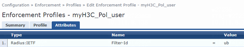
Verifying the configuration
1. On the ClearPass server, view user access request details:
# From the left navigation pane, select Monitoring > Live Monitoring > Access Tracker.
# On the page that opens, view the access request record and verify that the client has passed 802.1X authentication and come online. To view details of the access request record, click the access request record.
Figure 95 Viewing access request details
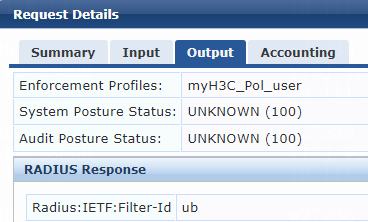
2. On the switch, verify that the user is correctly assigned the specified user profile.
# Use the display dot1x connection command to display information about online 802.1X authentication users.
[Device] display dot1x connection
Total connections: 1
Slot ID: 1
User MAC address: 0cda-411d-62f6
Access interface: Ten-GigabitEthernet1/0/49
Username: user
User access state: Successful
Authentication domain: bbb
Authentication method: EAP
Initial VLAN: 144
Authorization untagged VLAN: N/A
Authorization tagged VLAN list: N/A
Authorization ACL number/name: N/A
Authorization dynamic ACL name: N/A
Authorization user profile: ub
Authorization CAR: N/A
Authorization URL: N/A
Termination action: Default
Session timeout period: N/A
Online from: 2022/05/12 10:52:34
Online duration: 0h 0m 4s
The output shows that user profile ub has been successfully assigned to the user.
Example: Integrating the switch with ClearPass for authentication with CAR assignment
Network configuration
As shown in Figure 96, configure the switch to work in conjunction with a ClearPass server to do 802.1X or MAC authentication for the client connected to Ten-GigabitEthernet 1/0/49. The client must pass 802.1X or MAC authentication to access network resources. In this example, 802.1X authentication is used.
Configure the switch as follows:
· Use the ClearPass server as the RADIUS server to perform 802.1X authentication for the client.
· Configure the ClearPass server to assign an authorization CAR policy (specifying the average input rate, peak input rate, average output rate, and peak output rate) to the client after the client passes 802.1X authentication.

Software versions used
This configuration example was created and verified on the following hardware and software versions:
|
Hardware |
Software version |
|
H3C S5130-HI switch |
R3507P02 |
|
Aruba ClearPass server |
Aruba ClearPass Policy Manager (CPPM) v6.9.7 |
Procedures
Configuring the switch
Configure the switch as described in "Example: Integrating the switch with ClearPass for 802.1X CHAP authentication."
Configuring the ClearPass server
Configure the ClearPass server as described in "Example: Integrating the switch with ClearPass for 802.1X CHAP authentication."
For CAR policy assignment, modify the attribute settings on the Attributes tab for the enforcement profile, as follows:
· Select Radius:H3C from the type list, select H3C-Input-Average-Rate from the name list, and set the attribute value to 80000.
· Select Radius:H3C from the type list, select H3C-Input-Peak-Rate from the name list, and set the attribute value to 90000.
· Select Radius:H3C from the type list, select H3C-Output-Average-Rate from the name list, and set the attribute value to 88000.
· Select Radius:H3C from the type list, select H3C-Output-Peak-Rate from the name list, and set the attribute value to 98000.
Figure 97 Specifying attribute parameters in the enforcement profile
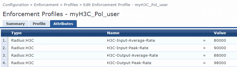
If the H3C-Output-Average-Rate and H3C-Output-Peak-Rate attributes do not exist on the ClearPass server, perform the following tasks to add them to the RADIUS dictionary for H3C on the server:
1. From the left navigation pane, select Administration > Dictionaries > RADIUS.
Figure 98 Entering RADIUS dictionaries page
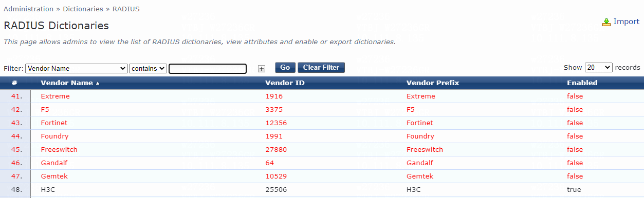
2. Click H3C in the Vendor Name column to view all H3C proprietary RADIUS attributes.
Figure 99 Viewing RADIUS H3C dictionary attributes
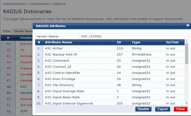
3. Click Export to export the H3C proprietary RADIUS attribute dictionary.
4. Open the .xml file.
5. Add the H3C-Output-Average-Rate and H3C-Output-Peak-Rate attributes in the same format as the H3C-Input-Average-Rate and H3C-Input-Peak-Rate attributes, respectively.
Figure 100 Editing the .xml file
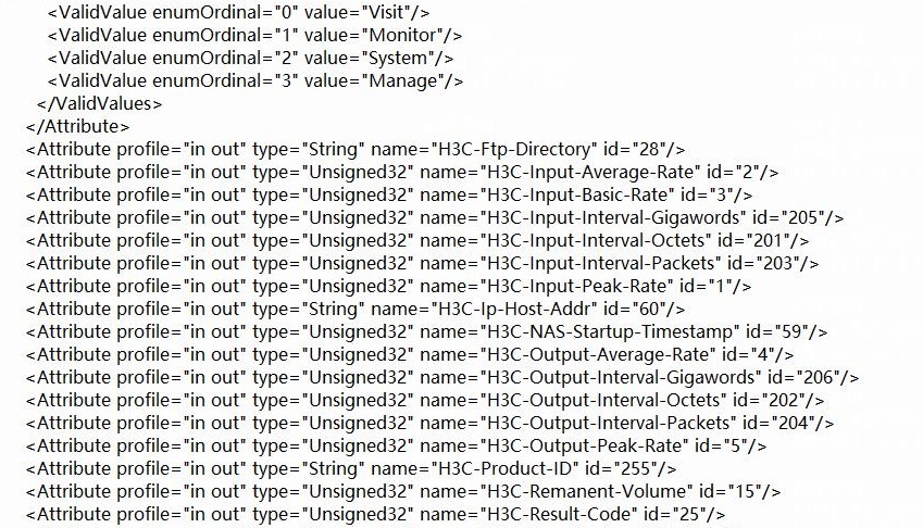
6. Save the .xml file.
7. Import the file to the server:
a. On the Administration > Dictionaries > RADIUS page, click Import in the upper right corner.
b. On the Import from file page that opens, click Choose File in the Select File field to select the dictionary file to be imported, and then click Import.
8. Click H3C in the Vendor Name column to view all H3C proprietary RADIUS attributes. Verify that the H3C-Output-Average-Rate and H3C-Output-Peak-Rate attributes have been added to the dictionary on the server.
Figure 101 Viewing H3C proprietary RADIUS attributes
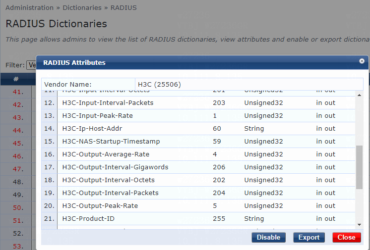
Verifying the configuration
1. On the ClearPass server, view user access request details:
# From the left navigation pane, select Monitoring > Live Monitoring > Access Tracker.
# On the page that opens, view the access request record and verify that the client has passed 802.1X authentication and come online. To view details of the access request record, click the access request record.
Figure 102 Viewing access request details
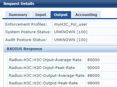
2. On the switch, verify that the user is correctly assigned the specified CAR policy.
# Use the display dot1x connection command to display information about online 802.1X authentication users.
[Device] display dot1x connection
Total connections: 1
Slot ID: 1
User MAC address: 0cda-411d-62f6
Access interface: Ten-GigabitEthernet1/0/49
Username: user
User access state: Successful
Authentication domain: bbb
Authentication method: EAP
Initial VLAN: 144
Authorization untagged VLAN: N/A
Authorization tagged VLAN list: N/A
Authorization ACL number/name: N/A
Authorization dynamic ACL name: N/A
Authorization user profile: N/A
Authorization CAR:
Average input rate: 80000 bps
Peak input rate: 90000 bps
Average output rate: 88000 bps
Peak output rate: 98000 bps
Authorization URL: N/A
Termination action: Default
Session timeout period: N/A
Online from: 2022/05/12 10:43:24
Online duration: 0h 0m 4s
The output shows that the CAR policy has been successfully assigned to the user.
Examples: Integrating the switch with ClearPass for periodic 802.1X or MAC reauthentication
Network configuration
As shown in Figure 103, configure the switch to work in conjunction with a ClearPass server to do 802.1X or MAC authentication for the client connected to Ten-GigabitEthernet 1/0/49. The client must pass 802.1X or MAC authentication to access network resources.
Configure the switch as follows:
· Use the ClearPass server as the RADIUS server to perform 802.1X or MAC authentication for the client.
· Configure the ClearPass server to assign the Session-Timeout and Termination-Action attributes to the client after the client passes 802.1X or MAC authentication.

Software versions used
This configuration example was created and verified on the following hardware and software versions:
|
Hardware |
Software version |
|
H3C S5130-HI switch |
R3507P02 |
|
Aruba ClearPass server |
Aruba ClearPass Policy Manager (CPPM) v6.9.7 |
Example: Enabling periodic reauthentication upon session timeout
If the server assigns a session timeout timer value and sets the Termination-Action attribute to RADIUS-Request (1), the device reauthenticates the user upon session timeout. The device perform this operation, even if periodic online user reauthentication is disabled on the user access port.
Configuring the switch
For MAC authentication users, configure the switch as described in "Example: Integrating the switch with ClearPass for MAC authentication with a shared user account."
For 802.1X authentication users, configure the switch as described in "Example: Integrating the switch with ClearPass for 802.1X CHAP authentication."
Configuring the ClearPass server
Configure basic settings:
· Configure the ClearPass server for MAC authentication users as described in "Example: Integrating the switch with ClearPass for MAC authentication with a shared user account."
· Configure the ClearPass server for 802.1X users as described in "Example: Integrating the switch with ClearPass for 802.1X CHAP authentication."
In this example, you must modify the attribute settings on the Attributes tab for the enforcement profile, as follows:
· Select Radius:IETF from the type list, select Session-Timeout from the name list, and set the attribute value to 15.
· Select Radius:IETF from the type list, select Termination-Action from the name list, and set the attribute value to RADIUS-Request (1).
Figure 104 Specifying attribute parameters in the enforcement profile
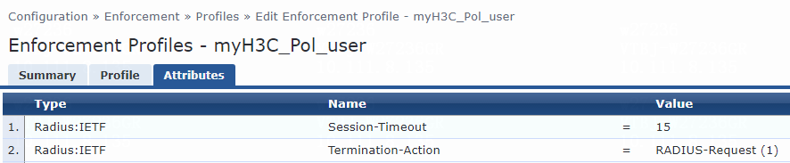
Verifying the configuration
1. On the ClearPass server, view user access request details:
# From the left navigation pane, select Monitoring > Live Monitoring > Access Tracker.
# On the page that opens, view the access request record and verify that the client has passed 802.1X or MAC authentication and come online. To view details of the access request record, click the access request record.
Figure 105 Viewing access request details
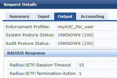
2. On the switch, verify that the online 802.1X or MAC authentication user is correctly assigned the termination action and session timeout period information.
# Use the display dot1x connection command to display information about online 802.1X authentication users.
[Device] display dot1x connection
Total connections: 1
Slot ID: 1
User MAC address: 0cda-411d-62f6
Access interface: Ten-GigabitEthernet1/0/49
Username: user
User access state: Successful
Authentication domain: bbb
Authentication method: EAP
Initial VLAN: 144
Authorization untagged VLAN: N/A
Authorization tagged VLAN list: N/A
Authorization ACL number/name: N/A
Authorization dynamic ACL name: N/A
Authorization user profile: N/A
Authorization CAR: N/A
Authorization URL: N/A
Termination action: Radius-request
Session timeout period: 15 s
Online from: 2022/05/12 11:02:14
Online duration: 0h 0m 4s
The output shows that the Session-Timeout and Termination-Action attributes have been successfully assigned to the user. The session timeout time is 15 seconds, and the termination action is Radius-request (reauthentication).
# Use the display mac-authentication connection command to display information about online MAC authentication users.
[Device] display mac-authentication connection
Total connections: 1
Slot ID: 1
User MAC address: 0cda-411d-62f6
Access interface: Ten-GigabitEthernet1/0/49
Username: user
User access state: Successful
Authentication domain: mac-auth
IPv4 address: 101.0.145.39
Initial VLAN: 144
Authorization untagged VLAN: N/A
Authorization tagged VLAN: N/A
Authorization ACL number/name: N/A
Authorization dynamic ACL name: N/A
Authorization user profile: N/A
Authorization CAR: N/A
Authorization URL: N/A
Termination action: Radius-request
Session timeout period: 15 sec
Online from: 2022/05/13 11:20:20
Online duration: 0h 0m 4s
The output shows that the Session-Timeout and Termination-Action attributes have been successfully assigned to the user. The session timeout time is 15 seconds, and the termination action is Radius-request (reauthentication).
3. Capture packets to verify that the switch reauthenticates the online 802.1X or MAC authentication user upon expiration of the session timeout timer.
Figure 106 Periodic 802.1X reauthentication

Figure 107 Periodic MAC reauthentication
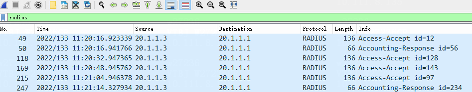
The output shows that the switch reauthenticated the online 802.1X or MAC authentication user upon expiration of the session timeout timer and the user passed authentication.
Example: Logging off users upon session timeout
To log off a user upon session timeout, this example uses the following settings:
· Disable periodic online user reauthentication on the user access port.
· Configure the server to assign a session timeout timer value and set the termination action upon session timeout to Default (0), which represents the logoff action.
Configuring the switch
For MAC authentication users, configure the switch as described in "Example: Integrating the switch with ClearPass for MAC authentication with a shared user account."
For 802.1X authentication users, configure the switch as described in "Example: Integrating the switch with ClearPass for 802.1X CHAP authentication."
Configuring the ClearPass server
Configure basic settings:
· Configure the ClearPass server for MAC authentication users as described in "Example: Integrating the switch with ClearPass for MAC authentication with a shared user account."
· Configure the ClearPass server for 802.1X users as described in "Example: Integrating the switch with ClearPass for 802.1X CHAP authentication."
In this example, you must modify the attribute settings on the Attributes tab for the enforcement profile, as follows:
· Select Radius:IETF from the type list, select Session-Timeout from the name list, and set the attribute value to 15.
· Select Radius:IETF from the type list, select Termination-Action from the name list, and set the attribute value to Default (0).
Figure 108 Specifying attribute parameters in the enforcement profile

Verifying the configuration
1. On the ClearPass server, view user access request details before and after session timeout timer expires:
# From the left navigation pane, select Monitoring > Live Monitoring > Access Tracker.
# On the page that opens, view the access request record. To view details of the access request record, click the access request record.
Figure 109 Viewing user online information

Figure 110 Viewing user offline information
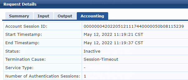
2. On the switch, verify that the user can be correctly assigned the termination action and session timeout timer value.
# Use the display dot1x connection command to display information about online 802.1X authentication users.
[Device]display dot1x connection
Total connections: 1
Slot ID: 1
User MAC address: 0cda-411d-62f6
Access interface: Ten-GigabitEthernet1/0/49
Username: user
User access state: Successful
Authentication domain: bbb
Authentication method: EAP
Initial VLAN: 144
Authorization untagged VLAN: N/A
Authorization tagged VLAN list: N/A
Authorization ACL number/name: N/A
Authorization dynamic ACL name: N/A
Authorization user profile: N/A
Authorization CAR: N/A
Authorization URL: N/A
Termination action: Default
Session timeout period: 15 s
Online from: 2022/05/12 11:19:21
Online duration: 0h 0m 4s
The output shows that the Session-Timeout and Termination-Action attributes have been successfully assigned to the user.
# Use the display mac-authentication connection command to display information about online MAC authentication users.
[Device] display mac-authentication connection
Total connections: 1
Slot ID: 1
User MAC address: 0cda-411d-62f6
Access interface: Ten-GigabitEthernet1/0/49
Username: user
User access state: Successful
Authentication domain: mac-auth
IPv4 address: 101.0.145.39
Initial VLAN: 144
Authorization untagged VLAN: N/A
Authorization tagged VLAN: N/A
Authorization ACL number/name: N/A
Authorization dynamic ACL name: N/A
Authorization user profile: N/A
Authorization CAR: N/A
Authorization URL: N/A
Termination action: Default
Session timeout period: 15 sec
Online from: 2022/05/13 14:33:12
Online duration: 0h 0m 5s
The output shows that the Session-Timeout and Termination-Action attributes have been successfully assigned to the user.
3. Capture packets to verify that the switch logs off the online 802.1X or MAC user upon session timeout.
In this example, the logoff record of the online 802.1X user is displayed.
Figure 111 Logging off the online 802.1X user
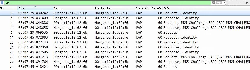
The output shows that the switch logged off the online 802.1X user upon session timeout.
Example: Performing periodic reauthentication prior to session timeout to keep users online
To prevent an online 802.1X or MAC authentication user from being logged off because of session timeout, this example uses the following settings to make sure the user is reauthenticated before a session timeout:
· Configure the user access port with the following settings on the switch:
¡ Enable periodic online user reauthentication.
¡ Set the periodic reauthentication timer to a lower value than the server-assigned session timeout timer value.
· Configure authorization settings for the user on the server as follows:
¡ Set a session timeout timer value.
¡ Set the termination action to Default (0), which represents the logoff action.
Configuring the switch
For 802.1X authentication users, configure the switch as follows:
1. Configure the switch as described in "Example: Integrating the switch with ClearPass for 802.1X CHAP authentication."
2. Enable periodic online user reauthentication on Ten-GigabitEthernet 1/0/49 and set the periodic reauthentication timer to 60.
[Device]interface Ten-GigabitEthernet 1/0/49
[Device-Ten-GigabitEthernet1/0/49] dot1x re-authenticate
[Device-Ten-GigabitEthernet1/0/49] dot1x timer reauth-period 60
For MAC authentication users, configure the switch as follows:
1. Configure the switch as described in "Example: Integrating the switch with ClearPass for MAC authentication with a shared user account."
2. Set the periodic reauthentication timer to 60.
[Device] mac-authentication timer reauth-period 60
3. Set the periodic reauthentication timer to 60 and enable periodic online user reauthentication on Ten-GigabitEthernet 1/0/49.
[Device] interface Ten-GigabitEthernet 1/0/49
[Device-Ten-GigabitEthernet1/0/49] mac-authentication timer reauth-period 60
[Device-Ten-GigabitEthernet1/0/49] mac-authentication re-authenticate
[Device-Ten-GigabitEthernet1/0/49] quit
Configuring the ClearPass server
Configure basic settings:
· Configure the ClearPass server for 802.1X users as described in "Example: Integrating the switch with ClearPass for 802.1X CHAP authentication."
· Configure the ClearPass server for MAC authentication users as described in "Example: Integrating the switch with ClearPass for MAC authentication with a shared user account."
In this example, you must modify the attribute settings on the Attributes tab for the enforcement profile, as follows:
· Select Radius:IETF from the type list, select Session-Timeout from the name list, and set the attribute value to 80.
· Select Radius:IETF from the type list, select Termination-Action from the name list, and set the attribute value to Default (0).
Figure 112 Specifying attribute parameters in the enforcement profile
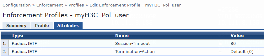
Verifying the configuration
1. On the ClearPass server, view user access request details:
# From the left navigation pane, select Monitoring > Live Monitoring > Access Tracker.
# On the page that opens, view the access request record and verify that the client has passed 802.1X or MAC authentication and come online. To view details of the access request record, click the access request record.
Figure 113 Viewing access request details

2. On the switch, verify that the online 802.1X or MAC authentication user is correctly assigned the termination action and session timeout period information.
# Use the display dot1x connection command to display information about online 802.1X authentication users.
[Device] display dot1x connection
Total connections: 1
Slot ID: 1
User MAC address: 0cda-411d-62f6
Access interface: Ten-GigabitEthernet1/0/49
Username: user
User access state: Successful
Authentication domain: bbb
Authentication method: EAP
Initial VLAN: 144
Authorization untagged VLAN: N/A
Authorization tagged VLAN list: N/A
Authorization ACL number/name: N/A
Authorization dynamic ACL name: N/A
Authorization user profile: N/A
Authorization CAR: N/A
Authorization URL: N/A
Termination action: Default
Session timeout period: 80 s
Online from: 2022/05/12 11:24:50
Online duration: 0h 0m 11s
The output shows that the Session-Timeout and Termination-Action attributes have been successfully assigned to the user.
# Use the display mac-authentication connection command to display information about online MAC authentication users.
[Device] display mac-authentication connection
Total connections: 1
Slot ID: 1
User MAC address: 0cda-411d-62f6
Access interface: Ten-GigabitEthernet1/0/49
Username: user
User access state: Successful
Authentication domain: mac-auth
IPv4 address: 101.0.145.39
Initial VLAN: 144
Authorization untagged VLAN: N/A
Authorization tagged VLAN: N/A
Authorization ACL number/name: N/A
Authorization dynamic ACL name: N/A
Authorization user profile: N/A
Authorization CAR: N/A
Authorization URL: N/A
Termination action: Default
Session timeout period: 80 sec
Online from: 2022/05/13 14:55:01
Online duration: 0h 0m 8s
The output shows that the Session-Timeout and Termination-Action attributes have been successfully assigned to the user.
3. Capture packets to verify that the switch reauthenticates the online 802.1X or MAC authentication user at periodic reauthentication intervals to keep the user online.
Figure 114 Periodic 802.1X reauthentication
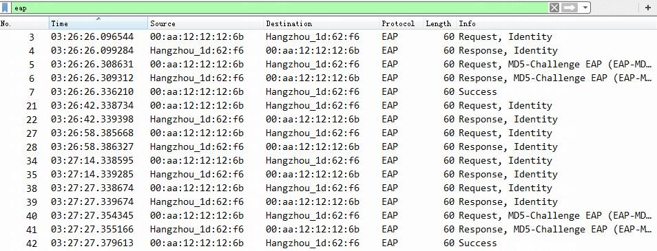
Figure 115 Periodic MAC reauthentication
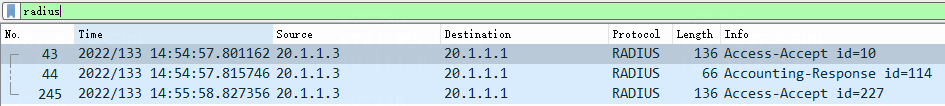
The output shows that the switch reauthenticated the online 802.1X or MAC user at the periodic reauthentication interval to keep the user online.
Example: Logging off users upon session timeout
This example shows the configuration that will cause an online user to be logged off upon session timer, even if periodic online user reauthentication is enabled on the user-attached port.
· Authorization settings for the user on the server:
¡ A session timeout timer value.
¡ Termination action upon session timeout set to Default (0), which represents the logoff action.
· On the switch, the periodic reauthentication timer on the user-attached port is longer than or equal to the server-issued session timeout timer value.
Configuring the switch
For 802.1X authentication users, configure the switch as follows:
1. Configure the switch as described in "Example: Integrating the switch with ClearPass for 802.1X CHAP authentication."
2. Enable periodic online user reauthentication on Ten-GigabitEthernet 1/0/49 and set the periodic reauthentication timer to 60 seconds.
[Device]interface Ten-GigabitEthernet 1/0/49
[Device-Ten-GigabitEthernet1/0/49] dot1x re-authenticate
[Device-Ten-GigabitEthernet1/0/49] dot1x timer reauth-period 60
For MAC authentication users, configure the switch as follows:
1. Configure the switch as described in "Example: Integrating the switch with ClearPass for MAC authentication with a shared user account."
2. Set the global periodic reauthentication timer to 60 seconds.
[Device] mac-authentication timer reauth-period 60
3. Set the periodic reauthentication timer to 60 seconds and enable periodic online user reauthentication on Ten-GigabitEthernet 1/0/49.
[Device] interface Ten-GigabitEthernet 1/0/49
[Device-Ten-GigabitEthernet1/0/49] mac-authentication timer reauth-period 60
[Device-Ten-GigabitEthernet1/0/49] mac-authentication re-authenticate
[Device-Ten-GigabitEthernet1/0/49] quit
Configuring the ClearPass server
Configure basic settings:
· Configure the ClearPass server for MAC authentication users as described in "Example: Integrating the switch with ClearPass for MAC authentication with a shared user account."
· Configure the ClearPass server for 802.1X users as described in "Example: Integrating the switch with ClearPass for 802.1X CHAP authentication."
In this example, you must modify the attribute settings on the Attributes tab for the enforcement profile, as follows:
· Select Radius:IETF from the type list, select Session-Timeout from the name list, and set the attribute value to 15.
· Select Radius:IETF from the type list, select Termination-Action from the name list, and set the attribute value to Default (0).
Figure 116 Specifying attribute parameters in the enforcement profile
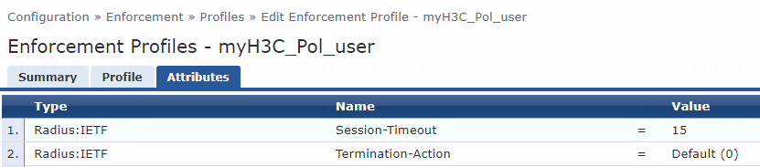
Verifying the configuration
1. On the ClearPass server, view user access request details before and after session timeout timer expires:
# From the left navigation pane, select Monitoring > Live Monitoring > Access Tracker.
# On the page that opens, view the access request record. To view details of the access request record, click the access request record.
Figure 117 Viewing online user information

Figure 118 Viewing online user information
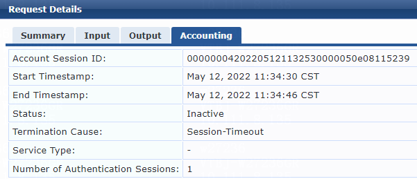
2. On the switch, verify that the online 802.1X or MAC authentication user is correctly assigned the termination action and session timeout period information.
# Use the display dot1x connection command to display information about online 802.1X authentication users.
[Device]display dot1x connection
Total connections: 1
Slot ID: 1
User MAC address: 0cda-411d-62f6
Access interface: Ten-GigabitEthernet1/0/49
Username: user
User access state: Successful
Authentication domain: bbb
Authentication method: EAP
Initial VLAN: 144
Authorization untagged VLAN: N/A
Authorization tagged VLAN list: N/A
Authorization ACL number/name: N/A
Authorization dynamic ACL name: N/A
Authorization user profile: N/A
Authorization CAR: N/A
Authorization URL: N/A
Termination action: Default
Session timeout period: 15 s
Online from: 2022/05/13 14:34:58
Online duration: 0h 0m 4s
The output shows that the Session-Timeout and Termination-Action attributes have been successfully assigned to the user.
# Use the display mac-authentication connection command to display information about online MAC authentication users.
[Device]display mac-authentication connection
Total connections: 1
Slot ID: 1
User MAC address: 0cda-411d-62f6
Access interface: Ten-GigabitEthernet1/0/49
Username: user
User access state: Successful
Authentication domain: mac-auth
IPv4 address: 101.0.145.39
Initial VLAN: 144
Authorization untagged VLAN: N/A
Authorization tagged VLAN: N/A
Authorization ACL number/name: N/A
Authorization dynamic ACL name: N/A
Authorization user profile: N/A
Authorization CAR: N/A
Authorization URL: N/A
Termination action: Default
Session timeout period: 15 sec
Online from: 2022/05/13 14:59:25
Online duration: 0h 0m 5s
The output shows that the Session-Timeout and Termination-Action attributes have been successfully assigned to the user.
3. Capture packets to verify that the switch logs off the online 802.1X or MAC authentication user upon session timeout. (Details not shown.)
Example: Solely depending on switch settings to control the action to take on online users upon session timeout
To use only the switch configuration to control the action on online 802.1X or MAC authentication users upon session timeout, do not assign a session timeout timer value to the users from the server.
This example configures the switch to do periodic online user reauthentication for online users.
Configuring the switch
For 802.1X authentication users, configure the switch as follows:
1. Configure the switch as described in "Example: Integrating the switch with ClearPass for 802.1X CHAP authentication."
2. Enable periodic online user reauthentication on Ten-GigabitEthernet 1/0/49 and set the periodic reauthentication timer to 60 seconds.
[Device]interface Ten-GigabitEthernet 1/0/49
[Device-Ten-GigabitEthernet1/0/49] dot1x re-authenticate
[Device-Ten-GigabitEthernet1/0/49] dot1x timer reauth-period 60
For MAC authentication users, configure the switch as follows:
1. Configure the switch as described in "Example: Integrating the switch with ClearPass for MAC authentication with a shared user account."
2. Set the global periodic reauthentication timer to 60 seconds.
[Device] mac-authentication timer reauth-period 60
3. Set the periodic reauthentication timer to 60 seconds and enable periodic online user reauthentication on Ten-GigabitEthernet 1/0/49.
[Device] interface Ten-GigabitEthernet 1/0/49
[Device-Ten-GigabitEthernet1/0/49] mac-authentication timer reauth-period 60
[Device-Ten-GigabitEthernet1/0/49] mac-authentication re-authenticate
[Device-Ten-GigabitEthernet1/0/49] quit
Configuring the ClearPass server
Configure basic settings:
· Configure the ClearPass server for MAC authentication users as described in "Example: Integrating the switch with ClearPass for MAC authentication with a shared user account."
· Configure the ClearPass server for 802.1X users as described in "Example: Integrating the switch with ClearPass for 802.1X CHAP authentication."
On the Attributes tab for the enforcement profile, select Radius:IETF from the type list, select Termination-Action from the name list, and set the attribute value to Default (0), which represents the logoff action.
|
|
IMPORTANT: For the purpose of this example, do not set the Session-Timeout attribute in the profile. |
Figure 119 Specifying attribute parameters in the enforcement profile
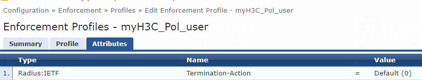
Verifying the configuration
1. On the ClearPass server, view user access request details:
# From the left navigation pane, select Monitoring > Live Monitoring > Access Tracker.
# On the page that opens, view the access request record and verify that the client has passed 802.1X or MAC authentication and come online. To view details of the access request record, click the access request record.
Figure 120 Viewing access request details
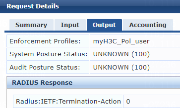
2. On the switch, verify that the online 802.1X or MAC authentication user is correctly assigned the termination action information.
# Use the display dot1x connection command to display information about online 802.1X authentication users.
[Device] display dot1x connection
Total connections: 1
Slot ID: 1
User MAC address: 0cda-411d-62f6
Access interface: Ten-GigabitEthernet1/0/49
Username: user
User access state: Successful
Authentication domain: bbb
Authentication method: EAP
Initial VLAN: 144
Authorization untagged VLAN: N/A
Authorization tagged VLAN list: N/A
Authorization ACL number/name: N/A
Authorization dynamic ACL name: N/A
Authorization user profile: N/A
Authorization CAR: N/A
Authorization URL: N/A
Termination action: Default
Session timeout period: N/A
Online from: 2022/05/12 14:09:59
Online duration: 0h 0m 5s
The output shows that the Termination-Action attribute has been successfully assigned to the user.
# Use the display mac-authentication connection command to display information about online MAC authentication users.
[Device]display mac-authentication connection
Total connections: 1
Slot ID: 1
User MAC address: 0cda-411d-62f6
Access interface: Ten-GigabitEthernet1/0/49
Username: user
User access state: Successful
Authentication domain: mac-auth
IPv6 address: FE80::5D79:AE17:4AEF:503A
Initial VLAN: 144
Authorization untagged VLAN: N/A
Authorization tagged VLAN: N/A
Authorization ACL number/name: N/A
Authorization dynamic ACL name: N/A
Authorization user profile: N/A
Authorization CAR: N/A
Authorization URL: N/A
Termination action: Default
Session timeout period: N/A
Online from: 2022/05/13 15:06:31
Online duration: 0h 0m 7s
The output shows that the Termination-Action attribute has been successfully assigned to the user.
3. Capture packets to verify that the switch reauthenticates the online 802.1X or MAC user at the periodic reauthentication interval to keep the user online.
Figure 121 Periodic 802.1X reauthentication
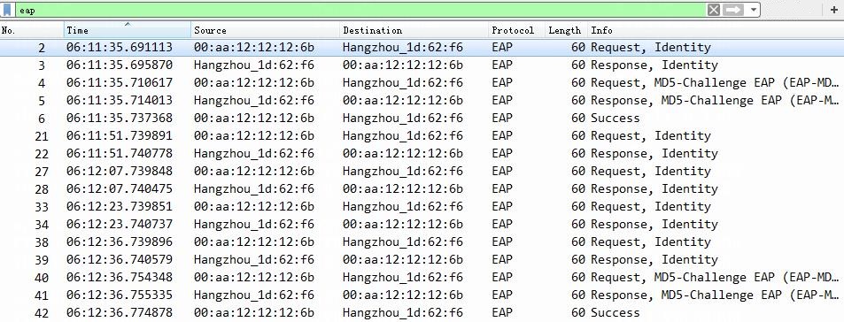
Figure 122 Periodic MAC reauthentication
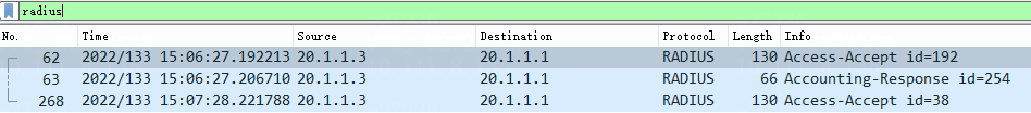
The output shows that the switch reauthenticated the online 802.1X or MAC user at the periodic reauthentication interval to keep the user online.
Example: Integrating the switch with ClearPass for authentication at a redirect URL
Network configuration
As shown in Figure 123, configure the switch to work in conjunction with a ClearPass server to do 802.1X authentication for the client connected to Ten-GigabitEthernet 1/0/49. The client must pass 802.1X authentication to access network resources.
Configure the switch as follows:
· Use the ClearPass server as both the RADIUS server and the portal server.
· Use 802.1X authentication.
· Configure the ClearPass server to assign a redirect URL to the client.
The switch will redirect the client user to the assigned URL for authentication when the user enters a random IP address in the Web browser after passing 802.1X authentication.

Software versions used
This configuration example was created and verified on the following hardware and software versions:
|
Hardware |
Software version |
|
H3C S5130-HI switch |
R3507P02 |
|
Aruba ClearPass server |
Aruba ClearPass Policy Manager (CPPM) v6.9.7 |
Procedures
Prerequisites
This example provides only the configuration for authentication. Make sure that the client, switch, and server have network connectivity to communicate with one another.
Configuring the switch
1. Configure the switch as described in "Example: Integrating the switch with ClearPass for 802.1X CHAP authentication."
2. Create advanced ACL rule 3100 to permit all packets destined for 20.1.1.3.
[Device] acl advanced 3100
[Device-acl-ipv4-adv-3100] rule 1 permit ip destination 20.1.1.3 0
Configuring the ClearPass server
Configure the ClearPass server as described in "Example: Integrating the switch with ClearPass for 802.1X CHAP authentication."
For authentication through a redirect URL, you must modify the attribute settings on the Attributes tab for the enforcement profile, as follows:
· Specify the redirect URL. Select Radius:H3C from the type list, select H3C-AVPair from the name list, and set the attribute value to url-redirect=https://IP address of the portal server/guest/h3c.php?_browser=1. In this example, the IP address of the portal server is 20.1.1.3.
· Specify the ACL number for filtering. Select Radius:H3C from the type list, select Filter-Id from the name list, and set the attribute value. In this example, set the attribute value to 3100.
Figure 124 Specifying attribute parameters in the enforcement profile
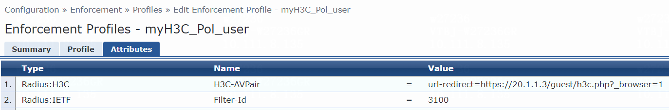
Verifying the configuration
1. On the ClearPass server, view user access request details:
# From the left navigation pane, select Monitoring > Live Monitoring > Access Tracker.
# On the page that opens, view the access request record and verify that the client has passed 802.1X authentication and come online. To view details of the access request record, click the access request record.
Figure 125 Viewing access request details
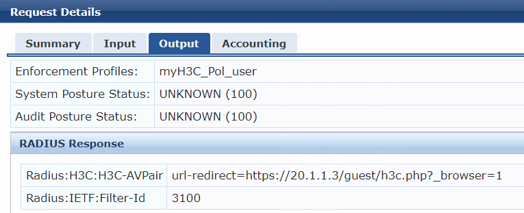
2. On the switch, verify that the authorization ACL rule and URL information are correctly configured for the online 802.1X authentication user.
# Use the display dot1x connection command to display information about online 802.1X authentication users.
[Device]display dot1x connection
Total connections: 1
Slot ID: 1
User MAC address: 0cda-411d-62f6
Access interface: Ten-GigabitEthernet1/0/49
Username: user
User access state: Successful
Authentication domain: bbb
Authentication method: CHAP
Initial VLAN: 144
Authorization untagged VLAN: N/A
Authorization tagged VLAN list: N/A
Authorization ACL number/name: 3100
Authorization dynamic ACL name: N/A
Authorization user profile: N/A
Authorization CAR: N/A
Authorization URL: https://20.1.1.3/guest/h3c.php?_browser=1
Termination action: Default
Session timeout period: N/A
Online from: 2022/05/27 11:16:21
Online duration: 0h 0m 4s
The output shows that the ACL rule and the redirect URL have been configured correctly for the user.
3. On the client, verify that you are redirected to the assigned URL for authentication after entering a random IP address in the Web browser. (Details not shown.)
Examples: Integrating the switch with ClearPass for authentication through RADIUS DAE
Network configuration
As shown in Figure 126, configure the switch to work in conjunction with a ClearPass server to do authentication for the client connected to Ten-GigabitEthernet 1/0/49. The client must pass authentication to access network resources. In the following examples, 802.1X authentication is used.
Configure the switch as follows:
· Use the ClearPass server as the RADIUS server to perform 802.1X authentication for the client.
· Configure the ClearPass server to send RADIUS DAE requests for the client.

Software versions used
This configuration example was created and verified on the following hardware and software versions:
|
Hardware |
Software version |
|
H3C S5130-HI switch |
R3507P02 |
|
Aruba ClearPass server |
Aruba ClearPass Policy Manager (CPPM) v6.9.7 |
Example: Forcing users offline by sending Disconnect Messages
Configuring the switch
1. Configure the switch as described in "Example: Integrating the switch with ClearPass for 802.1X CHAP authentication."
2. Enable the RADIUS DAE server (DAS), specify the ClearPass server as a DAE client (DAC), and set the shared key to 123456 in plaintext form.
[Device] radius dynamic-author server
[Device-radius-da-server] client ip 20.1.1.3 key simple 123456
[Device-radius-da-server] quit
Configuring the ClearPass server
Configure the ClearPass server as described in "Example: Integrating the switch with ClearPass for 802.1X CHAP authentication," except that you must add the following settings in this example:
On the Configuration > Enforcement > Profiles page, configure another enforcement profile as follows:
1. On the Profile tab, select RADIUS Dynamic Authorization from the Template list and set the name to myH3C_COA_Terminate Session.
Figure 127 Adding an enforcement profile
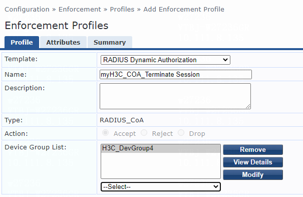
2. On the Attributes tab, specify attribute entries in the enforcement profile, as follows:
¡ Select Radius:IETF from the type list, select User-Name from the name list, and set the attribute value to %{Radius:IETF:User-Name}.
¡ Select Radius:IETF from the type list, select Calling-Station-Id from the name list, and set the attribute value to %{Radius:IETF:Calling-Station-Id}.
Figure 128 Specifying attribute parameters in the enforcement profile
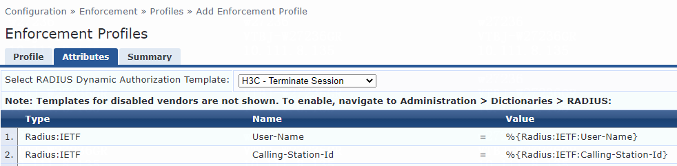
Verifying the configuration
On the ClearPass server, view user access request details before and after request messages disconnection:
1. From the left navigation pane, select Monitoring > Live Monitoring > Access Tracker.
2. On the page that opens, view the access request record and verify that the client has passed 802.1X authentication and come online. To view details of the access request record, click the access request record.
Figure 129 Viewing user online information
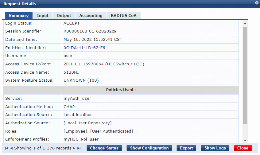
3. Click Change Status. On the page that opens, select RADIUS CoA as the access control type, select myH3C_COA_Terminate Session from the RADIUS CoA Type list, and then submit the configuration.
Figure 130 Changing the request status
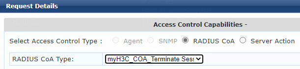
4. Click the RADIUS CoA tab to view RADIUS CoA details and click the Accounting tab to view session accounting information after the user goes offline.
Figure 131 Viewing RADIUS CoA details
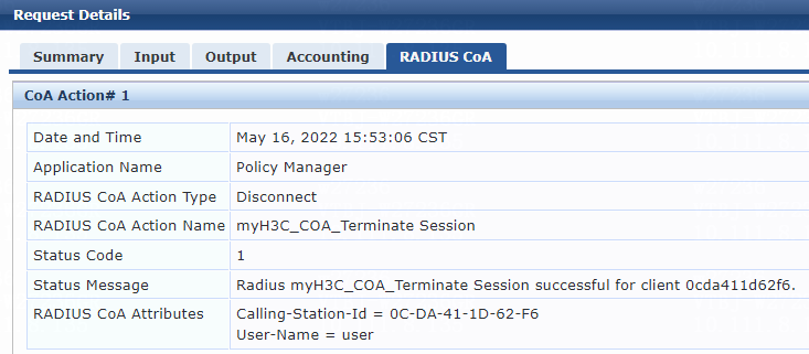
Figure 132 Viewing session accounting information
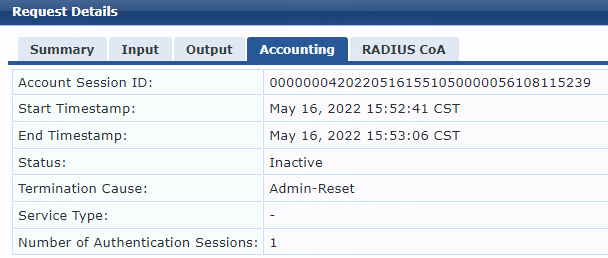
Example: Disabling the user-attached switch port
Configuring the switch
1. Configure the switch as described in "Example: Integrating the switch with ClearPass for 802.1X CHAP authentication."
2. Enable the RADIUS DAE server (DAS), specify the ClearPass server as a DAE client (DAC), and set the shared key to 123456 in plaintext form.
[Device] radius dynamic-author server
[Device-radius-da-server] client ip 20.1.1.3 key simple 123456
[Device-radius-da-server] quit
Configuring the ClearPass server
Configure the ClearPass server as described in "Example: Integrating the switch with ClearPass for 802.1X CHAP authentication," except that you must add the following settings in this example:
On the Configuration > Enforcement > Profiles page, configure another enforcement profile as follows:
1. On the Profile tab, select RADIUS Dynamic Authorization from the Template list and set the name to myH3C_COA_Disable Switch Port.
Figure 133 Adding an enforcement profile
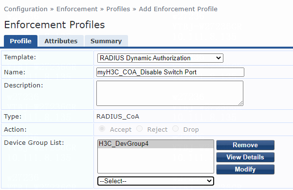
2. On the Attributes tab, add attribute entries in the enforcement profile, as follows:
¡ Select Radius:IETF from the type list, Calling-Station-Id from the name list, and set the attribute value to %{Radius:IETF:Calling-Station-Id}.
¡ Select Radius:H3C from the type list, H3C-AVPair from the name list, and set the attribute value to subscriber:command=disable-host-port.
Figure 134 Specifying attribute parameters in the enforcement profile

Verifying the configuration
On the ClearPass server, view user access request details before and after host port disabling:
1. From the left navigation pane, select Monitoring > Live Monitoring > Access Tracker.
2. On the page that opens, view the access request record and verify that the client has passed 802.1X authentication and come online. To view details of the access request record, click the access request record.
Figure 135 Viewing user online information
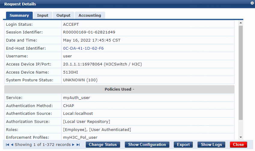
3. Click Change Status. On the page that opens, select RADIUS CoA as the access control type, select myH3C_COA_Disable Switch Port from the RADIUS CoA Type list, and then submit the configuration.
Figure 136 Changing the request status
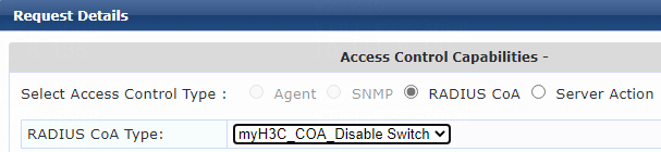
4. Click the RADIUS CoA tab to view RADIUS CoA details and click the Accounting tab to view session accounting information after the user goes offline.
Figure 137 Viewing RADIUS CoA details
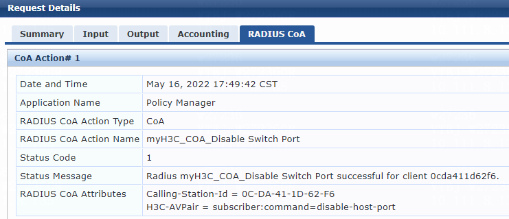
Figure 138 Viewing session accounting information
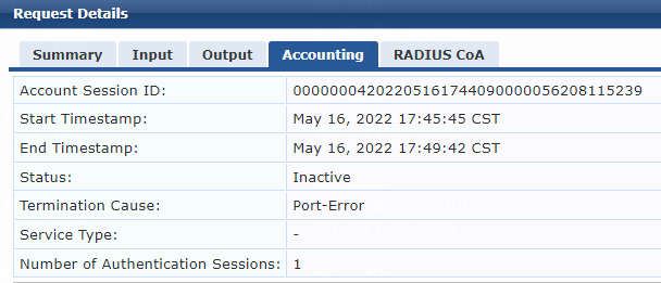
Example: Re-enabling the user-attached switch port
Configuring the switch
1. Configure the switch as described in "Example: Integrating the switch with ClearPass for 802.1X CHAP authentication."
2. Enable the RADIUS DAE server (DAS), specify the ClearPass server as a DAE client (DAC), and set the shared key to 123456 in plaintext form.
[Device] radius dynamic-author server
[Device-radius-da-server] client ip 20.1.1.3 key simple 123456
[Device-radius-da-server] quit
Configuring the ClearPass server
Configure the ClearPass server as described in "Example: Integrating the switch with ClearPass for 802.1X CHAP authentication," except that you must add the following settings in this example:
On the Configuration > Enforcement > Profiles page, configure another enforcement profile as follows:
1. On the Profile tab, select RADIUS Dynamic Authorization from the Template list and set the name to myH3C_COA_Bounce Switch Port.
Figure 139 Adding an enforcement profile
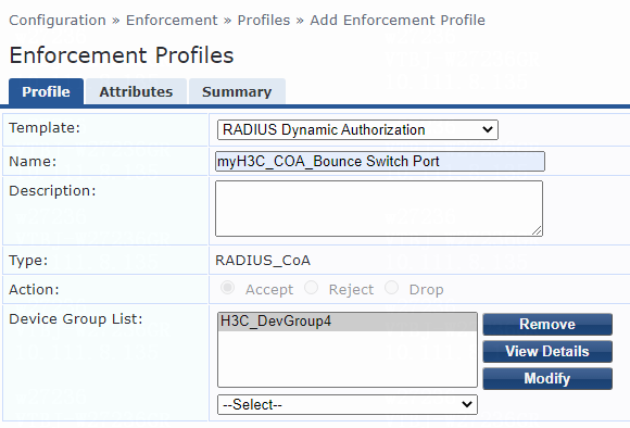
2. On the Attributes tab, add attribute entries in the enforcement profile, as follows:
¡ Select Radius:IETF from the type list, Calling-Station-Id from the name list, and set the attribute value to %{Radius:IETF:Calling-Station-Id}.
¡ Select Radius:H3C from the type list, H3C-AVPair from the name list, and set the attribute value to subscriber:command=bounce-host-port.
Figure 140 Specifying attribute parameters in the enforcement profile
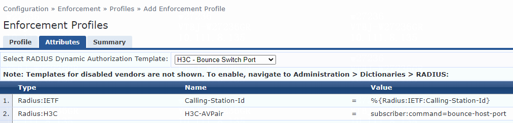
Verifying the configuration
On the ClearPass server, view user access request details before and after host port bouncing:
1. From the left navigation pane, select Monitoring > Live Monitoring > Access Tracker.
2. On the page that opens, view the access request record and verify that the client has passed 802.1X authentication and come online. To view details of the access request record, click the access request record.
Figure 141 Viewing user online information
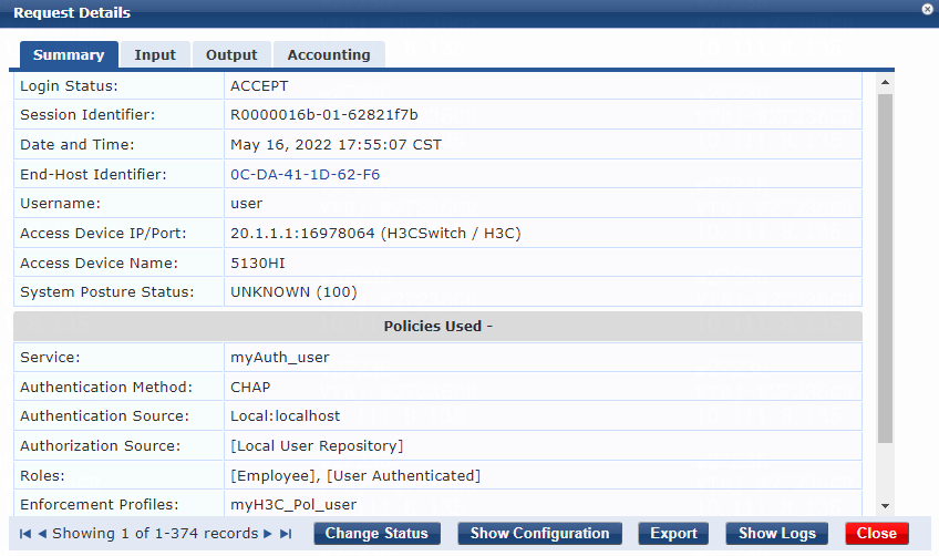
3. Click Change Status. On the page that opens, select RADIUS CoA as the access control type, select myH3C_COA_Bounce Switch Port from the RADIUS CoA Type list, and then submit the configuration.
Figure 142 Changing the request status
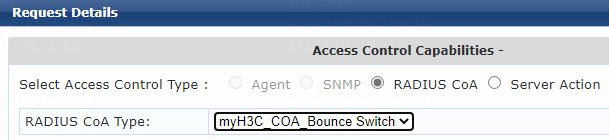
4. After the user goes offline due to port down, click the RADIUS CoA tab to view RADIUS CoA details and click the Accounting tab to view session accounting information.
Figure 143 Viewing RADIUS CoA details

Figure 144 Viewing session accounting information
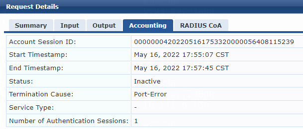
5. After the port comes up, click the Summary tab to view user online information and click the Accounting tab to view session accounting information.
Figure 145 Viewing user online information
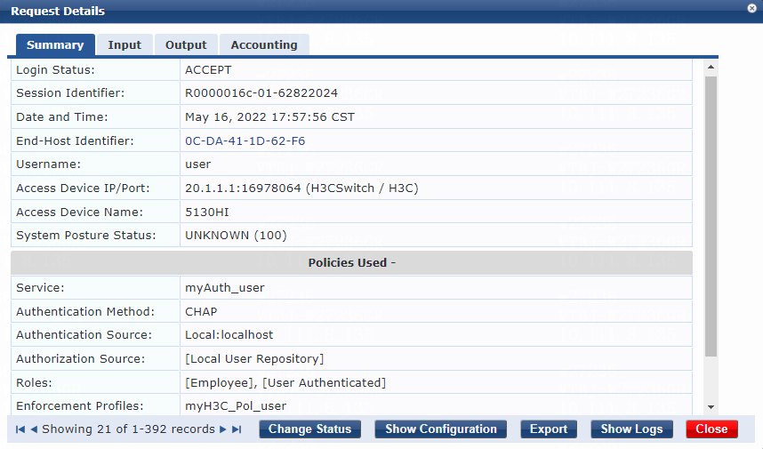
Figure 146 Viewing session accounting information
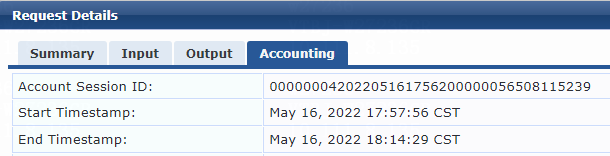
Example: Configuring HWTACACS authentication for SSH users that access the switch
Network configuration
As shown in Figure 147, configure the switch to work in conjunction with a ClearPass server to do HWTACACS authentication for the administrator connected to Ten-GigabitEthernet 1/0/49 to access the switch through SSH. In addition, assign the network-admin user role to the administrator.

Software versions used
This configuration example was created and verified on the following hardware and software versions:
|
Hardware |
Software version |
|
H3C S5130-HI switch |
R3507P02 |
|
Aruba ClearPass server |
Aruba ClearPass Policy Manager (CPPM) v6.9.7 |
Procedures
Configuring the switch
# Create an HWTACACS scheme named tac, specify the ClearPass server at 20.1.1.3 for user authentication and accounting, set the shared key to 123456 in plaintext form, and exclude domain names from the usernames sent to the HWTACACS server.
<Device> system-view
[Device] hwtacacs scheme tac
[Device-hwtacacs-tac] primary authentication 20.1.1.3
[Device-hwtacacs-tac] primary accounting 20.1.1.3
[Device-hwtacacs-tac] key authentication simple 123456
[Device-hwtacacs-tac] key accounting simple 123456
[Device-hwtacacs-tac] user-name-format without-domain
[Device-hwtacacs-tac] quit
# Create an ISP domain named tac and configure the domain to use the HWTACACS scheme for authentication, authorization, and accounting of login users.
[Device] domain tac
[Device-isp-tac] authentication login hwtacacs-scheme tac
[Device-isp-tac] authorization login hwtacacs-scheme tac
[Device-isp-tac] accounting login hwtacacs-scheme tac
[Device-isp-tac] quit
# Specify ISP domain tac as the default ISP domain.
[Device] domain default enable tac
# Create local RSA and DSA key pairs.
[Device] public-key local create rsa
[Device] public-key local create dsa
# Enable the SSH service.
[Device] ssh server enable
# Enable the default user role feature to assign authenticated SSH users the default user role network-admin.
[Device] role default-role enable network-admin
# Enable scheme authentication for user lines VTY 0 through VTY 63.
[Device] line vty 0 63
[Device-line-vty0-63] authentication-mode scheme
[Device-line-vty0-63] quit
# Create VLANs 144 and 145 and VLAN-interfaces 144 and 145, and assign IP addresses to the VLAN interfaces.
[Device] vlan 144
[Device-vlan144] quit
[Device] interface Vlan-interface 144
[Device-Vlan-interface144] ip address 101.0.145.19 255.255.255.0
[Device-Vlan-interface144] quit
[Device] vlan 145
[Device-vlan145] quit
[Device] interface Vlan-interface 145
[Device-Vlan-interface145] ip address 20.1.1.1 255.255.255.0
[Device-Vlan-interface145] quit
# Assign Ten-GigabitEthernet 1/0/49 to VLAN 144 and Ten-GigabitEthernet 1/0/51 to VLAN 145.
[Device] interface Ten-GigabitEthernet 1/0/49
[Device-Ten-GigabitEthernet1/0/49] port access vlan 144
[Device-Ten-GigabitEthernet1/0/49] quit
[Device] interface Ten-GigabitEthernet 1/0/51
[Device-Ten-GigabitEthernet1/0/51] port access vlan 145
[Device-Ten-GigabitEthernet1/0/51] quit
Configuring the ClearPass server
1. Log in to the ClearPass server:
# Enter the management IP address of the ClearPass server in the address bar of the Web browser.
Figure 148 Logging in to ClearPass

# Click ClearPass Policy Manager.
# On the page that opens, enter the login username and password, and then click Log In. In this example, the username and password are admin and Pass1234_, respectively.
Figure 149 Logging in to ClearPass Policy Manager
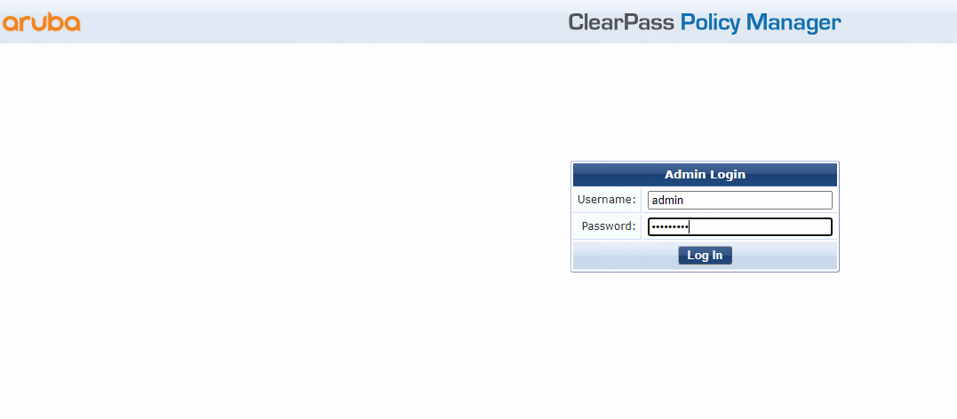
2. Add a user:
# From the left navigation pane, select Configuration > Identity > Local Users. On the page that opens, click Add in the upper right corner.
# Configure the user account:
a. Set the user ID and name.
b. Set the password and then verify the password.
c. Select the Enable User option to enable the user account.
d. Select predefined role Employee or a user-defined role. In this example, predefined role Employee is selected.
e. Click Add.
Figure 150 Adding a user
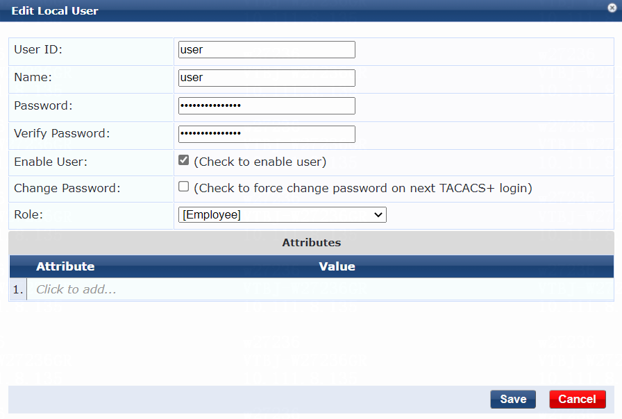
3. Configure a role mapping:
# From the left navigation pane, select Configuration > Identity > Role Mappings.
# On the Policy tab, click Add in the upper right corner.
# Add a role mapping policy:
a. Specify the policy name. In this example, myrole_user_tacacs is used.
b. Specify the default role as [Employee].
# Click Next to open the Mapping Rules tab, and then click Add Rule.
# On the page that opens, select the Select first match option for the Rules Evaluation Algorithm field and specify a mapping rule:
a. Select type Tacacs.
b. Select name UserName.
c. Select operator EQUALS.
d. Enter the user ID you have specified in the Value field. In this example, the user ID is user.
e. Select role name [Employee].
f. Click Save.
Figure 151 Role mapping summary
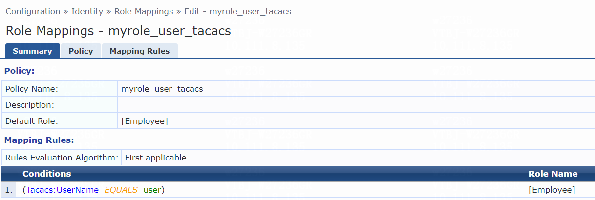
4. Add the switch to ClearPass Policy Manager:
# From the left navigation pane, select Configuration > Network > Devices. On the page that opens, click Add in the upper right corner.
# Add the switch:
a. Specify the name of the switch. In this example, H3CSwitch is used.
b. Specify the IP address of the switch, for example, 20.1.1.1.
Make sure the ClearPass server can reach this IP address.
c. (Optional.) Enter a description of the switch for management purposes. In this example, 5130HI is used.
d. Configure the TACACS shared secret and then verify the shared secret.
Make sure the shared secret specified on the server is the same as the shared key specified on the switch for TACACS authentication. In this example, 123456 is used.
e. Select vendor name H3C.
f. Enable RADIUS dynamic authorization (the default port is 3799).
g. Click Add.
Figure 152 Adding a device

5. Add a device group:
# From the left navigation pane, select Configuration > Network > Device Groups.
# On the page that opens, click Add in the upper right corner.
# Configure the device group:
a. Specify the name of the device group. In this example, H3C_DevGroup4 is used.
b. (Optional.) Enter a description of the device group for management purposes. In this example, net is used.
c. Select format Subnet.
d. Specify a subnet in network_address/mask_length format (CIDR notation).
Make sure the ClearPass server can reach this subnet. In this example, 20.1.1.1/24 is used.
e. Click Save.
Figure 153 Adding a device group
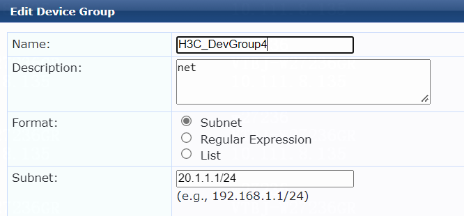
6. Add an enforcement profile:
# From the left navigation pane, select Configuration > Enforcement > Profiles.
# On the page that opens, click Add in the upper right corner.
# Add the enforcement profile:
a. On the Profile tab, select TACACS+ Based Enforcement from the Template list and set the name to myH3C_Tacacs.
b. (Optional.) Enter a description of the profile.
c. Set the action to Accept.
d. Select device group H3C_DevGroup4 from the device group list.
# Click Next to open the Services tab, and then specify the following services parameters:
a. Set the privilege level to 15.
b. Select Shell in the Selected Services field.
c. Select ADD in the Authorize Attribute Status field.
# Click Next to open the Commands tab, and then specify commands parameters:
a. Select Enable to permit unmatched commands to permit unmatched records (Shell is automatically selected in the Service Type field).
b. Click Save.
Figure 154 Enforcement profile summary
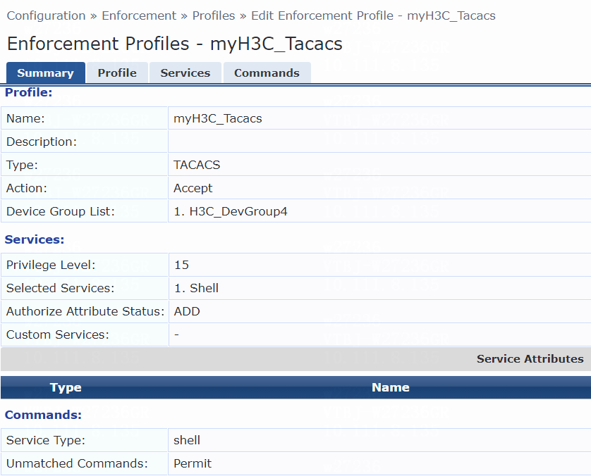
7. Add an enforcement policy:
# From the left navigation pane, select Configuration > Enforcement > Policies.
# On the Enforcement tab, click Add in the upper right corner.
# Configure the policy:
a. Set the policy name to myH3CPolicy_tacacs.
b. (Optional.) Enter a description of the enforcement policy for management purposes.
c. Select enforcement type TACACS.
d. Select [TACACS Deny Profile] as the default profile.
# Click Next to open the Rules tab, and then click Add Rule.
# On the page that opens, select a rules evaluation algorithm for the Rules Evaluation Algorithm field. In this example, Select first match is used. Then, specify the following enforcement policy rules parameters:
a. Select type Tips.
b. Select name Role.
c. Select operator MATCHES_ALL.
d. Select value [Employee].
e. Select enforcement profile myH3C_Tacacs.
f. Click Save.
Figure 155 Enforcement policy summary
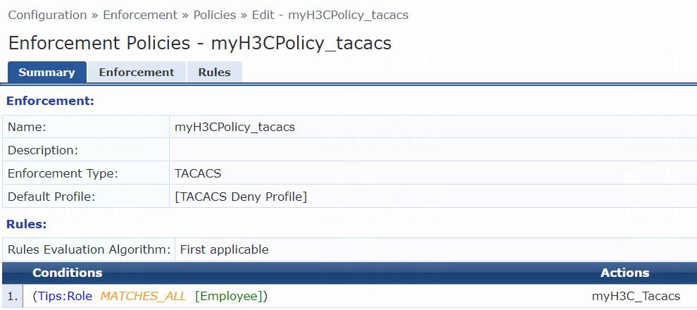
8. Add a service:
# From the left navigation pane, select Configuration > Services. On the page that opens, click Add in the upper right corner.
# On the Service tab, configure the service parameters:
a. Select TACACS+ Enforcement from the Type list.
b. Set the name to myAuth_Tacacs.
c. Select ANY of the following conditions for the Matches field.
d. Configure a rule to match services. In the rule, set the type to Connection, name to Protocol, operator to EQUALS, and value to TACACS.
e. Click Save.
Figure 156 Adding a service
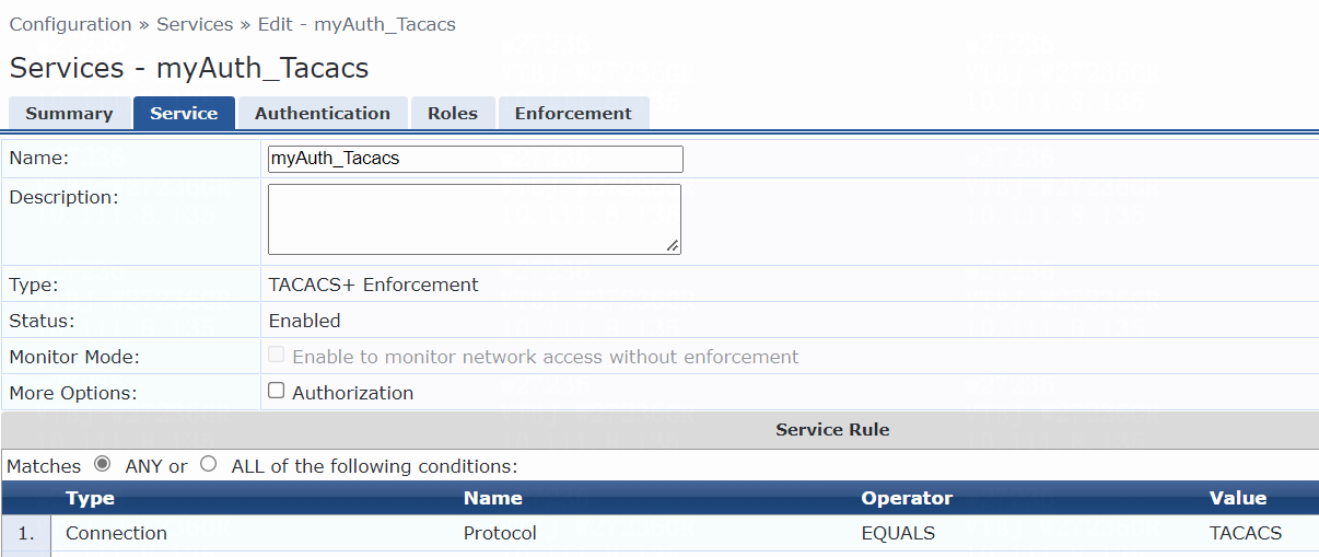
# On the Authentication tab, select [Local User Repository][Local SQL DB] from the Authentication Sources list.
Figure 157 Configuring authentication
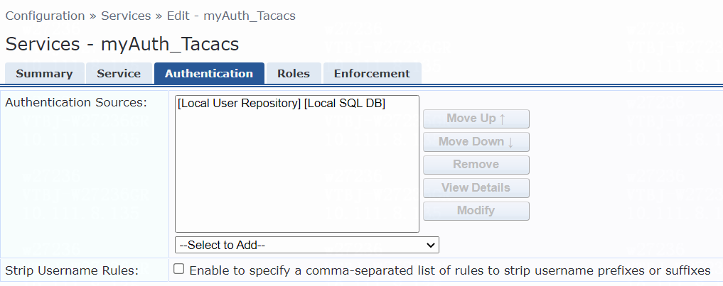
# On the Roles tab, select myrole_user_tacacs from the Role Mapping Policy list, and then click Save.
Figure 158 Configuring roles
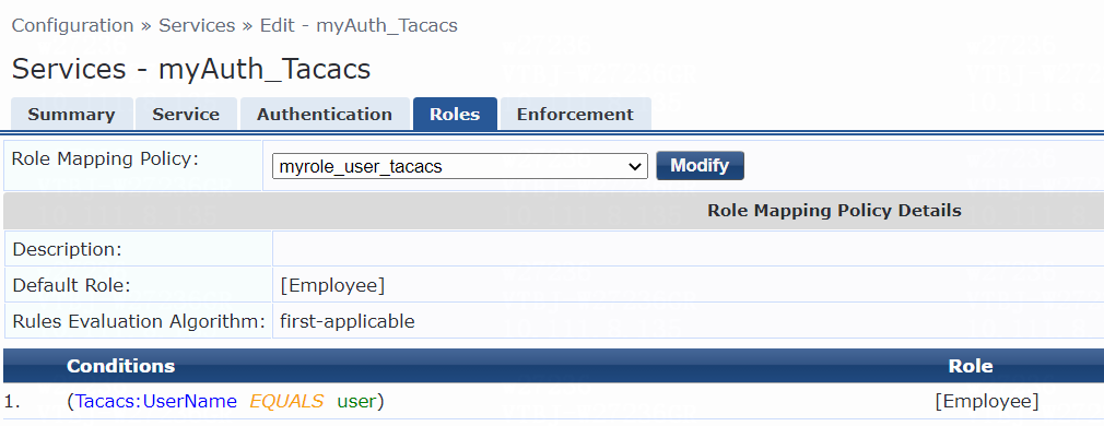
# On the Enforcement tab, select enforcement policy myH3CPolicy_tacacs, and then click Save.
Figure 159 Configuring enforcement
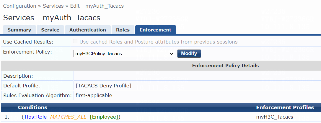
Verifying the configuration
1. On the client, verify that the user can establish a connection to the switch:
a. Launch PuTTY.exe to open the PuTTY Configuration window.
b. Click Session.
c. Select connection type SSH.
d. Enter the IP address of the device to be accessed in the Host Name (or IP address) field.
Make sure the IP address can reach the client. In this example, 101.0.145.19 is used.
e. Use the default port 22.
f. Click Open.
Figure 160 Specifying PuTTY configuration parameters
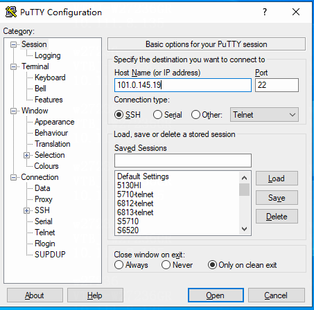
g. Enter username user and password 123456 to log in to the switch. (Details not shown.)
2. On the ClearPass server, view TACACS+ session details:
# From the left navigation pane, select Monitoring > Live Monitoring > Access Tracker.
# On the page that opens, view the TACACS+ session record and verify that the client has passed HWTACACS authentication and come online. To view details of the TACACS+ session record, click the TACACS+ session record.
Figure 161 Viewing TACACS+ session summary
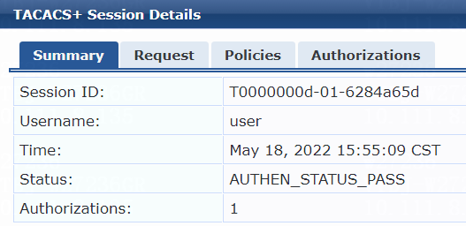
Figure 162 Viewing TACACS+ session policies
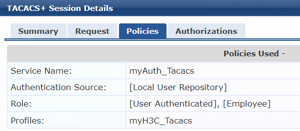
Figure 163 Viewing TACACS+ session authorizations
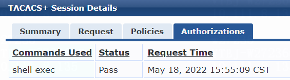
Example: Configuring RADIUS authentication for users that access the switch through SSH, Telnet, or the console port
Network configuration
As shown in Figure 164, configure the switch to work in conjunction with a ClearPass server to do RADIUS authentication for the administrator connected to Ten-GigabitEthernet 1/0/49 to access the switch. In addition, assign the network-admin user role to the administrator.

Software versions used
This configuration example was created and verified on the following hardware and software versions:
|
Hardware |
Software version |
|
H3C S5130-HI switch |
R3507P02 |
|
Aruba ClearPass server |
Aruba ClearPass Policy Manager (CPPM) v6.9.7 |
Procedures
Configuring the switch
Configuring access control settings for SSH users
# Create a RADIUS scheme named radius1, specify the ClearPass server at 20.1.1.3 for user authentication and accounting, set the shared key to 123456 in plaintext form, and exclude domain names from the usernames sent to the RADIUS server.
<Device> system-view
[Device] radius scheme radius1
[Device-radius-radius1] primary authentication 20.1.1.3
[Device-radius-radius1] primary accounting 20.1.1.3
[Device-radius-radius1] key authentication simple 123456
[Device-radius-radius1] key accounting simple 123456
[Device-radius-radius1] user-name-format without-domain
[Device-radius-radius1] quit
# Create an ISP domain named 123 and apply the RADIUS scheme to the ISP domain for authentication, authorization, and accounting.
[Device] domain 123
[Device-isp-123] authentication login radius-scheme radius1
[Device-isp-123] authorization login radius-scheme radius1
[Device-isp-123] accounting login radius-scheme radius1
[Device-isp-123] quit
# Specify ISP domain 123 as the default ISP domain.
[Device] domain default enable 123
# Create local RSA and DSA key pairs.
[Device] public-key local create rsa
[Device] public-key local create dsa
# Enable the SSH service.
[Device] ssh server enable
# Enable scheme authentication for user lines VTY 0 through VTY 63.
[Device] line vty 0 63
[Device-line-vty0-63] authentication-mode scheme
[Device-line-vty0-63] quit
# Create VLANs 144 and 145 and VLAN-interfaces 144 and 145, and assign IP addresses to the VLAN interfaces.
[Device] vlan 144
[Device-vlan144] quit
[Device] interface Vlan-interface 144
[Device-Vlan-interface144] ip address 101.0.145.19 255.255.255.0
[Device-Vlan-interface144] quit
[Device] vlan 145
[Device-vlan145] quit
[Device] interface Vlan-interface 145
[Device-Vlan-interface145] ip address 20.1.1.1 255.255.255.0
[Device-Vlan-interface145] quit
# Assign Ten-GigabitEthernet 1/0/49 to VLAN 144 and Ten-GigabitEthernet 1/0/51 to VLAN 145.
[Device] interface Ten-GigabitEthernet 1/0/49
[Device-Ten-GigabitEthernet1/0/49] port access vlan 144
[Device-Ten-GigabitEthernet1/0/49] quit
[Device] interface Ten-GigabitEthernet 1/0/51
[Device-Ten-GigabitEthernet1/0/51] port access vlan 145
[Device-Ten-GigabitEthernet1/0/51] quit
Configuring access control settings for Telnet users
Configure the switch as described in "Configuring access control settings for SSH users" except that you must add the following configuration:
# Enable the Telnet service.
[Device] telnet server enable
Configuring access control settings for console login users
Configure the switch as described in "Configuring access control settings for SSH users" except that you must add the following configuration:
# Enable scheme authentication for user lines VTY 0 through VTY 63.
[Device] line aux 0
[Device-line-aux0] authentication-mode scheme
[Device-line-aux0] quit
Configuring the ClearPass server
Configure the ClearPass server as described in "Example: Integrating the switch with ClearPass for 802.1X CHAP authentication," except that you must modify the attribute settings in this example, as follows:
On the Attributes tab, select Radius:H3C from the type list, select H3C-AVPair from the name list, and set the attribute value to shell:roles=netwok-admin.
|
|
IMPORTANT: The user role name contained in the value must be a role supported on the switch. To view supported user roles, execute the display role command in system view on the switch. |
Figure 165 Specifying attribute parameters in the enforcement profile
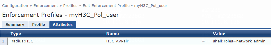
Verifying the configuration
Verifying SSH or Telnet access
1. On the client, verify that the user can establish a connection to the switch:
a. Launch PuTTY.exe to open the PuTTY Configuration window.
b. Click Session.
c. Select a connection type.
- Select SSH for SSH connection.
- Click Other and select Telnet for Telnet connection.
d. Enter the IP address of the device to be accessed in the Host Name (or IP address) field.
Make sure the IP address can reach the client. In this example, 101.0.145.19 is used.
e. Enter the port.
- Use port 22 for SSH connection.
- Use port 23 for Telnet connection.
f. Click Open.
Figure 166 Specifying PuTTY configuration parameters for SSH connection

Figure 167 Specifying PuTTY configuration parameters for Telnet connection
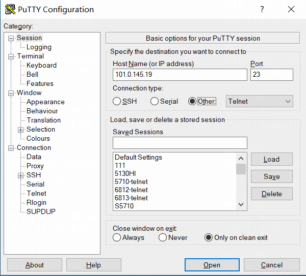
g. Enter username user and password 123456 to log in to the switch.
2. On the ClearPass server, view user access request details:
# From the left navigation pane, select Monitoring > Live Monitoring > Access Tracker.
# On the page that opens, view the access request record and verify that the client has passed RADIUS authentication and come online. To view details of the access request record, click the access request record.
Figure 168 Viewing access request details
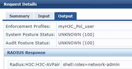
Verifying console access
1. On the client, verify that you can establish a connection to the switch through the console port by entering username user and password 123456.
2. On the ClearPass server, view TACACS+ session details:
# From the left navigation pane, select Monitoring > Live Monitoring > Access Tracker.
# On the page that opens, view the access request record and verify that the client has passed RADIUS authentication and come online. To view details of the access request record, click the access request record.
Figure 169 Viewing access request details

