- Table of Contents
- Related Documents
-
| Title | Size | Download |
|---|---|---|
| 02-Windows Server 2016-NPS Authentication Server Integration Guide | 7.98 MB |
|
|
|
H3C Switches and Windows Server 2016 NPS |
|
Authentication Server Integration Guide |
|
|
|
|
Copyright © 2023 New H3C Technologies Co., Ltd. All rights reserved.
No part of this manual may be reproduced or transmitted in any form or by any means without prior written consent of New H3C Technologies Co., Ltd.
Except for the trademarks of New H3C Technologies Co., Ltd., any trademarks that may be mentioned in this document are the property of their respective owners.
The information in this document is subject to change without notice.
H3C switches and Windows Server 2016 NPS compatibility in authentication methods
Examples: Configuring MAC authentication
Example: Configuring MAC authentication with a shared user account
Example: Configuring MAC authentication with MAC-based user accounts
Configuring the Windows Server 2016 NPS server
Examples: Configuring 802.1X authentication
Example: Configuring 802.1X CHAP authentication
Example: Configuring 802.1X PAP authentication
Example: Configuring 802.1X EAP-PEAP authentication
Example: Configuring local portal authentication through the LDAP server
Examples: Configuring 802.1X or MAC authentication with VLAN assignment
Example: Configuring 802.1X or MAC authentication with VLAN ID assignment
Example: Configuring 802.1X or MAC authentication with VLAN name assignment
Example: Configuring 802.1X or MAC authentication with VLAN group assignment
Example: Configuring 802.1X or MAC authentication with multiple VLANs assignment
Example: Configuring 802.1X authentication with automatic assignment of only tagged VLANs
Example: Configuring 802.1X authentication with assignment of VLANs that contain one untagged VLAN
Example: Configuring 802.1X or MAC authentication with ACL assignment
Example: Configuring 802.1X or MAC authentication with user profile assignment
Introduction
This document provides examples for integrating H3C switches with a Windows Server 2016 NPS server for user access authentication. This document provides examples for the following authentication and authorization features:
· MAC authentication.
· 802.1X authentication.
· Portal authentication.
· Authorization VLAN assignment.
· Authorization ACL assignment.
· Authorization user profile assignment.
Support for the authentication and authorization features depends on the device model. For more information, see the security configuration guide for your switch.
H3C switches and Windows Server 2016 NPS compatibility in authentication methods
|
H3C switches |
Windows Server 2016 NPS |
Compatibility |
|
MAC authentication with a shared user account |
CHAP authentication |
Yes |
|
MAC authentication with MAC-based user accounts |
CHAP authentication |
Yes |
|
802.1X CHAP authentication |
CHAP authentication |
Yes |
|
802.1X PAP authentication |
PAP authentication |
Yes |
|
802.1X EAP authentication |
EAP-PEAP authentication |
Yes |
|
Local portal + LDAP authentication |
CHAP authentication |
Yes |
|
Authorization VLAN |
· VLAN ID authorization · VLAN name authorization · VLAN group name authorization · Multi-VLAN authorization · Auto VLAN authorization (VLAN authorization with the tag attribute) |
Yes |
|
Authorization ACL |
Authorization static ACL |
Yes |
|
Authorization user profile |
Authorization user profile |
Yes |
Prerequisites
The following information applies to H3C switches. Procedures and information in the examples might be slightly different depending on the software or hardware version of the switch and the software version of the Windows Server 2016 NPS server.
The configuration examples were created and verified in a lab environment, and all the devices were started with the factory default configuration. When you are working on a live network, make sure you understand the potential impact of every configuration item on your network.
Examples: Configuring MAC authentication
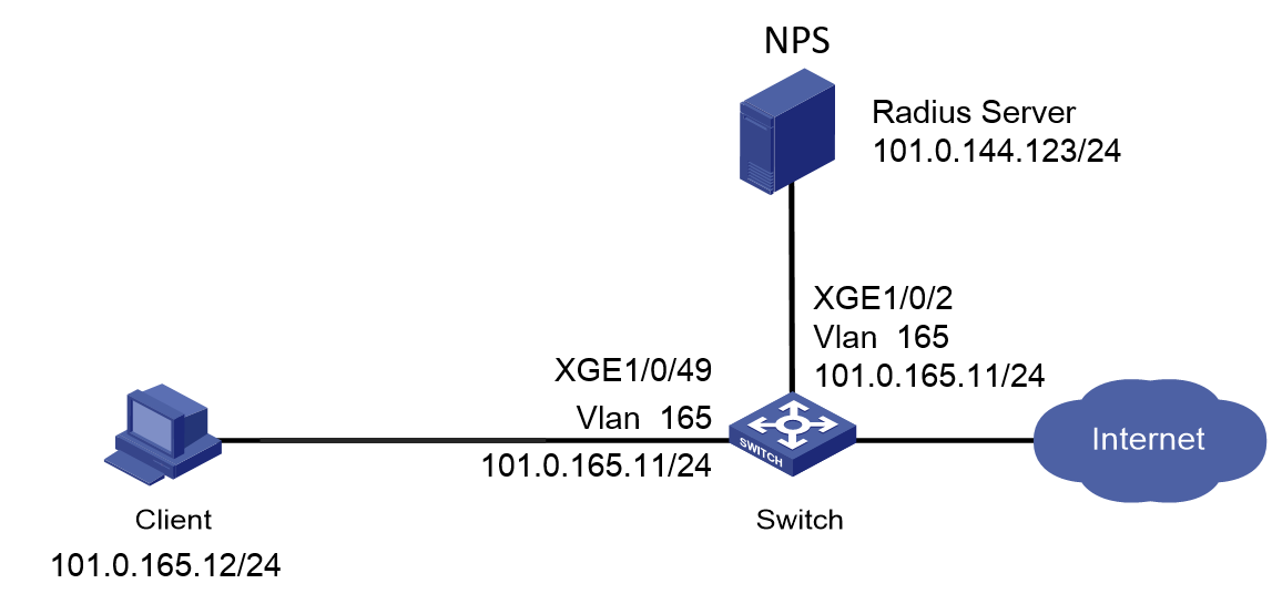
Network configuration
As shown in Figure 1, configure the switch to work in conjunction with the Windows Server 2016 NPS server to perform MAC authentication on the client. The client must pass MAC authentication to access network resources.
Configure the switch as follows:
· Use the NPS server as the RADIUS server to perform MAC authentication for the client.
· Create a shared account with the specified username and password for all MAC authentication users, or use the MAC address of the client as the username and password for MAC authentication.

Software versions used
This configuration example was created and verified on the following hardware and software versions:
|
Hardware |
Software version |
|
S5560X-54C-PWR-EI switch |
Version 7.1.070 |
|
Authentication server |
Windows Server 2016 NPS |
Example: Configuring MAC authentication with a shared user account
Prerequisites
This example provides only the configuration for authentication. Make sure that the client, switch, and server have network connectivity to communicate with one another.
Configuring the switch
# Create RADIUS scheme radius1, specify the NPS server at 101.0.144.123 for user authentication and accounting, set the shared key to admin in plaintext form, and exclude domain names from usernames sent to the RADIUS server.
<Switch> system-view
[Switch] radius scheme radius1
[Switch-radius-radius1] primary authentication 101.0.144.123
[Switch-radius-radius1] primary accounting 101.0.144.123
[Switch-radius-radius1] key authentication simple admin
[Switch-radius-radius1] key accounting simple admin
[Switch-radius-radius1] user-name-format without-domain
[Switch-radius-radius1] quit
# Configure the switch to use CHAP for MAC authentication.
[Switch] mac-authentication authentication-method chap
# Create ISP domain mac-auth and apply the RADIUS scheme to the ISP domain for authentication, authorization, and accounting.
[Switch] domain mac-auth
[Switch-isp-mac-auth] authentication default radius-scheme radius1
[Switch-isp-mac-auth] authorization default radius-scheme radius1
[Switch-isp-mac-auth] accounting default radius-scheme radius1
[Switch-isp-mac-auth] quit
# Create VLAN 165 and VLAN-interface 165, and assign an IP address to the VLAN interface.
[Switch] vlan 165
[Switch-vlan165] quit
[Switch] interface Vlan-interface 165
[Switch-Vlan-interface165] ip address 101.0.165.11 255.255.255.0
[Switch-Vlan-interface165] quit
# Assign Ten-GigabitEthernet 1/0/49 to VLAN 165 and enable MAC authentication on Ten-GigabitEthernet 1/0/49.
[Switch]interface Ten-GigabitEthernet 1/0/49
[Switch-Ten-GigabitEthernet1/0/49] port access vlan 165
[Switch-Ten-GigabitEthernet1/0/49] mac-authentication
[Switch-Ten-GigabitEthernet1/0/49] quit
# Specify ISP domain mac-auth as the default ISP domain.
[Switch] domain default enable mac-auth
# Specify ISP domain mac-auth as the MAC authentication domain.
[Switch] mac-authentication domain mac-auth
# Configure the offline detection and quiet timers for MAC authentication.
[Switch] mac-authentication timer offline-detect 180
[Switch] mac-authentication timer quiet 180
# Specify username user and password 123456 in plaintext form for the account shared by MAC authentication users.
[Switch] mac-authentication user-name-format fixed account user password simple 123456
# Enable MAC authentication globally.
[Switch] mac-authentication
Configuring the Windows Server 2016 NPS server
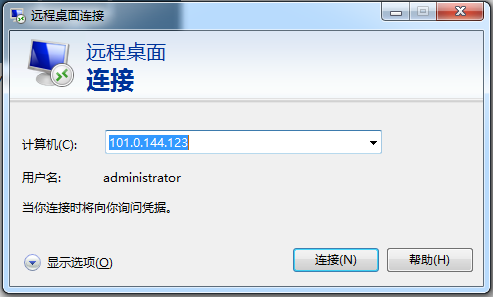
1. Log in to the Windows Server 2016 NPS server:
# Open Remote Desktop Connection on the client, enter the management IP address of the NPS server in the Computer filed, and then click Connect.
In this example, the computer IP address is 101.0.144.123.
Figure 2 Remote desktop connection
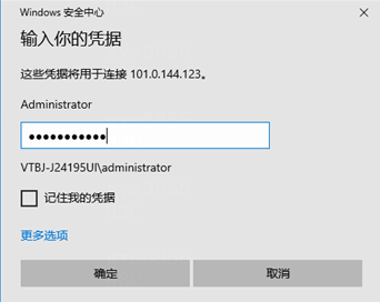
# On the window that opens, enter the username and password for logging in to the NPS server, and then click OK.
In this example, the username and password are Administrator and admin@123456, respectively.
Figure 3 Entering login username and password
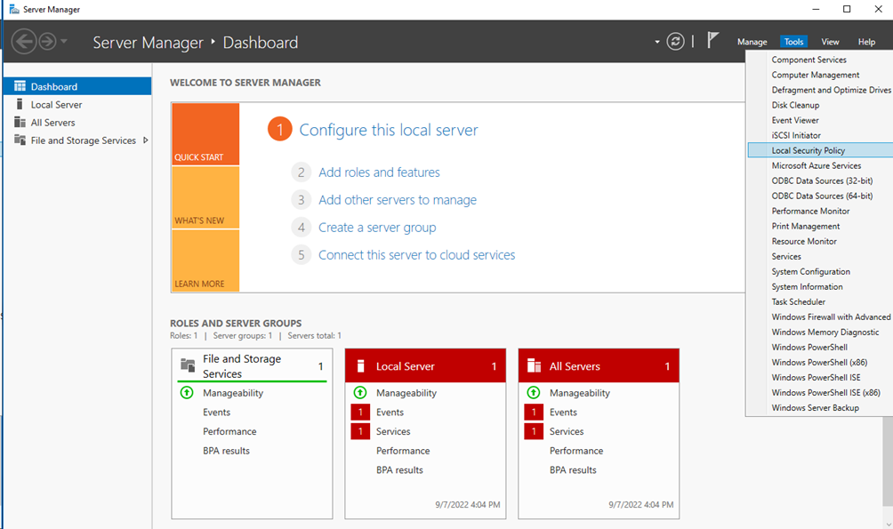
2. Configure a local security policy:
# On the Server Manager Dashboard, select Tools > Local Security Policy.
Figure 4 Configuring a local security policy
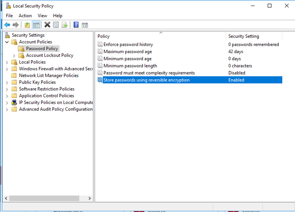
# On the Local Security Policy window that opens, select Password Policy in the left navigation pane. Set Disabled for the Password must meet complexity requirements field and Enabled for the Store passwords using reversible encryption field.
Figure 5 Configuring the password policy
3. Add roles and features:
# On the Server Manager Dashboard, select Manage > Add Roles and Features.
Figure 6 Adding roles and features

# On the Add Roles and Features Wizard, select Installation Type in the left navigation pane, and then select Role-based or feature-based installation.
Figure 7 Selecting the installation type

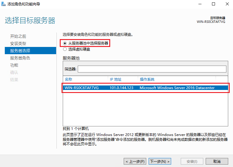
# Click Next. On the Server Selection pane, select Select a server from the server pool. Make sure the server that you have logged in to is in the server pool list.
Figure 8 Selecting the destination server
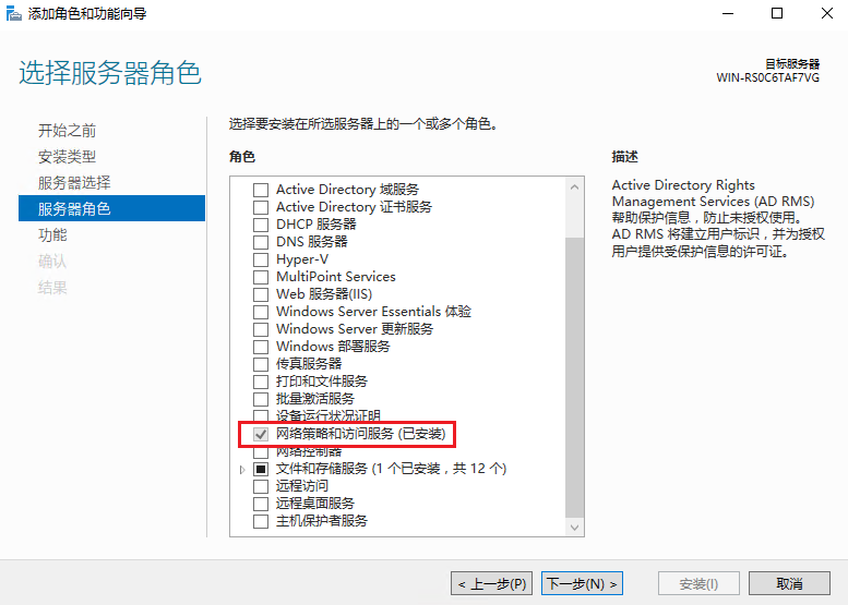
# Click Next. On the Server Roles pane, select Network Policy and Access Services, and then click Next. Complete the installation according to the prompt.
Figure 9 Selecting the server roles
4. Configure the RADIUS client:
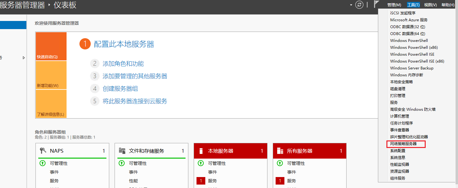
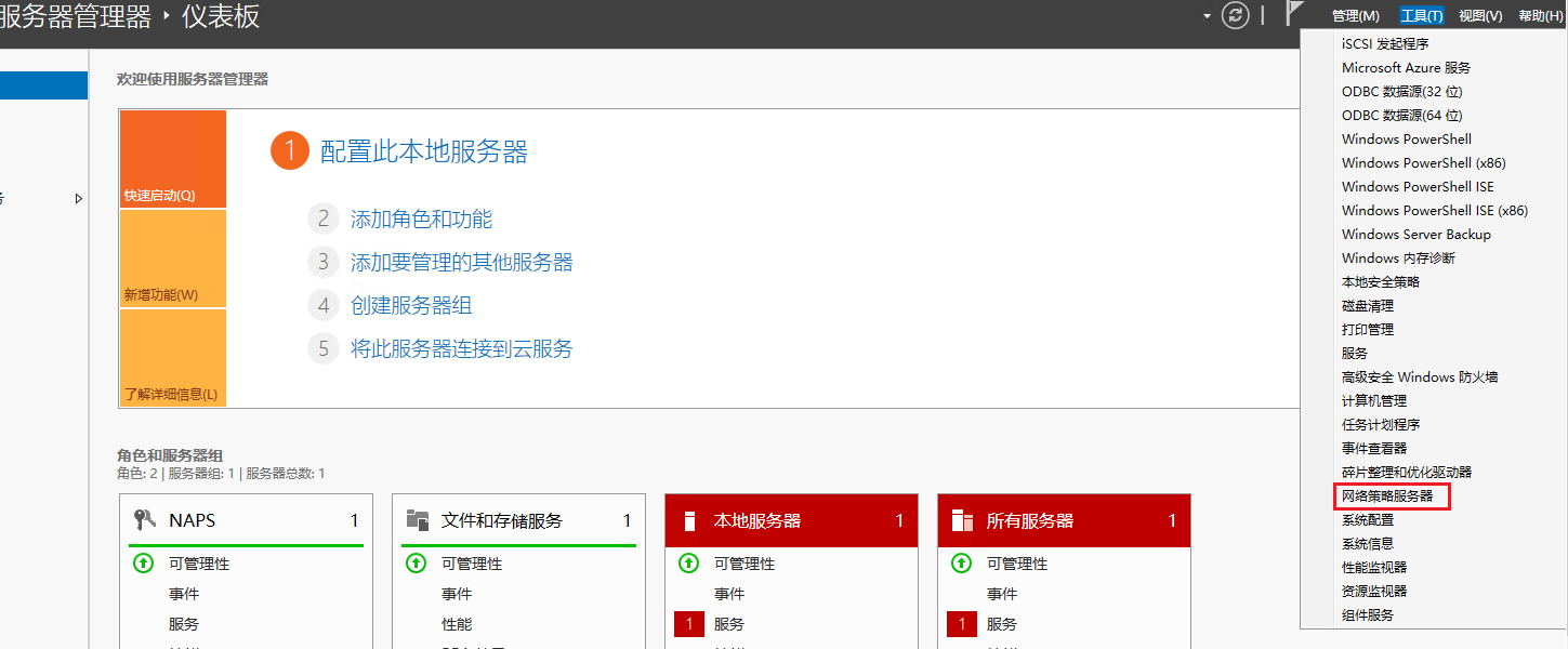
# On the Server Manager Dashboard, select Tools > Network Policy Server.
Figure 10 Opening the network policy server configuration window
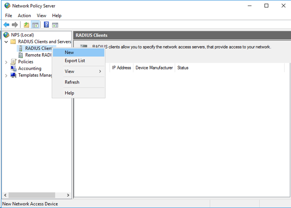
# In the left navigation pane, select RADIUS Client and Servers > RADIUS Clients. Right-click RADIUS Clients and then select New to create a RADIUS client.
Figure 11 Creating a RADIUS client
# On the window that opens, specify the friendly name, address, and shared secret for the RADIUS client. Make sure the shared secret is the same as the shared key configured for the primary authentication and accounting server on the switch.
Figure 12 Configuring the RADIUS client
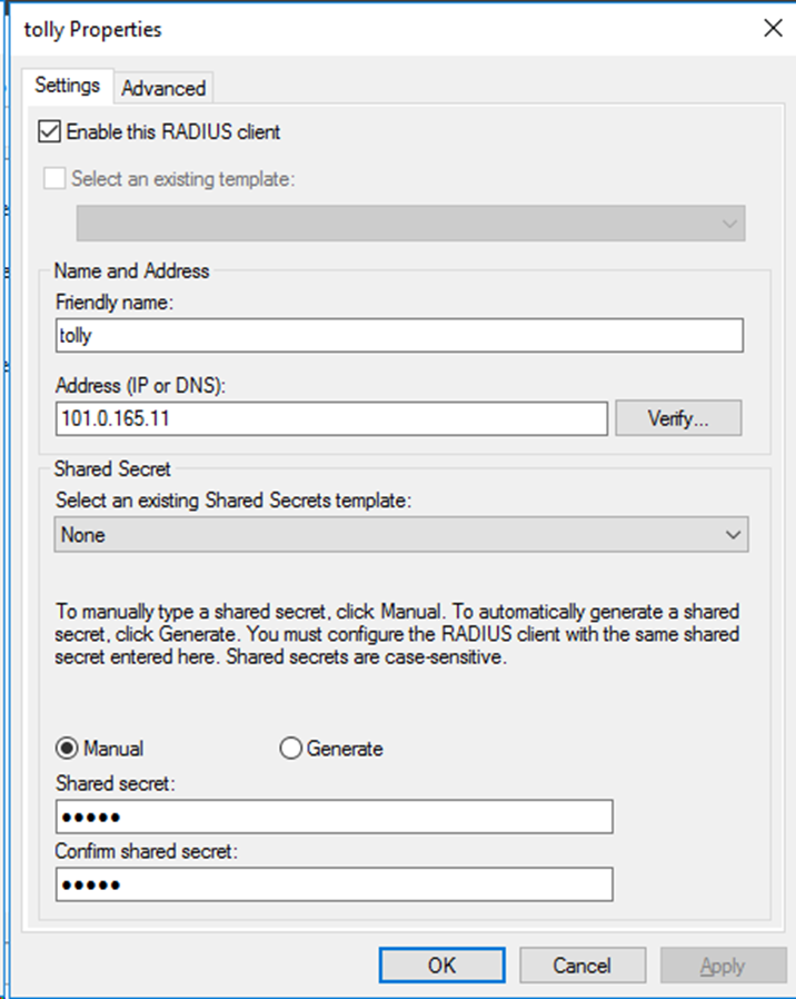
# Click OK.
5. Add a user:
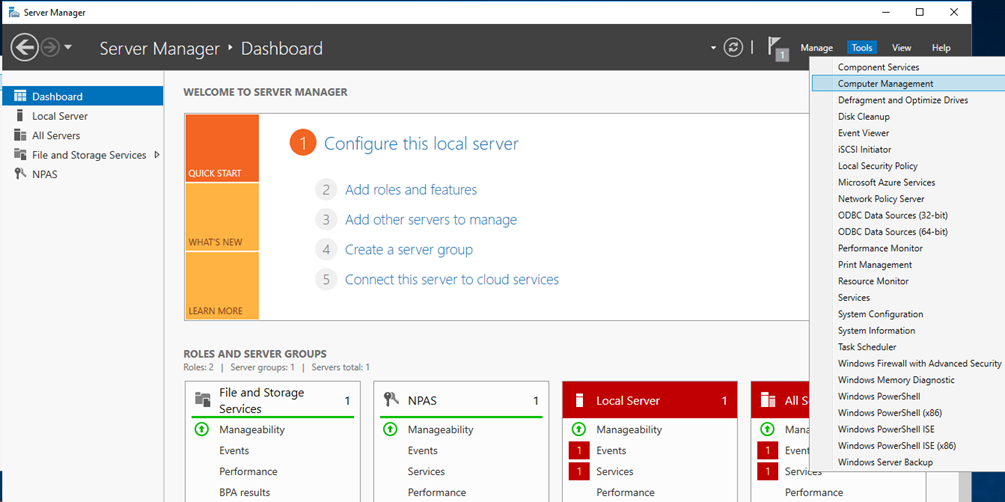
# On the Server Manager Dashboard, select Tools > Computer Management.
Figure 13 Opening the computer management configuration window
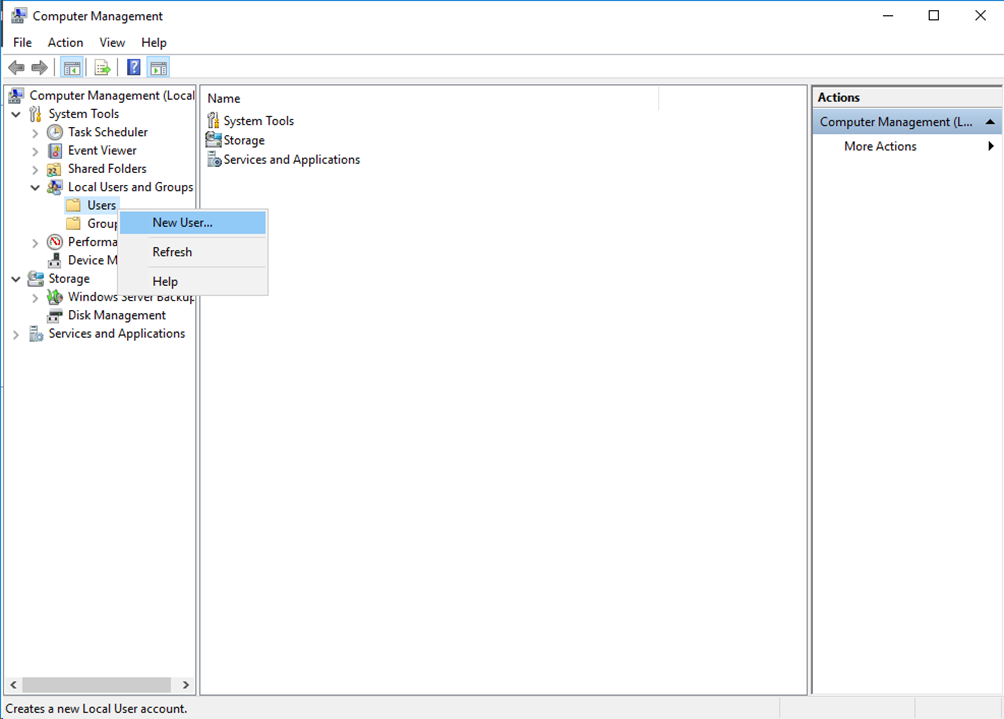
# In the left navigation pane, select Local Users and Groups > Users. Right-click Users and then select New User… to create a new user.
Figure 14 Adding a new user
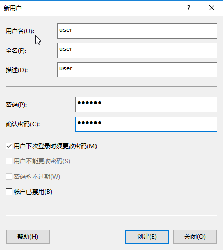
# Create a user. Make sure the username and password of the user are the same as those of the shared account configured for MAC authentication users on the switch.
In this example, the username and password are user and 123456, respectively.
Figure 15 Configuring the new user
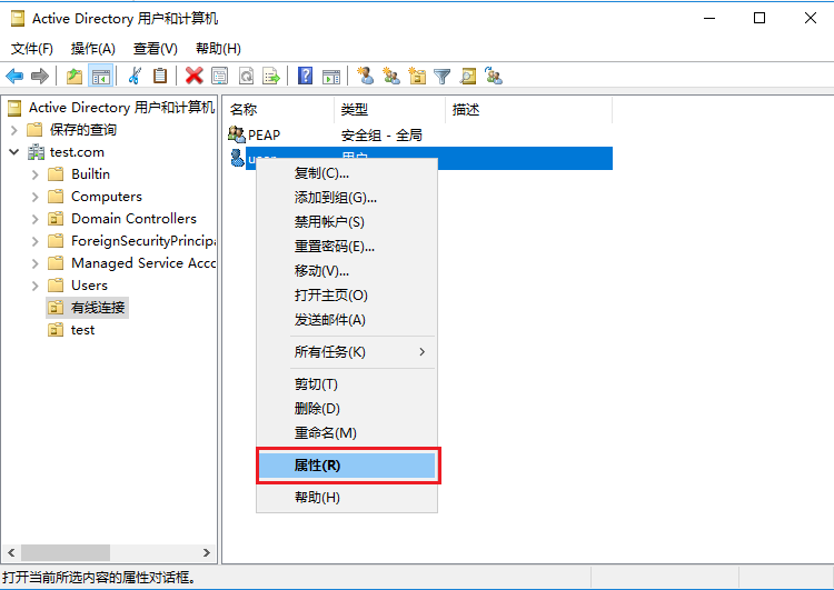
# In the user list, select and right-click user, and then select Properties. On the window that opens, click the Dial-in tab, select Allow access in the Network Access Permission area, and then click OK.
Figure 16 Configuring the network access permission for the user

6. Add a group:
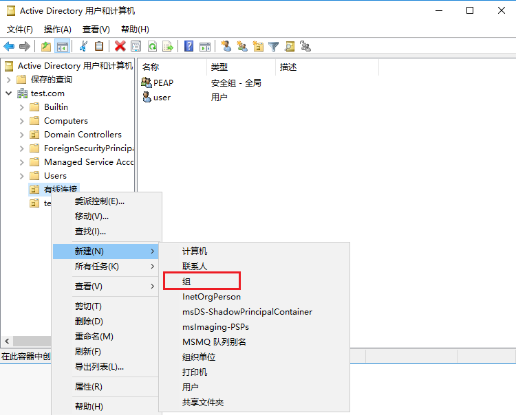
# In the left navigation pane, select Local Users and Groups > Groups. Right-click Groups and then select New Group… to create a new group.
Figure 17 Creating a new group

# On the window that opens, enter the group name, add members to the group, and then click Create.
In this example, the group name is group1 and member user is added to the group.
Figure 18 Creating a group
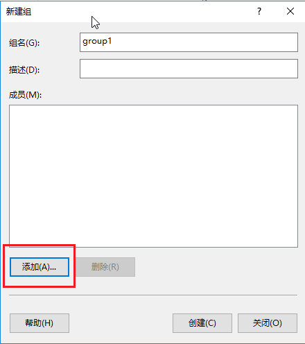
Figure 19 Adding members to the group
7. Add a policy:
# On the Server Manager Dashboard, select Tools > Network Policy Server.
Figure 20 Opening the network policy server configuration window
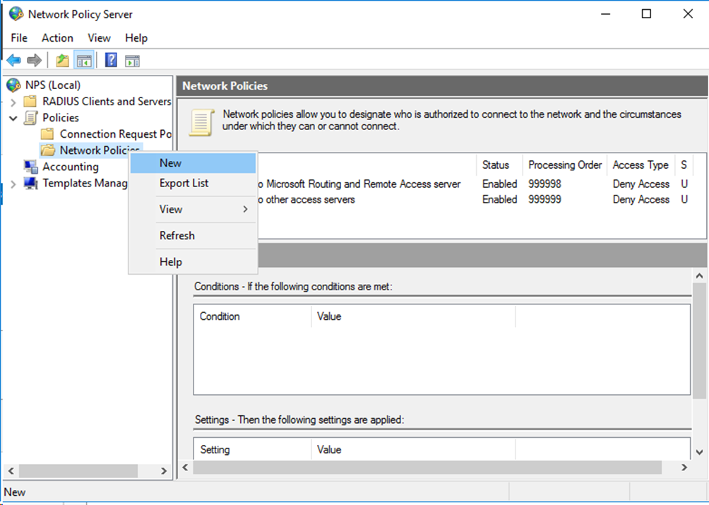
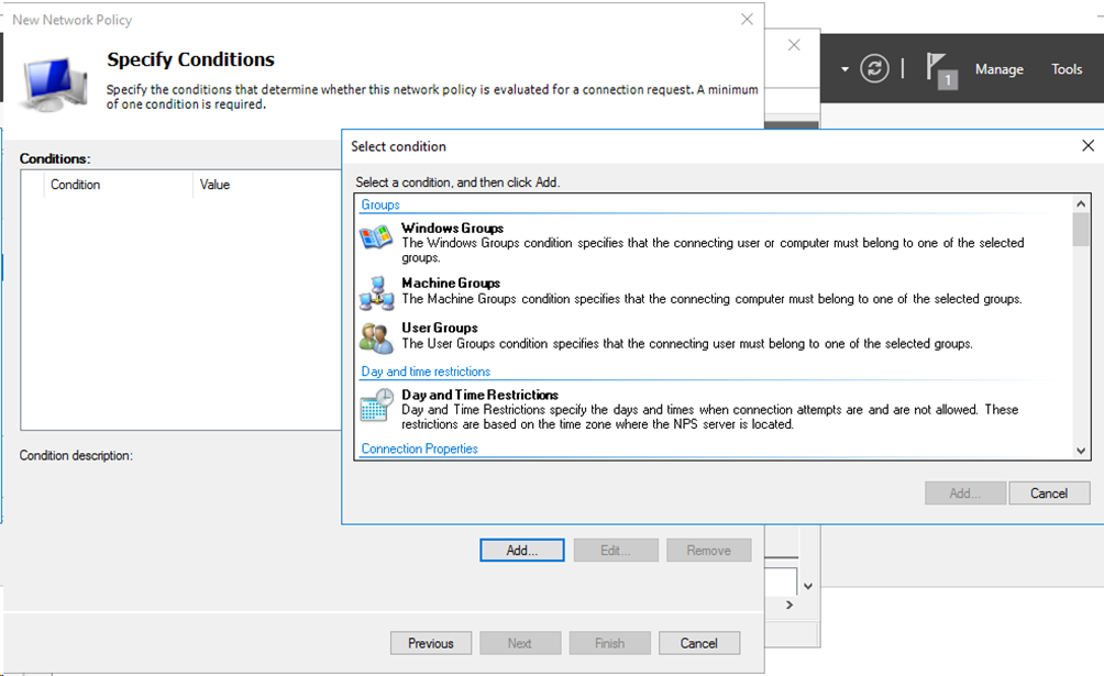
# In the left navigation pane, select Policies > Network Policies. Right-click Network Policies and then select New to create a new network policy.
Figure 21 Creating a new network policy
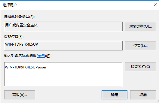
# Click Add… to add a user group for the network policy. On the Window that opens, select User Groups and then click Add….
Figure 22 Adding a user group
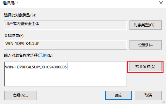
# On the User Groups window, enter the group name in the Enter the object name to select (examples) filed, click Check Names, and then click OK when the associated full group name appears.
In this example, the group name is group1 and the associated full group name is WIN-1DP9IK4L5UP\group1.
Figure 23 Configuring the group

# Specify the access permission as Access granted, and then click Next.
Figure 24 Specifying the access permission

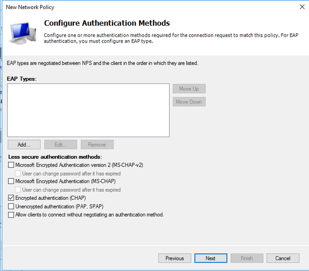
# Specify the authentication method as Encrypted authentication (CHAP), and then click Next to complete the configuration.
Figure 25 Specifying the authentication method
Verifying the configuration
1. On the client, ping the NPS server to verify that you can pass MAC authentication and come online. (Details not shown.)
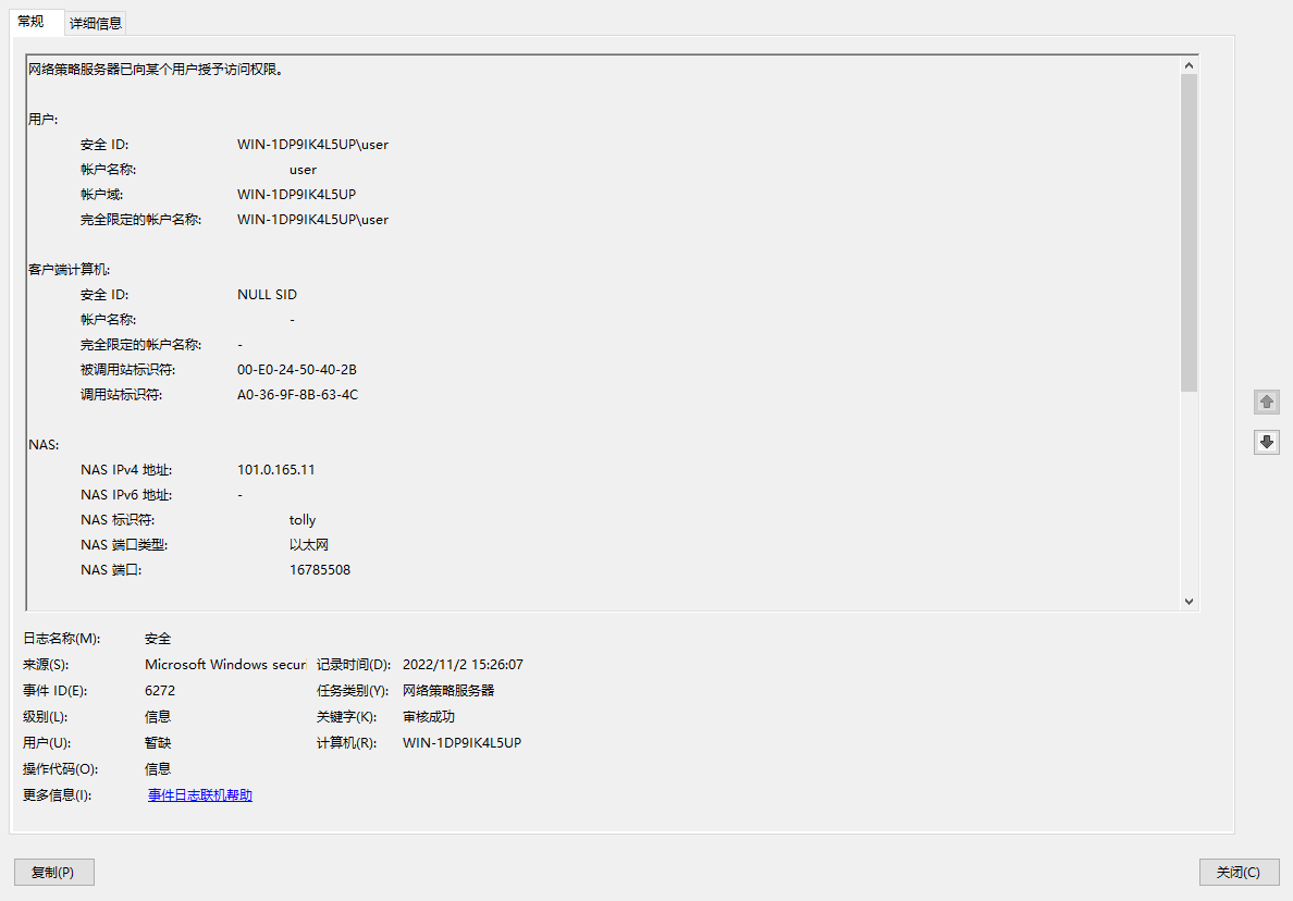
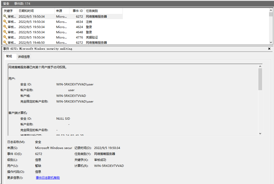
2. On the NPS server, view information about the online user.
Figure 26 Viewing user online information
3. On the switch, use the display mac-authentication connection command to display information about online MAC authentication users.
<Switch> display mac-authentication connection
Total connections: 1
Slot ID: 1
User MAC address: a036-9f8b-634c
Access interface: Ten-GigabitEthernet1/0/2
Username: user
User access state: Successful
Authentication domain: mac-auth
IPv4 address: 101.0.165.12
IPv4 address source: User packet
Initial VLAN: 165
Authorization untagged VLAN: N/A
Authorization tagged VLAN: N/A
Authorization VSI: N/A
Authorization microsegment ID: N/A
Authorization ACL number/name: N/A
Authorization dynamic ACL name: N/A
Authorization user profile: N/A
Authorization CAR: N/A
Authorization URL: N/A
Authorization IPv6 URL: N/A
Authorization temporary redirect: Disabled
Start accounting: Successful
Real-time accounting-update failures: 0
Termination action: Default
Session timeout period: N/A
Offline detection: 300 sec (command-configured)
Online from: 2013/01/08 02:47:40
Online duration: 0h 26m 8s
Port-down keep online: Disabled (offline)
The output shows that the user using the shared account user has passed MAC authentication and come online.
Configuration files
#
mac-authentication
mac-authentication domain mac-auth
mac-authentication user-name-format fixed account user password cipher $c$3$2HmbYwuGcvFCwTALdWqK5AzOvn2w5SY=
mac-authentication authentication-method chap
#
domain mac-auth
authentication lan-access radius-scheme radius1
authorization lan-access radius-scheme radius1
accounting lan-access radius-scheme radius1
#
radius scheme radius1
primary authentication 101.0.144.123
primary accounting 101.0.144.123
key authentication cipher $c$3$9jjl0lp5VA/WXEw065ZIT7j4AIN88XTF
key accounting cipher $c$3$fk1zm9nf2IFMdk+I7hGsyBcsAwqLobi7
user-name-format without-domain
#
interface Ten-GigabitEthernet1/0/2
port link-mode bridge
port access vlan 165
mac-authentication
#
Example: Configuring MAC authentication with MAC-based user accounts
|
|
IMPORTANT: In MAC authentication with MAC-based user accounts, the switch uses the source MAC address in the packet from a user as both the username and password of that user for MAC authentication. |
Configuring the switch
Configure the switch as described in "Example: Configuring MAC authentication with a shared user account" except that you must replace the mac-authentication user-name-format fixed account command with the undo mac-authentication user-name-format command to restore the default user account policy.
[Switch] undo mac-authentication user-name-format
Configuring the Windows Server 2016 NPS server
Configure the NPS server as described in "Example: Configuring MAC authentication with a shared user account," except that you must set the username and password to the MAC address of the MAC authentication user when adding the user to the server.
# On the Server Manager Dashboard, select Tools > Computer Management > Local Users and Groups. Then add a new user and configure the group as follows:
Figure 27 Adding a new user

Figure 28 Configuring the new user

Figure 29 Creating a group
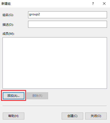
Figure 30 Adding members to the group
Verifying the configuration
1. On the client, ping the NPS server to verify that you can pass MAC authentication and come online. (Details not shown.)
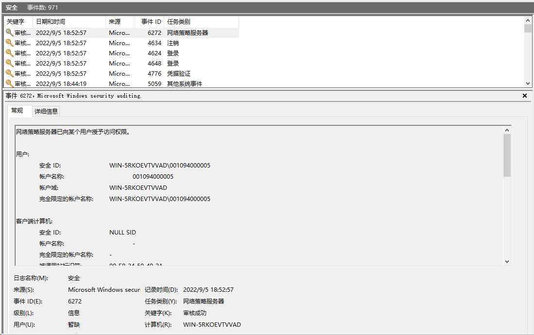
2. On the NPS server, view information about the online user.
Figure 31 Viewing user online information
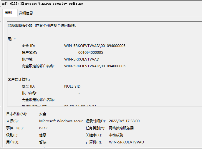
3. On the switch, use the display mac-authentication connection command to display information about online MAC authentication users.
[Switch] display mac-authentication connection
Total connections: 1
Slot ID: 1
User MAC address: 0010-9400-0005
Access interface: Ten-GigabitEthernet1/0/2
Username: 001094000005
User access state: Successful
Authentication domain: mac-auth
IPv4 address: 101.0.165.12
IPv4 address source: User packet
Initial VLAN: 165
Authorization untagged VLAN: N/A
Authorization tagged VLAN: N/A
Authorization VSI: N/A
Authorization microsegment ID: N/A
Authorization ACL number/name: N/A
Authorization dynamic ACL name: N/A
Authorization user profile: N/A
Authorization CAR: N/A
Authorization URL: N/A
Authorization IPv6 URL: N/A
Authorization temporary redirect: Disabled
Start accounting: Successful
Real-time accounting-update failures: 0
Termination action: Default
Session timeout period: N/A
Offline detection: 300 sec (command-configured)
Online from: 2013/01/08 05:10:17
Online duration: 0h 0m 16s
Port-down keep online: Disabled (offline)
The output shows that the user has passed MAC authentication and come online.
Configuration files
#
mac-authentication
mac-authentication domain mac-auth
mac-authentication user-name-format mac-address without-hyphen uppercase
mac-authentication authentication-method chap
#
domain mac-auth
authentication lan-access radius-scheme radius1
authorization lan-access radius-scheme radius1
accounting lan-access radius-scheme radius1
#
radius scheme radius1
primary authentication 101.0.144.123
primary accounting 101.0.144.123
key authentication cipher $c$3$9jjl0lp5VA/WXEw065ZIT7j4AIN88XTF
key accounting cipher $c$3$fk1zm9nf2IFMdk+I7hGsyBcsAwqLobi7
user-name-format without-domain
#
interface Ten-GigabitEthernet1/0/2
port link-mode bridge
port access vlan 165
mac-authentication
#
Examples: Configuring 802.1X authentication
Network configuration
As shown in Figure 32, configure the switch to work in conjunction with the Windows Server 2016 NPS server to perform 802.1X authentication for the client. The client must pass 802.1X authentication to access network resources.
Configure the switch as follows:
· Use the NPS server as the RADIUS server to perform 802.1X authentication for the client.
· Use PAP, CHAP, or certificate authentication (EAP-PEAP, for example) for 802.1X authentication.

Software versions used
This configuration example was created and verified on the following hardware and software versions:
|
Hardware |
Software version |
|
S5560X-54C-PWR-EI switch |
Version 7.1.070 |
|
Authentication server |
Windows Server 2016 NPS |
Example: Configuring 802.1X CHAP authentication
Prerequisites
This example provides only the configuration for authentication. Make sure that the client, switch, and server have network connectivity to communicate with one another.
Configuring the switch
# Create RADIUS scheme radius1, specify the NPS server at 101.0.144.123 for user authentication and accounting, set the shared key to admin in plaintext form, and exclude domain names from the usernames sent to the RADIUS server.
<Switch> system-view
[Switch] radius scheme radius1
[Switch-radius-radius1] primary authentication 101.0.144.123
[Switch-radius-radius1] primary accounting 101.0.144.123
[Switch-radius-radius1] key authentication simple admin
[Switch-radius-radius1] key accounting simple admin
[Switch-radius-radius1] user-name-format without-domain
[Switch-radius-radius1] quit
# Specify an authentication method. This example configures the switch to perform EAP termination and use CHAP to communicate with the RADIUS server.
[Switch] dot1x authentication-method CHAP
# Create ISP domain domain1 and apply the RADIUS scheme to the ISP domain for authentication, authorization, and accounting.
[Switch] domain domain1
[Switch-isp-domain1] authentication default radius-scheme radius1
[Switch-isp-domain1] authorization lan-access radius-scheme radius1
[Switch-isp-domain1] accounting lan-access radius-scheme radius1
[Switch-isp-domain1] quit
# Create VLAN 165 and VLAN-interface 165, and assign an IP address to the VLAN interface.
[Switch] vlan 165
[Switch-vlan165] quit
[Switch] interface Vlan-interface 165
[Switch-Vlan-interface165] ip address 101.0.165.11 255.255.255.0
[Switch-Vlan-interface165] quit
# Assign Ten-GigabitEthernet 1/0/49 to VLAN 165.
[Switch]interface Ten-GigabitEthernet 1/0/49
[Switch-Ten-GigabitEthernet1/0/49] port access vlan 165
# Enable 802.1X on Ten-GigabitEthernet 1/0/49 and specify ISP domain domain1 as the mandatory domain.
[Switch-Ten-GigabitEthernet1/0/49] dot1x
[Switch-Ten-GigabitEthernet1/0/49] dot1x mandatory-domain domain1
# Enable port-based access control on Ten-GigabitEthernet 1/0/49.
[Switch-Ten-GigabitEthernet1/0/49] dot1x port-method portbased
[Switch-Ten-GigabitEthernet1/0/49] quit
# Assign Ten-GigabitEthernet 1/0/2 to VLAN 165.
[Switch] interface Ten-GigabitEthernet 1/0/2
[Switch-Ten-GigabitEthernet1/0/2] port access vlan 165
[Switch-Ten-GigabitEthernet1/0/2] quit
# Specify ISP domain domain1 as the default ISP domain.
[Switch] domain default enable domain1
# Enable 802.1X globally.
[Switch] dot1x
Configuring the Windows Server 2016 NPS server
Configure the NPS server as described in "Example: Configuring MAC authentication with a shared user account."
Verifying the configuration
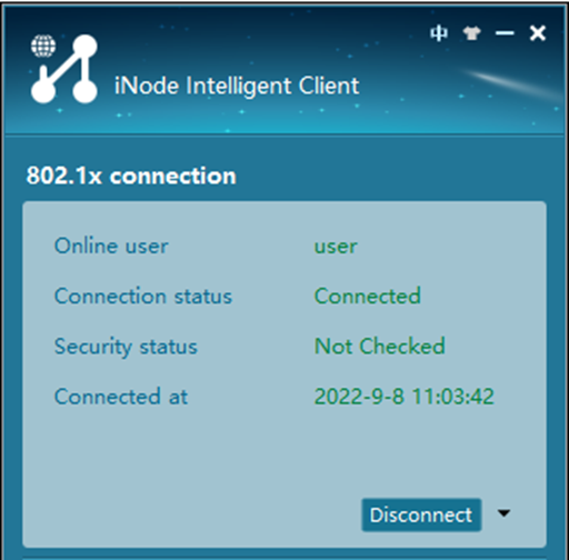
1. Use the iNode client to verify that you can pass 802.1X authentication to come online after you enter the username and password.
Figure 33 Accessing through the iNode client
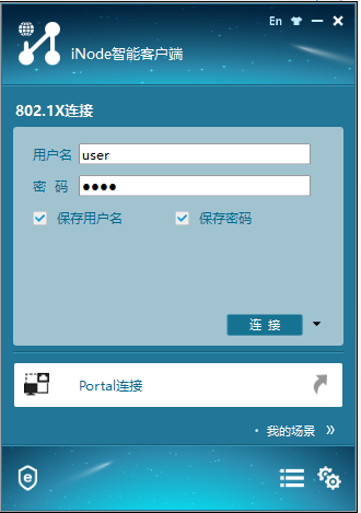
Figure 34 Successful 802.1X connection
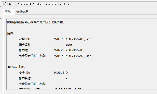
2. On the NPS server, view information about the online user.
Figure 35 Viewing user access information
3. On the switch, use the display dot1x connection command to display information about online 802.1X authentication users.
[Switch] display dot1x connection
Total connections: 1
Slot ID: 1
User MAC address: a036-9f8b-634c
Access interface: Ten-GigabitEthernet1/0/2
Username: user
User access state: Successful
Authentication domain: domain1
EAP packet identifier: 2
Authentication method: CHAP
AAA authentication method: RADIUS
Initial VLAN: 165
Authorization untagged VLAN: N/A
Authorization tagged VLAN list: N/A
Authorization VSI: N/A
Authorization microsegment ID: N/A
Authorization ACL number/name: N/A
Authorization dynamic ACL name: N/A
Authorization user profile: N/A
Authorization CAR: N/A
Authorization URL: N/A
Authorization IPv6 URL: N/A
Authorization temporary redirect: Disabled
Start accounting: Successful
Real-time accounting-update failures: 0
Termination action: Default
Session timeout period: N/A
Online from: 2013/01/03 08:22:24
Online duration: 0h 0m 35s
The output shows that the user has passed 802.1X CHAP authentication and come online.
Configuration files
#
dot1x
#
interface Ten-GigabitEthernet1/0/2
port link-mode bridge
port link-type hybrid
port hybrid vlan 1 100 165 untagged
port hybrid pvid vlan 165
undo dot1x handshake
dot1x mandatory-domain domain1
undo dot1x multicast-trigger
dot1x port-method portbased
#
domain domain1
authentication lan-access radius-scheme radius1
authorization lan-access radius-scheme radius1
accounting lan-access radius-scheme radius1
#
radius scheme radius1
primary authentication 101.0.144.123
primary accounting 101.0.144.123
key authentication cipher $c$3$9jjl0lp5VA/WXEw065ZIT7j4AIN88XTF
key accounting cipher $c$3$fk1zm9nf2IFMdk+I7hGsyBcsAwqLobi7
user-name-format without-domain
#
Example: Configuring 802.1X PAP authentication
Configuring the switch
Configure the switch as described in "Configuring the switch," except that you must set the authentication method to PAP as follows:
[Switch] dot1x authentication-method PAP
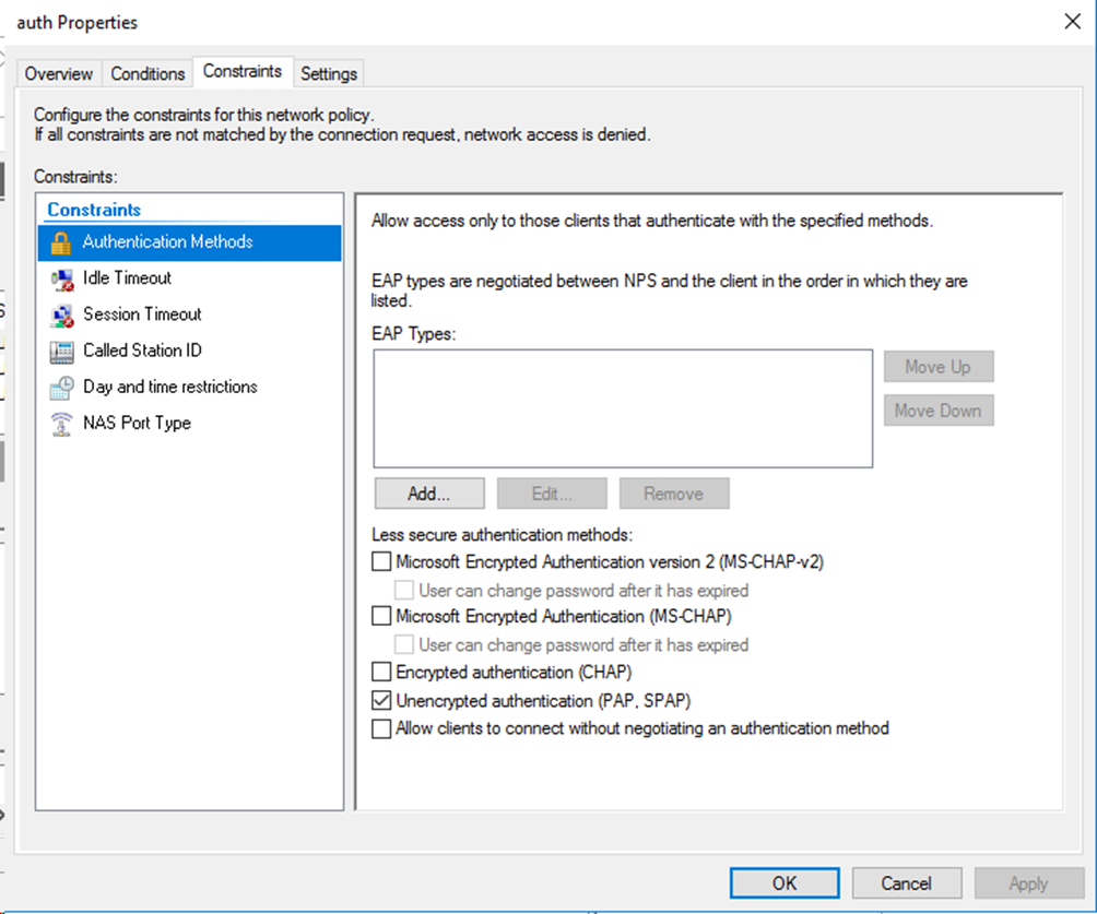
Configuring the Windows Server 2016 NPS server
Configure the NPS server as described in "Configuring the Windows Server 2016 NPS server," except that you must specify the authentication method as Unencrypted authentication (PAP, SPAP) for the network policy.
Figure 36 Specifying the authentication method
Verifying the configuration
1. Use the iNode client to verify that you can pass 802.1X authentication to come online after you enter the username and password. (Details not shown.)
2. On the NPS server, view information about the online user.
Figure 37 Viewing user access information

3. On the switch, use the display dot1x connection command to display information about online 802.1X authentication users.
[Switch] display dot1x connection
Total connections: 1
Slot ID: 1
User MAC address: a036-9f8b-634c
Access interface: Ten-GigabitEthernet1/0/2
Username: user
User access state: Successful
Authentication domain: domain1
EAP packet identifier: 2
Authentication method: PAP
AAA authentication method: RADIUS
Initial VLAN: 165
Authorization untagged VLAN: N/A
Authorization tagged VLAN list: N/A
Authorization VSI: N/A
Authorization microsegment ID: N/A
Authorization ACL number/name: N/A
Authorization dynamic ACL name: N/A
Authorization user profile: N/A
Authorization CAR: N/A
Authorization URL: N/A
Authorization IPv6 URL: N/A
Authorization temporary redirect: Disabled
Start accounting: Successful
Real-time accounting-update failures: 0
Termination action: Default
Session timeout period: N/A
Online from: 2013/01/03 08:25:51
Online duration: 0h 0m 8s
The output shows that the user has passed 802.1X PAP authentication and come online.
Configuration files
#
dot1x
dot1x authentication-method pap
#
interface Ten-GigabitEthernet1/0/2
port link-mode bridge
port link-type hybrid
port hybrid vlan 1 100 165 untagged
port hybrid pvid vlan 165
undo dot1x handshake
dot1x mandatory-domain domain1
undo dot1x multicast-trigger
dot1x port-method portbased
#
domain domain1
authentication lan-access radius-scheme radius1
authorization lan-access radius-scheme radius1
accounting lan-access radius-scheme radius1
#
radius scheme radius1
primary authentication 101.0.144.123
primary accounting 101.0.144.123
key authentication cipher $c$3$9jjl0lp5VA/WXEw065ZIT7j4AIN88XTF
key accounting cipher $c$3$fk1zm9nf2IFMdk+I7hGsyBcsAwqLobi7
user-name-format without-domain
#
Example: Configuring 802.1X EAP-PEAP authentication
Configuring the switch
Configure the switch as described in "Configuring the switch," except that you must set the authentication method to EAP as follows:
[Switch] dot1x authentication-method EAP
Configuring the Windows Server 2016 NPS server
Configure the NPS server as described in "Configuring the Windows Server 2016 NPS server," except that you must use the following settings in this example:
1. Configure the Active Directory domain controller for user management:
a. Install Active Directory domain-related services.
On the Add Roles and Features Wizard, click Server Roles, select Active Directory Domain Services and Active Directory Lightweight Directory Services, and then continuously click Next. Close the window when the installation is completed.
Figure 38 Specifying the server roles

b. Configure the Active Directory domain controller:
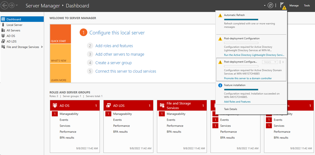
# On the Server Manager Dashboard, click Manage > Promote this server to a domain controller.
Figure 39 Promoting the server to a domain controller
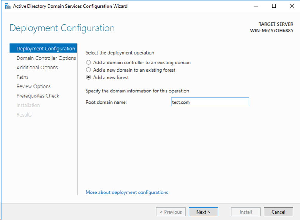
# On the Active Directory Domain Services Configuration Wizard that opens, click Deployment Configuration in the left navigation pane. Specify Add a new forest as the deployment operation, and enter the root domain name. In this example, test.com is used.
Figure 40 Specifying the authentication method
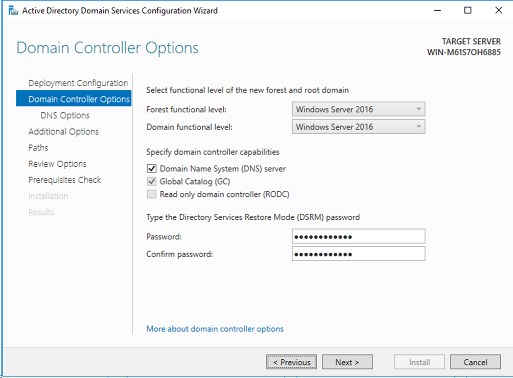
# Click Domain Controller Options in the left navigation pane, and enter the Directory Services Restore Mode (DSRM) password. You do not need to configure the settings on the DNS Options pane.
Figure 41 Configuring the domain controller options
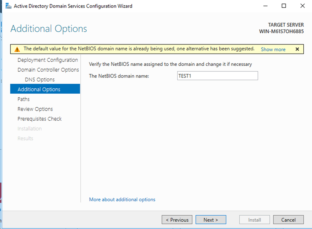
# Click Additional Options in the left navigation pane, and enter the NetBIOS domain name. You must record this domain name. After the server is promoted to a domain controller, you need to log in to this domain.
Figure 42 Configuring the domain controller options
# Continuously click Next until the All prerequisite checks passed successfully. Click 'Install' to begin installation message appears on the Prerequisites Check pane. Then click Install. The server will automatically reboot after the installation is completed.
Figure 43 Configuring the prerequisites check

c. Create an Active Directory user:
# On the Server Manager Dashboard, click Tools > Active Directory Users and Computers.
Figure 44 Opening the Active Directory Users and Computers configuration window

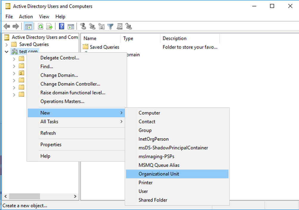
# On the window that opens, select and right-click the configured root domain name, and then select New > Organizational Unit to create an organizational unit.
Figure 45 Creating an organizational unit
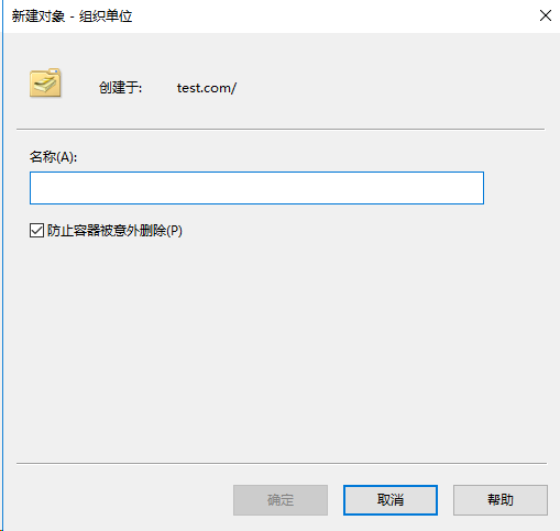
# On the window that opens, enter the name of the organizational unit, and then click OK.
Figure 46 Configuring the organizational unit
# Select and right-click the configured organizational unit, and then select New > Group.
Figure 47 Creating a group
# On the window that opens, enter the group name, specify the group scope and the group type, and then click OK.
Figure 48 Configuring the group

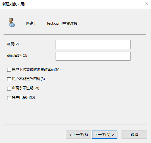
# Select and right-click the configured organizational unit, and then select New > User. On the window that opens, specify the name, user login name, and other parameters for the user.
Figure 49 Creating a user
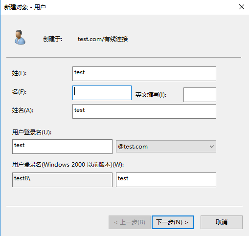
# Click Next. Enter the password and re-enter the password for confirmation. You must record the password for subsequent login.
Figure 50 Configuring user password
# Select and right-click the created user in the user list, and then select Properties.
Figure 51 Selecting the created user
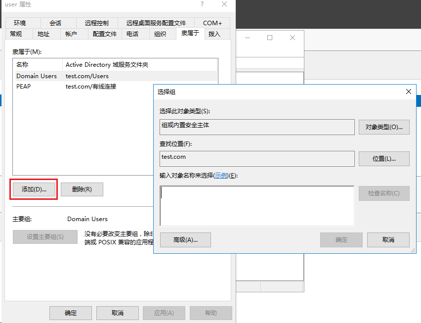
# On the window that opens, click the Member Of tab, and then click Add…. On the Select Groups window that opens, select the configured group, and then click OK.
Figure 52 Adding a group for the user
2. Install the RADIUS server:
a. Install the role services for Active Directory Certificate Services:
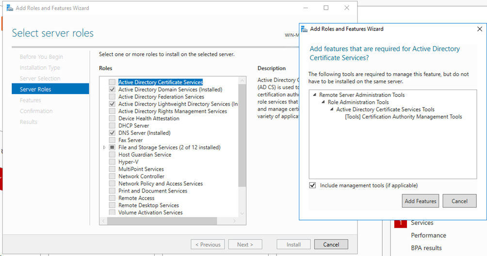
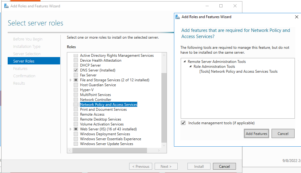
# On the Add Roles and Features Wizard, click Server Roles, select Active Directory Certificate Services, and then click Add Features on the window that opens.
Figure 53 Configuring Active Directory Certificate Services
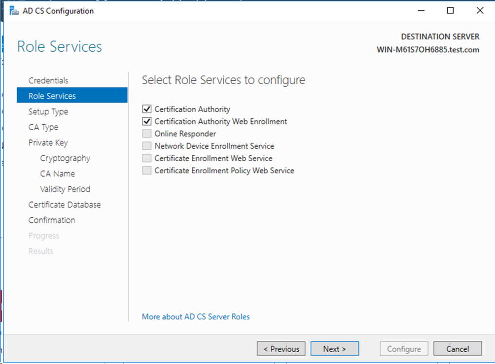
# On the Add Roles and Features Wizard, click AD CS > Role Services, select Certification Authority and Certification Authority Web Enrollment. Then continuously click Next.
Figure 54 Configuring the role services

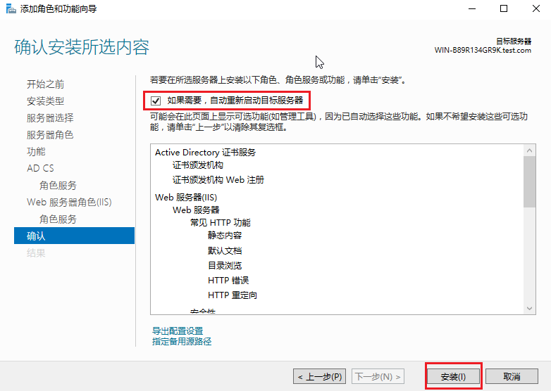
# On the Confirmation pane, select Restart the destination server automatically if required, and then click Install to complete the installation.
Figure 55 Confirming installation selections
b. Configure Active Directory Certificate Services:
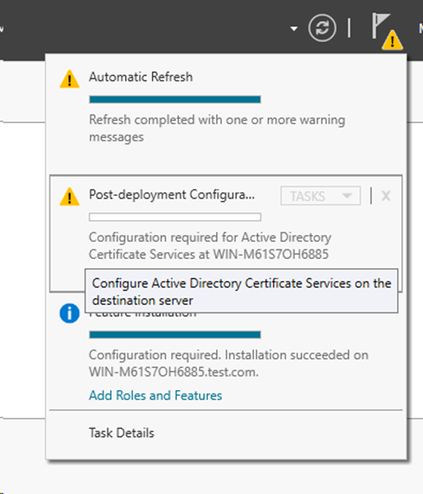
# On the Server Manager Dashboard, click Manage > Configure Active Directory Certificate Services on the destination server.
Figure 56 Opening the Active Directory Certificate Services configuration window
# On the Add CS Configuration window, click Role Services in the left navigation pane, and then select Certification Authority and Certification Authority Web Enrollment.
Figure 57 Configuring the role services
# Continuously click Next until Configuration succeeded appears for both services on the Results pane.
Figure 58 Successful configuration

c. Request certificates:
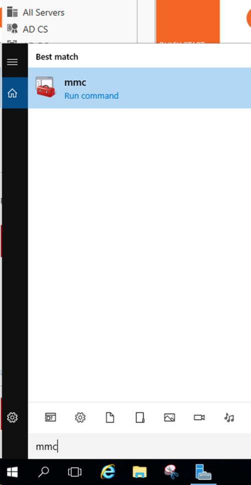
# Type mmc in the search box and press Enter to open the MMC console.
Figure 59 Opening the MMC console
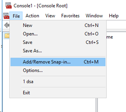
# Click File > Add/Remove Snap-in….
Figure 60 Adding/Removing snap-ins
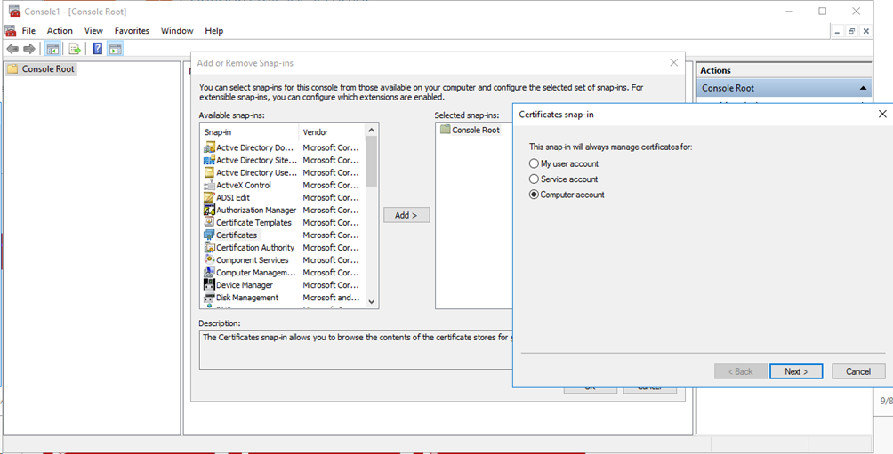
# Add the Certificates and Certificate Templates snap-ins. On the window that opens, select Computer account and click Next.
Figure 61 Adding snap-ins
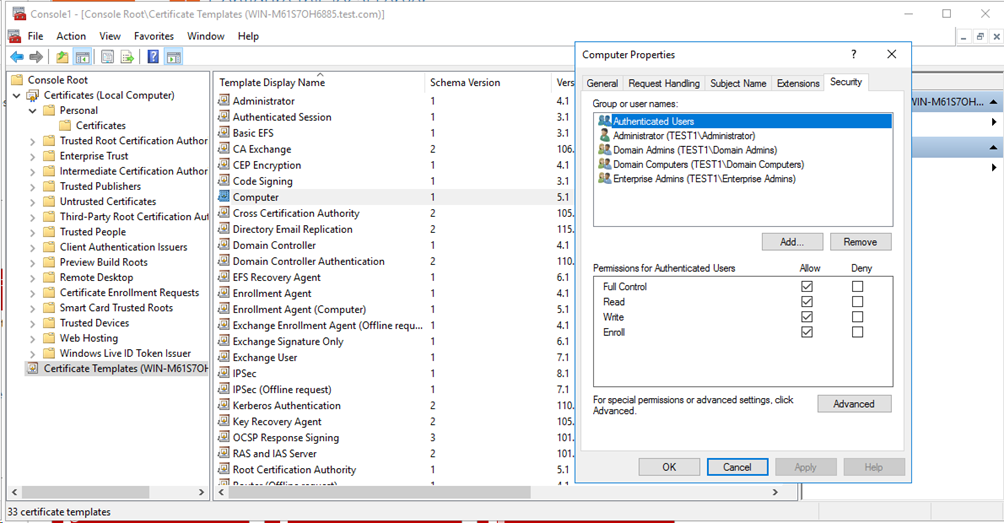
# Select Certificate Templates (Computer Name) > Computer. Right-click Computer and then select Properties. On the window that opens, select the Security tab, add the authenticated users logged in to the computer, and select Allow for the Full Control filed.
Figure 62 Configuring the certificate templates
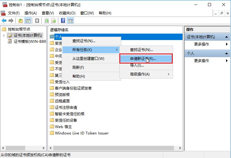
# Select Certificates (Local Computer) in the left navigation pane, select and right-click Personal, and then select All Tasks > Request New Certificate….
Figure 63 Requesting new certificates
# On the window that opens, select the Computer enrollment policy, and then click Enroll to complete certificate enrollment.
Figure
64 Selecting the enrollment policy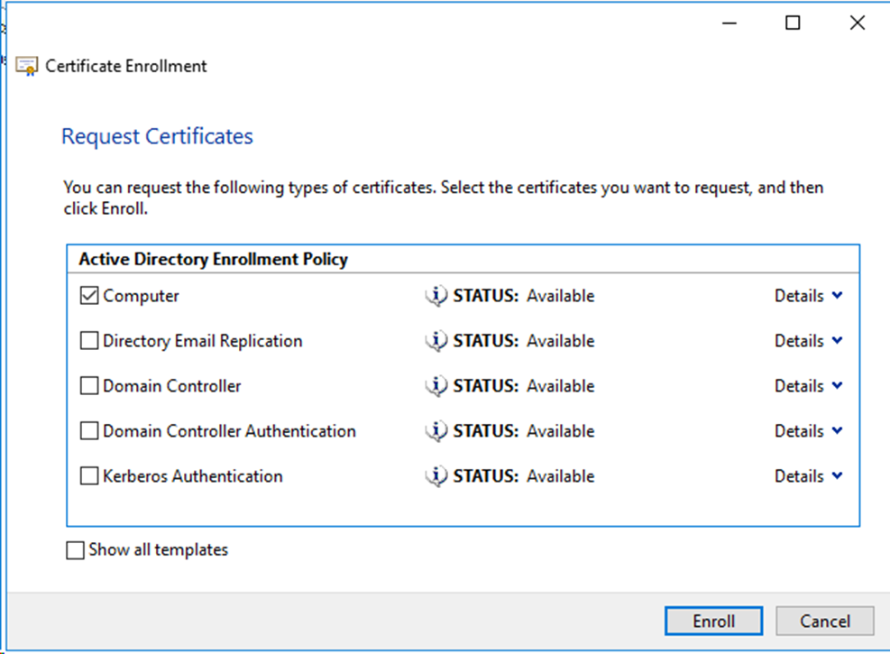
d. Install the NPS server.
# On the Server Manager Dashboard, select Manage > Add Roles and Features. On the window that opens, select Server Roles in the left navigation pane, and select Network Policy and Access Services. Continuously click Next until the Confirmation interface appears. Select Restart the destination server automatically if required, and then click Install to complete the installation.
Figure 65 Configuring the server roles
e. Configure the NPS server:
# On the Server Manager NPAS, select and right-click the configured server, and then select Network Policy Server.
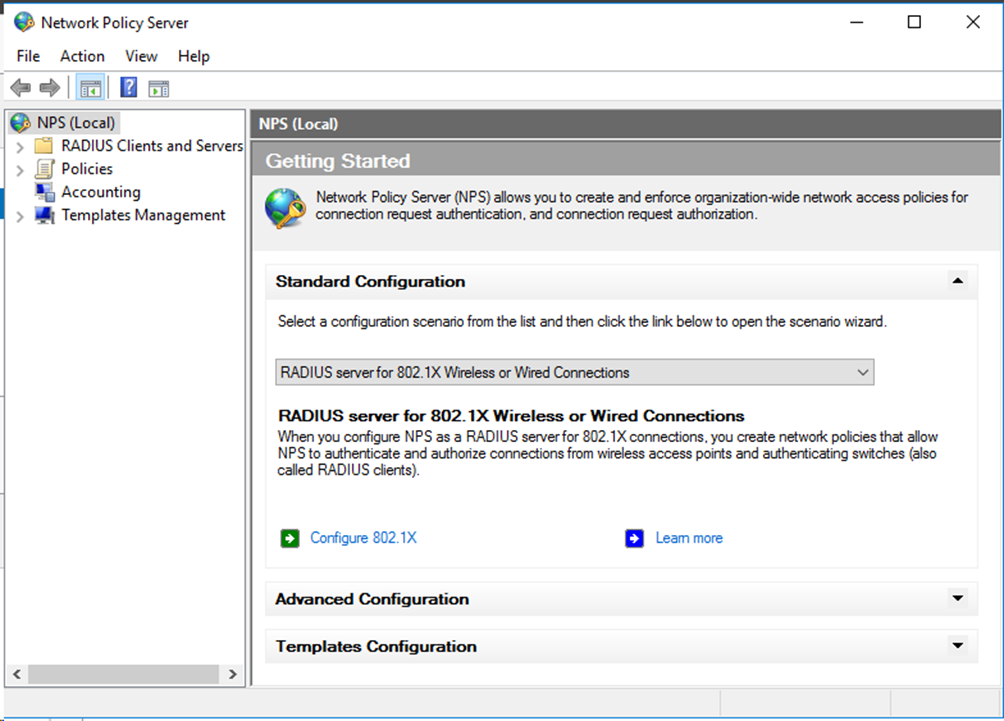
Figure 66 Opening the network policy server configuration window

# On the window that opens, specify the standard configuration as RADIUS server for 802.1X Wireless or Wired Connections, and then click Configure 802.1X.
Figure 67 Creating 802.1X wired connections
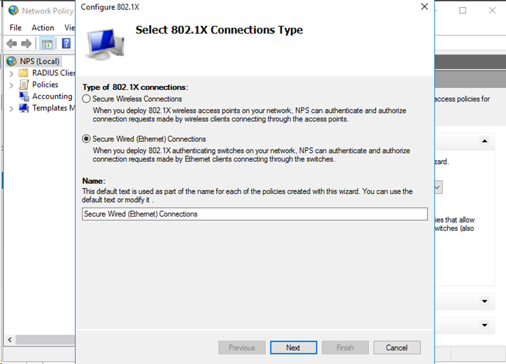
# On the Configure 802.1X window that opens, select Secure Wired (Ethernet) Connections, and then enter the connection name.
Figure 68 Configuring the connection name
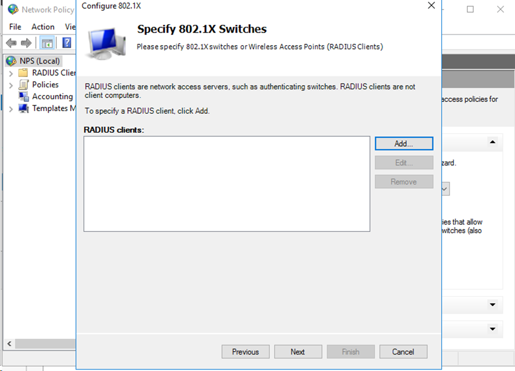
# Click Add….
Figure 69 Specifying the RADIUS client
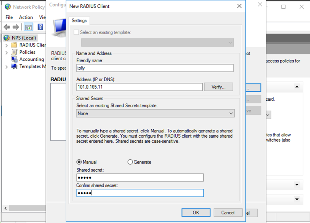
# On the window that opens, specify the friendly name, address, and shared secret for the RADIUS client, and then click OK.
Figure 70 Configuring the RADIUS client
# Click Next. On the window that opens, specify the authentication method as Microsoft: Protected EAP (PEAP).
Figure 71 Configuring the authentication method

# Click Next and then click Add…. On the window that opens, select the configured group and then click OK. Continuously click Next until the configuration is completed.
Figure 72 Specifying the user group

f. Register the server in Active Directory.
# On the Network Policy Server window, select and right-click NPS(Local), and then select Register server in Active Directory to complete the registry.
Figure 73 Registering the server in Active Directory

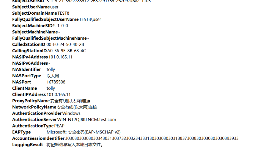
Verifying the configuration
1. Verify that you can log in to the server from the client by using a wired NIC. (Details not shown.)
2. On the NPS server, view information about the online user.
Figure 74 Viewing user online information
3. On the switch, use the display dot1x connection command to display information about online 802.1X authentication users.
<Switch> display dot1x connection
Total connections: 1
Slot ID: 1
User MAC address: a036-9f8b-634c
Access interface: Ten-GigabitEthernet1/0/2
Username: user
User access state: Successful
Authentication domain: eap
EAP packet identifier: 11
Authentication method: EAP
AAA authentication method: RADIUS
Initial VLAN: 165
Authorization untagged VLAN: N/A
Authorization tagged VLAN list: N/A
Authorization VSI: N/A
Authorization microsegment ID: N/A
Authorization ACL number/name: N/A
Authorization dynamic ACL name: N/A
Authorization user profile: N/A
Authorization CAR: N/A
Authorization URL: N/A
Authorization IPv6 URL: N/A
Authorization temporary redirect: Disabled
Start accounting: Successful
Real-time accounting-update failures: 0
Termination action: Default
Session timeout period: N/A
Online from: 2013/01/07 20:24:31
Online duration: 0h 0m 14s
The output shows that the user has passed 802.1X EAP-TTLS authentication and come online.
Configuration files
#
dot1x
dot1x authentication-method peap
#
interface Ten-GigabitEthernet1/0/2
port link-mode bridge
port link-type hybrid
port hybrid vlan 1 100 165 untagged
port hybrid pvid vlan 165
undo dot1x handshake
dot1x mandatory-domain domain1
undo dot1x multicast-trigger
dot1x port-method portbased
#
domain domain1
authentication lan-access radius-scheme radius1
authorization lan-access radius-scheme radius1
accounting lan-access radius-scheme radius1
#
radius scheme radius1
primary authentication 101.0.144.123
primary accounting 101.0.144.123
key authentication cipher $c$3$9jjl0lp5VA/WXEw065ZIT7j4AIN88XTF
key accounting cipher $c$3$fk1zm9nf2IFMdk+I7hGsyBcsAwqLobi7
user-name-format without-domain
#
Example: Configuring local portal authentication through the LDAP server
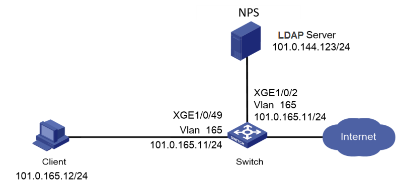
Network configuration
As shown in Figure 75, configure the switch to work in conjunction with the Windows Server 2016 NPS server to perform portal authentication for the client. The client must pass portal authentication to access network resources.
Configure the switch as follows:
· Use the NPS server as the LDAP server and portal authentication server to perform portal authentication for the client.
· Use direct portal authentication.
Software versions used
This configuration example was created and verified on the following hardware and software versions:
|
Hardware |
Software version |
|
S5560X-54C-PWR-EI switch |
Version 7.1.070 |
|
Authentication server |
Windows Server 2016 NPS |
Procedures
Prerequisites
This example provides only the configuration for authentication. Make sure that the client, switch, and server have network connectivity to communicate with one another.
Configuring the switch
# Create an HTTP-based local portal Web service and enter its view. Specify the listening TCP port number as 2331.
<Switch> system-view
[Switch] portal local-web-server http tcp-port 2331
[Switch-portal-local-websvr-http] quit
# Configure the URL for the portal Web server newpt as http://101.0.165.11:2331/portal.
[Switch] portal web-server newpt
[Switch-portal-websvr-newpt] url http://101.0.165.11:2331/portal
[Switch-portal-websvr-newpt] quit
# Create LDAP server ccc, configure the administrator DN, the base DN for user search, the IP address of the LDAP authentication server, and the administrator password.
[Switch] ldap server ccc
[Switch-ldap-server-ccc] login-dn cn=administrator,cn=users,dc=test,dc=com
[Switch-ldap-server-ccc] search-base-dn dc=test,dc=com
[Switch-ldap-server-ccc] ip 101.0.144.124
[Switch-ldap-server-ccc] login-password cipher 123456
[Switch-ldap-server-ccc] quit
# Create LDAP scheme ldap1 and specify the LDAP authentication server as ccc.
[Switch] ldap scheme ldap1
[Switch-ldap-ldap1] authentication-server ccc
[Switch-ldap-ldap1] quit
# Create VLAN 165 and VLAN-interface 165, and assign an IP address to the VLAN interface. Specify portal Web server newpt on VLAN-interface 165.
[Switch] vlan 165
[Switch-vlan165] quit
[Switch] interface Vlan-interface 165
[Switch-Vlan-interface165] ip address 101.0.165.11 255.255.255.0
[Switch-Vlan-interface165] portal apply web-server newpt
[Switch-Vlan-interface165] quit
# Assign Ten-GigabitEthernet 1/0/47 and Ten-GigabitEthernet 1/0/2 to VLAN 165.
[Switch] interface Ten-GigabitEthernet 1/0/47
[Switch-Ten-GigabitEthernet1/0/47] port access vlan 165
[Switch-Ten-GigabitEthernet1/0/47] quit
[Switch] interface Ten-GigabitEthernet 1/0/2
[Switch-Ten-GigabitEthernet1/0/2] port access vlan 165
[Switch-Ten-GigabitEthernet1/0/2] quit
# Create ISP domain domain1, configure the authentication method as LDAP and the authorization and accounting methods as none for portal users in the ISP domain.
[switch] domain domain1
[switch-isp-domain1] authentication portal ldap-scheme ldap1
[switch-isp-domain1] authorization portal none
[switch-isp-domain1] accounting portal none
[switch-isp-domain1] quit
# Specify ISP domain domain1 as the default ISP domain.
[Switch] domain default enable domain1
# Enable direct portal authentication on VLAN-interface 165.
[Switch] interface Vlan-interface 165
[Switch-Vlan-interface165] portal enable method direct
[Switch-Vlan-interface165] quit
|
|
NOTE: A user can use direct portal authentication or cross-subnet portal authentication to come online. To perform cross-subnet portal authentication, replace the portal enable method direct command with the portal enable method layer3 command on the switch. No configuration change is required on the server and client. |
Configuring the Windows Server 2016 NPS server
Configure the NPS server as described in "Configuring the Windows Server 2016 NPS server."
Verifying the configuration
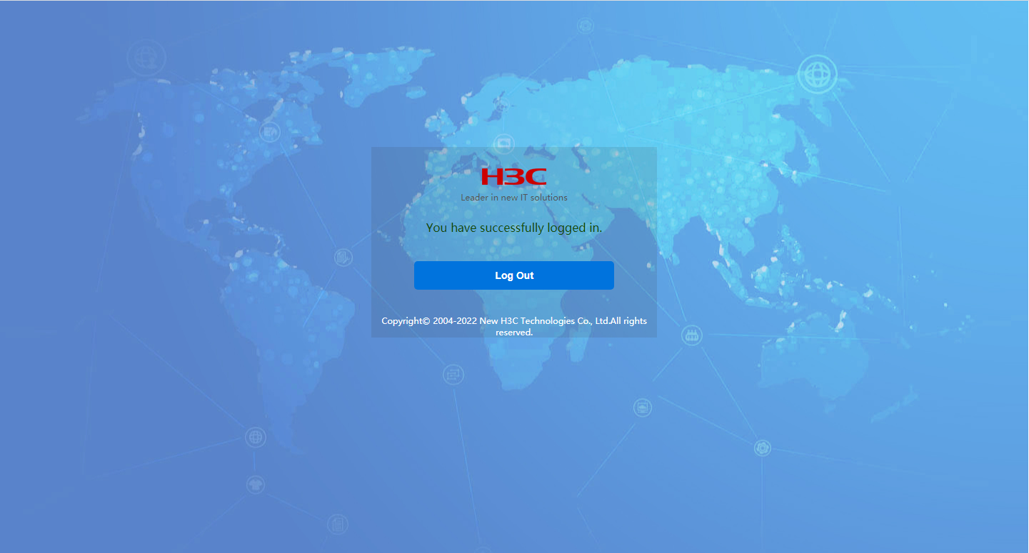
1. On the client, open a Web browser, type the portal authentication IP (101.0.165.11) in the address bar, and press Enter. On the login page that opens, type the username and password of the user account configured on the server, and then click Log In. Verify that you can successfully logged in.
Figure 76 Web login page

Figure 77 Successful login
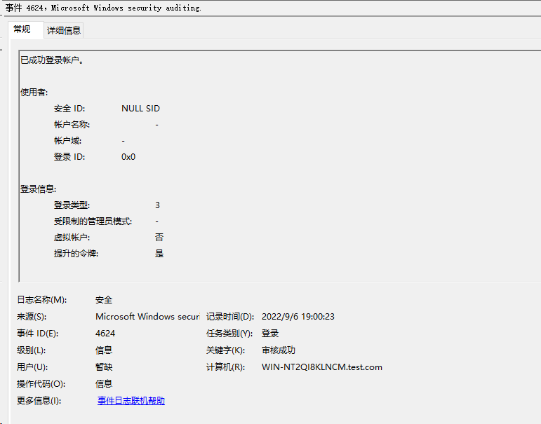
2. On the NPS server, view information about the online user.
Figure 78 Viewing user online information
3. On the switch, use the display portal user command to display information about portal users.
<Switch> display portal user all
Total portal users: 1
Username: user
Portal server:
State: Online
VPN instance: N/A
MAC IP VLAN Interface
a036-9f8b-634c 101.0.165.12 165 Vlan-interface165
Authorization information:
DHCP IP pool: N/A
User profile: N/A
Session group profile: N/A
ACL number: N/A
Inbound CAR: N/A
Outbound CAR: N/A
The output shows that the user has passed portal authentication and come online.
Configuration files
#
interface Vlan-interface165
ip address 101.0.165.11 255.255.255.0
portal enable method direct
portal apply web-server newpt
#
domain ldap
authentication portal ldap-scheme ldap
authorization portal none
accounting portal none
#
ldap scheme ldap
authentication-server ldap
#
ldap server ldap
login-dn cn=administrator,cn=users,dc=test,dc=com
search-base-dn dc=test,dc=com
ip 101.0.144.124
login-password cipher $c$3$MU1UdAnLgSFni5hERPL15CYR7NsHW6RkErhr3bQuNA==
#
portal web-server newpt
url http://101.0.165.11:2331/portal
#
portal local-web-server http
default-logon-page en.zip
tcp-port 2331
#
Examples: Configuring 802.1X or MAC authentication with VLAN assignment
Network configuration
As shown in Figure 79, configure the switch to work in conjunction with the Windows Server 2016 NPS server to perform 802.1X or MAC authentication for the client. The client must pass 802.1X or MAC authentication to access network resources.
Configure the switch as follows:
· Use the NPS server as the RADIUS server to perform 802.1X or MAC authentication for the client.
· Configure the NPS server to assign an authorization VLAN to the client after the client passes 802.1X or MAC authentication. The initial VLAN is 144.

Software versions used
This configuration example was created and verified on the following hardware and software versions:
|
Hardware |
Software version |
|
S5560X-54C-PWR-EI switch |
Version 7.1.070 |
|
Authentication server |
Windows Server 2016 NPS |
Example: Configuring 802.1X or MAC authentication with VLAN ID assignment
Configuring the switch
For MAC authentication users, configure the switch as described in "Configuring the switch."
For 802.1X authentication users, configure the switch as described in "Configuring the switch."
Configuring the Windows Server 2016 NPS server
Configure basic settings:
· Configure the NPS server for MAC authentication users as described in "Configuring the Windows Server 2016 NPS server."
· Configure the NPS server for 802.1X users as described in "Configuring the Windows Server 2016 NPS server."
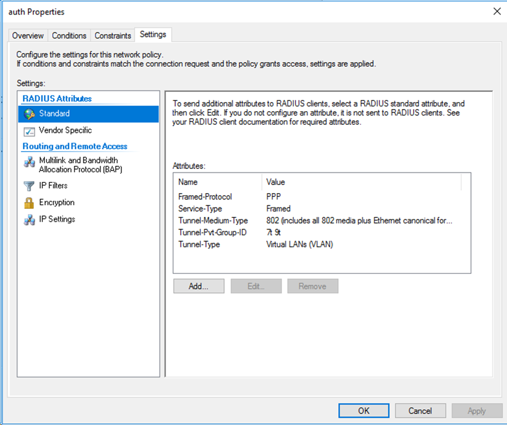
For VLAN assignment, you must edit the RADIUS attributes on the Settings tab for the network policy as follows:
· Add the Tunnel-Medium-Type attribute to specify the tunnel medium type, and set the value for the attribute to 802 (includes all 802 media plus Ethernet canonical format).
· Add the Tunnel-Pvt-Group-ID attribute to specify the group VLAN ID to be assigned and set the value for the attribute. In this example, 100 is used.
· Add the Tunnel-Type attribute to specify the tunneling protocols used, and set the value for the attribute to Virtual LANs (VLAN).
Figure 80 Specifying RADIUS attributes for the network policy

Verifying the configuration
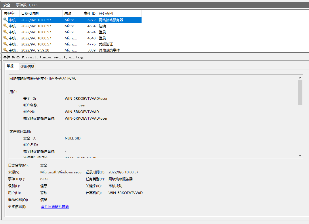
1. On the NPS server, view information about the online user.
Figure 81 Viewing user online information
2. On the switch, verify that the 802.1X or MAC authentication user is correctly assigned the specified authorization VLAN ID.
# Use the display dot1x connection command to display information about online 802.1X authentication users.
<Switch> display dot1x connection
Total connections: 1
Slot ID: 1
User MAC address: a036-9f8b-634c
Access interface: Ten-GigabitEthernet1/0/2
Username: user
User access state: Successful
Authentication domain: domain1
EAP packet identifier: 2
Authentication method: CHAP
AAA authentication method: RADIUS
Initial VLAN: 165
Authorization untagged VLAN: 100
Authorization tagged VLAN list: N/A
Authorization VSI: N/A
Authorization microsegment ID: N/A
Authorization ACL number/name: N/A
Authorization dynamic ACL name: N/A
Authorization user profile: N/A
Authorization CAR: N/A
Authorization URL: N/A
Authorization IPv6 URL: N/A
Authorization temporary redirect: Disabled
Start accounting: Successful
Real-time accounting-update failures: 0
Termination action: Default
Session timeout period: N/A
Online from: 2013/01/08 06:52:03
Online duration: 0h 0m 14s
# Use the display mac-authentication connection command to display information about online MAC authentication users.
[Switch]display mac-authentication connection
Total connections: 1
Slot ID: 1
User MAC address: 0010-9400-0005
Access interface: Ten-GigabitEthernet1/0/2
Username: 001094000005
User access state: Successful
Authentication domain: domain1
IPv4 address: 192.85.1.2
IPv4 address source: User packet
Initial VLAN: 165
Authorization untagged VLAN: 100
Authorization tagged VLAN: N/A
Authorization VSI: N/A
Authorization microsegment ID: N/A
Authorization ACL number/name: N/A
Authorization dynamic ACL name: N/A
Authorization user profile: N/A
Authorization CAR: N/A
Authorization URL: N/A
Authorization IPv6 URL: N/A
Authorization temporary redirect: Disabled
Start accounting: Successful
Real-time accounting-update failures: 0
Termination action: Default
Session timeout period: N/A
Offline detection: 300 sec (command-configured)
Online from: 2013/01/08 06:25:15
Online duration: 0h 0m 8s
Port-down keep online: Disabled (offline)
The output shows that VLAN 100 has been successfully assigned to the user.
Configuration files
The following takes 802.1X authentication as an example.
#
dot1x
#
interface Ten-GigabitEthernet1/0/2
port link-mode bridge
port link-type hybrid
port hybrid vlan 1 100 165 untagged
port hybrid pvid vlan 165
undo dot1x handshake
dot1x mandatory-domain domain1
undo dot1x multicast-trigger
dot1x port-method portbased
#
domain domain1
authentication lan-access radius-scheme radius1
authorization lan-access radius-scheme radius1
accounting lan-access radius-scheme radius1
#
radius scheme radius1
primary authentication 101.0.144.123
primary accounting 101.0.144.123
key authentication cipher $c$3$9jjl0lp5VA/WXEw065ZIT7j4AIN88XTF
key accounting cipher $c$3$fk1zm9nf2IFMdk+I7hGsyBcsAwqLobi7
user-name-format without-domain
#
Example: Configuring 802.1X or MAC authentication with VLAN name assignment
When you use a remote server to assign named authorization VLANs to users, you must create the VLANs and specify their names on the switch. This configuration is required for the switch to map the named authorization VLANs received from the server to their VLAN IDs.
Configuring the switch
1. Configure basic authentication settings:
¡ For MAC authentication users, configure the switch as described in "Configuring the switch."
¡ For 802.1X authentication users, configure the switch as described in "Configuring the switch."
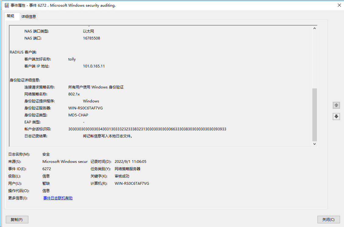
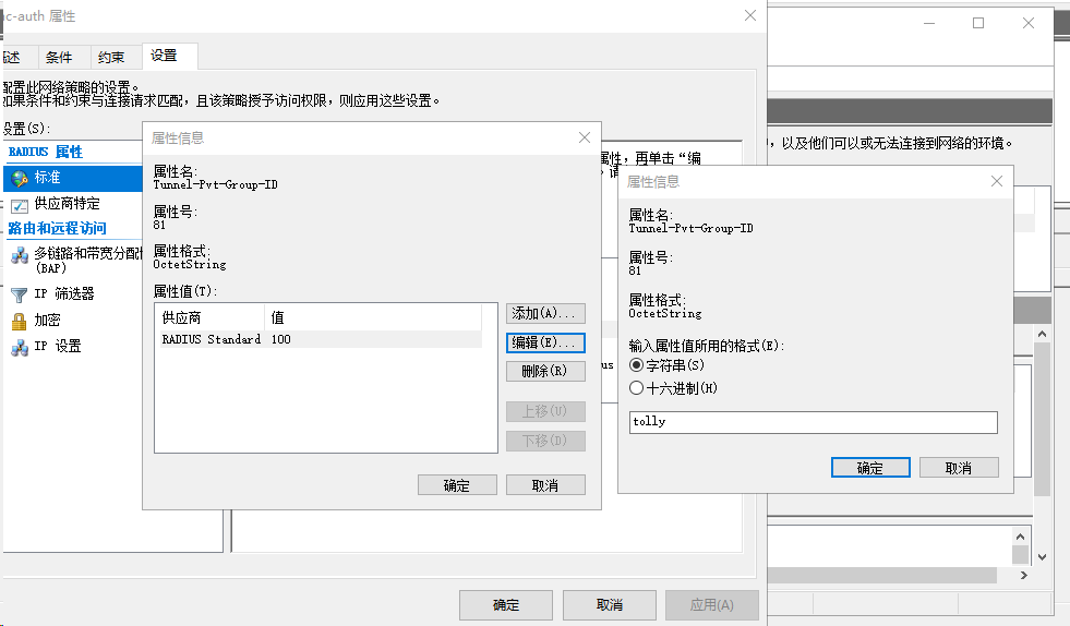
2. Create an authorization VLAN and assign a name to it. In this example, create VLAN 100 and set its name to tolly.
<Switch> system-view
[Switch] vlan 100
[Switch-vlan100] name tolly
Configuring the Windows Server 2016 NPS server
Configure basic settings:
· Configure the NPS server for MAC authentication users as described in "Configuring the Windows Server 2016 NPS server."
· Configure the NPS server for 802.1X users as described in "Configuring the Windows Server 2016 NPS server."
For VLAN name assignment, you must edit the RADIUS attributes on the Settings tab for the network policy as follows:
Figure 82 Specifying RADIUS attributes for the network policy
Verifying the configuration
1. On the NPS server, view information about the online user.
Figure 83 Viewing user online information
2. On the switch, verify that the 802.1X or MAC authentication user is correctly assigned the named authorization VLAN.
# Use the display dot1x connection command to display information about online 802.1X authentication users.
[Switch]display dot1x connection
Total connections: 1
Slot ID: 1
User MAC address: a036-9f8b-634c
Access interface: Ten-GigabitEthernet1/0/2
Username: user
User access state: Successful
Authentication domain: domain1
EAP packet identifier: 2
Authentication method: CHAP
AAA authentication method: RADIUS
Initial VLAN: 165
Authorization untagged VLAN: 100
Authorization tagged VLAN list: N/A
Authorization VSI: N/A
Authorization microsegment ID: N/A
Authorization ACL number/name: N/A
Authorization dynamic ACL name: N/A
Authorization user profile: N/A
Authorization CAR: N/A
Authorization URL: N/A
Authorization IPv6 URL: N/A
Authorization temporary redirect: Disabled
Start accounting: Successful
Real-time accounting-update failures: 0
Termination action: Default
Session timeout period: N/A
Online from: 2013/01/08 06:55:46
Online duration: 0h 0m 9s
# Use the display mac-authentication connection command to display information about online MAC authentication users.
[Switch]display mac-authentication connection
Total connections: 1
Slot ID: 1
User MAC address: 0010-9400-0005
Access interface: Ten-GigabitEthernet1/0/2
Username: 001094000005
User access state: Successful
Authentication domain: domain1
IPv4 address: 192.85.1.2
IPv4 address source: User packet
Initial VLAN: 165
Authorization untagged VLAN: 100
Authorization tagged VLAN: N/A
Authorization VSI: N/A
Authorization microsegment ID: N/A
Authorization ACL number/name: N/A
Authorization dynamic ACL name: N/A
Authorization user profile: N/A
Authorization CAR: N/A
Authorization URL: N/A
Authorization IPv6 URL: N/A
Authorization temporary redirect: Disabled
Start accounting: Successful
Real-time accounting-update failures: 0
Termination action: Default
Session timeout period: N/A
Offline detection: 300 sec (command-configured)
Online from: 2013/01/08 06:57:21
Online duration: 0h 0m 9s
Port-down keep online: Disabled (offline)
The output shows that VLAN 100 (named tolly) has been successfully assigned to the user.
Configuration files
The following takes 802.1X authentication as an example.
#
dot1x
#
interface Ten-GigabitEthernet1/0/2
port link-mode bridge
port link-type hybrid
port hybrid vlan 1 100 165 untagged
port hybrid pvid vlan 165
undo dot1x handshake
dot1x mandatory-domain domain1
undo dot1x multicast-trigger
dot1x port-method portbased
#
domain domain1
authentication lan-access radius-scheme radius1
authorization lan-access radius-scheme radius1
accounting lan-access radius-scheme radius1
#
radius scheme radius1
primary authentication 101.0.144.123
primary accounting 101.0.144.123
key authentication cipher $c$3$9jjl0lp5VA/WXEw065ZIT7j4AIN88XTF
key accounting cipher $c$3$fk1zm9nf2IFMdk+I7hGsyBcsAwqLobi7
user-name-format without-domain
#
Example: Configuring 802.1X or MAC authentication with VLAN group assignment
When you use a remote server to assign an authorization VLAN group to users, you must create the authorization VLAN group and assign a list of VLAN IDs to the group on the switch. This configuration is required for the switch to map the authorization VLAN group received from the server to the VLAN IDs in the VLAN group.
When the switch receives the authorization VLAN group for a user attached to a port, the switch assigns the lowest available VLAN ID in the VLAN group to that user. Then, the switch assigns the same VLAN to all subsequent users attached to that port.
Configuring the switch
1. Configure basic authentication settings:
¡ For MAC authentication users, configure the switch as described in "Configuring the switch."
¡ For 802.1X authentication users, configure the switch as described in "Configuring the switch."
2. Create an authorization VLAN group and add VLANs to it. In this example, create VLAN group temp and add VLANs 100, 200, and 300 to the group.
<Switch> system-view
[Switch] vlan-group temp
[Switch-vlan-group-temp] vlan-list 100 200 300
Configuring the Windows Server 2016 NPS server
Configure basic settings:
· Configure the NPS server for MAC authentication users as described in "Configuring the Windows Server 2016 NPS server."
· Configure the NPS server for 802.1X users as described in "Configuring the Windows Server 2016 NPS server."
For VLAN group name assignment, you must edit the RADIUS attributes on the Settings tab for the network policy as follows:
Figure 84 Specifying RADIUS attributes for the network policy

Verifying the configuration
1. On the NPS server, view information about the online user.
Figure 85 Viewing user online information

2. On the switch, verify that the online 802.1X or MAC authentication user is correctly assigned a VLAN ID selected from the authorization VLAN group.
# Use the display dot1x connection command to display information about online 802.1X authentication users.
<Switch> display dot1x connection
Total connections: 1
Slot ID: 1
User MAC address: a036-9f8b-634c
Access interface: Ten-GigabitEthernet1/0/2
Username: user
User access state: Successful
Authentication domain: domain1
EAP packet identifier: 2
Authentication method: CHAP
AAA authentication method: RADIUS
Initial VLAN: 165
Authorization untagged VLAN: 100
Authorization tagged VLAN list: N/A
Authorization VSI: N/A
Authorization microsegment ID: N/A
Authorization ACL number/name: N/A
Authorization dynamic ACL name: N/A
Authorization user profile: N/A
Authorization CAR: N/A
Authorization URL: N/A
Authorization IPv6 URL: N/A
Authorization temporary redirect: Disabled
Start accounting: Successful
Real-time accounting-update failures: 0
Termination action: Default
Session timeout period: N/A
Online from: 2013/01/08 07:03:17
Online duration: 0h 0m 12s
# Use the display mac-authentication connection command to display information about online MAC authentication users.
<Switch> display mac-authentication connection
Total connections: 1
Slot ID: 1
User MAC address: 0010-9400-0005
Access interface: Ten-GigabitEthernet1/0/2
Username: 001094000005
User access state: Successful
Authentication domain: domain1
IPv4 address: 192.85.1.2
IPv4 address source: User packet
Initial VLAN: 165
Authorization untagged VLAN: 100
Authorization tagged VLAN: N/A
Authorization VSI: N/A
Authorization microsegment ID: N/A
Authorization ACL number/name: N/A
Authorization dynamic ACL name: N/A
Authorization user profile: N/A
Authorization CAR: N/A
Authorization URL: N/A
Authorization IPv6 URL: N/A
Authorization temporary redirect: Disabled
Start accounting: Successful
Real-time accounting-update failures: 0
Termination action: Default
Session timeout period: N/A
Offline detection: 300 sec (command-configured)
Online from: 2013/01/08 06:57:21
Online duration: 0h 10m 12s
Port-down keep online: Disabled (offline)
The output shows that VLAN 100 from VLAN group temp has been successfully assigned to the user.
Configuration files
The following takes 802.1X authentication as an example.
#
dot1x
#
interface Ten-GigabitEthernet1/0/2
port link-mode bridge
port link-type hybrid
port hybrid vlan 1 100 165 untagged
port hybrid pvid vlan 165
undo dot1x handshake
dot1x mandatory-domain domain1
undo dot1x multicast-trigger
dot1x port-method portbased
#
domain domain1
authentication lan-access radius-scheme radius1
authorization lan-access radius-scheme radius1
accounting lan-access radius-scheme radius1
#
radius scheme radius1
primary authentication 101.0.144.123
primary accounting 101.0.144.123
key authentication cipher $c$3$9jjl0lp5VA/WXEw065ZIT7j4AIN88XTF
key accounting cipher $c$3$fk1zm9nf2IFMdk+I7hGsyBcsAwqLobi7
user-name-format without-domain
#
Example: Configuring 802.1X or MAC authentication with multiple VLANs assignment
When you use a remote server to assign multiple named authorization VLANs to users, you must create the authorization VLANs and assign names to them on the switch. This configuration is required for the switch to map the named authorization VLANs received from the server to their VLAN IDs.
When the switch selects a VLAN for a user from the set of server-assigned authorization VLANs, the switch preferentially selects the lowest available VLAN ID from among them.
Configuring the switch
1. Configure basic authentication settings:
¡ For MAC authentication users, configure the switch as described in "Configuring the switch."
¡ For 802.1X authentication users, configure the switch as described in "Configuring the switch."
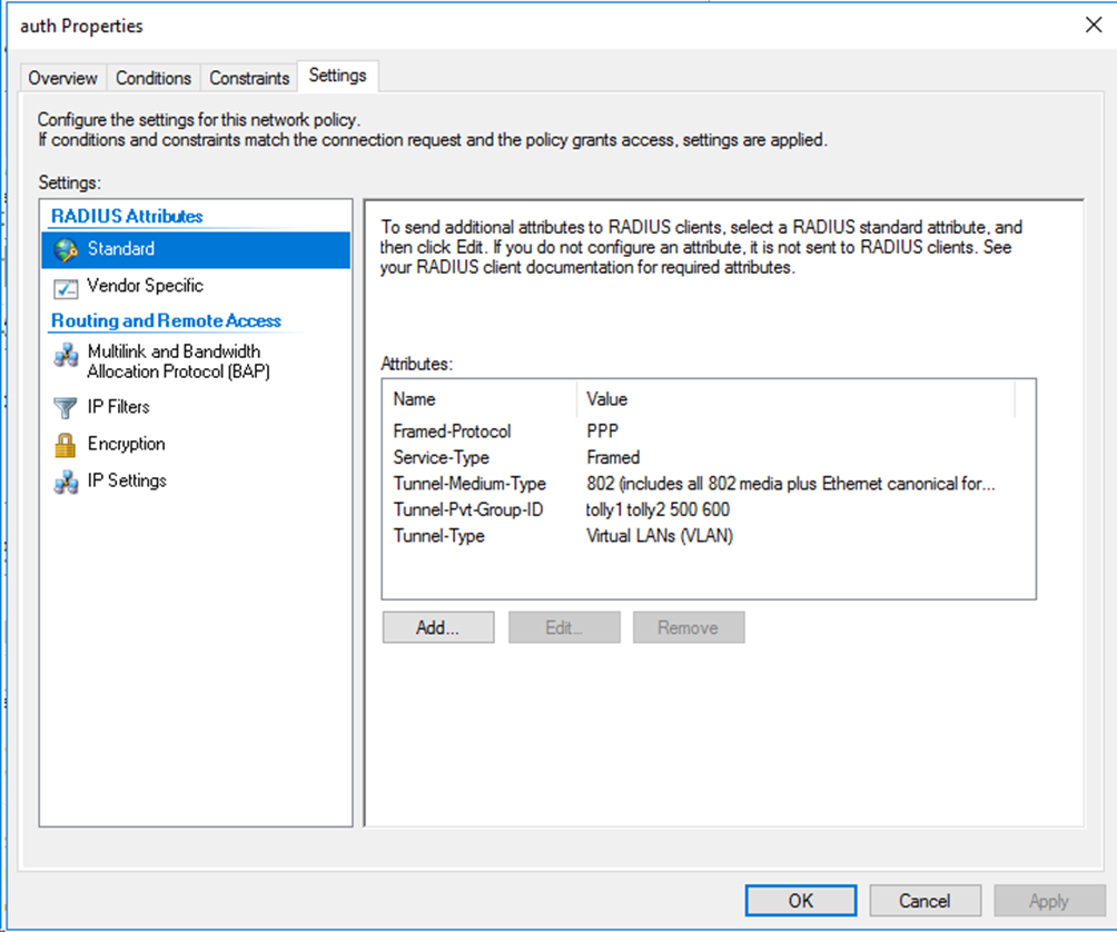
2. Create named authorization VLANs and assign names to them. In this example, create VLANs 100 and 200, and assign name tolly1 to VLAN 100 and name tolly2 to VLAN 200.
[Switch] vlan 100
[Switch-vlan100] name tolly1
[Switch-vlan100] quit
[Switch] vlan 200
[Switch-vlan200] name tolly2
[Switch-vlan200] quit
Configuring the Windows Server 2016 NPS server
Configure basic settings:
· Configure the NPS server for MAC authentication users as described in "Configuring the Windows Server 2016 NPS server."
· Configure the NPS server for 802.1X users as described in "Configuring the Windows Server 2016 NPS server."
For multiple VLANs assignment, you must edit the RADIUS attributes on the Settings tab for the network policy as follows:
Figure 86 Specifying RADIUS attributes for the network policy
Verifying the configuration
1. On the NPS server, view information about the online user.
Figure 87 Viewing user online information
2. On the switch, verify that the online 802.1X or MAC authentication user is correctly assigned a VLAN selected from the assigned set of authorization VLAN IDs and names.
# Use the display dot1x connection command to display information about online 802.1X authentication users.
<Switch> display dot1x connection
Total connections: 1
Slot ID: 1
User MAC address: a036-9f8b-634c
Access interface: Ten-GigabitEthernet1/0/2
Username: user
User access state: Successful
Authentication domain: domain1
EAP packet identifier: 2
Authentication method: CHAP
AAA authentication method: RADIUS
Initial VLAN: 165
Authorization untagged VLAN: 100
Authorization tagged VLAN list: N/A
Authorization VSI: N/A
Authorization microsegment ID: N/A
Authorization ACL number/name: N/A
Authorization dynamic ACL name: N/A
Authorization user profile: N/A
Authorization CAR: N/A
Authorization URL: N/A
Authorization IPv6 URL: N/A
Authorization temporary redirect: Disabled
Start accounting: Successful
Real-time accounting-update failures: 0
Termination action: Default
Session timeout period: N/A
Online from: 2013/01/08 21:33:14
Online duration: 0h 0m 12s
The output shows that VLAN 100 has been selected from the set of server-assigned authorization VLANs and assigned to the user.
# Use the display mac-authentication connection command to display information about online MAC authentication users. (Details not shown.)
Configuration files
The following takes 802.1X authentication as an example.
#
dot1x
#
interface Ten-GigabitEthernet1/0/2
port link-mode bridge
port link-type hybrid
port hybrid vlan 1 100 165 untagged
port hybrid pvid vlan 165
undo dot1x handshake
dot1x mandatory-domain domain1
undo dot1x multicast-trigger
dot1x port-method portbased
#
domain domain1
authentication lan-access radius-scheme radius1
authorization lan-access radius-scheme radius1
accounting lan-access radius-scheme radius1
#
radius scheme radius1
primary authentication 101.0.144.123
primary accounting 101.0.144.123
key authentication cipher $c$3$9jjl0lp5VA/WXEw065ZIT7j4AIN88XTF
key accounting cipher $c$3$fk1zm9nf2IFMdk+I7hGsyBcsAwqLobi7
user-name-format without-domain
#
Examples: Configuring 802.1X authentication with assignment of VLAN IDs with the tagged or untagged attribute
Restrictions and guidelines
To assign VLAN IDs with the tagged or untagged attribute suffix, make sure the user access port is a hybrid or trunk port that performs port-based access control. For users attached to an access port, assignment of VLANs with the tagged or untagged attribute suffix cannot take effect and they will be unable to come online.
Example: Configuring 802.1X authentication with automatic assignment of only tagged VLANs
When you configure the remote server to assign only tagged VLANs to users, the PVID (default VLAN ID) of the port does not change.
Configuring the switch
Configure the switch as described in "Configuring the switch."
Configuring the Windows Server 2016 NPS server
Configure the NPS server as described in "Configuring the Windows Server 2016 NPS server."
To assign tagged VLANs to users, you must edit the RADIUS attributes on the Settings tab for the network policy as follows:
Figure 88 Specifying RADIUS attributes for the network policy
Verifying the configuration
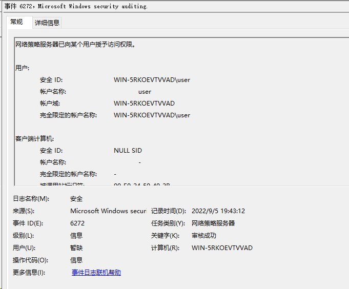
1. On the NPS server, view information about the online user.
Figure 89 Viewing user online information
2. On the switch, verify that the online 802.1X authentication user is correctly assigned the specified VLAN information.
# Use the display dot1x connection command to display information about online 802.1X authentication users.
<Switch> display dot1x connection
Total connections: 1
Slot ID: 1
User MAC address: a036-9f8b-634c
Access interface: Ten-GigabitEthernet1/0/2
Username: user
User access state: Successful
Authentication domain: domain1
EAP packet identifier: 2
Authentication method: CHAP
AAA authentication method: RADIUS
Initial VLAN: 165
Authorization untagged VLAN: 100
Authorization tagged VLAN list: 7 9
Authorization VSI: N/A
Authorization microsegment ID: N/A
Authorization ACL number/name: N/A
Authorization dynamic ACL name: N/A
Authorization user profile: N/A
Authorization CAR: N/A
Authorization URL: N/A
Authorization IPv6 URL: N/A
Authorization temporary redirect: Disabled
Start accounting: Successful
Real-time accounting-update failures: 0
Termination action: Default
Session timeout period: N/A
Online from: 2013/01/08 07:15:29
Online duration: 0h 0m 10s
The output shows that tagged VLANs 7 and 9 have been successfully assigned to the user. Because no untagged VLANs have been specified on the server, the PVID of the user-attached port remains unchanged.
Configuration files
#
dot1x
#
interface Ten-GigabitEthernet1/0/2
port link-mode bridge
port link-type hybrid
port hybrid vlan 1 100 165 untagged
port hybrid pvid vlan 165
undo dot1x handshake
dot1x mandatory-domain domain1
undo dot1x multicast-trigger
dot1x port-method portbased
#
domain domain1
authentication lan-access radius-scheme radius1
authorization lan-access radius-scheme radius1
accounting lan-access radius-scheme radius1
#
radius scheme radius1
primary authentication 101.0.144.123
primary accounting 101.0.144.123
key authentication cipher $c$3$9jjl0lp5VA/WXEw065ZIT7j4AIN88XTF
key accounting cipher $c$3$fk1zm9nf2IFMdk+I7hGsyBcsAwqLobi7
user-name-format without-domain
#
Example: Configuring 802.1X authentication with assignment of VLANs that contain one untagged VLAN
When you configure the remote server to assign a VLAN string containing one untagged VLAN, the untagged VLAN becomes the PVID of the port.
Configuring the switch
Configure the switch as described in "Configuring the switch."
Configuring the Windows Server 2016 NPS server
Configure the NPS server as described in "Configuring the Windows Server 2016 NPS server."
For assignment of a VLAN string containing an untagged VLAN, you must edit the RADIUS attributes on the Settings tab for the network policy as follows:
Figure 90 Specifying RADIUS attributes for the network policy

Verifying the configuration
1. On the NPS server, view information about the online user.
Figure 91 Viewing user online information

2. On the switch, verify that the online 802.1X authentication user is correctly assigned the specified VLAN information.
# Use the display dot1x connection command to display information about online 802.1X authentication users.
<Switch> display dot1x connection
Total connections: 1
Slot ID: 1
User MAC address: a036-9f8b-634c
Access interface: Ten-GigabitEthernet1/0/2
Username: user
User access state: Successful
Authentication domain: domain1
EAP packet identifier: 2
Authentication method: CHAP
AAA authentication method: RADIUS
Initial VLAN: 165
Authorization untagged VLAN: 10
Authorization tagged VLAN list: 7 9
Authorization VSI: N/A
Authorization microsegment ID: N/A
Authorization ACL number/name: N/A
Authorization dynamic ACL name: N/A
Authorization user profile: N/A
Authorization CAR: N/A
Authorization URL: N/A
Authorization IPv6 URL: N/A
Authorization temporary redirect: Disabled
Start accounting: Successful
Real-time accounting-update failures: 0
Termination action: Default
Session timeout period: N/A
Online from: 2013/01/08 07:19:07
Online duration: 0h 0m 10s
The output shows that tagged VLAN 7, tagged VLAN 9, and untagged VLAN 10 have been successfully assigned to the user. The PVID of the port has changed to VLAN 10.
Configuration files
#
dot1x
#
interface Ten-GigabitEthernet1/0/2
port link-mode bridge
port link-type hybrid
port hybrid vlan 1 100 165 untagged
port hybrid pvid vlan 165
undo dot1x handshake
dot1x mandatory-domain domain1
undo dot1x multicast-trigger
dot1x port-method portbased
#
domain domain1
authentication lan-access radius-scheme radius1
authorization lan-access radius-scheme radius1
accounting lan-access radius-scheme radius1
#
radius scheme radius1
primary authentication 101.0.144.123
primary accounting 101.0.144.123
key authentication cipher $c$3$9jjl0lp5VA/WXEw065ZIT7j4AIN88XTF
key accounting cipher $c$3$fk1zm9nf2IFMdk+I7hGsyBcsAwqLobi7
user-name-format without-domain
#
Example: Configuring 802.1X authentication with assignment of VLANs that contain multiple untagged VLANs
When you configure the remote server to assign a set of VLANs that contain multiple untagged VLANs, the switch selects the leftmost VLAN ID without a suffix or the leftmost VLAN ID with a suffix of u as the authorization untagged VLAN, whichever is more leftward. The remaining VLAN IDs with a suffix of u or without a suffix will be assigned as tagged VLANs. On the switch, the PVID of the user-attached port will change to the untagged authorization VLAN.
Configuring the switch
Configure the switch as described in "Configuring the switch."
Configuring the Windows Server 2016 NPS server
Configure the NPS server as described in "Configuring the Windows Server 2016 NPS server."
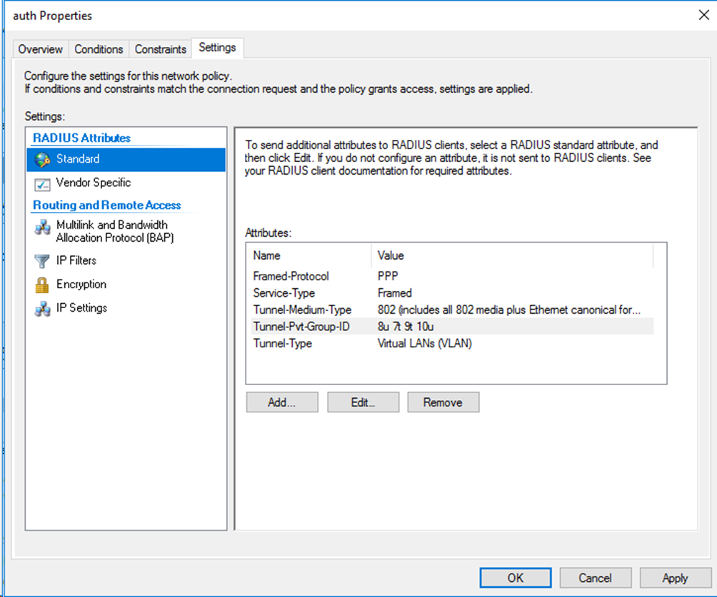
To assign multiple tagged and untagged VLANs to a user, you must edit the RADIUS attributes on the Settings tab for the network policy as follows:
Figure 92 Specifying RADIUS attributes for the network policy
Verifying the configuration
1. On the NPS server, view information about the online user.
Figure 93 Viewing user online information
2. On the switch, verify that the online 802.1X authentication user is correctly assigned the specified VLAN information.
# Use the display dot1x connection command to display information about online 802.1X authentication users.
[Switch]display dot1x connection
Total connections: 1
Slot ID: 1
User MAC address: a036-9f8b-634c
Access interface: Ten-GigabitEthernet1/0/2
Username: user
User access state: Successful
Authentication domain: domain1
EAP packet identifier: 2
Authentication method: CHAP
AAA authentication method: RADIUS
Initial VLAN: 165
Authorization untagged VLAN: 8
Authorization tagged VLAN list: 7 9-10
Authorization VSI: N/A
Authorization microsegment ID: N/A
Authorization ACL number/name: N/A
Authorization dynamic ACL name: N/A
Authorization user profile: N/A
Authorization CAR: N/A
Authorization URL: N/A
Authorization IPv6 URL: N/A
Authorization temporary redirect: Disabled
Start accounting: Successful
Real-time accounting-update failures: 0
Termination action: Default
Session timeout period: N/A
Online from: 2013/01/08 07:22:52
Online duration: 0h 0m 48s
The output shows that tagged VLAN 7, VLAN 9, and VLAN 10, and untagged VLAN 8 have been assigned to the user. In addition, the PVID of the port has changed to VLAN 8.
Configuration files
#
dot1x
#
interface Ten-GigabitEthernet1/0/2
port link-mode bridge
port link-type hybrid
port hybrid vlan 1 100 165 untagged
port hybrid pvid vlan 165
undo dot1x handshake
dot1x mandatory-domain domain1
undo dot1x multicast-trigger
dot1x port-method portbased
#
domain domain1
authentication lan-access radius-scheme radius1
authorization lan-access radius-scheme radius1
accounting lan-access radius-scheme radius1
#
radius scheme radius1
primary authentication 101.0.144.123
primary accounting 101.0.144.123
key authentication cipher $c$3$9jjl0lp5VA/WXEw065ZIT7j4AIN88XTF
key accounting cipher $c$3$fk1zm9nf2IFMdk+I7hGsyBcsAwqLobi7
user-name-format without-domain
#
Example: Configuring 802.1X or MAC authentication with ACL assignment
Network configuration
As shown in Figure 94, configure the switch to work in conjunction with the Windows Server 2016 NPS server to perform 802.1X or MAC authentication for the client. The client must pass 802.1X or MAC to access network resources.
Configure the switch as follows:
· Use the NPS server as the RADIUS server to perform 802.1X or MAC authentication for the client.
· Configure the NPS server to assign an authorization ACL to the client access port after the client passes 802.1X or MAC authentication.
Software versions used
This configuration example was created and verified on the following hardware and software versions:
|
Hardware |
Software version |
|
S5560X-54C-PWR-EI switch |
Version 7.1.070 |
|
Authentication server |
Windows Server 2016 NPS |
Procedures
When you configure the remote server to assign an ACL to users, make sure the ACL has been created on the switch.
Configuring the switch
1. Configure basic authentication settings:
¡ For MAC authentication users, configure the switch as described in "Configuring the switch."
¡ For 802.1X authentication users, configure the switch as described in "Configuring the switch."
2. Configure advanced ACL rule 3001 to permit all packets sourced from any source IP address.
<Switch> system-view
[Switch] acl advanced 3001
[Switch-acl-ipv4-adv-3001] rule 0 permit ip source any
Configuring the Windows Server 2016 NPS server
Configure basic settings:
· Configure the NPS server for MAC authentication users as described in "Configuring the Windows Server 2016 NPS server."
· Configure the NPS server for 802.1X users as described in "Configuring the Windows Server 2016 NPS server."
For ACL assignment, you must edit the RADIUS attributes on the Settings tab for the network policy as follows:
Figure 95 Specifying RADIUS attributes for the network policy

|
|
NOTE: If the value for the Filter-Id attribute is a number, the switch treats that number as an ACL number. If the value is not a number, the switch treats that value as a user profile. |
Verifying the configuration
1. On the NPS server, view information about the online user.
Figure 96 Viewing user online information
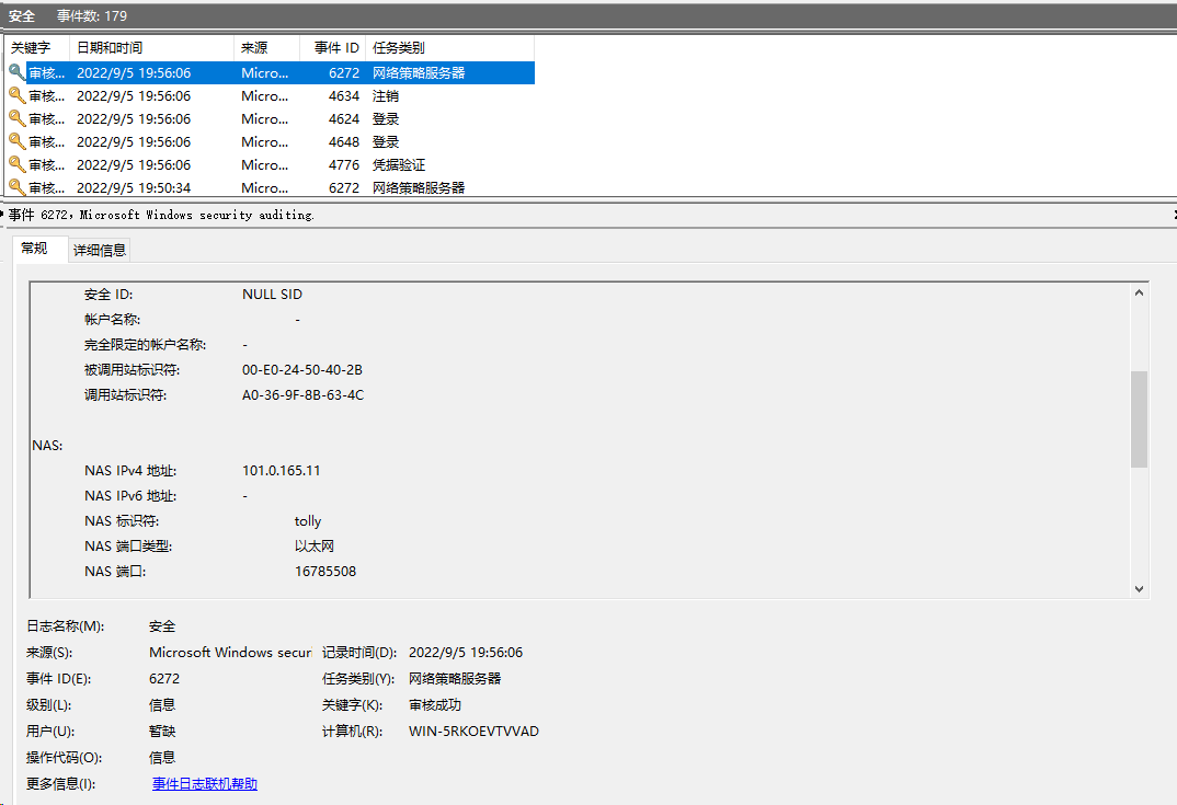
2. On the switch, verify that the user is correctly assigned the specified ACL.
# Use the display dot1x connection command to display information about online 802.1X authentication users.
<Switch> display dot1x connection
Total connections: 1
Slot ID: 1
User MAC address: a036-9f8b-634c
Access interface: Ten-GigabitEthernet1/0/2
Username: user
User access state: Successful
Authentication domain: domain1
EAP packet identifier: 2
Authentication method: CHAP
AAA authentication method: RADIUS
Initial VLAN: 165
Authorization untagged VLAN: N/A
Authorization tagged VLAN list: N/A
Authorization VSI: N/A
Authorization microsegment ID: N/A
Authorization ACL number/name: 3001
Authorization dynamic ACL name: N/A
Authorization user profile: N/A
Authorization CAR: N/A
Authorization URL: N/A
Authorization IPv6 URL: N/A
Authorization temporary redirect: Disabled
Start accounting: Successful
Real-time accounting-update failures: 0
Termination action: Default
Session timeout period: N/A
Online from: 2013/01/08 07:28:24
Online duration: 0h 0m 12s
The output shows that ACL 3001 has been successfully assigned to the user.
# Use the display mac-authentication connection command to display information about online MAC authentication users. (Details not shown.)
Configuration files
The following takes 802.1X authentication as an example.
#
dot1x
#
interface Ten-GigabitEthernet1/0/2
port link-mode bridge
port link-type hybrid
port hybrid vlan 1 100 165 untagged
port hybrid pvid vlan 165
undo dot1x handshake
dot1x mandatory-domain domain1
undo dot1x multicast-trigger
dot1x port-method portbased
#
domain domain1
authentication lan-access radius-scheme radius1
authorization lan-access radius-scheme radius1
accounting lan-access radius-scheme radius1
#
radius scheme radius1
primary authentication 101.0.144.123
primary accounting 101.0.144.123
key authentication cipher $c$3$9jjl0lp5VA/WXEw065ZIT7j4AIN88XTF
key accounting cipher $c$3$fk1zm9nf2IFMdk+I7hGsyBcsAwqLobi7
user-name-format without-domain
#
Example: Configuring 802.1X or MAC authentication with user profile assignment
Network configuration
As shown in Figure 97, configure the switch to work in conjunction with the Windows Server 2016 NPS server to perform 802.1X or MAC authentication for the client. The client must pass 802.1X or MAC authentication to access network resources.
Configure the switch as follows:
· Use the NPS server as the RADIUS server to perform 802.1X or MAC authentication for the client.
· Configure the NPS server to assign an authorization user profile to the client after the client passes 802.1X or MAC authentication.

Software versions used
This configuration example was created and verified on the following hardware and software versions:
|
Hardware |
Software version |
|
S5560X-54C-PWR-EI switch |
Version 7.1.070 |
|
Authentication server |
Windows Server 2016 NPS |
Procedures
When you use the remote server to assign a user profile to users, make sure the user profile has been created on the switch.
Configuring the switch
1. Configure basic authentication settings:
¡ For MAC authentication users, configure the switch as described in "Configuring the switch."
¡ For 802.1X authentication users, configure the switch as described in "Configuring the switch."
2. Create user profile test for the user and set the CIR to 100000 kbps for incoming traffic sent by the user profile.
<Switch> system-view
[Switch] user-profile test
[Switch-user-profile-test]qos car inbound any cir 100000
[Switch-user-profile-test] quit
Configuring the Windows Server 2016 NPS server
Configure basic settings:
· Configure the NPS server for MAC authentication users as described in "Configuring the Windows Server 2016 NPS server."
· Configure the NPS server for 802.1X users as described in "Configuring the Windows Server 2016 NPS server."
For user profile assignment, you must edit the RADIUS attributes on the Settings tab for the network policy as follows:
Figure 98 Specifying RADIUS attributes for the network policy
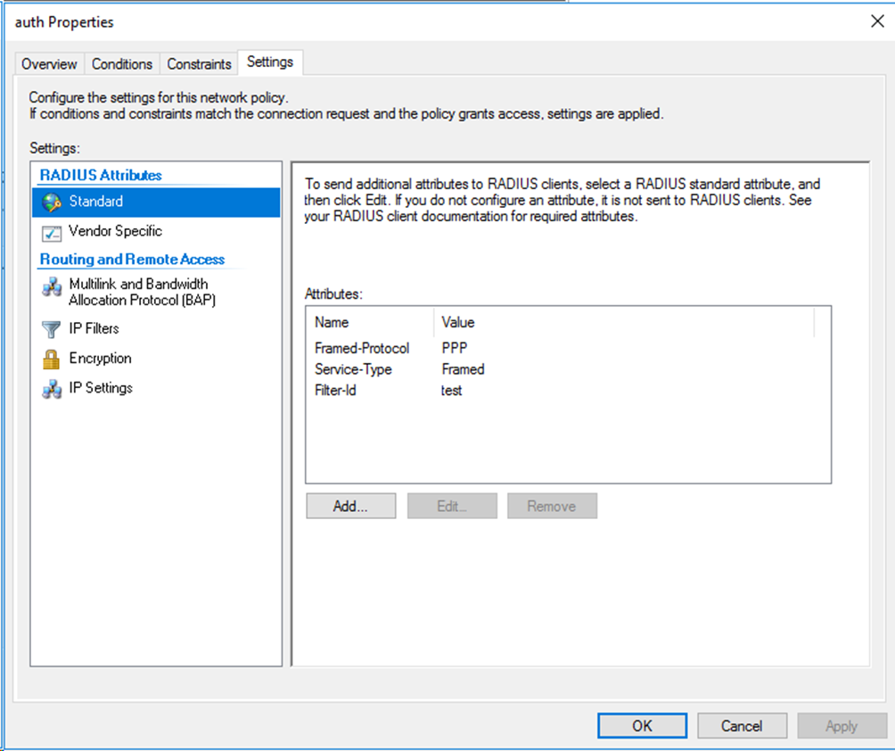
|
|
NOTE: If the value for the Filter-Id attribute is a number, the switch treats that number as an ACL number. If the value is not a number, the switch treats that value as a user profile. |
Verifying the configuration
The following takes 802.1X authentication as an example.
1. On the NPS server, view information about the online user.
Figure 99 Viewing user online information

2. On the switch, verify that the user is correctly assigned the specified user profile.
# Use the display dot1x connection command to display information about online 802.1X authentication users.
<Switch> display dot1x connection
Total connections: 1
Slot ID: 1
User MAC address: a036-9f8b-634c
Access interface: Ten-GigabitEthernet1/0/2
Username: user
User access state: Successful
Authentication domain: domain1
EAP packet identifier: 2
Authentication method: CHAP
AAA authentication method: RADIUS
Initial VLAN: 165
Authorization untagged VLAN: N/A
Authorization tagged VLAN list: N/A
Authorization VSI: N/A
Authorization microsegment ID: N/A
Authorization ACL number/name: N/A
Authorization dynamic ACL name: N/A
Authorization user profile: test
Authorization CAR: N/A
Authorization URL: N/A
Authorization IPv6 URL: N/A
Authorization temporary redirect: Disabled
Start accounting: Successful
Real-time accounting-update failures: 0
Termination action: Default
Session timeout period: N/A
Online from: 2013/01/10 07:29:38
Online duration: 0h 0m 50s
The output shows that user profile test has been successfully assigned to the user.
Configuration files
The following takes 802.1X authentication as an example.
#
dot1x
#
interface Ten-GigabitEthernet1/0/2
port link-mode bridge
port link-type hybrid
port hybrid vlan 1 100 165 untagged
port hybrid pvid vlan 165
undo dot1x handshake
dot1x mandatory-domain domain1
undo dot1x multicast-trigger
dot1x port-method portbased
#
domain domain1
authentication lan-access radius-scheme radius1
authorization lan-access radius-scheme radius1
accounting lan-access radius-scheme radius1
#
radius scheme radius1
primary authentication 101.0.144.123
primary accounting 101.0.144.123
key authentication cipher $c$3$9jjl0lp5VA/WXEw065ZIT7j4AIN88XTF
key accounting cipher $c$3$fk1zm9nf2IFMdk+I7hGsyBcsAwqLobi7
user-name-format without-domain
#
