- Table of Contents
-
- H3C S12500CR Switch Router Series Installation Guide-6W101
- 00-Preface
- 01-Chapter 1 Preparing for Installation
- 02-Chapter 2 Installing the Device
- 03-Chapter 3 Installing Removable Components
- 04-Chapter 4 Connecting Your Device to the Network
- 05-Chapter 5 Troubleshooting
- 06-Chapter 6 Replacement Procedures
- 07-Appendix A Engineering labels
- 08-Appendix B Cabling Recommendations
- 09-Appendix C Repackaging the Device
- Related Documents
-
| Title | Size | Download |
|---|---|---|
| 03-Chapter 3 Installing Removable Components | 2.85 MB |
Installing removable components
Removing the filler panel from a fan tray slot
Installing power supplies and power trays
Power trays and power supplies
(Optional) Installing power trays
Installing the air filter in the top hood
Installing transceiver modules
Installing a transceiver module
Installing removable components
|
|
WARNING! · As a best practice, connect power cords after installing all required removable components. · Long-time exposure to strong air flow might cause discomfort. To avoid this hazard, do not stand close to the air outlet vents while the device is operating. If you must be next to the device on the air outlet vent side for an extended period, avoid the air flow or take other protective measures. |
|
|
CAUTION: For adequate ventilation and heat dissipation, install filler panels in unused slots. |
|
|
TIP: Keep the chassis and the component packaging materials, such as cartons and bags, secure for future use. |
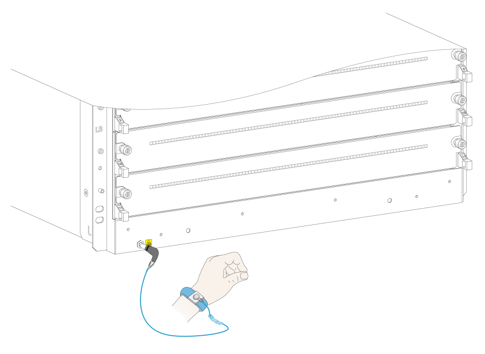
Attaching an ESD wrist strap
The device is provided with an ESD wrist strap. To minimize ESD damage to electronic components, wear the ESD wrist strap and make sure it is reliably grounded before you install removable components.
To attach an ESD wrist strap:
1. Make sure the device is reliably grounded. For information about how to ground your device, see "Installing the device."
2. Put on the wrist strap.
3. Tighten the wrist strap to make sure it makes good skin contact. Make sure the resistance reading between your body and the ground is between 1 and 10 megohms.
4. As shown in Figure 1, insert the ESD wrist strap into the ESD jack on the chassis.
Figure 1 Attaching an ESD wrist strap
|
(1) ESD jack (with an ESD sign) |
Installing modules
|
|
CAUTION: Before installing a module on the device, make sure the connectors of the module are not damaged or blocked. |
Unless otherwise stated, the term "module" collectively refers to SEUs (MPUs), environment management modules, interface modules, and fabric modules. All these modules are hot swappable.
For the SEUs, environment management modules, interface modules, and fabric modules available for the device, see H3C S12500R Switch Router Series Hardware Information and Specifications.
Installing SEUs
Restrictions and guidelines
· To avoid module damage and ensure correct module operation, make sure the SEU model matches the interface module, environment management module, and fabric module models.
¡ Type K SEUs can operate together only with Type K interface modules, environment management module LSXM1CMUR1, and Type K fabric modules. Type K interface modules have a character of K in their identifiers, for example, LSXM1CGQ48KBR1. Type K fabric modules have a character string of SFK in their identifiers, for example, LSXM1SFK08GR1.
¡ Type S SEUs can operate together only with Type S interface modules, Type S environment management modules, and Type S fabric modules. Type S interface modules have a character of S in their identifiers, for example, LSXM3TGS48SF2. Type S environment management modules have a character of S in their identifiers, for example, LSXM1CMURS2. Type S fabric modules have a character of S in their identifiers, for example, LSXM3SFS08F2.
· If you are not to install an SEU in an SEU slot, keep the filler panel in the slot.
· When you install an SEU, avoid damaging the connectors on the SEU.
· To prevent a filler panel from being drawn into the chassis when fan speed is high, use both hands to grasp the filler panel by its two sides during filler panel installation and removal on an operating device.
Procedure
You can install one SEU, or two SEUs for redundancy on the device. To install one SEU, you can install it in either of the SEU slots.
The ejector levers of the SEUs are pink marked. The ejector lever pillow blocks on the SEU slots are also pink marked.
The SEU installation procedure is the same for the S12516CR and S12508CR Ethernet switches routers. The following procedure installs an SEU on an S12516CR switch router.
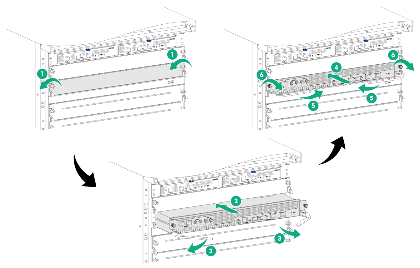
To install an SEU:
1. As shown by callout 1 in Figure 2, remove the filler panel from the target SEU slot.
Keep the removed filler panel secure for future use.
2. As shown by callout 2 in Figure 2, holding the two sides of the SEU firmly, push it slowly and steadily into the slot along the guide rails.
3. As shown by callout 3 in Figure 2, pull the ejector levers of the SEU outward when most part of the SEU is inserted in the slot.
4. Push the SEU until the brakes on its ejector levers touch the slot edges tightly.
5. As shown by callout 4 in Figure 2, continue to push the SEU by its middle part on the front panel until you cannot move it.
6. As shown by callout 5 in Figure 2, push the ejector levers inward until they come in close contact with the front panel.
7. As shown by callout 6 in Figure 2, fasten the captive screws on the SEU. As a best practice, fasten each captive screw to a torque of 5 kgf-cm (0.49 Nm).
Figure 2 Installing an SEU (S12516CR)

Installing interface modules
Restrictions and guidelines
· To avoid module damage and ensure correct module operation, make sure the interface module model matches the SEU, environment management module, and fabric module models.
¡ Type K interface modules can operate together only with Type K SEUs, environment management module LSXM1CMUR1, and Type K fabric modules. Type K SEUs have a character of K in their identifiers, for example, LSXM1SUPKR1. Type K fabric modules have a character string of SFK in their identifiers, for example, LSXM1SFK08GR1.
¡ Type S interface modules can operate together only with Type S SEUs, Type S environment management modules, and Type S fabric modules. Type S SEUs have a character of S in their identifiers, for example, LSXM1SUPRS2. Type S environment management modules have a character of S in their identifiers, for example, LSXM1CMURS2. Type S fabric modules have a character of S in their identifiers, for example, LSXM3SFS08F2.
· To install an S12500R interface modules with dimensions of 50 × 432.6 × 519.8 mm (1.97 × 17.03 × 20.46 in) or Type S interface module (for example, LSXM3TGS48SF2) in an interface module slot on the switch, you must first install an interface module adapter in the interface module slot. For the interface module adapter installation method, see H3C S12500CR LSXM1IMAA Interface Module Adapter User Manual.
· If a slot has an interface module adapter installed, you must install an interface module in the slot. If you are not to install an interface module in the slot, remove the interface module adapter and then install a filler panel in the slot for adequate heat dissipation.
· Before installing an interface module in an interface module slot, make sure a module or filler panel is present in the slot below the interface module slot.
· When you install or remove a filler panel while the device is operating, hold both sides of the filler panel firmly with two hands. The filler panel might be drawn into the chassis when the fan speed is high.
Procedure
The ejector levers of the interface modules are purple marked. The ejector lever pillow blocks on the interface module slots have purple marks are also purple marked to indicate the interface module installation location.
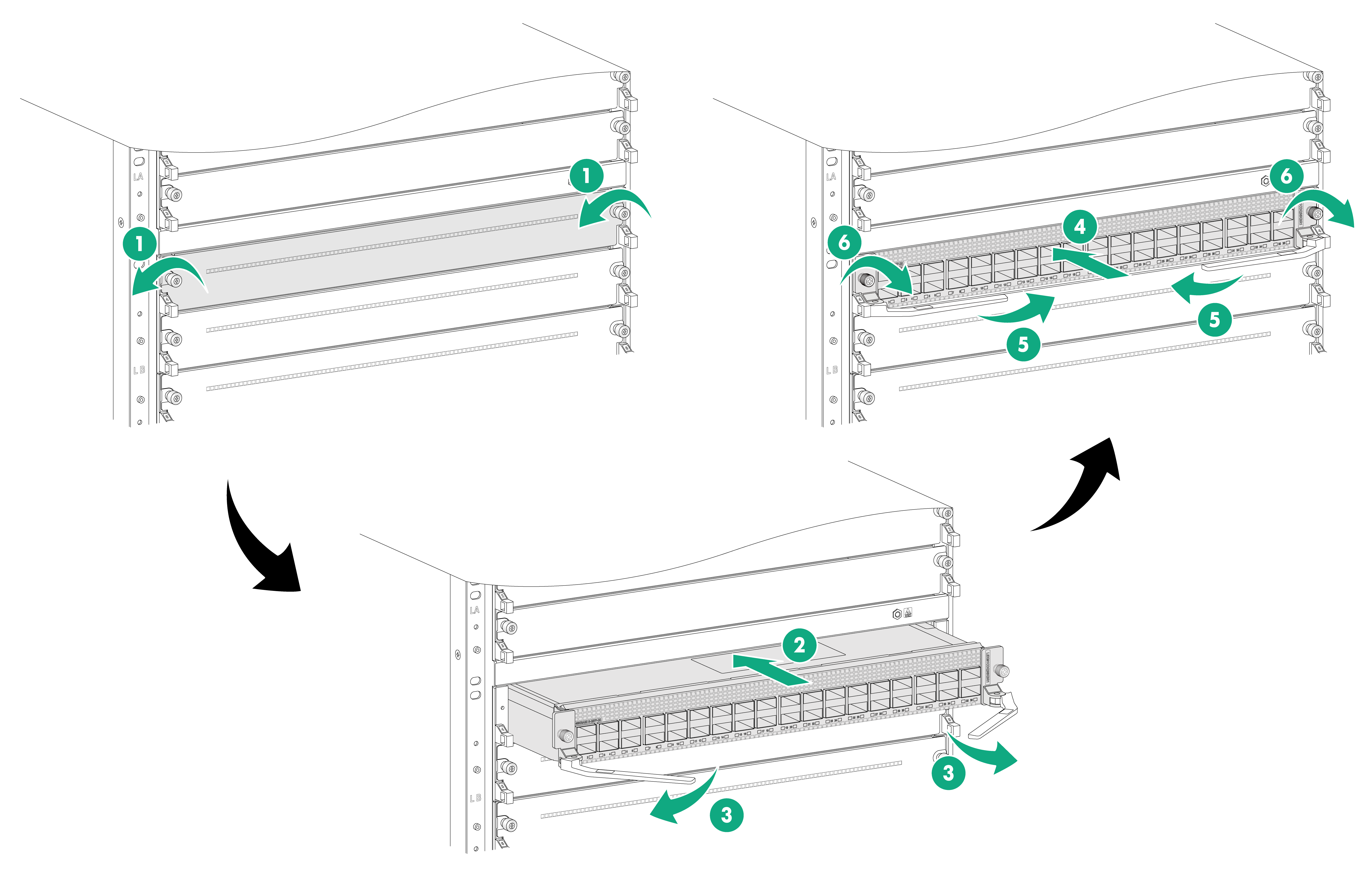
To install a service module:
1. As shown by callout 1 in Figure 3, remove the filler panel from the target interface module slot.
Keep the removed filler panel secure for future use.
2. As shown by callout 2 in Figure 3, holding the two sides of the interface module firmly, push it slowly and steadily into the slot along the guide rails..
3. As shown by callout 3 in Figure 3, pull the ejector levers of the service module outward when most part of the service module is inserted in the slot.
4. Push the service module until the brakes on its ejector levers touch the slot edges tightly.
5. As shown by callout 4 in Figure 3, continue to push the service module by its middle part on the front panel until you cannot push it further.
6. As shown by callout 5 in Figure 3, push the ejector levers inward until they come in close contact with the front panel.
7. As shown by callout 6 in Figure 3, fasten the captive screws on the service module. As a best practice, fasten each captive screw to a torque of 5 kgf-cm (0.49 Nm).
Figure 3 Installing an interface module (S12516CR)
Installing fabric modules
Restrictions and guidelines
· To avoid module damage and ensure correct module operation, make sure the fabric module model matches the SEU, interface module, and environment management module models.
¡ Type K fabric modules can operate together only with Type K SEUs and Type K interface modules. Type K SEUs have a character of K in their identifiers, for example, LSXM1SUPKR1. Type K interface modules have a character of K in their identifiers, for example, LSXM1CGQ48KBR1.
¡ Type S fabric modules can operate together only with Type S SEUs, Type S interface modules, and Type S environment management modules. Type S SEUs have a character of S in their identifiers, for example, LSXM1SUPRS2. Type S environment management modules have a character of S in their identifiers, for example, LSXM1CMURS2. Type S interface modules have a character of S in their identifiers, for example, LSXM3TGS48SF2.
· When you install a fabric module, avoid damaging the connectors on it.
· You can install a maximum of six Type S fabric modules (for example, LSXM3SFS08F2) on the device if Type S fabric modules are used on the device. For an S12508CR switch router, you can install Type S fabric modules only in slots 14 to 19. For an S12516CR switch router, you can install Type S fabric modules only in slots 22 to 27. You are not required to install filler panels in the other fabric module slots.
· Slots 20, 21, and 28 on an S12516CR and slots 12, 13, 20 on an S12508CR can be empty without a fabric module or filler panel installed. The other fabric module slots must have a fabric module or filler panel installed.
· To use S12500R interface modules on an S12516CR, install fabric modules in slots 22 to 27. To use S12500R interface modules on an S12508CR, install fabric modules in slots 14 to 19. The S12500R interface modules cannot start up if no fabric modules are installed in the six slots.
· Before installing a fan tray, install fabric modules or filler panels in the fabric module slots that the fan tray will cover. For fabric module slots covered by fan tray slots, see Table 1.
Table 1 Fabric module slots covered by fan tray slots
|
Fan tray slot |
FAN1 |
FAN2 |
FAN3 |
FAN4 |
FAN5 |
||||
|
S12508CR fabric module slot |
12 |
13 |
14 |
15 |
16 |
17 |
18 |
19 |
20 |
|
S12516CR fabric module slot |
20 |
21 |
22 |
23 |
24 |
25 |
26 |
27 |
28 |
· To replace or install a fabric module for an operating device, first remove the fan tray that covers the slot of the fabric module. Install the fan tray immediately after the replacement or installation. You can replace another fan tray only after this fan tray is operating correctly.
· The device comes with empty fabric module slots. Prepare appropriate type and number of fabric module for the device as required.
Procedure
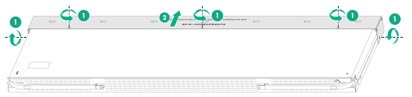
1. Remove the protection box from the connector side of the fabric module. See Figure 4.
2. Press the spring clip on each ejector lever of the fabric module to release the ejector levers.
3. Orient the fabric module with the side marked "Up" facing upwards. Hold the fabric module front panel near the ejector levers with one hand and support the module bottom with the other. Place the module bottom on the guide rails at the chassis bottom. Align the fabric module with the target slot and insert it into the slot along the guide rails. See callout 1 in Figure 5.
Keep the module parallel to the slot to avoid touching other components in the chassis.
4. As shown by callout 2 in Figure 5, continue to push the fabric module until the brakes on its ejector levers touch the slot edges tightly. Simultaneously rotate the ejector levers inward until the spring clips lock the ejector levers in place and the fabric module is completely seated in the slot.
Figure 4 Removing the protection box from the fabric module (S12516CR fabric module)
|
(1) Loosen the captive screws that secure the protection box to the fabric module |
|
(3) Hold two sides of the protection box to disengage it from the connector side of the fabric module |
Figure 5 Installing a fabric module (S12516CR)
If a fabric module has an air baffle, make sure the baffle is closed before installing the fabric module. After removing the fabric module, close the baffle.
Figure 6 Fabric module with an air baffle
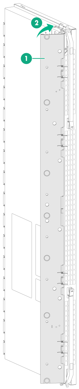
|
(1) Air baffle |
(2) Close the air baffle until the latch locks it in place |
Installing a filler panel in a fabric module slot
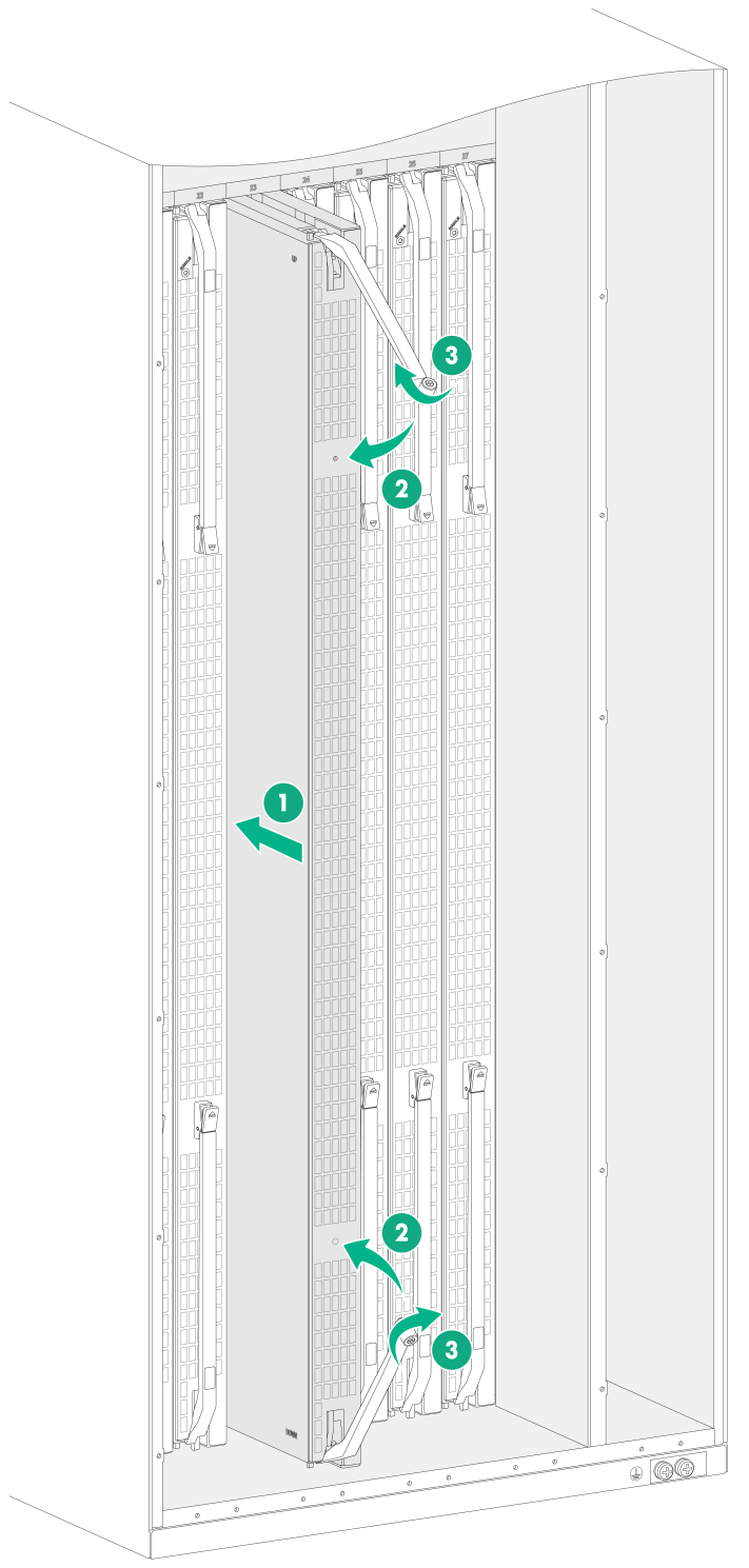
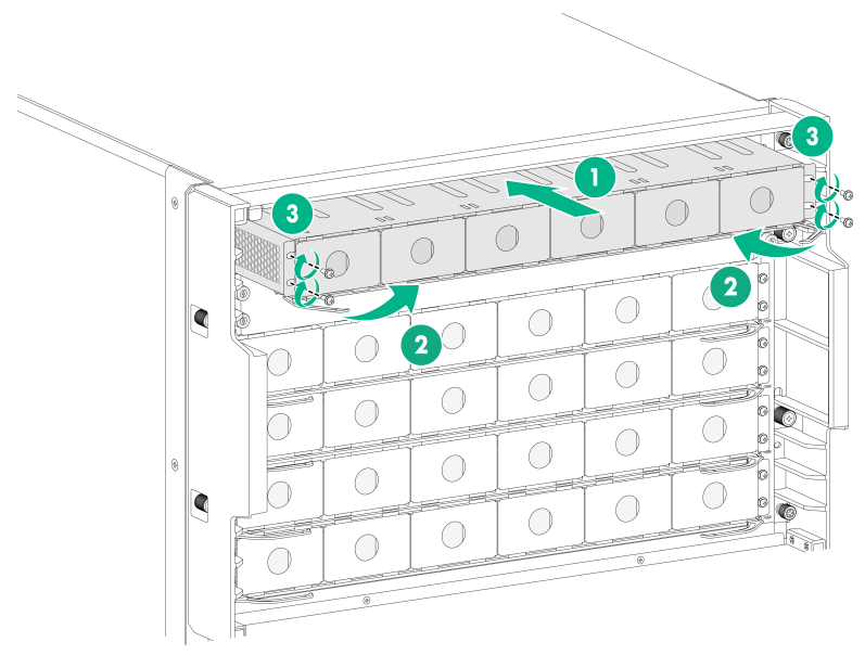
1. Loosen the captive screws on the ejector levers and rotate outward the ejector levers.
2. Orient the filler panel with the side marked "Up" facing upwards. Hold the filler panel front panel near the ejector levers with one hand and support its bottom with the other. Place the filler panel bottom gently on guide rails at the chassis bottom. Align the filler panel with the fabric module slot. Push the filler panel slowly into the slot along the guide rails. See callout 1 in Figure 7.
Keep the filler panel parallel to the fabric module slot to avoid touching other components in the chassis.
3. As shown by callout 2 in Figure 7, continue to push the filler panel until the brakes on its ejector levers touch the slot edges tightly. Simultaneously rotate the ejector levers inward.
4. As shown by callout 3 in Figure 7, fasten the captive screws on the ejector levers.
Figure 7 Installing a filler panel in a fabric module slot (S12516CR)
Removing a filler panel from a fabric module slot
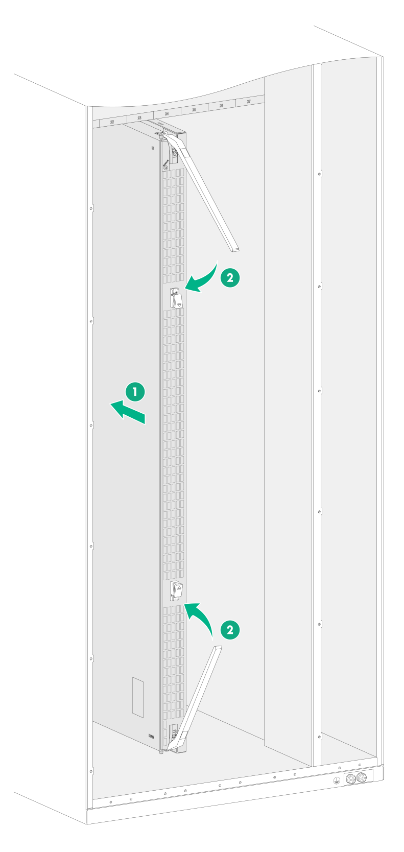
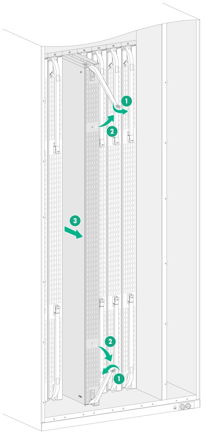
1. As shown by callout 1 in Figure 8, loosen the captive screws on the ejector levers.
As a best practice, use a torque of 5 kgf-cm (0.49 Nm) to loosen the captive screws.
2. As shown by callout 2 in Figure 8, rotate outward the ejector levers. Then pull the filler panel part way out of the slot.
3. As shown by callout 3 in Figure 8, hold the filler panel by the top and bottom edges to pull the filler panel out of the slot.
Keep the removed the filler panel secure for future use.
Figure 8 Removing the filler panel from a fabric module slot (S12516CR)
Installing fan trays
|
|
WARNING! · When installing or removing a fan tray, ensure electricity safety and avoid being injured by the rotating fan blades. · When you hot-swap a fan tray, the remaining fan tray automatically increases the rotation speed and makes louder noise. Take protection measures such as wearing an earmuff or earplug and make good preparations in advance to ensure that the operation time is as short as possible. |
|
|
CAUTION: · To avoid fan tray damage, use both hands when installing or removing a fan tray. · To prevent dust and ensure adequate heat dissipation, keep the old fan tray in the chassis until a new fan tray is ready to be installed. As a best practice, finish replacing a fan tray within 3 minutes. |
|
|
CAUTION: · The device comes with the FAN1 and FAN5 slots installed with filler panels and the FAN2 to FAN4 slots empty. The maximum number of fan trays depends on the type of modules installed on the device. The device supports a maximum of three fan trays when using Type S modules. To ensure adequate heat dissipation when using Type S modules on the device, install three fan trays in slots FAN2 to FAN 4 and keep the filler panels in slots FAN 1 and FAN 5 in position. To use other types of modules on the device, install a fan tray in each of the five fan tray slots. · Before installing a fan tray in the FAN1 or FAN5 slot, remove the filler panel from the slot. |
|
|
IMPORTANT: A fan tray covers fabric module slots. Install fabric modules or filler panels in the fabric module slots before installing a fan tray. · If a fabric module is installed in a fabric module slot, make sure the spring clips lock the ejector levers of the fabric module in place. · If a fabric module filler panel is installed in a fabric module slot, make sure the ejector levers of the fabric module filler panel are secured in place by captive screws. |
|
|
IMPORTANT: As a best practice, fasten a captive screw to a torque of 5 kgf-cm (0.49 Nm). |
Installing a fan tray
The following procedure installs a fan tray in the FAN2 slot on an S12516CR.
To install a fan tray:
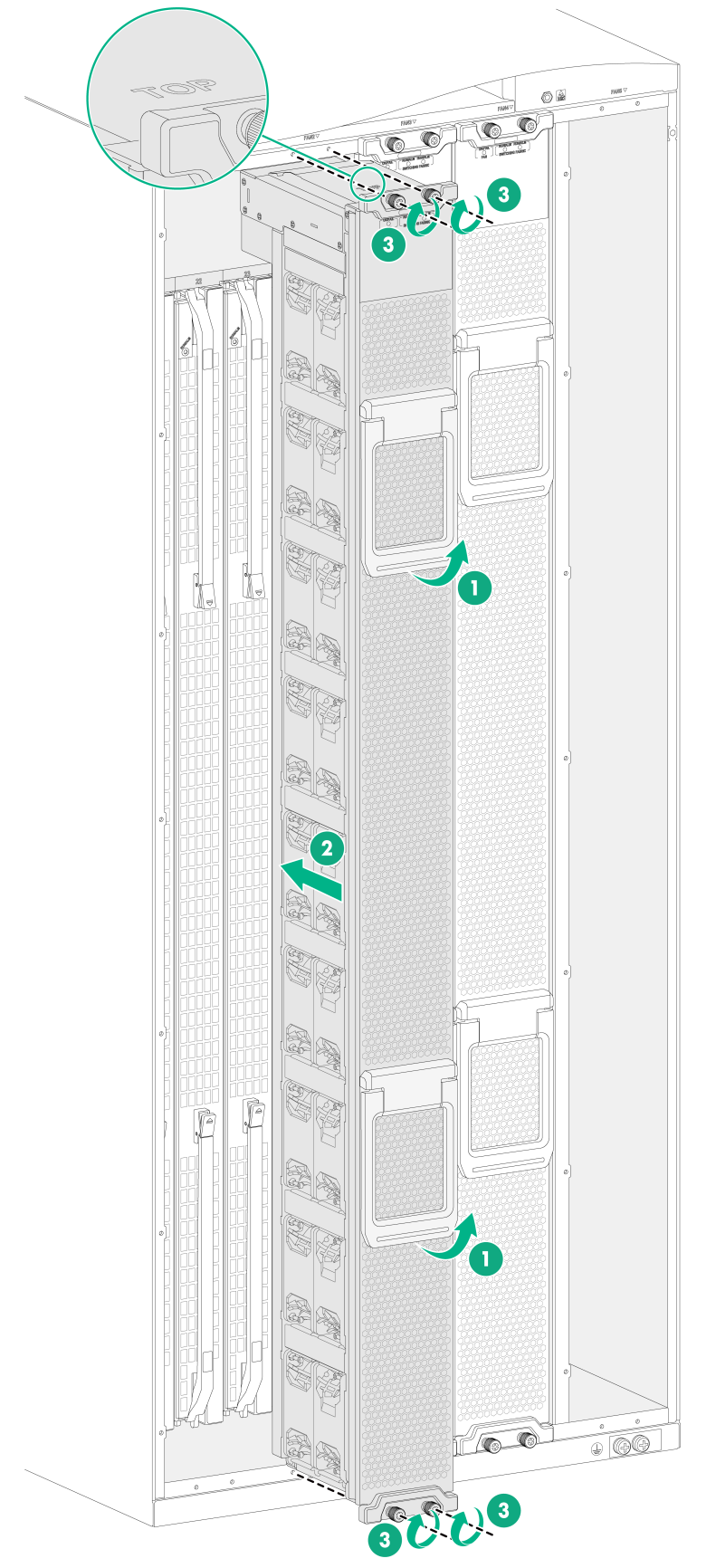
1. As shown by callout 1 in Figure 9, orient the fan tray with the side marked "TOP" facing upwards and pivot up the fan tray handles to make them perpendicular to the fan tray.
2. As shown by callout 2 in Figure 9, hold the fan tray handles and slide the fan tray along the guide rails into the slot.
3. As shown by callout 3 in Figure 9, fasten the captive screws on the fan tray.
4. Pivot down the fan tray handles to be sure that they hold firmly on the fan tray.
Figure 9 Installing a fan tray (S12516CR)
Removing the filler panel from a fan tray slot
The device comes with the FAN1 and FAN5 slots installed with filler panels. To install a fan tray in the FAN1 or FAN5 slot or install a fabric module behind the FAN 1 or FAN 5 slot, first remove the filler panel from the slot. The following procedure removes the filler panel from the FAN1 slot.
To remove the filler panel from a fan tray slot:
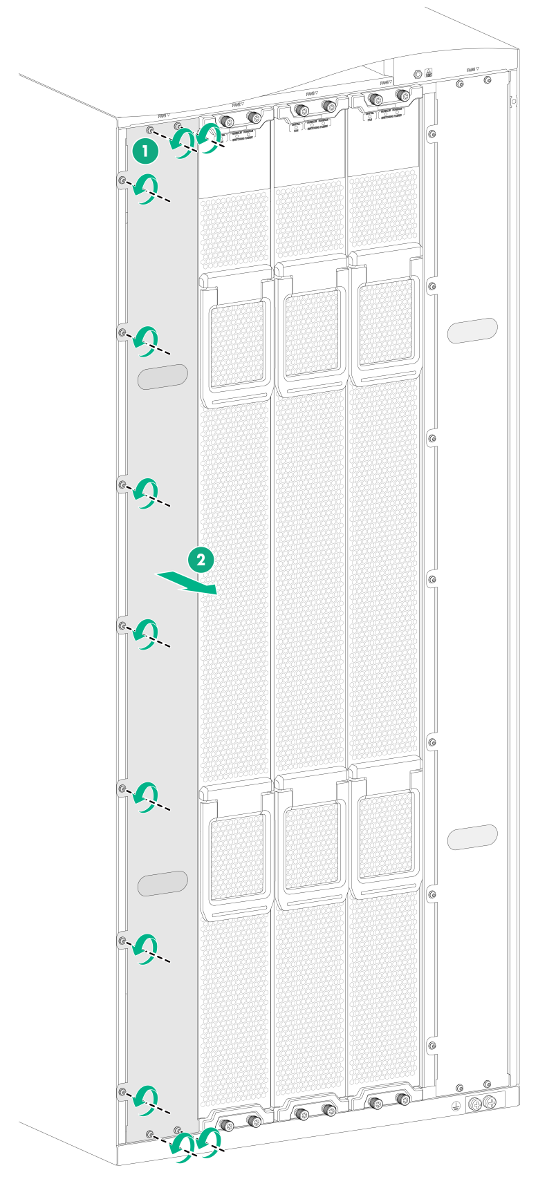
1. As shown by callout 1 in Figure 10, loosen the M3 screws on the fan tray filler panel.
2. As shown by callout 2 in Figure 10, put your fingers into the holes of the filler panel, and then pull the filler panel out.
Keep the removed filler panel secure for future use.
Figure 10 Removing the filler panel from a fan tray slot (S12516CR)
Installing power supplies and power trays
Power trays and power supplies
|
|
CAUTION: · Do not install power trays of different models on the same device. · For the compatibility between the power supplies and power trays, see H3C S12500R Switch Router Series Hardware Information and Specifications. |
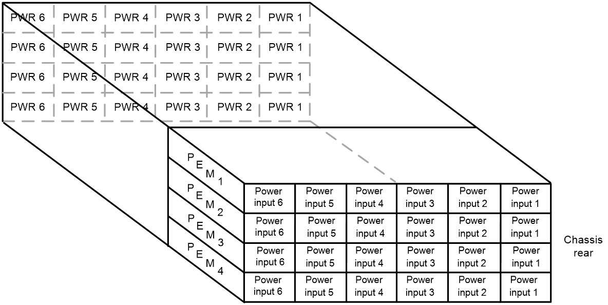
The power supplies are installed in the power trays. Power supplies at the front correspond to the power input ends at the rear as shown in Figure 11 and Figure 12.
"PEM" in these two figures refer to power tray.
Figure 11 Power supplies and power input ends on the S12516CR
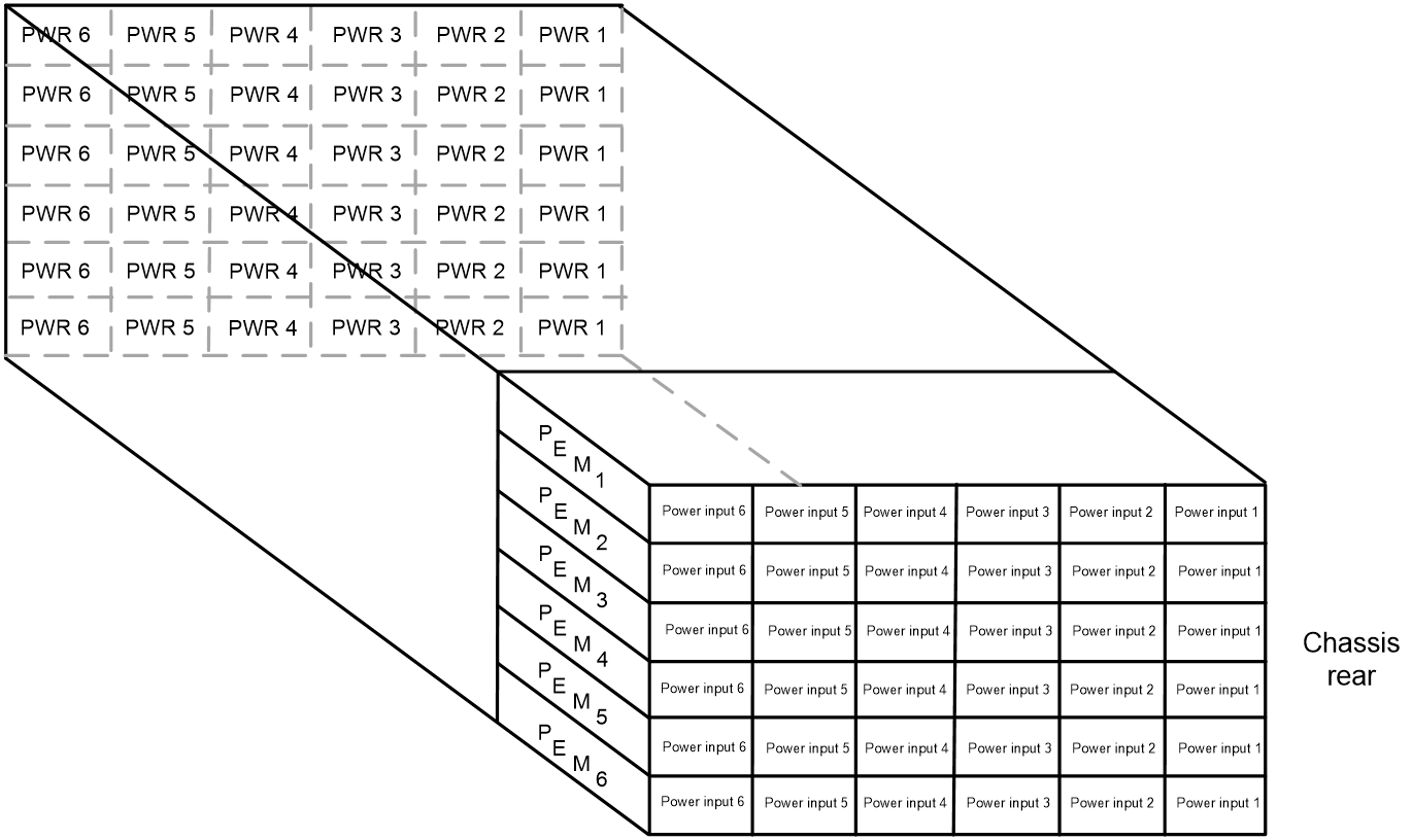
Figure 12 Power supplies and power input ends on the S12508CR
Installing a power supply
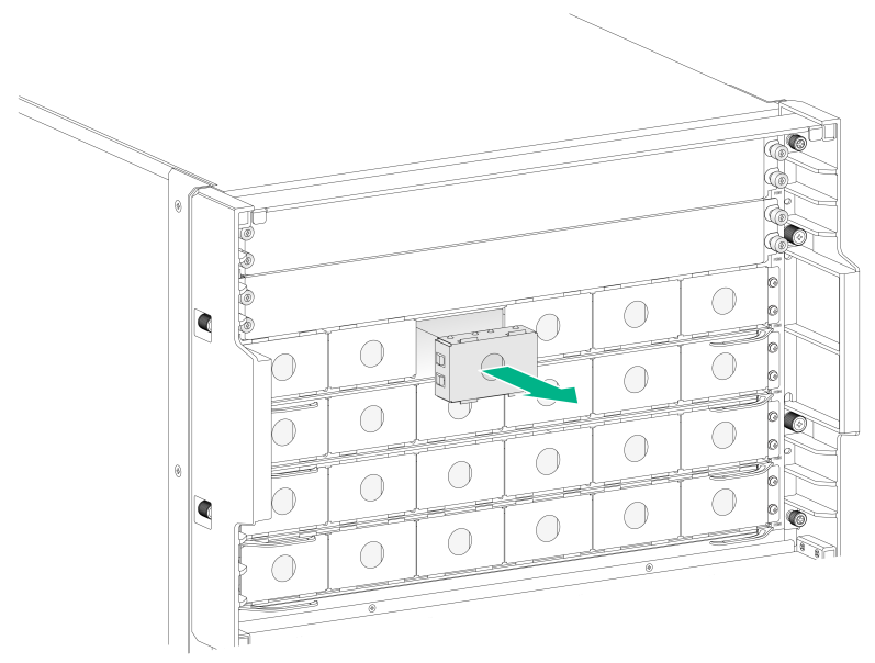
1. Remove the filler panel from the target power supply slot.
Put your forefinger into the hole of the filler panel to hold and pull out the filler panel along the guide rails, as shown in Figure 13.
Figure 13 Removing a filler panel (S12516CR)
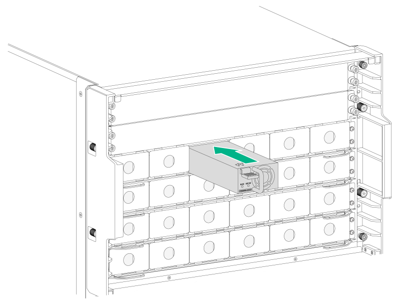
2. Align the power supply with the power supply slot. Then slide the power supply along the guide rails into the slot until the latch locks the power supply in place, as shown in Figure 14.
Figure 14 Installing a power supply (S12516CR)
Connecting power cords
|
|
WARNING! · Make sure each power cord has a separate circuit breaker. · Before connecting a power cord, make sure the circuit breaker at the power input end of the power cord and the two power switches on the device are both turned off. |
Connecting an AC power cord
1. Remove the protective plate over the power input area.
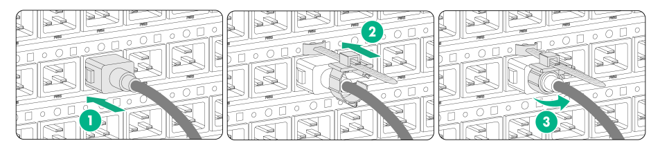
2. Connect the AC power cord connector to the AC input receptacle on the power tray, as shown by callout 1 in Figure 15.
3. Attach a cable clamp to the power tray. Release the tab on the tie mount and then slide the cable clamp forward until it is flush against the edge of the connector, as shown by callout 2 in Figure 15.
4. Close the cable clamp, as shown by callout 3 in Figure 15.
5. Connect the other end of the AC power cord to an AC power source.
Figure 15 Connecting an AC power cord
Connecting a DC power cord
1. Remove the protective plate over the power input area.
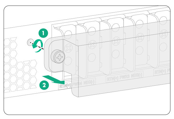
2. Remove the cover on the power tray, as shown in Figure 16.
Keep the removed cover secure and reinstall it after connecting the power cord.
Figure 16 Removing the cover from the power tray
3. Remove the screws on the terminal blocks.
4. Use the screws to connect the black wires to the positive terminals marked with RTN(+) and the blue wires to the negative terminals marked with NEG(–), as shown in Figure 17.
Figure 17 Connecting DC power cords to the DC terminal blocks
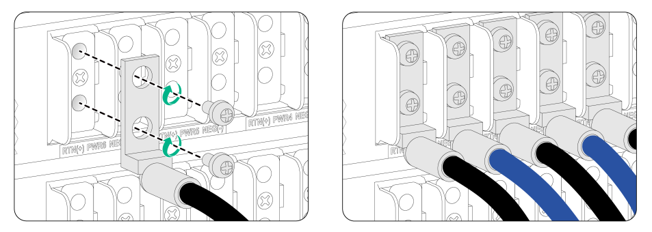
5. Connect the other end of the power cord to a DC power source.
Connect the blue wires to the negative terminals marked with –48V and the black wires to the positive terminals marked with RTN(+).
6. Reinstall the cover on the power tray and then use a Phillips screwdriver to fasten the captive screws.
(Optional) Installing power trays
The device comes with power trays installed. You can install more power trays on it.
To install a power tray:
1. As shown in Figure 18 and Figure 19, remove the front and rear filler panels from the target power tray slot.
2. As shown by callout 1 in Figure 20, hold both sides of the power tray with two hands, and insert the power tray into the slot along the guide rails slowly and steadily.
3. As shown by callout 2 in Figure 20, close the ejector levers when the ejector levers touch the slot edges tightly.
4. As shown by callout 3 in Figure 20, use a screwdriver to fasten the screws on the power tray.
As a best practice, use a torque of 5 kgf-cm (0.49 Nm) to fasten the screws.
Figure 18 Removing a front filler panel from a power tray slot (S12516CR)
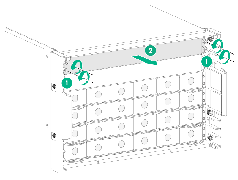
Figure 19 Removing a rear filler panel from a power tray slot (S12516CR)
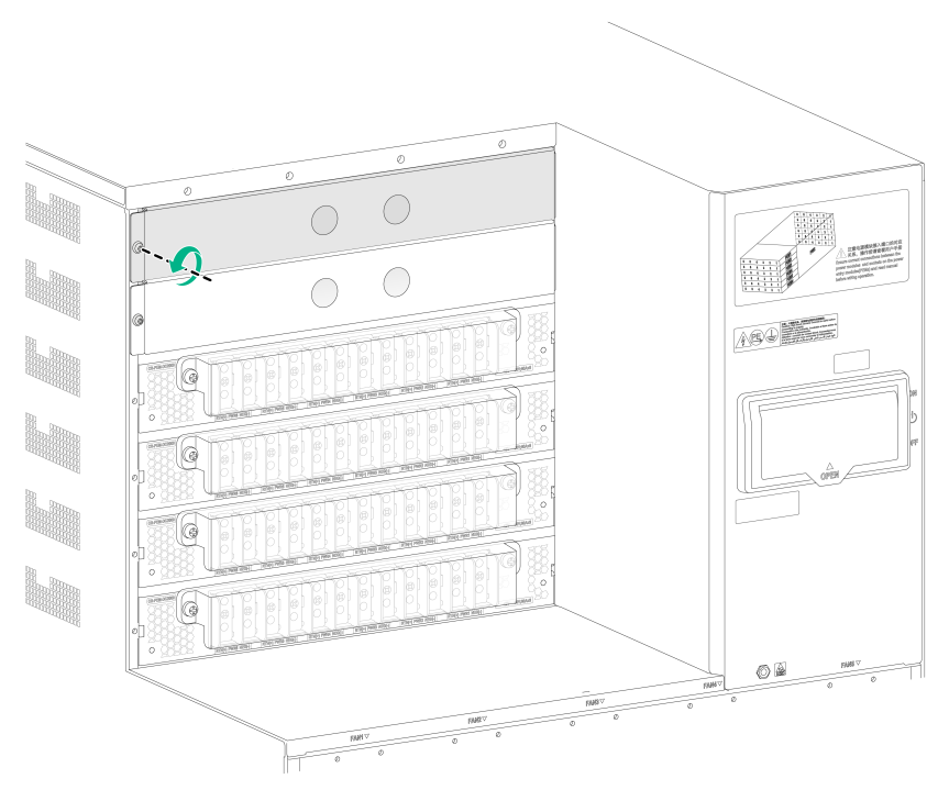
Figure 20 Installing a power tray (S12516CR)
Installing the air filter in the top hood
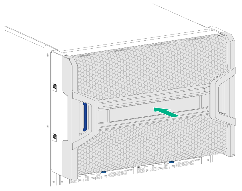
The device comes with the top hood installed. You only need to install the air filter in the top hood.
To install the air filter in the top hood:
1. Unpack the air filter.
2. Position the air filter over the top hood, and then push the air filter until it is seated into the top hood.
Figure 21 Air filter and top hood
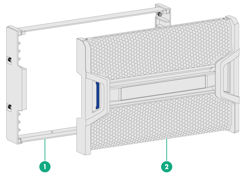
|
(1) Top hood |
(2) Air filter |
Figure 22 Installing the air filter in the top hood
Installing transceiver modules
|
|
CAUTION: If you are not to use a fiber port or transceiver module, insert dust plugs into the port or module. If you are not to connect an optical fiber, install dust caps for the fiber connector. |
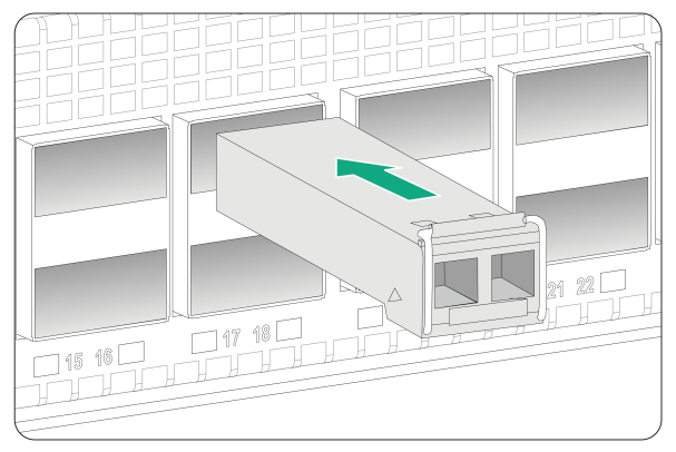
Installing a transceiver module
The transceiver modules are hot swappable.
To install a transceiver module:
1. Unpack the transceiver module.
Do not touch the golden plating of the transceiver module.
2. Pivot the clasp of the module up. Holding the transceiver module, gently push the transceiver module into the slot until it has firm contact with the slot, as shown in Figure 23.
Figure 23 Installing a transceiver module
|
|
NOTE: The types of transceiver modules supported by the device might change over time. For information about installing a transceiver module, see H3C Transceiver Modules and Network Cables Installation Guide. |
Connecting an interface cable
|
|
CAUTION: When you connect an interface cable, make sure the bend radius of the interface cable is no less than eight times the cable diameter. |
The interface cables are hot swappable.
To connect an interface cable:
1. Unpack the interface cable.
2. Correctly orient the interface cable connector and gently insert the connector into the target port. To be sure that the connector is seated securely in the port.
Transceiver modules and fiber ports have disorientation rejection designs. If you cannot insert a transceiver module easily into a port, the orientation might be wrong. Remove and reorient the transceiver module.
