- Table of Contents
-
- H3C Campus Fixed-Port Switches Web-Based Quick Start Configuration Guide-6W100
- 01-Compatible Product Models
- 02-Configuring Web Login with the Default IP
- 03-Web Login to a Device Without a Default IP
- 04-Interface Settings
- 05-PoE
- 06-VLAN
- 07-DHCP Server
- 08-DHCP Relay Agent
- 09-Static Routing
- 10-Policy-Based Routing
- 11-Ethernet Link Aggregation
- 12-Port Mirroring
- 13-Packet Filtering
- 14-Interface Rate Limit
- 15-Traffic Constrain
- 16-Spanning Tree
- 17-Direct Portal Authentication
- 18-Port Security
- 19-Port Isolation
- 20-ARP Attack Protection
- 21-Configuring a Static ARP Entry
- 22-IGMP Snooping
- 23-Enabling IPSG on an Interface
- 24-Software Upgrade
- 25-Adding Administrator Accounts
- 26-Ping and Tracert
- 27-Password Change
- 28-System Time
- 29-System Log
- 30-Configuration Backup, Export, Restoration to Factory Default
- 31-Device Reboot
- 32-Small-Sized Campus Network Configuration Guide
- Related Documents
-
| Title | Size | Download |
|---|---|---|
| 17-Direct Portal Authentication | 846.71 KB |
Direct Portal Authentication Quick Start Configuration Guide
Network configuration
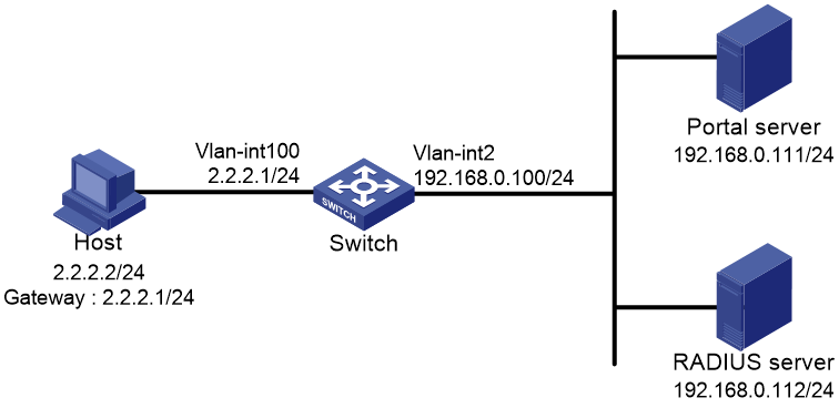
As shown in Figure 1, a host is directly connected to the switch (the access device).
· Assign a public IP address to the host either manually or through DHCP.
· Configure direct portal authentication on the switch, so the host can access only the portal Web server before passing the authentication and can access other network resources after passing the authentication.
· Use a portal server as both a portal authentication server and a portal Web server.
· Use a RADIUS server as the authentication and accounting server.
Procedures
Configuring the portal server
Details not shown.
Configuring the switch
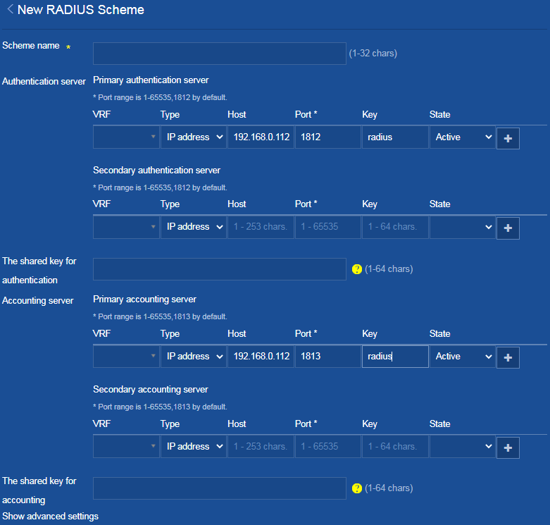
1. Configure a RADIUS scheme:
a. From the left navigation pane, select Security > Authentication > RADIUS.
b. Click the Add icon ![]() at the upper right of the page to add a RADIUS scheme.
at the upper right of the page to add a RADIUS scheme.
c. Set the scheme name to rs1.
d. Configure the primary authentication server.
Set its IP address to 192.168.0.112, port number to 1812, and shared key to radius. Set its
state to Active, and then click the Add icon ![]() next to it to add the primary authentication server.
next to it to add the primary authentication server.
e. Configure the primary accounting server. Set
its IP address to 192.168.0.112,
port number to 1813, and shared key to radius. Set its state to Active,
and then click the Add icon ![]() next to it to add the primary accounting server.
next to it to add the primary accounting server.
Figure 2 Adding a RADIUS scheme
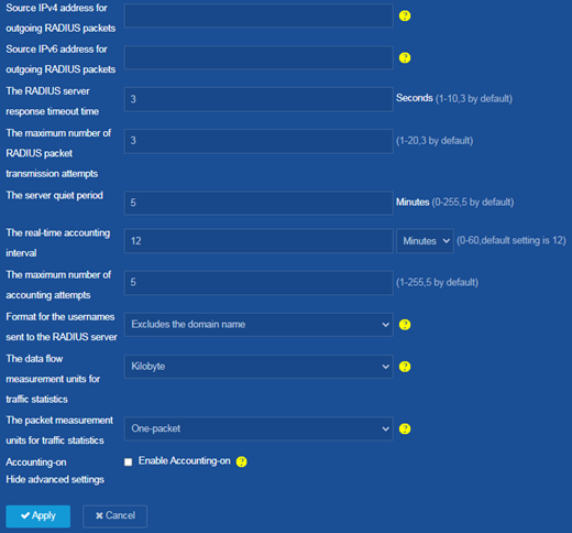
f. Click Show advanced settings.
g. Select Excludes the domain name from the Format for the usernames sent to the RADIUS server list.
h. Click Apply.
The system displays a success message after it adds the RADIUS scheme.
Figure 3 Adding a RADIUS scheme
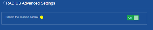
i. Click the Settings icon ![]() at the upper right of the RADIUS
configuration page to enter the
RADIUS Advanced Settings page.
at the upper right of the RADIUS
configuration page to enter the
RADIUS Advanced Settings page.
j. Enable the session control function.
Figure 4 Enabling RADIUS session control
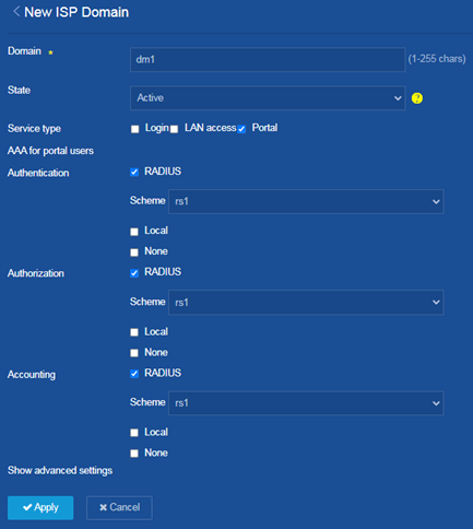
2. Configure an ISP domain:
a. From the left navigation pane, select Security > Authentication > ISP Domains.
b. Click the Add icon ![]() at the upper right of the page to add an ISP domain.
at the upper right of the page to add an ISP domain.
c. Set the domain name to dm1 and set its state to Active.
d. Set the service type to Portal.
e. Select RADIUS for authentication, authorization, and accounting and select the rs1 RADIUS scheme as the scheme for each of them.
f. Click Apply.
The system displays a success message after it adds the ISP domain.
Figure 5 Adding an ISP domain
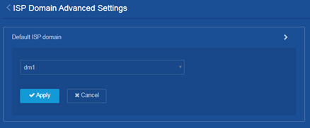
g. Click the Settings icon ![]() at the upper right of the ISP domain
configuration page to enter the
ISP Domain Advanced Settings page. Specify domain dm1
as the default ISP domain.
at the upper right of the ISP domain
configuration page to enter the
ISP Domain Advanced Settings page. Specify domain dm1
as the default ISP domain.
If a user enters the username without the ISP domain name at login, the authentication and accounting methods of the default domain are used for the user.
h. Click Apply.
The system displays a success message after the configuration.
Figure 6 Configuring advanced settings for the ISP Domain
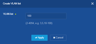
3. Configure VLANs and VLAN interfaces:
a. From the left navigation pane, select Network > Links > VLAN.
b. Click the Add
icon ![]() at the upper right of the page to create VLAN 100.
at the upper right of the page to create VLAN 100.
c. Enter 100 in the VLAN list field.
d. Click Apply.
The system displays a success message after it adds the VLAN.
Figure 7 Creating VLAN 100
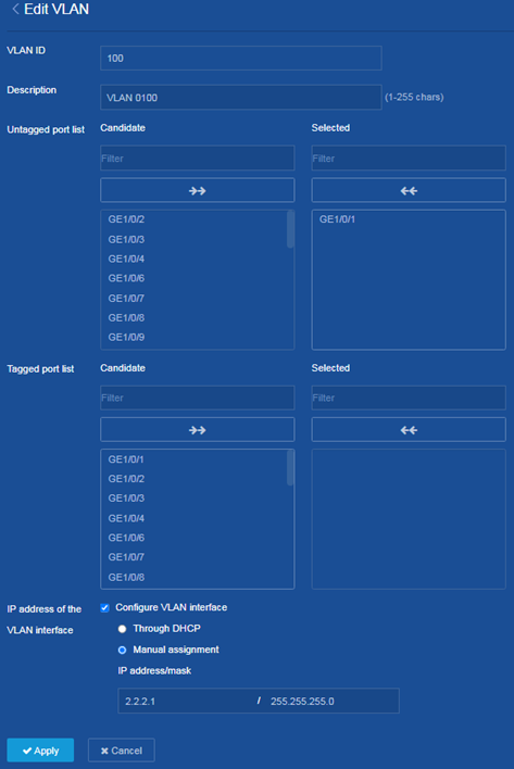
e. Click the ![]() icon to enter the Edit
VLAN page.
icon to enter the Edit
VLAN page.
f. Assign GE1/0/1 to the untagged port list of VLAN 100.
g. Select Configure VLAN interface for the IP address of the VLAN interface field. Select Manual assignment. Specify the IP address of the VLAN interface as 2.2.2.1. Specify the mask as 255.255.255.0.
h. Click Apply.
The system displays a success message after the configuration.
Figure 8 Editing VLAN 100
i. Configure VLAN 2 and its VLAN interface in the same way VLAN 100 and its VLAN interface are configured. (Details not shown.).
4. Configure portal authentication:
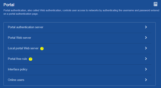
a. From the left navigation pane, select Security > Access Control > Portal enter the portal configuration page.
Figure 9 Portal configuration page
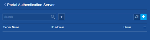
b. Click the ![]() icon on the right
side of Portal authentication
server to enter the Portal Authentication Server page.
icon on the right
side of Portal authentication
server to enter the Portal Authentication Server page.
Figure 10 Portal authentication server page
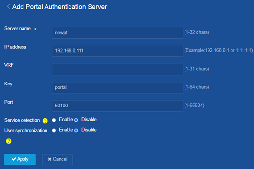
c. Click the Add icon ![]() at the upper right of the page to add a portal authentication server.
at the upper right of the page to add a portal authentication server.
d. Set the server name as newpt. Specify its IP address as 192.168.0.111, the shared key as portal, and port number to 50100.
e. Click Apply.
The system displays a success message after the configuration.
Figure 11 Adding a portal authentication server
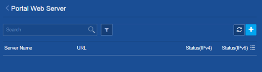
f. Return back to the portal configuration page.
Figure 12 Portal configuration page

g. Click the ![]() icon on the right
side of Portal Web server to enter the Portal Web
Server page.
icon on the right
side of Portal Web server to enter the Portal Web
Server page.
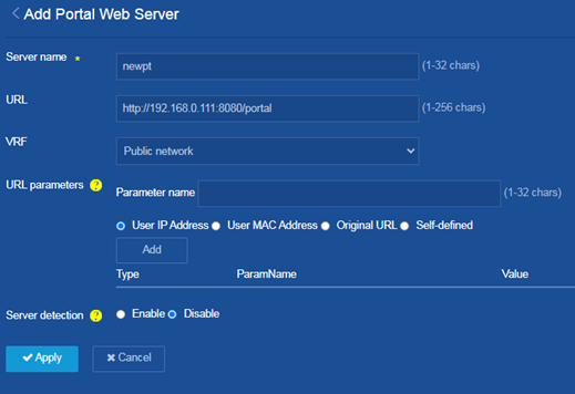
Figure 13 Portal web server page
h. Click the Add icon ![]() at the upper right of the page to add a portal Web server.
at the upper right of the page to add a portal Web server.
i. Set the server name as newpt. Specify the URL as http://192.168.0.111:8080/portal. (Configure the actual portal Web server URL used. The URL in the following figure is for illustration only.)
j. Click Apply.
The system displays a success message after the configuration.
Figure 14 Adding a portal Web server
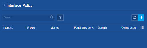
k. Return back to the portal configuration page.
Figure 15 Portal configuration page
l. Click the ![]() icon on the right
side of Interface policy to
enter the Interface Policy page.
icon on the right
side of Interface policy to
enter the Interface Policy page.
Figure 16 Interface policy page
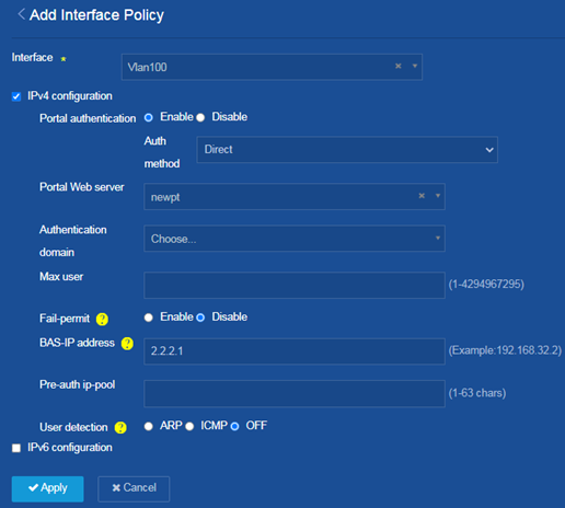
m. Click the Add icon ![]() at the upper right of the page to add an
interface policy.
at the upper right of the page to add an
interface policy.
n. Select interface Vlan100. Select IPv4 configuration and enable portal authentication. Use the direct authentication method. Apply portal Web server newpt and specify the BAS-IP address as 2.2.2.1.
o. Click Apply.
The system displays a success message after the configuration.
Figure 17 Adding an interface policy
5. Save the configuration:
Click the Save icon ![]() at the upper left of the page.
at the upper left of the page.
Configuring the RADIUS server
Add user accounts on the RADIUS server and make sure it can provide authentication, authorization, and accounting services.
For more information about configuring user accounts on the RADIUS server, see the user guide for the RADIUS server.
Verifying the configuration
1. On the Security > Authentication > RADIUS page, verify that the rs1 RADIUS scheme has been added correctly.
2. On the Security > Authentication > ISP Domains page, verify that the dm1 ISP domain has been added correctly.
3. After the portal user comes online, access the Security > Access Control > Portal page to verify that the number of users on interface Vlan100 is 1.
