- Table of Contents
-
- H3C Campus Fixed-Port Switches Web-Based Quick Start Configuration Guide-6W100
- 01-Compatible Product Models
- 02-Configuring Web Login with the Default IP
- 03-Web Login to a Device Without a Default IP
- 04-Interface Settings
- 05-PoE
- 06-VLAN
- 07-DHCP Server
- 08-DHCP Relay Agent
- 09-Static Routing
- 10-Policy-Based Routing
- 11-Ethernet Link Aggregation
- 12-Port Mirroring
- 13-Packet Filtering
- 14-Interface Rate Limit
- 15-Traffic Constrain
- 16-Spanning Tree
- 17-Direct Portal Authentication
- 18-Port Security
- 19-Port Isolation
- 20-ARP Attack Protection
- 21-Configuring a Static ARP Entry
- 22-IGMP Snooping
- 23-Enabling IPSG on an Interface
- 24-Software Upgrade
- 25-Adding Administrator Accounts
- 26-Ping and Tracert
- 27-Password Change
- 28-System Time
- 29-System Log
- 30-Configuration Backup, Export, Restoration to Factory Default
- 31-Device Reboot
- 32-Small-Sized Campus Network Configuration Guide
- Related Documents
-
| Title | Size | Download |
|---|---|---|
| 08-DHCP Relay Agent | 466.24 KB |
DHCP Relay Agent Quick Start Configuration Guide
Network configuration
As shown in Figure 1, the DHCP client runs on subnet 10.10.1.0/24 and the IP address of the DHCP server is 10.1.1.1/24. By default, the client cannot obtain IP addresses from the DHCP server, because they do not run on the same subnet. Configure a DHCP relay agent on subnet 10.10.1.0/24, so the DHCP server can assign IP addresses from subnet 10.10.1.0/24 and assign related network settings to the client.

Procedure
Configure DHCP server (Switch C)
1. Configure VLAN.
a. From the left navigation pane, select Network > Links > VLAN.
b. On the page that opens, click the create icon ![]() to
create VLAN 20.
to
create VLAN 20.
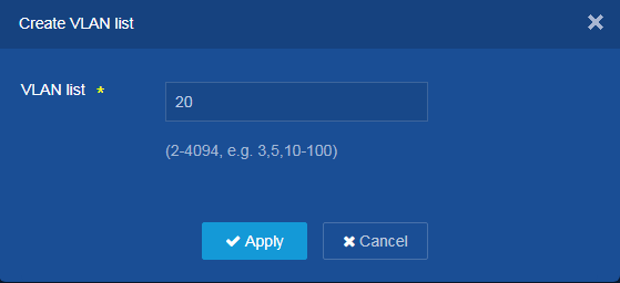
c. Add VLAN 20 to the VLAN list, and then click Apply.
Figure 2 Creating VLAN 20
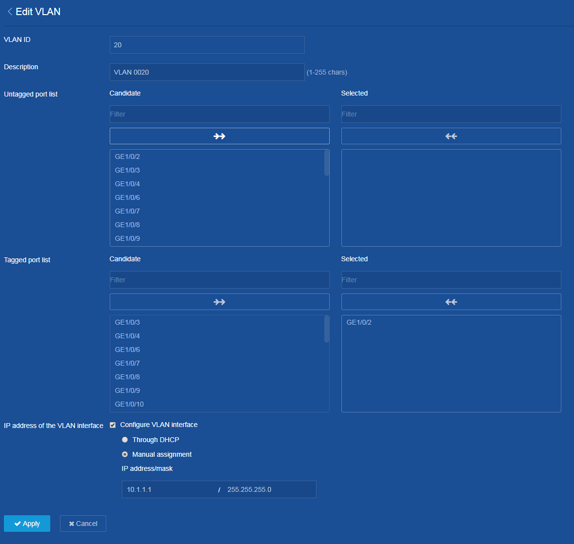
d. Click the edit icon ![]() on the right of VLAN 20 to edit the settings of VLAN 20.
on the right of VLAN 20 to edit the settings of VLAN 20.
e. Add GE1/0/2 to the tagged port list of VLAN 20.
f. Select Configure VLAN interface at the IP address of the VLAN interface parameter.
g. Assign IP address 10.1.1.1/24 to VLAN-interface 20.
h. Click Apply.
The system displays a success message if you configure VLAN 20 successfully.
Figure 3 Configuring VLAN 20
2. Configure static routes.
a. From the left navigation pane, select Network > Routing > Static Routing.
b. On the page that opens, click the ![]() icon on the right of IPv4 Static Routes.
icon on the right of IPv4 Static Routes.
c. Click the add icon ![]() to add an IPv4 static
route.
to add an IPv4 static
route.
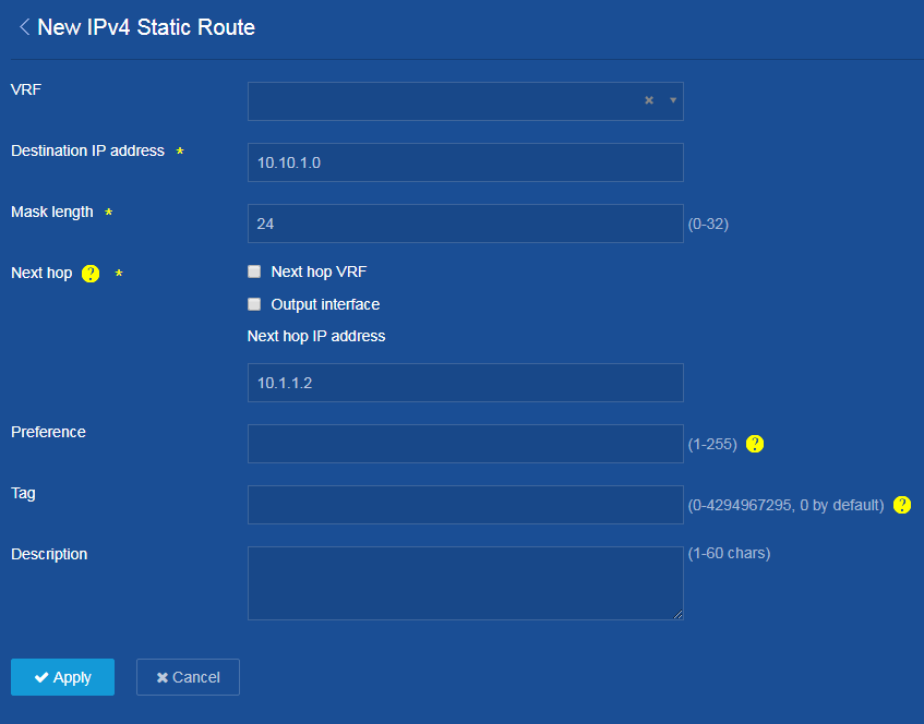
d. Configure 10.10.1.0/24 as the destination and 10.1.1.2 as the next hop. Do not select Output interface at the Next hop parameter.
e. Configure other parameters as needed, and then click Apply.
Figure 4 Adding IPv4 static route
3. Create DHCP server.
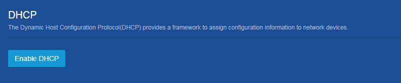
a. From the left navigation pane, select Network > Service > DHCP.
b. On the page that opens, click Enable DHCP.
Figure 5 Enabling DHCP
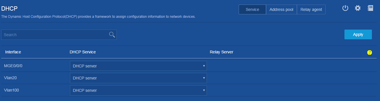
c. Click Service at the upper right of the DHCP configuration page, and then set the DHCP service type to DHCP server for VLAN-interface 20. By default, an interface operates in DHCP server mode.
Figure 6 Configuring DHCP server mode
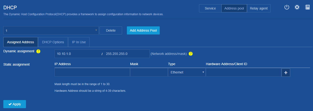
d. Click Address pool at the upper right of the page, and then click Add Address Pool to create DHCP address pool 1.
e. Click the Address Assignment tab. On the page, specify IP address range 10.10.1.0/24 for dynamic address assignment in DHCP address pool 1.
Figure 7 Configuring IP address assignment settings
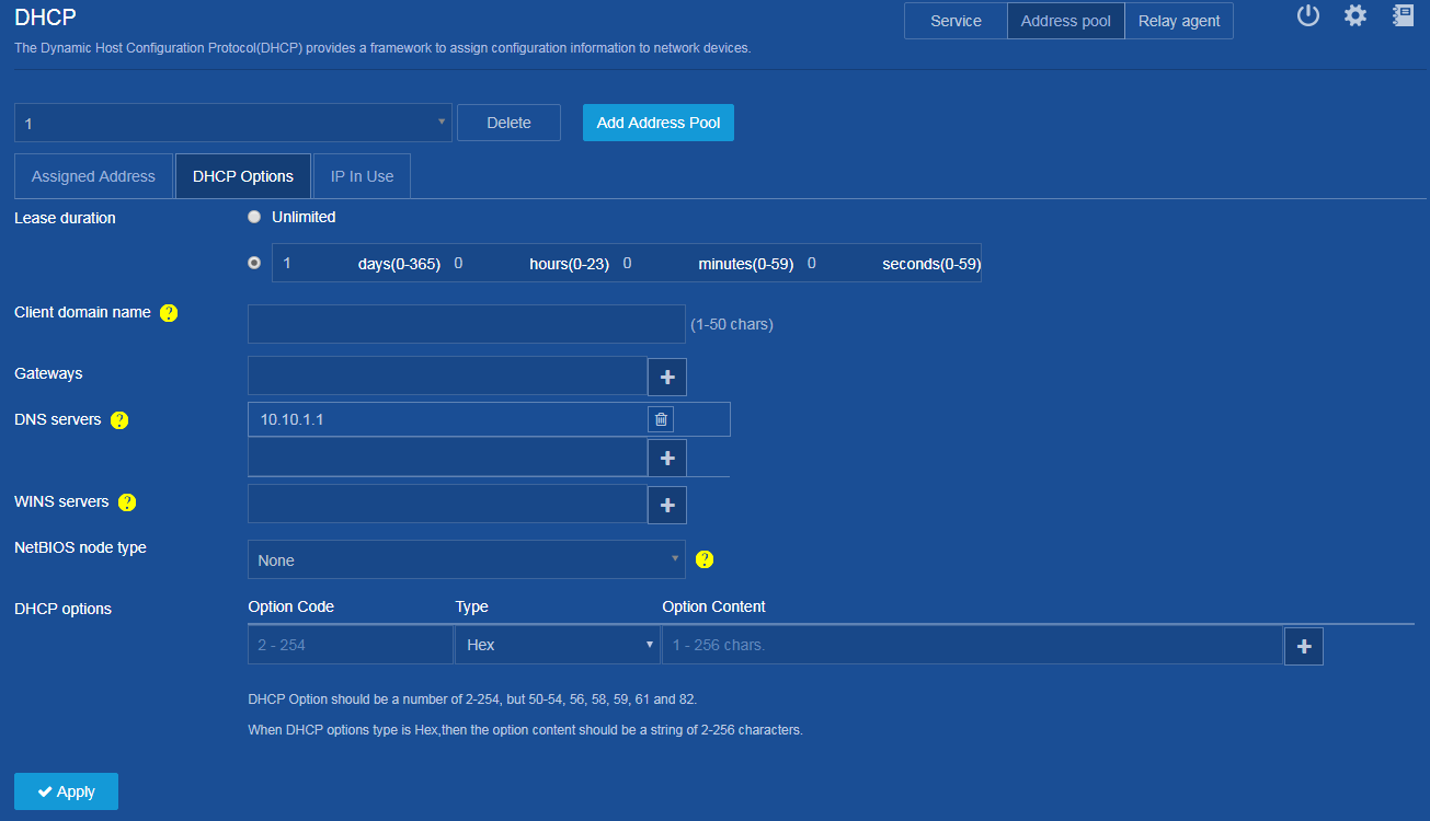
f. Click the DHCP Options
tab, enter 10.10.1.1 as the
gateway in DHCP address pool 1,
and then click the add icon ![]() .
.
g. Click Apply.
The system displays a success message if you configure DHCP address pool 1 successfully.
Figure 8 Specifying gateway in DHCP address pool 1
4. Save the configuration.
Click the save icon ![]() at the upper left of the page.
at the upper left of the page.
Configure DHCP relay agent (Switch B)
1. Configure VLAN.
a. From the left navigation pane, select Network > Links > VLAN.
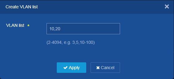
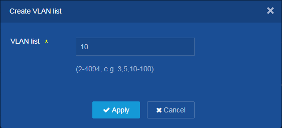
b. On the page that opens, click the create icon ![]() to create VLANs 10 and 20.
to create VLANs 10 and 20.
c. Add VLAN 10 and VLAN 20 to the VLAN list, and then click Apply.
Figure 9 Creating VLANs 10 and 20
d. Click the edit icon ![]() on the right of VLAN 10 to edit the settings of VLAN 10.
on the right of VLAN 10 to edit the settings of VLAN 10.
e. Add GE1/0/1 to the tagged port list of VLAN 10.
f. Select Configure VLAN interface at the IP address of the VLAN interface parameter.
g. Assign IP address 10.10.1.1/24 to VLAN-interface 10.
h. Click Apply.
The system displays a success message if you configure VLAN 10 successfully.
Figure 10 Configuring VLAN 10

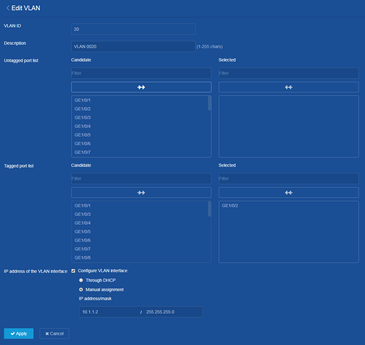
i. Click the edit icon ![]() on the right of VLAN 20 to edit the settings of VLAN 20.
on the right of VLAN 20 to edit the settings of VLAN 20.
j. Add GE1/0/2 to the tagged port list of VLAN 20.
k. Select Configure VLAN interface at the IP address of the VLAN interface parameter.
l. Assign IP address 10.1.1.2/24 to VLAN-interface 20.
m. Click Apply.
The system displays a success message if you configure VLAN 20 successfully.
Figure 11 Configuring VLAN 20
2. Configure DHCP relay agent.
a. From the left navigation pane, select Network > Service > DHCP.
b. On the page that opens, click Enable DHCP.
Figure 12 Enabling DHCP

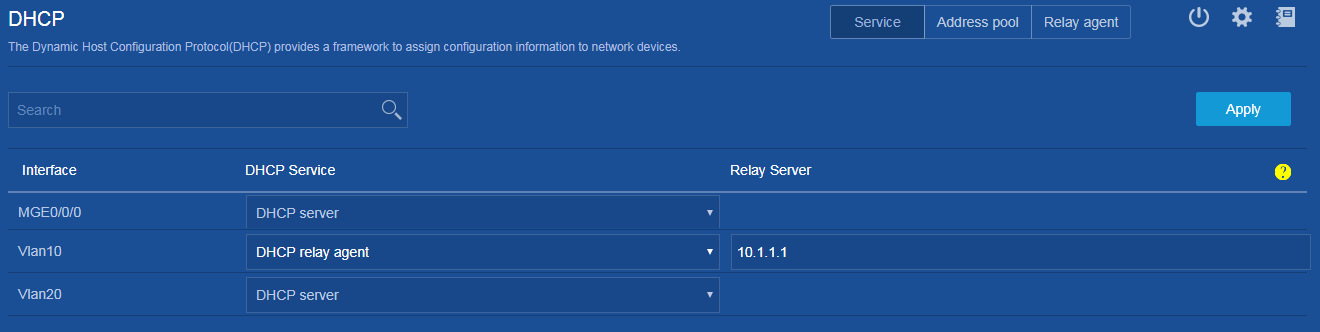
c. Click Service at the upper right of the page, and then set the DHCP service type to DHCP relay agent for VLAN-interface 10.
d. Click Apply.
The system displays a success message if you configure DHCP relay agent successfully.
Figure 13 Configuring DHCP relay agent mode
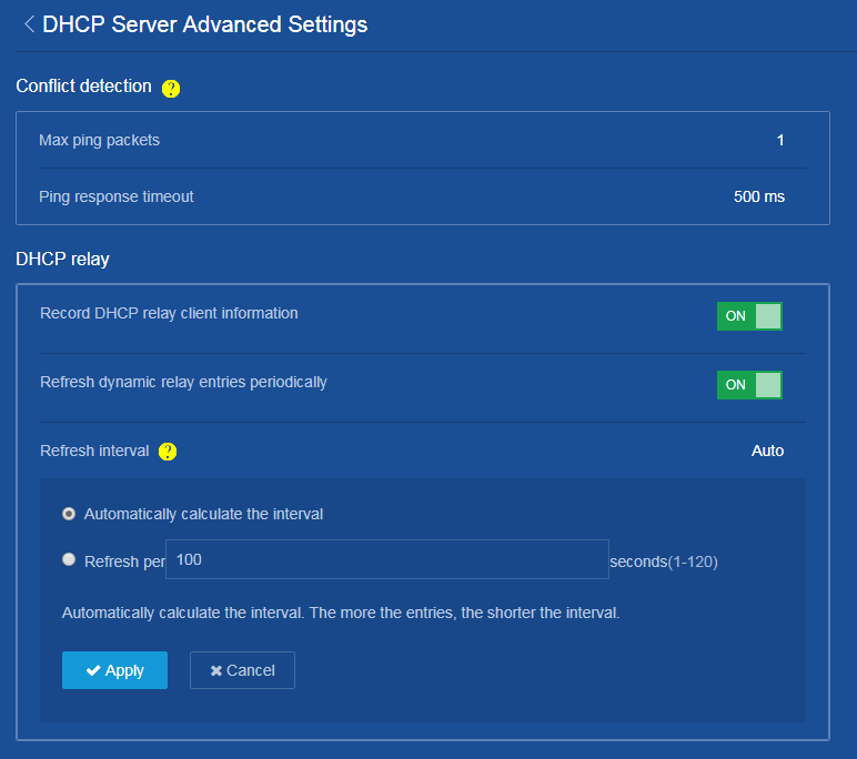
e. Click the ![]() icon
on the top right of the page to configure advanced DHCP settings. On the page
that opens, enable the relay agent to record client information and refresh
dynamically relay entries periodically, and then set the refresh interval to
100 seconds.
icon
on the top right of the page to configure advanced DHCP settings. On the page
that opens, enable the relay agent to record client information and refresh
dynamically relay entries periodically, and then set the refresh interval to
100 seconds.
f. Click Apply.
The system displays a success message if you configure the advanced DHCP settings successfully.
Figure 14 Configuring advanced DHCP settings
3. Save the configuration.
Click the save icon ![]() at the upper left of the page.
at the upper left of the page.
Configure DHCP client (Switch A)
1. Configure VLAN.
a. From the left navigation pane, select Network > Links > VLAN.
b. On the page that opens, click the create icon ![]() to create VLAN 10.
to create VLAN 10.
c. Add VLAN 10 to the VLAN list, and then click Apply.
Figure 15 Creating VLAN 10
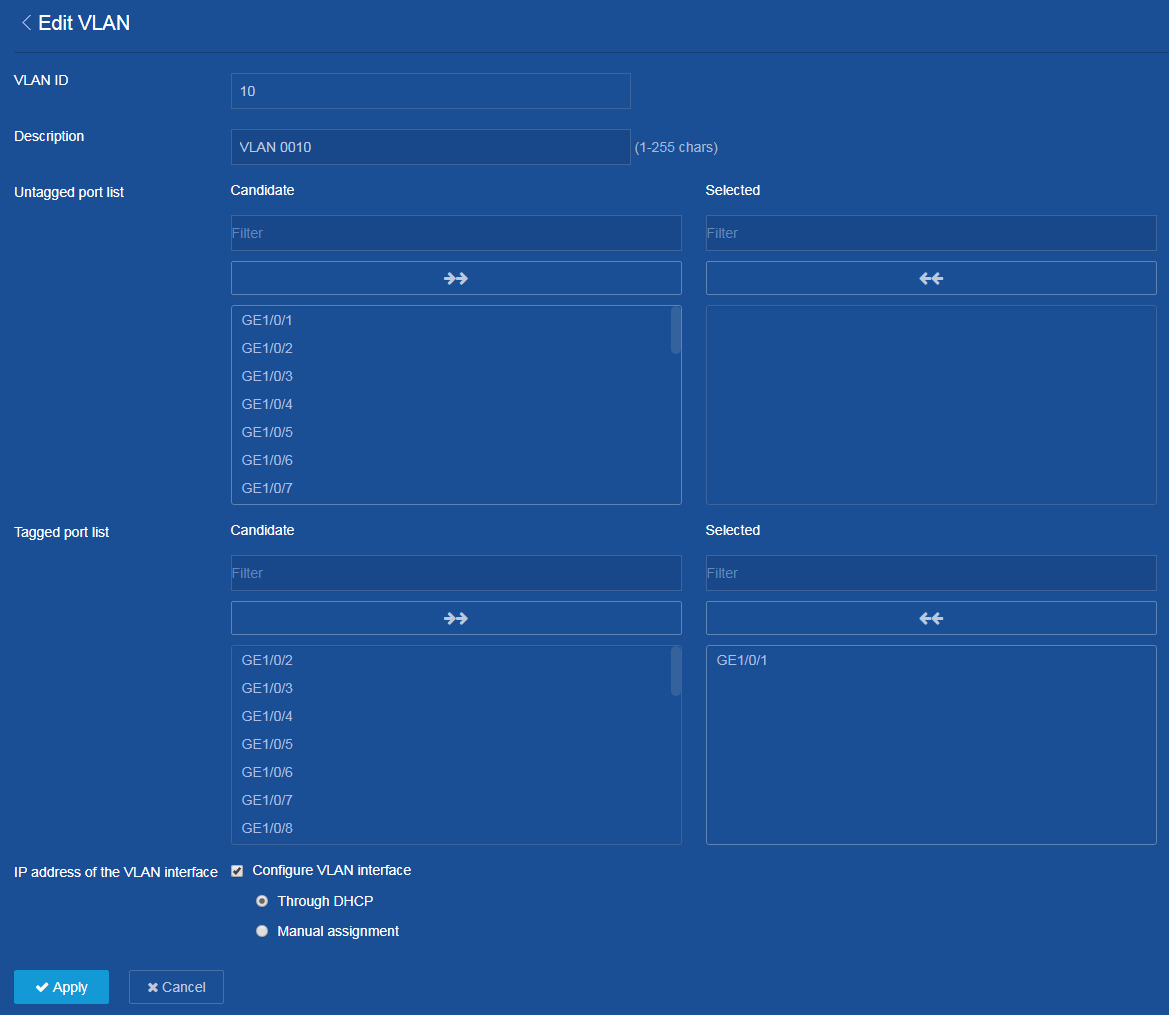
d. Click the edit icon ![]() on the right of VLAN 10 to edit the settings of VLAN 10.
on the right of VLAN 10 to edit the settings of VLAN 10.
e. Add GE1/0/1 to the tagged port list of VLAN 10.
f. Select Configure VLAN interface and Through DHCP at the IP address of the VLAN interface parameter.
g. Click Apply.
The system displays a success message if you configure VLAN 10 successfully.
Figure 16 Configuring VLAN 10
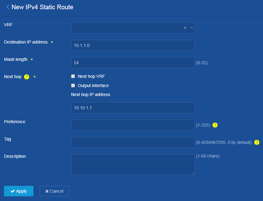
2. Configure static routes.
a. From the left navigation pane, select Network > Routing > Static Routing.
b. On the page that opens, click the ![]() icon on the right of IPv4 Static Routes.
icon on the right of IPv4 Static Routes.
c. Click the add icon ![]() to add an IPv4 static
route.
to add an IPv4 static
route.
d. Configure 10.1.1.0/24 as the destination and 10.10.1.1 as the next hop. Do not select Output interface at the Next hop parameter.
This route ensures the connectivity between the DHCP server and the client.
e. Configure other parameters as needed, and then click Apply.
Figure 17 Adding IPv4 static route
3. Save the configuration.
Click the save icon ![]() at
the upper left of the page.
at
the upper left of the page.
Verifying the configuration
· Verify that the DHCP server can dynamically assign an IP address from the desired subnet to the client.
To view the IP addresses assigned by the DHCP server, perform the following tasks:
a. From the left navigation pane on the switch configuration page, select Network > Service > DHCP.
b. Click Address pool at the upper right of the DHCP configuration page.
c. Click the IP in Use tab.
· Verify that the relay agent has a relay entry for the client.
· Verify that the client has obtained an IP address through DHCP correctly.
