- Released At: 30-03-2023
- Page Views:
- Downloads:
- Table of Contents
- Related Documents
-
H3C Virtual AP Technology Best Practices
Copyright © 2023 New H3C Technologies Co., Ltd. All rights reserved.
No part of this manual may be reproduced or transmitted in any form or by any means without prior written consent of New H3C Technologies Co., Ltd.
Except for the trademarks of New H3C Technologies Co., Ltd., any trademarks that may be mentioned in this document are the property of their respective owners.
This document provides generic technical information, some of which might not be applicable to your products.
The information in this document is subject to change without notice.
Contents
Virtual AP configuration examples
Configuring internal network devices
Configuring iMC for the internal network
Configuring external network devices
Configuring iMC for the external network
About virtual APs
Technical background
Traditional solutions for internal and external network isolation include:
· Traditional logical isolation
In this solution, one AC is deployed to manage both networks and perform VLAN-based service isolation. Internal and external resources cannot be fully isolated and security issues might occur.
· Physical isolation
A set of AC and AP are deployed for each network to completely isolate the two networks. This solution is difficult to implement and increases the deployment cost.
To address the issues concerning security protection, resource allocation, and different network service requirements, H3C comes up with the virtual AP solution.
Application scenarios
The virtual AP technology is first developed for the healthcare industry. By deploying the technology, hospitals can provide wireless networks for internal use and external access, respectively:
· For hospital staff, the internal network services provide treatment data collection, vital signs monitoring, and ambient temperature, humidity, and equipment running state monitoring.
· For patients and their family, the external network services provide online appointment booking, medical guidance, queue system, mobile payment, and other basic network services.
The virtual AP technology deploys one AC for internal access and the other AC for external access to control one physical AP and one virtual AP, respectively. This solution can implement physical isolation, avoid resource usage conflict, and provide custom service policies and authentication policies based on different user groups and services.
Virtual AP networking
Figure 1 Virtual AP networking
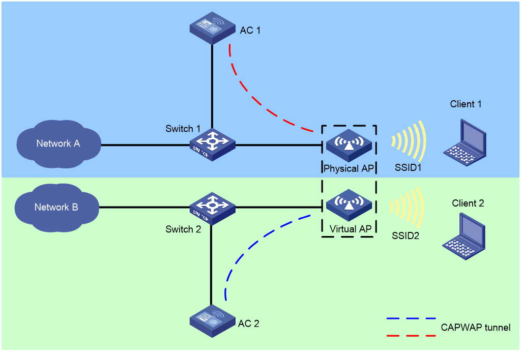
The virtual AP networking operates as follows:
1. Install an AP license on AC 1 and establish a CAPWAP tunnel that connects Ethernet interface 1 of the physical AP to AC 1.
2. Create a virtual AP from the physical AP and establish another CAPWAP tunnel that connects Ethernet interface 2 of the virtual AP to AC 2.
|
|
NOTE: Only physical APs require licenses to come online. |
3. Use AC 1 and AC 2 to manage the physical AP and virtual AP, respectively. In this way, the two WLANs can provide isolated wireless services to different users.
Users can create corresponding virtual APs from multiple physical APs, and use one AC to manage the physical APs and another AC to manage the virtual APs. In this way, you can isolate multiple WLANs without any extra use of APs, which can help reduce the WLAN deployment cost.
Mechanism
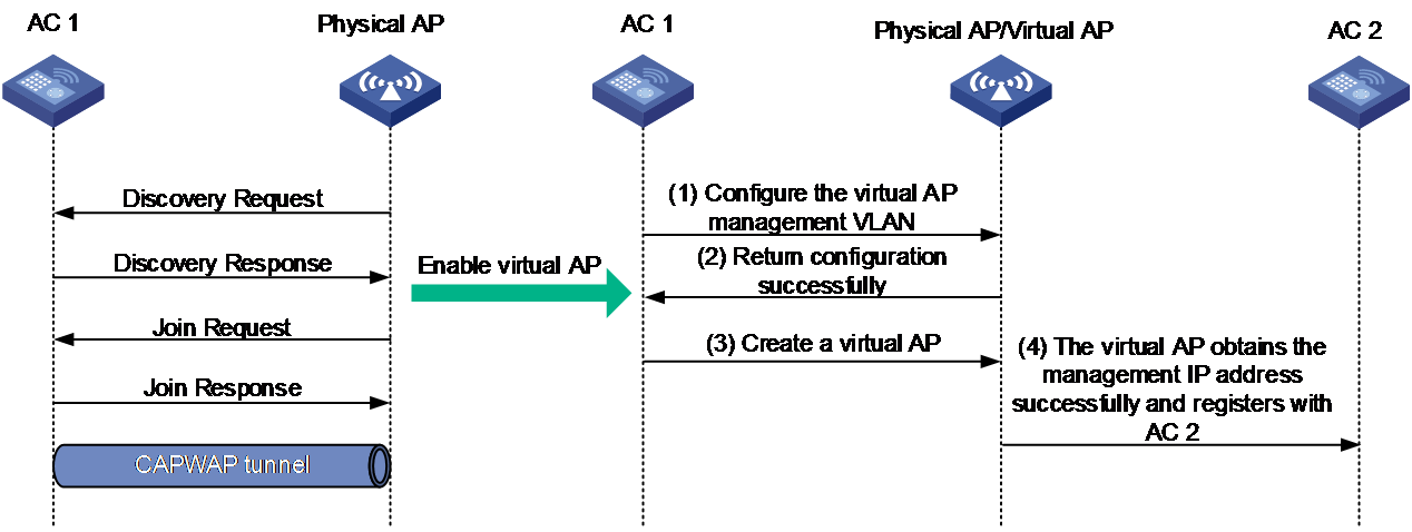
Virtual AP creation
As shown in Figure 2, to create a virtual AP, onboard the physical AP, enable the virtual AP feature, and specify the IP address of AC 2 to which the virtual AP will connect. Then, a virtual AP is created as follows:
1. Specify the management VLAN for the virtual AP on AC 1.
2. Configure the management VLAN to obtain the IP address through DHCP.
3. Create the virtual AP on AC 1.
If the virtual AP obtains the management IP address successfully, it registers with AC 2.
If the virtual AP fails to obtain the management IP address, it creates a timer and keeps obtaining the address until the timer expires.
Figure 2 Creating a virtual AP
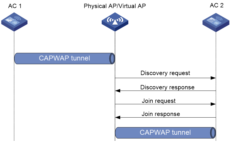
Virtual AP association
|
|
IMPORTANT: If software upgrade is enabled and the virtual AP uses a different version from AC 2, the AP cannot come online from the AC. In this case, disable software upgrade first. |
After the physical AP creates a data block and obtains the management VLAN IP address for the virtual AP, the virtual AP enters the CAPWAP state machine and starts to register with AC 2 as follows:
1. The virtual AP sends a discovery request to AC 2.
2. Upon receiving the discovery request, AC 2 determines whether to send a discovery response based on the AP model and capability sets.
3. The virtual AP sends a join request to AC 2.
4. Upon receiving the join request, AC 2 identifies whether AP template matching information such as AP SN exists in the request.
¡ If a match is identified, AC 2 returns with a join response.
¡ If no match is identified, AC 2 verifies that the requester is a virtual AP by its label and does not respond to the virtual AP.
5. The virtual AP requests for the downloading configuration information at the CAPWAP configuration downloading phase.
6. The virtual AP comes online from AC 2 successfully.
Figure 3 Virtual AP association
Virtual AP configuration examples
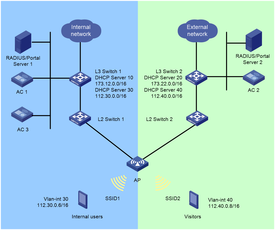
Network configuration
In a centralized forwarding architecture, ACs are connected to Layer 3 switches. The Layer 3 switches act as DHCP servers to assign IP addresses to APs and clients. Layer 2 switches provide PoE for APs, and the physical and virtual APs establish two CAPWAP tunnels with AC 1 and AC 2, respectively.
· For the internal network:
¡ L3 Switch 1 acts as a DHCP server to assign IP addresses to the physical AP and clients.
¡ The physical AP obtains an IP address from DHCP Server 10 and the AP belongs to VLAN 10.
¡ Internal users access the internal network from VLAN 30. MAC address authentication, 802.1X authentication, and portal authentication are supported.
¡ Enable seamless roaming.
¡ AC 3 acts as the AP dual-link backup for AC 1.
¡ The internal iMC acts as a portal authentication server, portal Web server, and RADIUS server simultaneously.
· For the external network:
¡ L3 Switch 2 acts as a DHCP server to assign IP addresses to the virtual AP and clients.
¡ The virtual AP obtains an IP address from DHCP Server 20 and the AP belongs to VLAN 20.
¡ External users access the network from VLAN 40. MAC address authentication, 802.1X authentication, and portal authentication are supported.
¡ The external iMC acts as a portal authentication server, portal Web server, and RADIUS server simultaneously.
|
Device |
Interface |
IP address |
Device |
Interface |
IP address |
|
L3 Switch 1 |
Vlan-int 10 |
173.12.1.2/16 |
L3 Switch 2 |
Vlan-int 20 |
173.22.1.2/16 |
|
|
Vlan-int 30 |
112.30.0.1/16 |
|
Vlan-int 40 |
112.40.0.3/16 |
|
AC 1 |
Vlan-int 10 |
173.12.1.3/16 |
AC 2 |
Vlan-int 20 |
173.22.1.3/16 |
|
|
Vlan-int 30 |
112.30.0.2/16 |
|
Vlan-int 40 |
112.40.0.2/16 |
|
AC 3 |
Vlan-int 10 |
173.12.1.7/16 |
|
|
|
|
|
Vlan-int 30 |
112.30.0.3/16 |
|
|
|
Restrictions and guidelines
· ACs in the internal and external networks must be the same version.
· When the AP starts up without loading any configuration, the two uplink ports of the AP are access ports, the port PVID is 1, and the AP uses VLAN-interface 1 to send VLAN-untagged packets. To prevent loops, you must use the undo port trunk permit vlan vlan-pvid command on the physical interface that connects the AP to the external switch to forbid packets in the default port VLAN to pass. Note that the management VLAN and the service VLAN of the virtual AP cannot be configured as the default VLAN of the port.
· If the virtual AP and the physical AP use different management VLANs, you must forbid both VLAN 1 packets and the internal network VLAN packets to pass on the interface that connects the AP to the external switch. This prevents loops between the two uplink networks of the AP.
· You can create a maximum of one virtual AP from a physical AP.
· Virtual APs do not support the auto AP feature.
· Make sure the IP address of the AC that manages a physical AP is different from the IP address of the AC that manages its virtual AP and make sure the IP addresses are the same version.
· Enabling the virtual AP feature halves the maximum number of BSSes that can be created for a radio.
· Make sure no virtual AP exists in any AP or AP group view before disabling the virtual AP feature. If virtual APs exist, delete them before the disabling.
· To realize VLAN isolation for a physical AP and a virtual AP, configure the management VLAN used when the virtual AP comes online.
· To use the same management VLAN for a physical AP and a virtual AP, you must configure port isolation on the Ethernet interface of the AP.
· For a virtual AP to operate correctly, make sure its physical AP operates correctly. For example, the CAPWAP tunnel disconnection for the physical AP will cause the CAPWAP tunnel disconnection for its virtual AP.
Procedure
Configuring internal network devices
Configuring L3 Switch 1
1. Configure L3 Switch 1 interfaces.
# Create VLAN 10 and VLAN 30 and configure IP addresses for respective VLAN interfaces. Use VLAN 10 to forward traffic of the CAPWAP tunnel connecting AC 1 and the physical AP. Use VLAN 30 for internal client access.
<L3 switch1>system-view
[L3 switch1] vlan 10
[L3 switch1-vlan10] quit
[L3 switch1] interface vlan-interface 10
[L3 switch1-Vlan-interface10] ip address 173.12.1.2 255.255.0.0
[L3 switch1-Vlan-interface10] quit
[L3 switch1] vlan 30
[L3 switch1-vlan30] quit
[L3 switch1] interface vlan-interface 30
[L3 switch1-Vlan-interface30] ip address 112.30.0.1 255.255.0.0
[L3 switch1-Vlan-interface30] quit
# Create VLAN 50 for iMC server connection and configure an IP address for the VLAN interface.
[L3 switch1] vlan 50
[L3 switch1-vlan50] quit
[L3 switch1] interface vlan-interface 50
[L3 switch1-Vlan-interface50] ip address 173.18.4.99 255.255.255.0
[L3 switch1-Vlan-interface50] quit
# Add the interface connecting L3 Switch 1 and the iMC server to VLAN 50. (Details not shown.)
# Configure interface GigabitEthernet1/0/1 that connects L3 Switch 1 to AC 1 as a trunk port. Forbid VLAN 1 and permit VLAN 10 and VLAN 30 on the trunk port.
[L3 switch1] interface gigabitethernet 1/0/1
[L3 switch1-GigabitEthernet1/0/1] port link-type trunk
[L3 switch1-GigabitEthernet1/0/1] undo port trunk permit vlan 1
[L3 switch1-GigabitEthernet1/0/1] port trunk permit vlan 10 30
[L3 switch1-GigabitEthernet1/0/1] quit
# Configure interface GigabitEthernet1/0/4 that connects L3 Switch 1 and AC 3 as a trunk port. Forbid VLAN 1 and permit VLAN 10 and VLAN 30 on the trunk port.
[L3 switch1] interface gigabitethernet 1/0/4
[L3 switch1-GigabitEthernet1/0/4] port link-type trunk
[L3 switch1-GigabitEthernet1/0/4] undo port trunk permit vlan 1
[L3 switch1-GigabitEthernet1/0/4] port trunk permit vlan 10 30
[L3 switch1-GigabitEthernet1/0/4] quit
# Configure interface GigabitEthernet1/0/2 that connects L3 Switch 1 and L2 Switch 1 as a trunk port. Forbid VLAN 1 and permit VLAN 10 on the trunk port.
[L3 switch1] interface gigabitethernet 1/0/2
[L3 switch1-GigabitEthernet1/0/2] port link-type trunk
[L3 switch1-GigabitEthernet1/0/2] undo port trunk permit vlan 1
[L3 switch1-GigabitEthernet1/0/2] port trunk permit vlan 10
[L3 switch1-GigabitEthernet1/0/2] quit
# Configure an interface for L3 Switch 1 to connect to the uplink network and configure the default route. (Details not shown.)
2. Configure DHCP servers.
# Enable the DHCP server feature.
[L3 switch1] dhcp enable
# Use DHCP address pool 10 to assign address range 173.12.0.0/16 to the physical AP and configure the gateway IP address as 173.12.1.2.
[L3 switch1] dhcp server ip-pool 10
[L3 switch1-dhcp-pool-10] network 173.12.0.0 mask 255.255.0.0
[L3 switch1-dhcp-pool-10] gateway-list 173.12.1.2
# Use DHCP address pool 30 to assign address range 112.30.0.0/16 to clients and configure the gateway IP address as 112.30.0.1 and the DNS server address as 112.30.0.1. The assigned DNS server address is the gateway address in this example. The DNS server address varies by network configuration.
[L3 switch1] dhcp server ip-pool 30
[L3 switch1-dhcp-pool-30] network 112.30.0.0 mask 255.255.0.0
[L3 switch1-dhcp-pool-30] gateway-list 112.30.0.1
[L3 switch1-dhcp-pool-30] dns-list 112.30.0.1
[L3 switch1-dhcp-pool-30] quit
Configuring L2 Switch 1
# Create VLAN 10 as the management VLAN for the physical AP.
<L2 switch1> system-view
[L2 switch1] vlan 10
[L2 switch1-vlan10] quit
# Configure interface GigabitEthernet1/0/1 that connects L2 Switch 1 to L3 Switch 1 as a trunk port. Forbid VLAN 1 and permit VLAN 10 on the trunk port.
[L2 switch1] interface gigabitEthernet 1/0/1
[L2 switch1-GigabitEthernet1/0/1] port link-type trunk
[L2 switch1-GigabitEthernet1/0/1] undo port trunk permit vlan 1
[L2 switch1-GigabitEthernet1/0/1] port trunk permit vlan 10
[L2 switch1-GigabitEthernet1/0/1] quit
# Configure interface GigabitEthernet1/0/2 that connects L2 Switch 1 to the physical AP as a trunk port. Forbid VLAN 1 and permit VLAN 10 on the trunk port. Enable PoE.
[L2 switch1] interface gigabitEthernet 1/0/2
[L2 switch1-GigabitEthernet1/0/2] port link-type trunk
[L2 switch1-GigabitEthernet1/0/2] undo port trunk permit vlan 1
[L2 switch1-GigabitEthernet1/0/2] port trunk pvid vlan 10
[L2 switch1-GigabitEthernet1/0/2] port trunk permit vlan 10
[L2 switch1-GigabitEthernet1/0/2] poe enable
[L2 switch1-GigabitEthernet1/0/2] quit
Configuring AC 1
1. Configure internal network interfaces for AC 1.
# Create VLAN 10 and its interface and specify an IP address for the interface. The physical AP obtains and uses the IP address to establish the primary CAPWAP tunnel with AC 1.
<AC1> system-view
[AC1] vlan 10
[AC1-vlan10] quit
[AC1] interface vlan-interface 10
[AC1-Vlan-interface10] ip address 173.12.1.3 255.255.0.0
[AC1-Vlan-interface10] quit
# Create VLAN 30 and its interface and specify an IP address for the interface. Internal clients use the VLAN to access the network.
[AC1] vlan 30
[AC1-vlan30] quit
[AC1] interface vlan-interface 30
[AC1-Vlan-interface30] ip address 112.30.0.2 255.255.0.0
[AC1-Vlan-interface30] quit
# Configure interface GigabitEthernet1/0/1 that connects AC 1 to L3 Switch 1 as a trunk port. Forbid VLAN 1 and permit VLAN 10 and VLAN 30 on the trunk port.
[AC1] interface gigabitethernet 1/0/1
[AC1-GigabitEthernet1/0/1] port link-type trunk
[AC1-GigabitEthernet1/0/1] undo port trunk permit vlan 1
[AC1-GigabitEthernet1/0/1] port trunk permit vlan 10 30
[AC1-GigabitEthernet1/0/1] quit
# Make sure that AC 1 can communicate with iMC and configure a route based on the network configuration.
[AC1] ip route-static 173.18.4.100 32 173.12.1.2
2. Configure an AP and deploy configurations to the AP.
# Create AP ap1 with model WA6636.
[AC1] wlan ap ap1 model WA6636
# Set the AP SN to 219801A23U8204P000C3.
[AC1-wlan-ap-ap1] serial-id 219801A23U8204P000C3
# Enable remote configuration synchronization.
[AC1-wlan-ap-ap1] remote-configuration enable
# Deploy VLAN 20 to AP ap1 in AP view. VLAN 20 is the management VLAN for the virtual AP.
[AC1-wlan-ap-ap1] vlan 20
[AC11-wlan-ap-ap1-vlan20] quit
# Deploy interface gigabitethernet 2 to AP ap1. Interface gigabitethernet 2 connects AP ap1 to L2 Switch 2 and permits VLAN 20 on the interface.
[AC1-wlan-ap-ap1] gigabitethernet 2
[AC1-wlan-ap-ap1-gigabitethernet-2] port link-type trunk
[AC1-wlan-ap-ap1-gigabitethernet-2] undo port trunk permit vlan 1
[AC1-wlan-ap-ap1-gigabitethernet-2] port trunk permit vlan 20
[AC1-wlan-ap-ap1-gigabitethernet-2] quit
# Synchronize the VLAN and interface configuration commands in AP view to AP ap1.
[AC1-wlan-ap-ap1] remote-configuration synchronize
3. Enable virtual AP globally.
# Enable virtual AP globally.
[AC1] wlan virtual-ap enable
4. Create a virtual AP.
# Create a virtual AP, specify the IP address for the external AC with which the virtual AP registers, and configure the virtual AP management VLAN.
[AC1] wlan ap ap1
[AC1-wlan-ap-ap1] virtual-ap ac-address ip 173.22.1.3 management-vlan 20
[AC1-wlan-ap-ap1] quit
5. Configure AP dual-link backup.
# Enter AP view for AP ap1 and specify the AP connection priority as 7.
[AC1] wlan ap ap1
[AC1-wlan-ap-ap1] priority 7
# Specify the IP address for the backup AC as 173.12.1.7.
[AC1-wlan-ap-ap1] backup-ac ip 173.12.1.7
# Enable CAPWAP tunnel preemption.
[AC1-wlan-ap-ap1] wlan tunnel-preempt enable
[AC1-wlan-ap-ap1] quit
6. Configure a RADIUS scheme.
# Create RADIUS scheme office and enter its view.
[AC1] radius scheme office
# Configure the IP addresses and keys for primary authentication and accounting servers of the RADIUS scheme.
[AC1-radius-office] primary authentication 173.18.4.100
[AC1-radius-office] primary accounting 173.18.4.100
[AC1-radius-office] key authentication simple 12345678
[AC1-radius-office] key accounting simple 12345678
# Forbid usernames sent to the RADIUS server to contain any domain name.
[AC1-radius-office] user-name-format without-domain
# Specify the source IP address as 173.12.1.3 for the device to send RADIUS packets.
[AC1-radius-office] nas-ip 173.12.1.3
[AC1-radius-office] quit
# Enable RADUIS session control.
[AC1] radius session-control enable
# Enable RADIUS DAE service and enter RADIUS DAE server view.
[AC1] radius dynamic-author server
# Specify IP address 173.18.4.100 for the RADIUS DAE client and configure the shared key as plaintext string radius for DAE packet exchange.
[AC1-radius-da-server] client ip 173.18.4.100 key simple 12345678
[AC1-radius-da-server] quit
7. Configure authentication domains.
# Create ISP domain office1 and enter its view.
[AC1] domain office1
# Use RADIUS scheme office for LAN-access users as the authentication, licensing, and accounting scheme.
[AC1-isp-office1] authentication lan-access radius-scheme office
[AC1-isp-office1] authorization lan-access radius-scheme office
[AC1-isp-office1] accounting lan-access radius-scheme office
# Set the idle cut time to 15 minutes and set the generated traffic in the period to 1024 bytes for users in ISP domain office1.
[AC1-isp-office1] authorization-attribute idle-cut 15 1024
[AC1-isp-office1] quit
# Create ISP domain office2 and enter its view.
[AC1] domain office2
# Use RADIUS scheme office for portal users as the authentication, licensing, and accounting scheme.
[AC1-isp-office2] authentication portal radius-scheme office
[AC1-isp-office2] authorization portal radius-scheme office
[AC1-isp-office2] accounting portal radius-scheme office
# Set the idle cut time to 15 minutes and set the generated traffic in the period to 1024 bytes for users in ISP domain office2.
[AC1-isp-office2] authorization-attribute idle-cut 15 1024
[AC1-isp-office2] quit
8. Configure MAC authentication.
# Specify h3cmac for the username in a fixed format and specify plaintext string 12345678 for the password.
[AC1] mac-authentication user-name-format fixed account h3cmac password simple 12345678
# Create wireless service template 1 and specify int-mac for the SSID.
[AC1] wlan service-template 1
[AC1-wlan-st-1] ssid int-mac
# Enable VLAN 30 for wireless service template 1.
[AC1-wlan-st-1] vlan 30
# Configure the user authentication method as MAC authentication and specify office1 for the ISP domain.
[AC1-wlan-st-1] client-security authentication-mode mac
[AC1-wlan-st-1] mac-authentication domain office1
# Enable BSS transition management (BTM).
[AC1-wlan-st-1] bss transition-management enable
# (Optional.) Configure BTM disassociation. With BTM disassociation configured, an AP does not forcibly log off a client if that client has not disassociated with that AP when the default disassociation timer expires.
[AC1-wlan-st-1] bss transition-management disassociation
# (Optional.) Enable data transmission holding during roaming.
[AC1-wlan-st-1] sacp roam-optimize traffic-hold enable advanced
# Enable service template 1.
[AC1-wlan-st-1] service-template enable
[AC1-wlan-st-1] quit
9. Configure 802.1X authentication.
# Configure the 802.1X authentication method as EAP.
[AC1] dot1x authentication-method eap
# Create wireless service template 2 and specify int-1x for the SSID.
[AC1] wlan service-template 2
[AC1-wlan-st-2] ssid int-1x
# Enable VLAN 30 for wireless service template 2.
[AC1-wlan-st-2] vlan 30
# Configure the AKM as 802.1X, cypher suite as CCMP, and security IE as RSN.
[AC1-wlan-st-2] akm mode dot1x
[AC1-wlan-st-2] cipher-suite ccmp
[AC1-wlan-st-2] security-ie rsn
# Configure the user authentication method as 802.1X and specify office1 for the ISP domain.
[AC1-wlan-st-2] client-security authentication-mode dot1x
[AC1-wlan-st-2] dot1x domain office1
# Enable BSS transition management (BTM).
[AC1-wlan-st-2] bss transition-management enable
# (Optional.) Configure BTM disassociation. With BTM disassociation configured, an AP does not forcibly log off a client if that client has not disassociated with that AP when the default disassociation timer expires.
AC1-wlan-st-2] bss transition-management disassociation
# (Optional.) Enable data transmission holding during roaming.
[AC1-wlan-st-2] sacp roam-optimize traffic-hold enable advanced
# Enable service template 2.
[AC1-wlan-st-2] service-template enable
[AC1-wlan-st-2] quit
10. Configure portal authentication.
# Specify server name newpt, IP address 173.18.4.100, and port number 50100 for the portal authentication server.
[AC1] portal server newpt
[AC1-portal-server-newpt] ip 173.18.4.100 key simple 12345678
[AC1-portal-server-newpt] port 50100
[AC1-portal-server-newpt] quit
# Specify URL http://173.18.4.100:8080/portal for the portal Web server.
[AC1] portal web-server wbportal
[AC1-portal-websvr-wbportal] url http://173.18.4.100:8080/portal
[AC1-portal-websvr-wbportal] quit
# Configure an IPv4 portal-free rule with rule ID 0 and destination address 173.18.4.100 to allow packets accessing the portal Web server to pass.
[AC1] portal free-rule 0 destination ip 173.18.4.100 24
# Configure two destination-based portal-free rules to allow packets accessing the DNS server to pass.
[AC1] portal free-rule 1 destination ip any udp 53
[AC1] portal free-rule 2 destination ip any tcp 53
# Disable the Rule ARP entry feature for portal clients.
[AC1] undo portal refresh arp enable
# Enable host identity check for portal clients.
[AC1] portal host-check enable
# Create wireless service template 3 and specify int-portal for the SSID.
[AC1] wlan service-template 3
[AC1-wlan-st-3] ssid int-portal
# Enable VLAN 30 for wireless service template 3.
[AC1-wlan-st-3] vlan 30
# Enable direct portal authentication.
[AC1-wlan-st-3] portal enable method direct
# Specify domain office2 for portal clients.
[AC1-wlan-st-3] portal domain office2
# Apply portal Web server wbportal on wireless service template 3.
[AC1-wlan-st-3] portal apply web-server wbportal
# Specify BAS-IP address 173.12.1.3 for portal packets.
[AC1-wlan-st-3] portal bas-ip 173.12.1.3
# Enable BSS transition management (BTM).
[AC1-wlan-st-3] bss transition-management enable
# (Optional.) Enable BTM disassociation. With BTM disassociation configured, an AP does not forcibly log off a client if that client has not disassociated with that AP when the default disassociation timer expires.
[AC1-wlan-st-3] bss transition-management disassociation
# (Optional.) Enable data transmission holding during roaming.
[AC1-wlan-st-3] sacp roam-optimize traffic-hold enable advanced
# Enable wireless service template 3.
[AC1–wlan-st-3] service-template enable
[AC1-wlan-st-3] quit
11. Bind service templates and configure seamless roaming.
# Enter radio 1 view of AP ap1.
[AC1] wlan ap ap1
[AC1-wlan-ap-ap1] radio 1
# Enable radio resource measurement.
[AC-wlan-ap-ap1-radio-1] resource-measure enable
# Enable client anti-sticky, set the RSSI threshold to 30, set the detection interval to 10 seconds, and enable BTM.
Adjust the RSSI threshold and detection interval based on the environment.
[AC1-wlan-ap-ap1-radio-1] sacp anti-sticky enable rssi 30 interval 10
# Enable AP ap1 to obtain BSS candidate information and set the measurement interval to 10 seconds.
[AC1-wlan-ap-ap1-radio-1] sacp roam-optimize bss-candidate-list enable interval 10
# Bind wireless service templates 1, 2, and 3 to radio 1 of AP ap1.
[AC1-wlan-ap-ap1-radio-1] radio enable
[AC1-wlan-ap-ap1-radio-1] service-template 1
[AC1-wlan-ap-ap1-radio-1] service-template 2
[AC1-wlan-ap-ap1-radio-1] service-template 3
[AC1-wlan-ap-ap1-radio-1] quit
[AC1-wlan-ap-ap1] quit
Configuring AC 3
1. Configure interfaces for AC 3.
# Create VLAN 10 and its VLAN interface and specify an IP address for the interface. The physical AP uses the IP address to establish a backup CAPWAP tunnel with AC 3.
<AC3> system-view
[AC3] vlan 10
[AC3-vlan10] quit
[AC3] interface vlan-interface 10
[AC3-Vlan-interface10] ip address 173.12.1.7 255.255.0.0
[AC3-Vlan-interface10] quit
# Create VLAN 30 and its VLAN interface and specify an IP for the interface. Internal clients use the VLAN to access the network.
[AC3] vlan 30
[AC3-vlan30] quit
[AC3] interface vlan-interface 30
[AC3-Vlan-interface30] ip address 112.30.0.3 255.255.0.0
[AC3-Vlan-interface30] quit
# Configure interface GigabitEthernet1/0/1 that connects AC3 to L3 Switch 1 as a trunk port. Forbid VLAN 1 and permit VLAN 10 and VLAN 30 on the interface.
[AC3] interface gigabitethernet 1/0/1
[AC3-GigabitEthernet1/0/1] port link-type trunk
[AC3-GigabitEthernet1/0/1] undo port trunk permit vlan 1
[AC3-GigabitEthernet1/0/1] port trunk permit vlan 10 30
[AC3-GigabitEthernet1/0/1] quit
# Make sure that AC 3 can communicate with iMC and configure a route based on the network configuration.
[AC3] ip route-static 173.18.4.100 32 173.12.1.2
2. Configure an AP and deploy configurations to the AP.
# Create AP ap1 with model WA6636.
[AC3] wlan ap ap1 model WA6636
# Set the AP SN to 219801A23U8204P000C3.
[AC3-wlan-ap-ap1] serial-id 219801A23U8204P000C3
# Enable remote configuration synchronization.
[AC3-wlan-ap-ap1] remote-configuration enable
# Deploy VLAN 20 to AP ap1 in AP view. VLAN 20 is the management VLAN for the virtual AP.
[AC3-wlan-ap-ap1] vlan 20
[AC3-wlan-ap-ap1-vlan20] quit
# Deploy interface gigabitethernet 2 to AP ap1. Interface gigabitethernet 2 connects AP ap1 to L2 Switch 2 and permits VLAN 20 on the interface.
[AC3-wlan-ap-ap1] gigabitethernet 2
[AC3-wlan-ap-ap1-gigabitethernet-2] port link-type trunk
[AC3-wlan-ap-ap1-gigabitethernet-2] undo port trunk permit vlan 1
[AC3-wlan-ap-ap1-gigabitethernet-2] port trunk permit vlan 20
[AC3-wlan-ap-ap1-gigabitethernet-2]quit
# Synchronize the VLAN and interface configuration commands in AP view to AP ap1.
[AC3-wlan-ap-ap1] remote-configuration synchronize
3. Enable virtual AP globally.
# Enable virtual AP globally
[AC3] wlan virtual-ap enable
4. Create a virtual AP.
# Create a virtual AP, specify the IP address for the external AC with which the virtual AP registers, and configure the virtual AP management VLAN.
[AC3] wlan ap ap1
[AC3-wlan-ap-ap1] virtual-ap ac-address ip 173.22.1.3 management-vlan 20
[AC3-wlan-ap-ap1] quit
5. Configure AP dual-link backup.
# Enter AP view for ap1 and specify the AP connection priority as 5.
[AC3] wlan ap ap1
[AC3-wlan-ap-ap1] priority 5
# Set the IP address for AC 3 to the same address 173.12.1.3 as AC 1.
[AC3-wlan-ap-ap1] backup-ac ip 173.12.1.3
6. Configure a RADIUS scheme.
# Create RADIUS scheme office and enter its view.
[AC3] radius scheme office
# Configure the IP addresses and keys for primary authentication and accounting servers of the RADIUS scheme.
[AC3-radius-office] primary authentication 173.18.4.100
[AC3-radius-office] primary accounting 173.18.4.100
[AC3-radius-office] key authentication simple 12345678
[AC3-radius-office] key accounting simple 12345678
# Forbid usernames sent to the RADIUS server to contain any domain name.
[AC3-radius-office] user-name-format without-domain
# Specify source IP address as 173.12.1.7 for the device to send RADIUS packets.
[AC3-radius-office] nas-ip 173.12.1.7
[AC3-radius-office] quit
# Enable RADUIS session control.
[AC3] radius session-control enable
# Enable RADIUS DAE service and enter RADIUS DAE server view.
[AC3] radius dynamic-author server
# Specify IP address 173.18.4.100 for the RADIUS DAE client and configure the shared key as plaintext string radius for DAE packet exchange.
[AC3-radius-da-server] client ip 173.18.4.100 key simple 12345678
[AC3-radius-da-server] quit
7. Configure authentication domains.
# Create ISP domain office1 and enter its view.
[AC3] domain office1
# Use RADIUS scheme office for LAN-access users as the authentication, licensing, and accounting scheme.
[AC3-isp-office1] authentication lan-access radius-scheme office
[AC3-isp-office1] authorization lan-access radius-scheme office
[AC3-isp-office1] accounting lan-access radius-scheme office
# Set the idle cut time to 15 minutes and set the generated traffic in the period to 1024 bytes for users in ISP domain office1.
[AC3-isp-office1] authorization-attribute idle-cut 15 1024
[AC3-isp-office1] quit
[AC3-isp-office1] quit
# Create ISP domain office2 and enter its view.
[AC3] domain office2
# Use RADIUS scheme office for portal users as the authentication, licensing, and accounting scheme.
[AC3-isp-office2] authentication portal radius-scheme office
[AC3-isp-office2] authorization portal radius-scheme office
[AC3-isp-office2] accounting portal radius-scheme office
# Set the idle cut time to 15 minutes and set the generated traffic in the period to 1024 bytes for users in ISP domain office2.
[AC3-isp-office2] authorization-attribute idle-cut 15 1024
[AC3-isp-office2] quit
8. Configure MAC authentication.
# Specify h3cmac for the username in a fixed format and specify plaintext string 12345678 for the password.
[AC3] mac-authentication user-name-format fixed account h3cmac password simple 12345678
# Create wireless service template 1 and specify int-mac for the SSID.
[AC3] wlan service-template 1
[AC3-wlan-st-1] ssid int-mac
# Enable VLAN 30 for wireless service template 1.
[AC3-wlan-st-1] vlan 30
# Configure the user authentication method as MAC authentication and specify office1 for the ISP domain.
[AC3-wlan-st-1] client-security authentication-mode mac
[AC3-wlan-st-1] mac-authentication domain office1
# Enable BSS transition management (BTM).
[AC3-wlan-st-1] bss transition-management enable
# (Optional.) Configure BTM disassociation. With BTM disassociation configured, an AP does not forcibly log off a client if that client has not disassociated with that AP when the default disassociation timer expires.
[AC3-wlan-st-1] bss transition-management disassociation
# (Optional.) Enable data transmission holding during roaming.
[AC3-wlan-st-1] sacp roam-optimize traffic-hold enable advanced
# Enable service template 1.
[AC3-wlan-st-1] service-template enable
[AC3-wlan-st-1] quit
9. Configure 802.1X authentication.
# Configure the 802.1X authentication method as EAP.
[AC3] dot1x authentication-method eap
# Create wireless service template 2 and specify int-1x for the SSID.
[AC3] wlan service-template 2
[AC3-wlan-st-2] ssid int-1x
# Enable VLAN 30 for wireless service template 2.
[AC3-wlan-st-2] vlan 30
# Configure the AKM as 802.1X, cypher suite as CCMP, and security IE as RSN.
[AC3-wlan-st-2] akm mode dot1x
[AC3-wlan-st-2] cipher-suite ccmp
[AC3-wlan-st-2] security-ie rsn
# Configure the user authentication method as 802.1X and specify office1 for the ISP domain.
[AC3-wlan-st-2] client-security authentication-mode dot1x
[AC3-wlan-st-2] dot1x domain office1
# Enable BSS transition management (BTM).
[AC3-wlan-st-2] bss transition-management enable
# (Optional.) Configure BTM disassociation. With BTM disassociation configured, an AP does not forcibly log off a client if that client has not disassociated with that AP when the default disassociation timer expires.
[AC3-wlan-st-2] bss transition-management disassociation
# (Optional.) Enable data transmission holding during roaming.
[AC3-wlan-st-2] sacp roam-optimize traffic-hold enable advanced
# Enable service template 2.
[AC3-wlan-st-2] service-template enable
[AC3-wlan-st-2] quit
10. Configure portal authentication.
# Specify server name newpt, IP address 173.18.4.100, and port number 50100 for the portal authentication server.
[AC3] portal server newpt
[AC3-portal-server-newpt] ip 173.18.4.100 key simple 12345678
[AC3-portal-server-newpt] port 50100
[AC3-portal-server-newpt] quit
# Configure URL http://173.18.4.100:8080/portal for the portal Web server.
[AC3] portal web-server wbportal
[AC3-portal-websvr-wbportal] url http://173.18.4.100:8080/portal
[AC3-portal-websvr-wbportal] quit
# Configure an IPv4 portal-free rule with rule ID 0 and destination address 173.18.4.100 to allow packets accessing the portal Web server to pass.
[AC3] portal free-rule 0 destination ip 173.18.4.100 24
# Configure two destination-based portal-free rules to allow packets accessing the DNS server to pass.
[AC3] portal free-rule 1 destination ip any udp 53
[AC3] portal free-rule 2 destination ip any tcp 53
# Disable the Rule ARP entry feature for portal clients.
[AC3] undo portal refresh arp enable
# Enable host identity check for portal clients.
[AC3] portal host-check enable
# Create wireless service template 3 and specify int-portal for the SSID.
[AC3] wlan service-template 3
[AC3-wlan-st-3] ssid int-portal
# Enable VLAN 30 for wireless service template 3.
[AC3-wlan-st-3] vlan 30
# Enable direct portal authentication.
[AC3-wlan-st-3] portal enable method direct
# Configure domain office2 for portal clients.
[AC3-wlan-st-3] portal domain office2
# Apply portal Web server wbportal on wireless service template 3.
[AC3-wlan-st-3] portal apply web-server wbportal
# Specify BAS-IP address 173.12.1.7 for portal packets.
[AC3-wlan-st-3] portal bas-ip 173.12.1.7
# Enable BSS transition management (BTM).
[AC3-wlan-st-3] bss transition-management enable
# (Optional.) Enable BTM disassociation. With BTM disassociation configured, an AP does not forcibly log off a client if that client has not disassociated with that AP when the default disassociation timer expires.
[AC3-wlan-st-3] bss transition-management disassociation
# (Optional.) Enable data transmission holding during roaming.
[AC3-wlan-st-3] sacp roam-optimize traffic-hold enable advanced
# Enable wireless service template 3.
[AC3–wlan-st-3] service-template enable
[AC3-wlan-st-3] quit
11. Bind service templates and configure seamless roaming.
# Enter radio 1 view of AP ap1.
[AC3] wlan ap ap1
[AC3-wlan-ap-ap1] radio 1
# Enable radio resource measurement.
[AC3-wlan-ap-ap1-radio-1] resource-measure enable
# Enable client anti-sticky, set the RSSI threshold to 30, set the detection interval to 10 seconds, and enable BTM.
Adjust the RSSI threshold and detection interval based on the environment.
[AC3-wlan-ap-ap1-radio-1] sacp anti-sticky enable rssi 30 interval 10
# Enable AP ap1 to obtain BSS candidate information and set the measurement interval to 10 seconds.
[AC3-wlan-ap-ap1-radio-1] sacp roam-optimize bss-candidate-list enable interval 10
# Bind wireless service templates 1, 2, and 3 to radio 1 of AP ap1.
[AC3-wlan-ap-ap1-radio-1] radio enable
[AC3-wlan-ap-ap1-radio-1] service-template 1
[AC3-wlan-ap-ap1-radio-1] service-template 2
[AC3-wlan-ap-ap1-radio-1] service-template 3
[AC3-wlan-ap-ap1-radio-1] quit
[AC3-wlan-ap-ap1] quit
Configuring iMC for the internal network
|
|
NOTE: This section uses iMC PLAT 7.1(E0303P10) and iMC UAM 7.1(E0303P10) to introduce the basic configuration for the RADIUS server and portal server. |
Configuring the RADIUS server
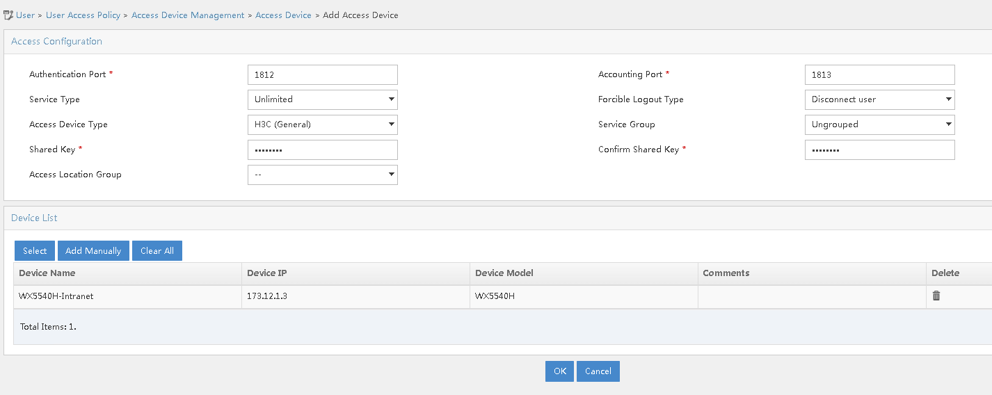
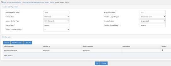
1. Add access devices.
# Add AC 1.
a. Log in to the iMC management platform. Access the User > User Access Policy > Access Device Management > Access Device page and click Add.
b. In the Access Configuration section, specify 12345678 for the shared key. The shared key must be the same as the configured key for RADIUS server on AC 1.
c. In the Device List section, click Add Manually. On the page that opens, enter the device IP address 173.12.1.3 and click OK. The device IP address must be the same as the configured NAS-IP address in radius scheme view on AC 1.
d. Use the default settings for other parameters.
e. Click OK.
Figure 5 Adding AC 1
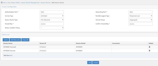
# Add AC 3.
a. Log in to the iMC management platform. Access the User > User Access Policy > Access Device Management > Access Device page and click Add.
b. In the Access Configuration section, specify 12345678 for the shared key. The shared key must be the same as the configured key for RADIUS server on AC 3.
c. In the Device List section, click Add Manually. On the page that opens, enter the device IP address 173.12.1.7 and click OK. The device IP address must be the same as the configured NAS-IP address in radius scheme view on AC 3.
d. Use the default settings for other parameters.
e. Click OK.
Figure 6 Adding AC 3
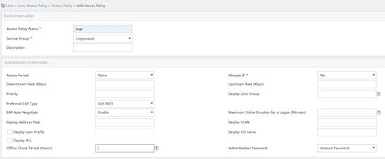
2. Add access policies.
# Create an access policy for MAC authentication.
a. Access the User > User Access Policy > Access Policy page. Click Add.
b. Specify mac for the access policy name.
c. Use the default settings for other parameters.
d. Click OK.
Figure 7 Adding an access policy for MAC authentication

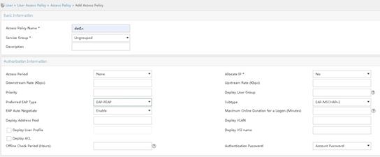
# Create an access policy for 802.1X authentication.
a. Access the User > User Access Policy > Access Policy page. Click Add.
b. Specify dot1x for the access policy name.
c. Select EAP-PEAP for the preferred EAP type and EAP-MSCHAPv2 for the subtype. The authentication subtype must be the same as the client authentication method.
d. Use the default settings for other parameters.
e. Click OK.
Figure 8 Adding an access policy for 802.1X authentication
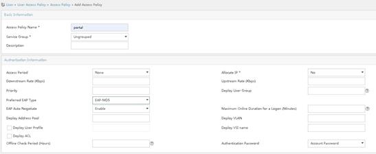
# Create an access policy for portal authentication.
a. Access the User > User Access Policy > Access Policy page. Click Add.
b. Specify portal for the access policy name.
c. Use the default settings for other parameters.
d. Click OK.
Figure 9 Adding an access policy for portal authentication

3. Add access services
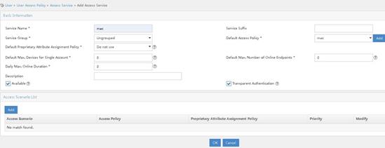
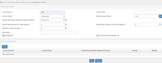
# Create an access service for MAC authentication.
a. Access the User > User Access Policy > Access Service page. Click Add.
b. Specify mac for the service name.
c. Select the created access policy mac for the default access policy.
d. Use the default settings for other parameters.
e. Click OK.
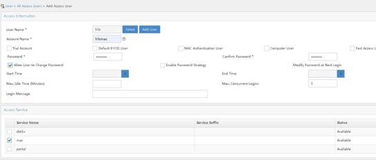
Figure 10 Adding an access service for MAC authentication
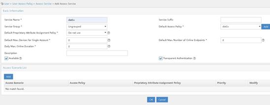
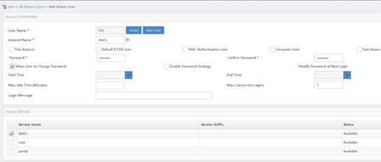
# Create an access service for 802.1X authentication.
a. Access the User > User Access Policy > Access Service page. Click Add.
b. Specify dot1x for the service name.
c. Select the created access policy dot1x for the default access policy.
d. Use the default settings for other parameters.
e. Click OK.
Figure 11 Adding an access service for 802.1X authentication

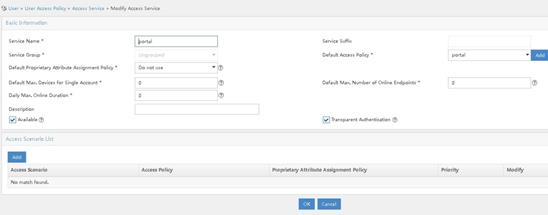
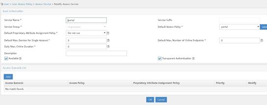
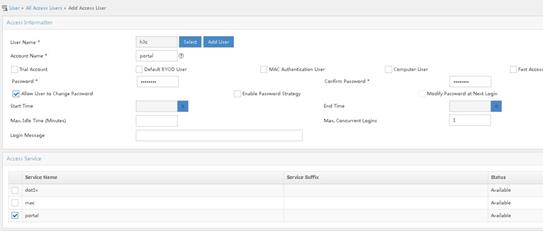
# Create an access service for portal authentication.
a. Access the User > User Access Policy > Access Service page. Click Add.
b. Specify portal for the service name.
c. Select the created access policy portal for the default access policy.
d. Use the default settings for other parameters.
e. Click OK.
Figure 12 Adding an access service for portal authentication
4. Add access users.
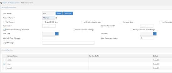
# Add an access user for MAC authentication.
a. Access the Users > All Access Users page. Click Add.
b. To add an existent user, click Select. To add a non-existent user, click Add User to add a new user.
c. Specify h3cmac for the account name and 12345678 for the password.
d. Select access service mac.
e. Click OK.
Figure 13 Adding an access user for MAC authentication
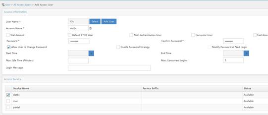
# Add an access user for 802.1X authentication.
a. Access the Users > All Access Users page. Click Add.
b. To add an existent user, click Select. To add a non-existent user, click Add User to add a new user.
c. Specify dot1x for the account name and 12345678 for the password.
d. Select access service dot1x.
e. Click OK.
Figure 14 Adding an access user for 802.1X authentication
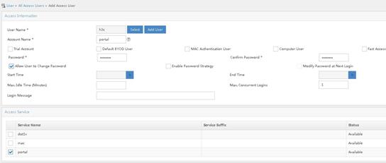
# Add an access user for portal authentication.
a. Access the Users > All Access Users page. Click Add.
b. To add an existent user, click Select. To add a non-existent user, click Add User to add a new user.
c. Specify portal for the account name and 12345678 for the password.
d. Select access service portal.
e. Click OK.
Figure 15 Adding an access user for portal authentication
Configuring the portal server
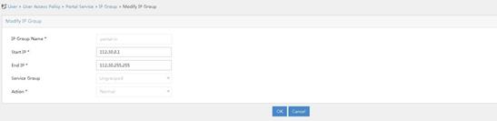
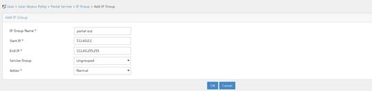
1. Configure an IP address group.
a. Access the User > User Access Policy > Portal Service > IP Group. Click Add.
b. Specify the IP address group name.
c. Specify the start address and end address. The configured address range must contain the user host IP address.
d. Select a service group. This example selects Ungrouped for the service group.
e. Select Normal for the IP address group type.
f. Click OK.
Figure 16 Adding an IP address group
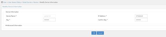
2. Add portal devices.
# Add AC 1.
a. Access the User > User Access Policy > Portal Service > Device. Click Add.
b. Specify the device name.
c. Specify IP address 173.12.1.3 for AC 1 in the internal network for client access.
d. Specify 12345678 for the key and make sure the configuration is consistent with that on the AC.
Figure 17 Adding AC 1
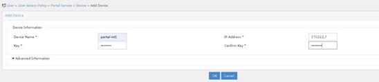
# Add AC 3.
a. Access the User > User Access Policy > Portal Service > Device. Click Add.
b. Specify the device name.
c. Specify IP address 173.12.1.7 for AC 3 in the internal network for client access.
d. Specify 12345678 for the key and make sure the configuration is consistent with that on the AC.
Figure 18 Adding AC 3
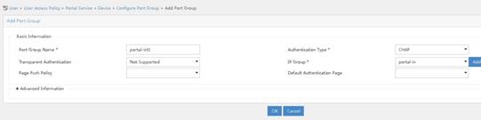
3. Associate IP address groups.
You can perform the following tasks to configure port group information for devices portal-int and portal-int1, respectively:
a. Click the icon for port group information management for a device in the Operation column of the portal device list.
b. Click Add to access the Add Port Group page.
c. Specify the port group name.
d. Select CHAP for the authentication type.
e. Select an IP address group. The selected IP address group must contain the user IP address.
f. Use default settings for other parameters.
g. Click OK.
h. From the navigation tree, select User Access Policy > Service Parameters > Validate System Configuration to commit the configuration changes.
Figure 19 Configuring port group information
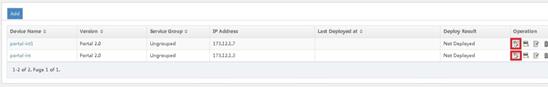
Figure 20 Associating IP address group for AC 1
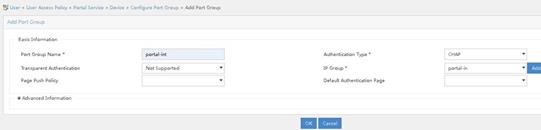
Figure 21 Associating IP address group for AC 3
Configuring external network devices
Configuring L3 Switch 2
1. Configure L3 Switch 2 interfaces.
# Create VLAN 20 and VLAN 40 and configure IP addresses for respective VLAN interfaces. Use VLAN 20 to forward traffic of the CAPWAP tunnel connecting the AC and the virtual AP. Use VLAN 40 for external client access.
<L3 switch> system-view
[L3 switch2] vlan 20
[L3 switch2-vlan20] quit
[L3 switch2]interface vlan-interface 20
[L3 switch2-Vlan-interface20] ip address 173.22.1.2 255.255.0.0
[L3 switch2-Vlan-interface20] quit
[L3 switch2] vlan 40
[L3 switch2-vlan40] quit
[L3 switch2]interface vlan-interface 40
[L3 switch2-Vlan-interface40] ip address 112.40.0.3 255.255.0.0
[L3 switch2-Vlan-interface40] quit
# Create VLAN 50 for iMC server connection and configure an IP address for the VLAN interface.
[L3 switch2] vlan 50
[L3 switch2-vlan50] quit
[L3 switch2] interface vlan-interface 50
[L3 switch2-Vlan-interface50] ip address 173.18.5.99 255.255.255.0
[L3 switch2-Vlan-interface50] quit
# Add the interface connecting L3 Switch 2 to the iMC server to VLAN 50. (Details not shown.)
# Configure interface GigabitEthernet1/0/5 that connects L3 Switch 2 to AC 2 as a trunk port. Forbid VLAN 1 and permit VLAN 20 and VLAN 40 on the trunk port.
[L3 switch2] interface gigabitethernet 1/0/5
[L3 switch2-GigabitEthernet1/0/5] port link-type trunk
[L3 switch2-GigabitEthernet1/0/5] undo port trunk permit vlan 1
[L3 switch2-GigabitEthernet1/0/5] port trunk permit vlan 20 40
[L3 switch2-GigabitEthernet1/0/5] quit
# Configure interface GigabitEthernet1/0/11 that connects L3 Switch 2 and L2 Switch 2 as a trunk port. Forbid VLAN 1 and permit VLAN 20 on the trunk port.
[L3 switch2] interface gigabitethernet 1/0/11
[L3 switch2-GigabitEthernet1/0/11] port link-type trunk
[L3 switch2-GigabitEthernet1/0/11] undo port trunk permit vlan 1
[L3 switch2-GigabitEthernet1/0/11] port trunk permit vlan 20
[L3 switch2-GigabitEthernet1/0/11] quit
# Configure an interface for L3 Switch 2 to connect to the uplink network and configure the default route. (Details not shown.)
2. Configure DHCP servers
# Enable the DHCP server feature.
[L3 switch2] dhcp enable
# Use DHCP address pool 20 to assign address range 173.22.0.0/16 to the virtual AP and configure the gateway IP address as 173.22.1.2.
[L3 switch2] dhcp server ip-pool 20
[L3 switch2-dhcp-pool-20] network 173.22.0.0 mask 255.255.0.0
[L3 switch2-dhcp-pool-20] gateway-list 173.22.1.2
# Use DHCP address pool 40 to assign address range 112.40.0.0/16 to clients and configure the gateway IP address as 112.40.0.3 and the DNS server address as 112.40.0.3. The assigned DNS server address is the gateway address in this example. The DNS server address depends on networks.
[L3 switch2] dhcp server ip-pool 40
[L3 switch2-dhcp-pool-40] network 112.40.0.0 mask 255.255.0.0
[L3 switch2-dhcp-pool-40] gateway-list 112.40.0.3
[L3 switch2-dhcp-pool-40] dns-list 112.40.0.3
[L3 switch2-dhcp-pool-40] quit
Configuring L2 Switch 2
# Create VLAN 20 as the management VLAN for the virtual AP.
<L2 switch2> system-view
[L2 switch2] vlan 20
[L2 switch2-vlan20] quit
# Configure interface GigabitEthernet1/0/1 that connects L2 Switch 2 to L3 Switch 2 as a trunk port. Forbid VLAN 1 and permit VLAN 20 on the trunk port.
[L2 switch2] interface gigabitEthernet 1/0/1
[L2 switch2-GigabitEthernet1/0/1] port link-type trunk
[L2 switch2-GigabitEthernet1/0/1] undo port trunk permit vlan 1
[L2 switch2-GigabitEthernet1/0/1] port trunk permit vlan 20
[L2 switch2-GigabitEthernet1/0/1] quit
# Configure interface GigabitEthernet1/0/2 that connects L2 Switch 2 to the virtual AP as a trunk port. Forbid VLAN 1 and permit VLAN 20 on the trunk port. Enable PoE.
[L2 switch2] interface gigabitEthernet 1/0/2
[L2 switch2-GigabitEthernet1/0/2] port link-type trunk
[L2 switch2-GigabitEthernet1/0/2] undo port trunk permit vlan 1
[L2 switch2-GigabitEthernet1/0/2] port trunk permit vlan 20
[L2 switch2-GigabitEthernet1/0/2] poe enable
[L2 switch2-GigabitEthernet1/0/2] quit
Configuring AC 2
1. Configure an external network interface for AC 2.
# Create VLAN 20 and its interface and specify an IP address for the interface. The virtual AP obtains and uses the IP address to establish a CAPWAP tunnel with AC 2.
<AC2> system-view
[AC2] vlan 20
[AC2-vlan20] quit
[AC2] interface vlan-interface 20
[AC2-Vlan-interface20] ip address 173.22.1.3 255.255.0.0
[AC2-Vlan-interface20] quit
# Create VLAN 40 and its interface and specify an IP address for the interface. External clients use the VLAN to access the network.
[AC2] vlan 40
[AC2-vlan40] quit
[AC2] interface vlan-interface 40
[AC2-Vlan-interface40] ip address 112.40.0.2 255.255.0.0
[AC2-Vlan-interface40] quit
# Configure interface GigabitEthernet1/0/1 that connects AC 2 to L3 Switch 2 as a trunk port. Forbid VLAN 1 and permit VLAN 20 and VLAN 40 on the trunk port.
[AC2] interface gigabitethernet 1/0/1
[AC2-GigabitEthernet1/0/1] port link-type trunk
[AC2-GigabitEthernet1/0/1] undo port trunk permit vlan 1
[AC2-GigabitEthernet1/0/1] port trunk permit vlan 20 40
[AC2-GigabitEthernet1/0/1] quit
# Make sure that AC 2 can communicate with iMC and configure a route based on the network configuration.
[AC2]ip route-static 173.18.5.100 32 173.22.1.2
2. Configure a virtual AP.
# Create virtual AP virtual-ap1 with model WA6636.
[AC2] wlan virtual-ap virtual-ap1 model WA6636
# Set the virtual AP SN to 219801A23U8204P000C3, which is the physical AP SN.
[AC2-wlan-virtual-ap-virtual-ap1] serial-id 219801A23U8204P000C3
[AC2-wlan-virtual-ap-virtual-ap1] quit
3. Configure a RADIUS scheme.
# Create RADIUS scheme office and enter its view.
[AC2] radius scheme office
# Configure the IP addresses and keys for primary authentication and accounting servers of the RADIUS scheme.
[AC2-radius-office] primary authentication 173.18.5.100
[AC2-radius-office] primary accounting 173.18.5.100
[AC2-radius-office] key authentication simple 12345678
[AC2-radius-office] key accounting simple 12345678
# Forbid usernames sent to the RADIUS server to contain any domain name.
[AC2-radius-office] user-name-format without-domain
# Specify source IP address as 173.22.1.3 for the device to send RADIUS packets.
[AC2-radius-office] nas-ip 173.22.1.3
[AC2-radius-office] quit
# Enable RADUIS session control.
[AC2] radius session-control enable
# Enable RADIUS DAE service and enter RADIUS DAE server view.
[AC2] radius dynamic-author server
# Specify IP address 173.18.5.100 for the RADIUS DAE client and configure the shared key as plaintext string radius for DAE packet exchange.
[AC2-radius-da-server] client ip 173.18.5.100 key simple 12345678
[AC2-radius-da-server] quit
4. Configure authentication domains.
# Create ISP domain office1 and enter its view.
[AC2] domain office1
# Use RADIUS scheme office for LAN-access users as the authentication, licensing, and accounting scheme.
[AC2-isp-office1] authentication lan-access radius-scheme office
[AC2-isp-office1] authorization lan-access radius-scheme office
[AC2-isp-office1] accounting lan-access radius-scheme office
# Set the idle cut time to 15 minutes and set traffic generated in the period to 1024 bytes for users in ISP domain office1.
[AC2-isp-office1] authorization-attribute idle-cut 15 1024
[AC2-isp-office1] quit
# Create ISP domain office2 and enter its view.
[AC2] domain office2
# Use RADIUS scheme office for portal users as the authentication, licensing, and accounting scheme.
[AC2-isp-office1] authentication portal radius-scheme office
[AC2-isp-office1] authorization portal radius-scheme office
[AC2-isp-office1] accounting portal radius-scheme office
# Set the idle cut time to 15 minutes and set traffic generated in the period to 1024 bytes for users in ISP domain office2.
[AC2-isp-office2] authorization-attribute idle-cut 15 1024
[AC2-isp-office2] quit
5. Configure MAC authentication.
# Specify h3cmac for the username in a fixed format and specify plaintext string 12345678 for the password.
[AC2] mac-authentication user-name-format fixed account h3cmac password simple 12345678
# Create wireless service template 1 and specify out-mac for the SSID.
[AC2] wlan service-template 1
[AC2-wlan-st-1] ssid out-mac
# Enable VLAN 40 for service template 1.
[AC2-wlan-st-1] vlan 40
# Configure the user authentication method as MAC authentication and specify office1 for the ISP domain.
[AC2-wlan-st-1] client-security authentication-mode mac
[AC2-wlan-st-1] mac-authentication domain office1
# Enable service template 1.
[AC2-wlan-st-1] service-template enable
[AC2-wlan-st-1] quit
6. Configure 802.1X authentication.
# Configure the 802.1X authentication method as EAP.
[AC2] dot1x authentication-method eap
# Create wireless service template 2 and specify out-1x for the SSID,
[AC2] wlan service-template 2
[AC2-wlan-st-2] ssid out-1x
# Enable VLAN 40 for service template 2.
[AC2-wlan-st-2] vlan 40
# Configure the AKM as 802.1X, cypher suite as CCMP, and security IE as RSN.
[AC2-wlan-st-2] akm mode dot1x
[AC2-wlan-st-2] cipher-suite ccmp
[AC2-wlan-st-2] security-ie rsn
# Configure the user authentication method as 802.1X and specify office1 for the ISP domain.
[AC2-wlan-st-2] client-security authentication-mode dot1x
[AC2-wlan-st-2] dot1x domain office1
# Enable service template 2.
[AC2-wlan-st-2] service-template enable
[AC2-wlan-st-2] quit
7. Configure portal authentication.
# Specify server name newpt, IP address 173.18.5.100, and port number 50100 for the portal authentication server.
[AC2] portal server newpt
[AC2-portal-server-newpt] ip 173.18.5.100 key simple 12345678
[AC2-portal-server-newpt] port 50100
[AC2-portal-server-newpt] quit
# Specify URL http://173.18.5.100:8080/portal for the portal Web server.
[AC2] portal web-server wbportal
[AC2-portal-websvr-wbportal] url http://173.18.5.100:8080/portal
[AC2-portal-websvr-wbportal] quit
# Configure an IPv4 portal-free rule with rule ID 0 and destination address 173.18.5.100 to allow packets accessing the portal Web server to pass.
[AC2] portal free-rule 0 destination ip 173.18.5.100 24
# Configure two destination-based portal-free rules to allow packets accessing the DNS server to pass.
[AC2] portal free-rule 1 destination ip any udp 53
[AC2] portal free-rule 2 destination ip any tcp 53
# Disable the Rule ARP entry feature for portal clients.
[AC2] undo portal refresh arp enable
# Enable host identity check for portal clients.
[AC2] portal host-check enable
# Create wireless service template 3 and specify out-portal for the SSID.
[AC2] wlan service-template 3
[AC2-wlan-st-3] ssid out-portal
# Enable VLAN 40 for service template 3.
[AC2-wlan-st-3] vlan 40
# Enable direct portal authentication.
[AC2-wlan-st-3] portal enable method direct
# Configure domain office2 for portal clients.
[AC2-wlan-st-3] portal domain office2
# Apply portal Web server wbportal on wireless service template 3.
[AC2-wlan-st-3] portal apply web-server wbportal
# Specify BAS-IP address 173.22.1.3 for portal packets.
[AC2-wlan-st-3] portal bas-ip 173.22.1.3
# Enable service template 3.
[AC2–wlan-st-3] service-template enable
[AC2-wlan-st-st1] quit
8. Bind service templates.
# Enter radio 1 view of virtual AP virtual-ap1 and bind service template 1, 2, and 3 to radio 1.
[AC2] wlan virtual-ap virtual-ap1
[AC2-wlan-virtual-ap-virtual-ap1] radio 1
[AC2-wlan-virtual-ap-virtual-ap1-radio 1] service-template 1
[AC2-wlan-virtual-ap-virtual-ap1-radio 1] service-template 2
[AC2-wlan-virtual-ap-virtual-ap1-radio 1] service-template 3
[AC2-wlan-virtual-ap-virtual-ap1-radio 1] quit
[AC2-wlan-virtual-ap-virtual-ap1] quit
Configuring iMC for the external network
|
|
NOTE: This section uses iMC PLAT 7.1 (E0303P10) and iMC UAM 7.1(E0303P10) to introduce the basic configuration for the RADIUS server and portal server. |
Configuring the RADIUS server
1. Add an access device.
# Add AC 2.
a. Log in to the iMC management platform. Access the User > User Access Policy > Access Device Management > Access Device page and click Add.
b. In the Access Configuration section, specify 12345678 for the shared key. The shared key must be the same as the configured key for RADIUS server on AC 2.
c. In the Device List section, click Add Manually. On the page that opens, enter the device IP address 173.22.1.3 and click OK. The device IP address must be the same as the configured NAS-IP address in radius scheme view on AC 2.
d. Use the default settings for other parameters.
e. Click OK.
Figure 22 Adding AC 2
2. Add access policies.
# Create an access policy for MAC authentication.
a. Access the User > User Access Policy > Access Policy page. Click Add.
b. Specify mac for the access policy name.
c. Use the default settings for other parameters.
d. Click OK.
Figure 23 Adding an access policy for MAC authentication
# Create an access policy for 802.1X authentication.
a. Access the User > User Access Policy > Access Policy page. Click Add.
b. Specify dot1x for the access policy name.
c. Select EAP-PEAP for the preferred EAP type and EAP-MSCHAPv2 for the subtype. The authentication subtype must be the same as the client authentication method.
d. Use the default settings for other parameters.
e. Click OK.
Figure 24 Adding an access policy for 802.1X authentication

# Create an access policy for portal authentication.
a. Access the User > User Access Policy > Access Policy page. Click Add.
b. Specify portal for the access policy name.
c. Use the default settings for other parameters.
d. Click OK.
Figure 25 Adding an access policy for portal authentication
3. Add access services
# Create an access service for MAC authentication.
a. Access the User > User Access Policy > Access Service page. Click Add.
b. Specify mac for the service name.
c. Select the created access policy mac for the default access policy.
d. Use the default settings for other parameters.
e. Click OK.
Figure 26 Adding an access service for MAC authentication
# Create an access service for 802.1X authentication.
a. Access the User > User Access Policy > Access Service page. Click Add.
b. Specify dot1x for the service name.
c. Select the created access policy dot1x for the default access policy.
d. Use the default settings for other parameters.
e. Click OK.
Figure 27 Adding an access service for 802.1X authentication
# Create an access service for portal authentication.
a. Access the User > User Access Policy > Access Service page. Click Add.
b. Specify portal for the service name.
c. Select the created access policy portal for the default access policy.
d. Use the default settings for other parameters.
e. Click OK.
Figure 28 Adding an access service for portal authentication
4. Add access users.
# Add an access user for MAC authentication.
a. Access the Users > All Access Users page. Click Add.
b. To add an existent user, click Select. To add a non-existent user, click Add User to add a new user.
c. Specify h3cmac for the account name and 12345678 for the password.
d. Select access service mac.
e. Click OK.
Figure 29 Adding an access user for MAC authentication
# Add an access user for 802.1X authentication.
a. Access the Users > All Access Users page. Click Add.
b. To add an existent user, click Select. To add a non-existent user, click Add User to add a new user.
c. Specify dot1x for the account name and 12345678 for the password.
d. Select access service dot1x.
e. Click OK.
Figure 30 Adding an access user for 802.1X authentication
# Add an access user for portal authentication.
a. Access the Users > All Access Users page. Click Add.
b. To add an existent user, click Select. To add a non-existent user, click Add User to add a new user.
c. Specify portal for the account name and 12345678 for the password.
d. Select access service portal.
e. Click OK.
Figure 31 Adding an access user for portal authentication
Configuring the portal server
1. Configure an IP address group.
a. Access the User > User Access Policy > Portal Service > IP Group. Click Add.
b. Specify the IP address group name.
c. Specify the start address and end address. The configured address range must contain the user host IP address.
d. Select a service group. This example selects Ungrouped for the service group.
e. Select Normal for the IP address group type.
f. Click OK.
Figure 32 Adding an IP address group
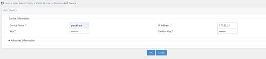
2. Add a portal device.
# Add AC 2.
a. Access the User > User Access Policy > Portal Service > Device. Click Add.
b. Specify the device name.
c. Specify IP address 173.22.1.3 for AC 2 in the external network to connect to clients.
d. Specify 12345678 for the key and make sure the configuration is consistent with that on the AC.
Figure 33 Adding AC 2
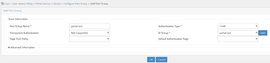
3. Associate an IP address group.
Perform the following tasks to configure port group information for device portal-out:
a. Click the icon for port group information management in the Operation column for device portal-out.
b. Click Add to access the Add Port Group page.
c. Specify the port group name.
d. Select CHAP for the authentication type.
e. Select an IP address group. The selected IP address group must contain the user IP address.
f. Use default settings for other parameters.
g. Click OK.
h. From the navigation tree, select User Access Policy > Service Parameters > Validate System Configuration to commit the configuration changes.
Figure 34 Configuring port group information

Figure 35 Associating IP address group for AC 2
Verifying the configuration
Execute the display wlan virtual-ap { all | name ap-name } command to view the virtual AP status on AC 2.
# Display information about all virtual APs.
<H3C>display wlan virtual-ap all
Total number of virtual-APs: 1
Total number of connected virtual-APs: 1
Total number of connected common virtual-APs: 1
Total number of connected virtual-WTUs: 0
Maximum supported APs: 3072
Remaining APs: 3071
AP information
State : I = Idle, J = Join, JA = JoinAck, IL = ImageLoad
C = Config, DC = DataCheck, R = Run, M = Master, B = Backup
AP name APID State Model Serial ID
ap1 1 R/M WA6636 219801A23U8204P000C3
Recommended models
The following device models are recommended for virtual AP application.
Table 1 Recommended models
|
Model |
Software version |
|
WX3820X |
ESS 1053P01 and later |
|
WX3840X |
ESS 1053P01 and later |
