| Title | Size | Downloads |
|---|---|---|
| H3C UniServer B5700 G6 Blade Server Processor Installation Quick Start-6W100-book.pdf | 2.66 MB |
- Related Documents
-
| Title | Size | Download |
|---|---|---|
| book | 2.66 MB |
Content
Overview
The following information is for generic reference. Plan your installation and removal procedures depending on the actual requirements.
The figures in this document are for illustration only.
Processor kit
The processor kit for a UniServer B5700 G6 server includes the following components:
· Processor
· Retaining bracket
· Heatsink
A T30 Torx electric screwdriver is required for processor installation. Prepare one yourself.
Preparing for installation
|
|
WARNING! To avoid bodily injury from hot surfaces, allow the server and its internal components to cool before touching them. |
|
|
CAUTION: · To avoid damage to the processors or system board, only H3C-authorized personnel and professional server engineers are allowed to install a processor. · To avoid ESD damage, put on an ESD wrist strap before installing a processor, and make sure the wrist strap is reliably grounded. |
To prepare for processor installation:
1. Back up all server data.
2. Power down the server.
3. Disconnect the power cords.
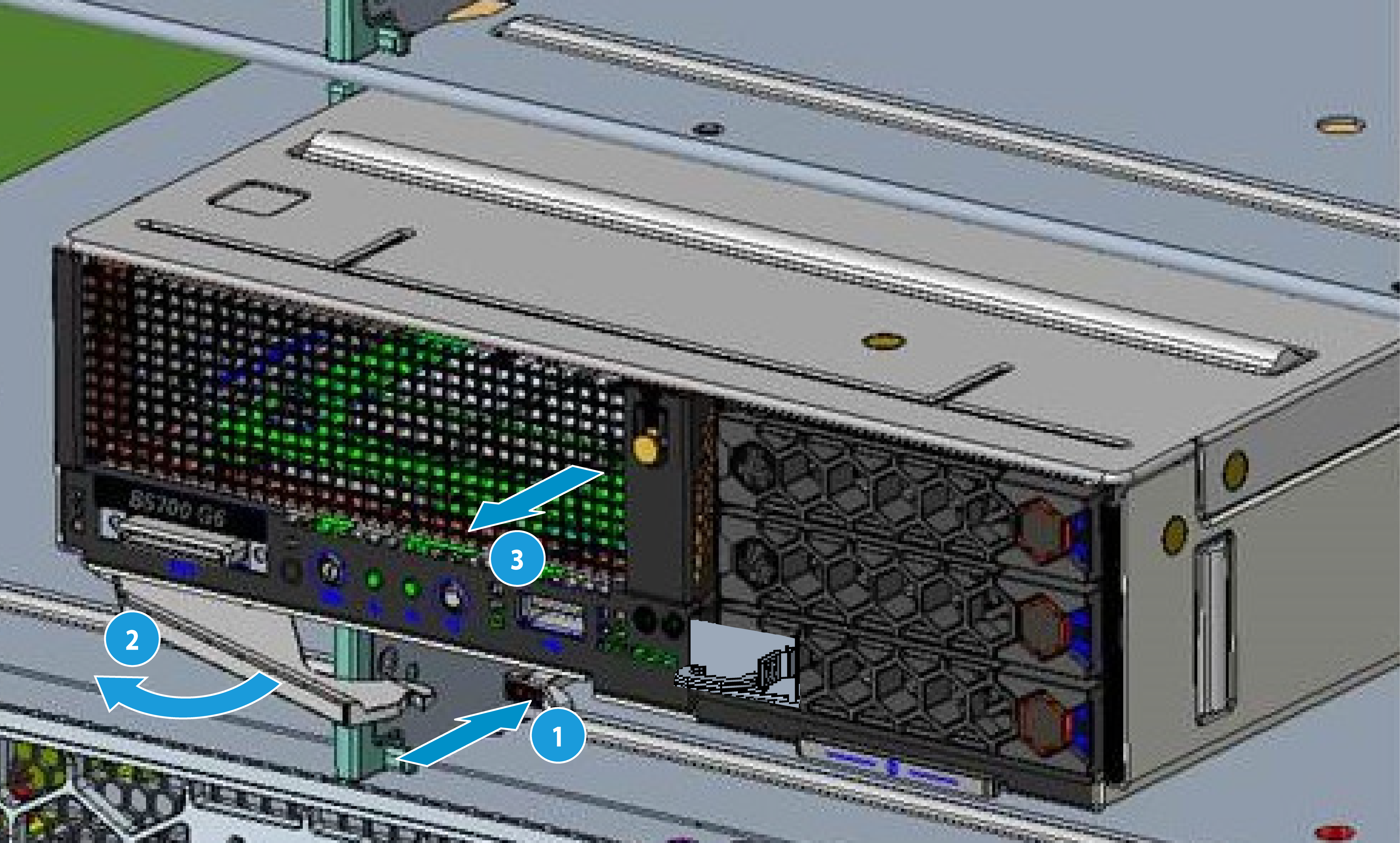
4. Remove the server from the rack.
a. As shown by callout 1 in Figure 1, press the release buttons, and the ejector levers will automatically pop open.
b. As shown by callouts 2 and 3 in Figure 1, rotate the ejector levers out to remove the server from the rack.
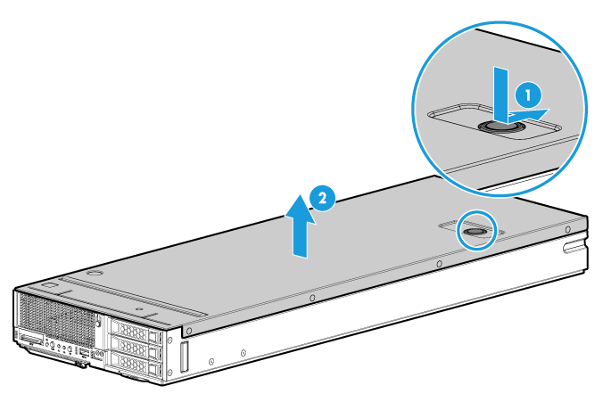
5. Remove the access panel.
a. As shown by callout 1 in Figure 2, press the release button on the access panel and slide the access panel a little towards the rear.
b. As shown by callout 2 in Figure 2, hold the two sides of the access panel and lift it away from the server.
Figure 2 Removing the access panel
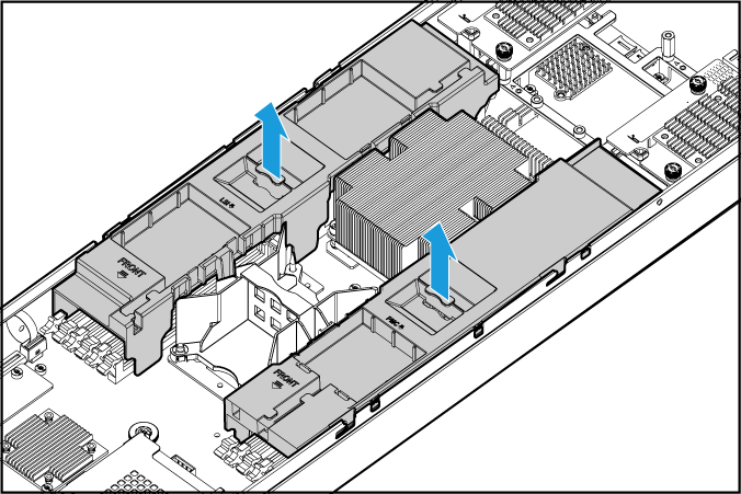
6. Remove the chassis air baffle. As shown in Figure 3, lift the chassis air baffle up and away from the chassis.
Figure 3 Removing the chassis air baffle
Installing the processor
Guidelines
· To avoid damage to the processors or system board, only H3C-authorized personnel and professional server engineers are allowed to install a processor.
· Make sure the processors are the same model if two processors are installed.
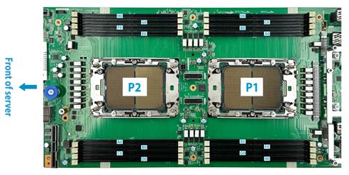
· Heatsinks with densely populated and sparsely populated fins are available for a processor. Make sure you install a heatsink with densely populated fins (marked Rear) on processor 1, and a heatsink with sparsely populated fins (marked Front) on processor 2. For information about processor socket locations, see Figure 4.
· The pins in the processor socket are very fragile. Make sure a processor blank is installed on an empty processor socket.
· For the server to operate correctly, make sure processor 1 is in position.
· To avoid ESD damage, put on an ESD wrist strap before performing this task, and make sure the wrist strap is reliably grounded.
Procedure
|
|
CAUTION: When you remove the protective cover over the heatsink, be careful not to touch the thermal grease on the heatsink. |
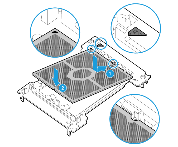
1. As shown by callout 1 in Figure 5, tilt the processor to interlock the guide slot at one end of the processor with the guide post at one end of the retaining bracket. Make sure the triangle mark on the processor aligns with the triangle mark on the retaining bracket.
2. As shown by callout 2 in Figure 5, place the CPU downwards. Make sure the guide slot at the other end of the CPU engages with the guide post at the other end of the retaining bracket.
Figure 5 Attaching a processor to a retaining bracket
Installing a retaining bracket that carries a processor to a heatsink
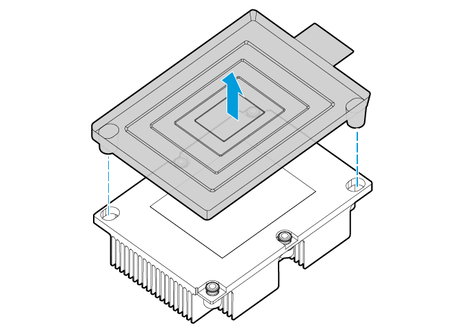
1. Remove the plastic box on the heatsink. As shown in Figure 6, lift the plastic box to remove it from the heatsink.
|
|
NOTE: When removing the plastic box, be careful not to touch the thermal grease on the heatsink. |
Figure 6 Removing the plastic box from a heatsink
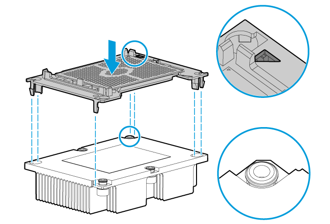
2. Install the retaining bracket that carries the processor onto the heatsink. As shown in Figure 7, align the triangle mark on the retaining bracket with the notched corner on the heatsink. Place the retaining bracket downward and press it until you hear a click, which indicates that the four corners of the retaining bracket are tightly locked with the four corners of the heatsink.
Figure 7 Installing a retaining bracket that carries a processor to a heatsink
Remove the processor blank from the processor socket in the blade server
|
|
CAUTION: · The pins in the processor socket are extremely fragile and easily damaged. To avoid replacing the system board due to pin damage, do not touch the pins. · Keep the pins in the processor socket clean and avoid dropping any debris into the processor socket. |
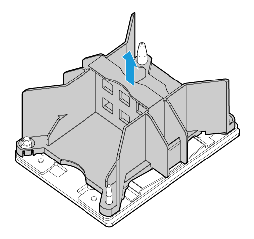
As shown in Figure 8, hold the processor bracket and lift it upward. Keep the processor bracket safe for future use.
Figure 8 Removing the processor bracket from a processor socket
Installing a heatsink that carries a processor to the blade server
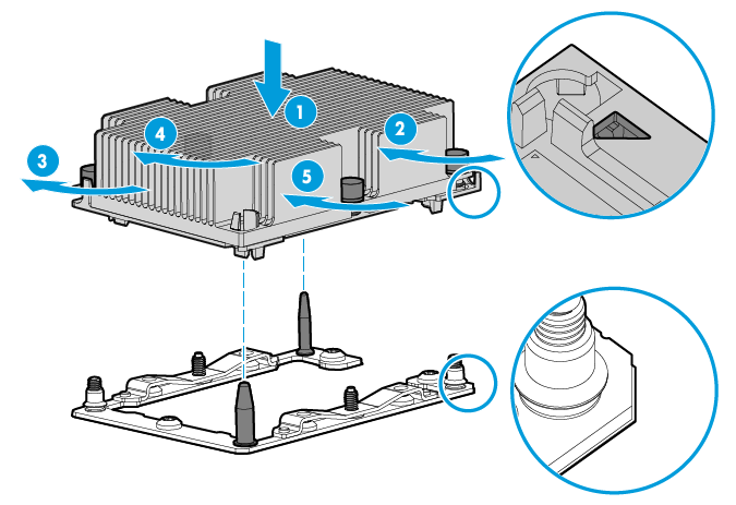
1. Align the triangle on the retaining bracket with the notched corner on the processor socket. Align the two holes on the heatsink with the two guide pins on the processor socket, and place the heatsink downwards on the processor socket, as shown by callout 1 in Figure 9.
2. Tighten the captive screws on the heatsink in sequence, following the order shown by callouts 2 to 5 in Figure 9 (the order indicated by the labels on the heatsink surface). Strictly follow this sequence to fasten the screws, as the incorrect order might cause the screws to come loose.
|
|
CAUTION: Tighten the screws with a torque of 1.4 N·m (12 in-lbs). Failure to do so might result in poor contact with the processor or damage to the pins in the processor socket. |
Figure 9 Installing the heatsink with the processor onto the blade server
Installing DIMMs
After you install a new processor, install DIMMs for it. For DIMM installation when two processors are present, see the user guide for the server.
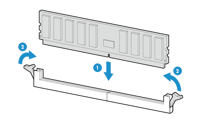
To install a DIMM:
1. Open the retaining clips of the DIMM slot.
2. Align the notch on the DIMM bottom edge with the key on the DIMM slot.
3. Insert the DIMM into the slot and make sure the retaining clips lock the DIMM in place.
The DIMM slot has a structure that prevents misalignment. If you cannot insert the DIMM into the slot easily, the installation might be wrong. Reorient the DIMM and then insert it into the slot again.
Figure 10 Installing a DIMM
Starting the server
1. Install the removed air baffles.
2. Install the access panel.
3. Install the server in the rack.
4. Connect power cords for the server.
5. Power on the server.
