- Released At: 28-04-2024
- Page Views:
- Downloads:
- Related Documents
-
H3C SecPath M9000-X NSQM7SUPA0 supervisor engine module
1 Identifier
The module identifier NSQM7SUPA0 is in the upper right corner of the front panel.
2 About the module
The NSQM7SUPA0 supervisor engine module has one console port, one copper management Ethernet port, one fiber management Ethernet port, and one USB port.
3 Specifications
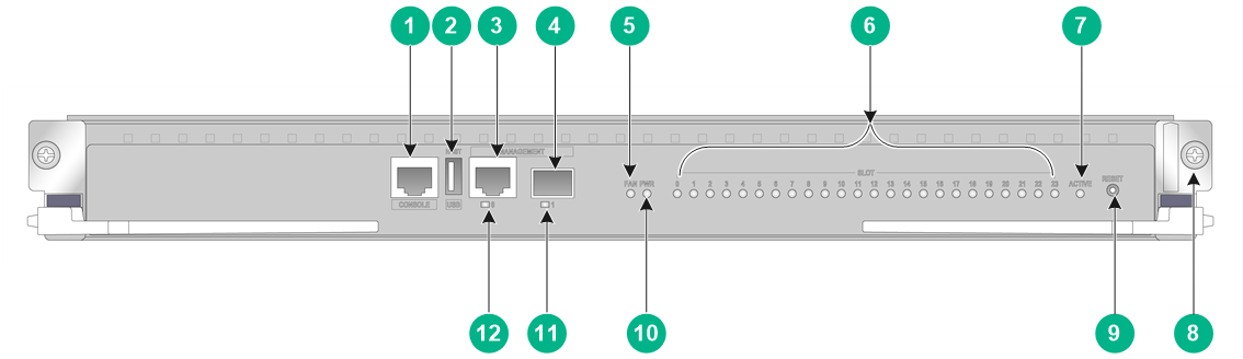
Figure 1 Front pane
|
(1) Console port |
(2) USB port |
|
(3) Copper management Ethernet port |
(4) Fiber management Ethernet port |
|
(5) Fan tray status LED (FAN) |
(6) Module status LEDs |
|
(7) Active/standby status LED (ACTIVE) |
(8) Captive screw |
|
(9) Reset button (RESET) |
(10) Power supply status LED (PWR) |
|
(11) Fiber management Ethernet port LED |
(12) Copper management Ethernet port LED |
Table 1 Module specifications
|
Item |
Specification |
|
Flash |
4 GB |
|
Memory |
8 GB (DDR3 SODIMM) |
|
Dimensions (H × W × D) |
43.7 × 433 × 512 mm (1.72 × 17.05 × 20.16 in) |
|
Power consumption |
28 W to 34 W |
|
Weight |
4 kg (8.82 lb) |
|
Hot swapping |
If two supervisor engine modules are installed on a device, you can hot swap the standby supervisor engine module. If only one supervisor engine module is installed on a device, you cannot hot swap the supervisor engine module. |
|
Ports |
· 1 × console port · 1 × GE SFP port for management and upgrade · 1 × 10/100/1000BASE-T port for management and upgrade · 1 × USB port |
|
Ambient temperature |
· Operating: 0°C to 45°C (32°F to 104°F) · Storage: –40°C to +70°C (–40°F to +158°F) |
|
Ambient humidity |
5% RH to 95% RH, noncondensing |
|
Compatible device models and slots |
M9000-X10 multiservice security gateway (slots 0 and 1) |
|
|
IMPORTANT: · The USB port outputs power as prescribed by USB 2.0. For the USB port to identify the USB device, use only a USB device fully compliant with USB 2.0. · For a correct connection between a management Ethernet port on the supervisor engine module and its peer port, configure the same data rate and duplex mode for the two ports. · To upgrade the software or BootWare from BootWare, you can only use a 10/100/1000BASE-T copper management Ethernet port to transfer the software image files. |
Table 2 Console port specifications
|
Item |
Specification |
|
Connector type |
RJ-45 |
|
Interface standard |
RS-232 |
|
Transmission baud rate |
9600 bps (default) to 115200 bps |
|
Transmission medium |
Asynchronous serial cable |
|
Transmission distance |
≤ 15 m (49.21 ft) |
|
Services |
· Provides connection to an ASCII terminal. · Provides connection to the serial port of a local PC running a terminal emulation program. · Supports the command line interface (CLI) |
Table 3 Copper management Ethernet port specifications
|
Item |
Specification |
|
Connector type |
RJ-45 |
|
Interface standard |
802.3, 802.3u, and 802.3ab |
|
Interface type |
MDI/MDIX autosensing |
|
Transmission medium |
Category-5 twisted pair cable |
|
Transmission distance |
100 m (328.08 ft) |
|
Transmission rate and duplex mode |
· 10 Mbps, half/full duplex · 100 Mbps, half/full duplex · 1000 Mbps, full duplex |
Table 4 Fiber management Ethernet port specifications
|
Item |
Specification |
|
Connector type |
· LC · RJ-45 |
|
Transceiver medium and maximum transmission distance |
SFP transceiver modules: see Table 5. |
|
Interface standard |
802.3, 802.3u, and 802.3ab |
|
Transmission rate and duplex mode |
1000 Mbps, full duplex |
Table 5 SFP transceiver modules available for the fiber management Ethernet ports
|
Module |
Central wavelength |
Connector type |
Cable specifications |
Maximum transmission distance |
|
SFP-GE-T |
N/A |
RJ45 |
Category-5 (or above) twisted pair cable |
100 m (328.08 ft) |
|
SFP-GE-T-D |
N/A |
RJ-45 |
Category-5 (or above) twisted pair cable |
100 m (328.08 ft) |
|
SFP-GE-SX-MM850-A |
850 nm |
LC |
50/125 µm, MMF |
550 m (1804.46 ft) |
|
62.5/125 µm, MMF |
275 m (902.23 ft) |
|||
|
SFP-GE-LX-SM1310-A |
1310 nm |
LC |
9/125 µm, SMF |
10 km (6.21 miles) |
|
SFP-GE-LH40-SM1310 |
1310 nm |
LC |
9/125 µm, SMF |
40 km (24.86 miles) |
|
SFP-GE-LH40-SM1550 |
1550 nm |
LC |
9/125 µm, SMF |
40 km (24.86 miles) |
|
SFP-GE-LH80-SM1550 |
1550 nm |
LC |
9/125 µm, SMF |
80 km (49.71 miles) |
|
SFP-GE-LH100-SM1550 |
1550 nm |
LC |
9/125 µm, SMF |
100 km (62.13 miles) |
|
SFP-GE-SX-MM850-D |
50 nm |
LC |
50/125 µm, MMF |
550 m (1804.46 ft) |
|
850 nm |
LC |
62.5/125 µm, MMF |
275 m (902.23 ft) |
|
|
SFP-GE-SX-MM850-D |
850 nm |
LC |
50/125 µm, MMF |
100 m (328.08 ft) |
4 LEDs
Table 6 LED description
|
LED |
Status |
Description |
|
Copper management Ethernet port LED/Fiber management Ethernet port LED |
Flashing |
A link is present on the port and the port is sending or receiving data. |
|
On |
A link is present on the port. |
|
|
Off |
No link is present on the port. |
|
|
Power supply status LED (PWR) |
Steady green |
All the power supplies are operating correctly. |
|
Steady red |
One or more power supplies are faulty. |
|
|
Off |
No power is present on the device. |
|
|
FAN tray status LED (FAN) |
Steady green |
All the fan trays are operating correctly. |
|
Steady red |
A fan tray is faulty, or no fan tray is present in the device. |
|
|
Off |
No power is present on the device. |
|
|
Module status LED (SLOT) |
Flashing (0.5 Hz) |
The module in the slot is operating correctly. |
|
Flashing (4 Hz) |
The module in the slot is loading software. If the LED remains in this state, the module software is not compatible with the device software. |
|
|
Steady green |
The module in the slot is starting up. |
|
|
Steady red |
A critical alarm or fault has occurred on the module in the slot. |
|
|
Flashing red (0.25 Hz) |
The temperature of the module in the slot is higher than high-temperature warning threshold or lower than the low-temperature alarm threshold. |
|
|
Off |
No module is in the slot, or the module in the slot is faulty. |
|
|
Active/standby status LED |
On |
The supervisor engine module is operating in active state. |
|
Off |
· The supervisor engine module is operating in standby state. · The supervisor engine module is faulty. (You can examine also the status LED for the supervisor engine module to determine whether a fault has occurred.) |
5 Obtaining documentation
For information about installing the supervision engine module, see the installation guide for the device.
Copyright © 2021 New H3C Technologies Co., Ltd.
The information in this document is subject to change without notice.
