- Released At: 25-07-2024
- Page Views:
- Downloads:
- Table of Contents
- Related Documents
-
H3C SecBlade FW [IPS][ADE] Module
Best Practice (V7)
Copyright © 2024 H3C Technologies Co., Ltd. All rights reserved, retaining all rights.
No part of this manual may be reproduced or transmitted in any form or by any means without prior written consent of New H3C Technologies Co., Ltd.
Except for the trademarks of New H3C Technologies Co., Ltd., any trademarks that may be mentioned in this document are the property of their respective owners.
The information in this document is subject to change without notice.
Contents
SecBlade module deployment overview
Introduction to SecBlade module deployment
SecBlade module hardware installation
SecBlade module first-time login
Technologies involved in SecBlade module deployment
SecBlade module operating mode
SecBlade module deployment solutions
SecBlade module standalone deployment overview
Side-mounted deployment Layer 3 diversion
Layer 3 direct route deployment (division of VRF)
Layer 3 straight path deployment (partitioning VLAN)
Layer 2 diversion in side-mounted deployment
Transparent direct route deployment
Attach and deploy mirroring to divert the stream
Overview of primary and secondary SecBlade module
Implementing a side-mounted primary-secondary deployment in Layer 3 traffic diversion
Layer 3 primary and backup deployment with VRF partitioning
Layer 3 primary and backup deployment (dividing VLAN) for direct routes
Side-mounted primary and secondary deployment of Layer 2 diversion
Transparent main and standby deployment in a direct path
SecBlade module dual-master deployment overview
Side-mounted dual-master deployment, directing traffic at Layer 3
Dual-primary deployment of Layer 3 direct route (dividing VRF)
Dual-master deployment of Layer 3 direct route (VLAN partitioning)
Deploy a side-mounted dual-master setup with Layer 2 stream diversion
Transparent dual-master deployment with direct path
Example of standalone deployment configuration for SecBlade module
Side-mounted deployment of SecBlade module for Layer 3 traffic diversion
Deploy SecBlade module (partition VRF) in a Layer 3 direct path deployment.
Deploy SecBlade module in Layer 3 direct route (divide VLAN)
Deploy the SecBlade module in a side-mounted configuration for Layer 2 diversion
Deploy SecBlade module in a transparent straight path deployment
SecBlade module is deployed in a side-mounted architecture for port mirroring
Example of primary and backup deployment of SecBlade module
SecBlade module deployment as a side-mounted primary and backup, diverting traffic at Layer 3
SecBlade module deployment in a main/backup mode on Layer 3 direct route with VLANs
Transparent primary and secondary direct path SecBlade module deployment
Example of deploying dual-master SecBlade module
Side-mounted dual-master deployment of SecBlade module with Layer 3 diversion.
Layer 3 direct route dual-master deployment of SecBlade module (partitioning VRF)
SecBlade module deployment in a dual-primary manner on a Layer 3 direct path (dividing VLAN)
Network configuration requirement
Deploy dual-master SecBlade module in a side-mounted configuration for Layer 2 traffic diversion
Dual primary deployment of transparent direct path SecBlade module
Network configuration requirements
SecBlade module deployment overview
Introduction to SecBlade module deployment
SecBlade module form
The SecBlade module is a security product in the form of a single board, which includes firewall, IPS, ADE, and other types of security cards. It can be used in H3C switches or routers, offering security capabilities such as attack detection, virus protection, content filtering, content identification, URL filtering, and attack prevention to devices without built-in security functions. The SecBlade module communicates with the device it's inserted into through an inline Ethernet interface on the board. To manage the SecBlade module, you must use the serial or management (Mgmt) port on the SecBlade panel. The device where the SecBlade module is located cannot manage it; they are considered two separate devices in terms of logic.
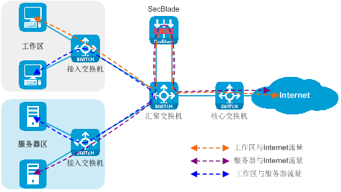
The actual effect of deploying the SecBlade module on a switch or router is shown in the figure below.
Figure 1 SecBlade module deployment

The traffic flow when the SecBlade module provides security functions for the existing network is depicted in the following illustration.
Figure 2 Network diagram of Service Traffic Deployment with SecBlade module Insertion
SecBlade module hardware installation
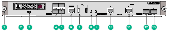
For instance, the SecBlade module hardware is installed using the LSQM2FWDSC0 card. This card integrates firewall, VPN, content filtering, content identification, URL filtering, and NAT address translation functions, among others. Without altering the network topology, installing the LSQM2FWDSC0 card on the switch can boost its security protection capabilities, providing users comprehensive and reliable security. The LSQM2FWDSC0 card has one Console interface, two USB interfaces, two pairs of Gigabit Combo interfaces, four 10GBASE-R optic interfaces, and a hard disk slot.
Figure 3 Front panel of the LSQM2FWDSC0 card insertion
|
(1) Captive screw |
(2) Wrench |
|
(3) Hard disk (HD) slot |
(4) 10GBASE-R optical interface |
|
(5) 10GBASE-R Optical Interface Indication Light |
(6) Console Interface (CONSOLE) |
|
(7) USB Interface |
(8) Hard Disk Indicator Light (HD) |
|
(9) The system's active indicator light (SYS). |
(10) Combo electrical interface (10/100/1000BASE-T) |
|
(11) Combo Interface Indicator Light (LINK/ACT) |
(12) Combo Optical Interface (1000BASE-X) |
|
(13) Combo Optical Interface Indicator Light (LINK/ACT) |
|
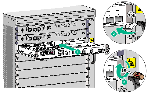
Please follow the steps below to complete the installation of the LSQM2FWDSC0 card:
· Wear the ESD wrist strap, ensuring that it is correctly connected to the earth ground.
· The operator is facing the front panel of the device, removing the service board filler panel on the target slot.
· Place the LSQM2FWDSC0 card horizontally with the device side facing up. Open the wrench and smoothly insert the LSQM2FWDSC0 card into the slot along the slot guide rails.
· Fold the wrench inward, to ensure that the LSQM2FWDSC0 card is in close contact with the backplane.
· Tighten the captive screw on the LSQM2FWDSC0 card in a clockwise direction using a Phillips screwdriver.
Figure 4 Install the LSQM2FWDSC0 card
SecBlade module first-time login
Log in to the device through the Web interface
Before leaving the factory, the device has been configured with the management (Mgmt) IP address of 192.168.0.1/24 and set up with default Web login information. Users can directly use this default information to log into the Web interface. Please refer to the table below for the default Web login information.
|
Login Information Item |
Default configuration |
|
Username |
admin |
|
Password |
admin |
|
IP address of the management port. |
192.168.0.1/24 |
· Connecting device and PC:
Connect the Ethernet management port of the PC and the device using an Ethernet cable.
· Configure the IP address for the PC to ensure it can interact with the device.
Change the IP address to any address within the 192.168.0.0/24 subnet (excluding 192.168.0.1), for example, 192.168.0.2.
· Launch the browser and enter the login information.
Launch the browser on your PC, enter the IP address "192.168.0.1" in the address bar, and press the carriage return (CR) key to access the device's Web login page. Enter the default user name and password for the device and click the <Login> button to sign in.
|
|
IMPORTANT: · Users can log in for the first time on the Web interface using the default account or by creating a new Web login account through the command line. · Once you've logged in with the default account, for the sake of device security, it's recommended to immediately change the default login cipher OR create a new administrator account and delete the default device account. |
Log in to the device through the console port
When setting up a local configuration environment through the Console port, a connection with the device needs to be established through a terminal emulation program like hyper terminal or PuTTY. Users can run these programs to connect to network devices, Telnet or SSH sites. For a detailed introduction and instructions on how to use these programs, please refer to the user guide of the program.
Upon their initial login to the device, users can access via the Console port. During login, the default authentication method is scheme (the username and password are 'admin').
After opening the terminal emulation program, please set the terminal parameters according to the following requirements:
· Baud Rate: 9600
· Data Bits: 8
· Stop bit: 1
· Parity Check: None
· Traffic control: None
Log in to the device through Telnet
The steps to log into the device through Telnet are as follows:
· Connect to the device using the Console port, and enable the Telnet function by using the 'telnet server enable' command under the system view.
· Under the VTY subscriber line view, configure the authentication method, user role and common properties for the user. By default, the authentication method is scheme, the username is admin, and the cipher is admin.
· Before the device leaves the factory, the IP address of the management (Mgmt) port has been set to 192.168.0.1/24. Users need to configure the IP address of the PC port, ensuring that the route between the device and the user's PC is reachable.
· Run the Telnet client on the PC, and after entering the default login information, you can then access the device.
For detailed instructions on how to access the device, please refer to the configuration guide and command reference included with the device.
Technologies involved in SecBlade module deployment
Deploying the SecBlade module involves the following technical aspects:
· VLAN: VLAN (Virtual Local Area Network) technology divides a physical LAN into multiple logical LANs - VLANs. Hosts in the same VLAN can directly communicate with each other, while hosts in different VLANs cannot.
· Cross-VLAN Mode Bridge Forwarding: Cross-VLAN mode bridge forwarding is a technical method completed at the data link layer (DDL) that allows communication between different VLANs. This technology enables two different VLANs to achieve layer-two intercommunication.
· QoS Traffic Redirect: QoS traffic redirect is the technology of redirecting traffic that meets the traffic classification criteria to other locations for processing. Based on different traffic classifications, the required traffic can be flexibly selected for redirection.
· VPN Tech: A VPN-instance, also known as a VRF (Virtual Routing and Forwarding) instance, is utilized for the isolation of routes between different VPNs. Each VPN-instance maintains a relatively independent routing table and LFIB (Label Forwarding Information Base) to ensure the independence and security of VPN data.
· Policy Routing: Policy routing is a technology that carries out route forwarding according to the policies set by users. Policy routing can execute specific operations (such as setting the packet's next hop, egress interface, SRv6 TE Policy, default next hop, default egress interface, and default SRv6 TE Policy, etc.) for packets that meet certain conditions (like ACL rules, packet length, etc.).
· Mirroring: Port mirroring is a technical way that copies packets from designated ports, VLAN or CPU to a port connected to a data monitoring device. It allows users to analyze these duplicated packets with the device, facilitating network monitoring and fault troubleshooting.
· Dual-Hot Standby (RBM): Dual-Hot Standby (RBM) is a technology that achieves high availability (HA) at the device level through our company's proprietary RBM (Remote Backup Management) protocol. This technical approach can provide alternative solutions when a communications line or device experiences a fault. If a network node (NN) fails, another network node can take over the faulty node's tasks and continue working.
Traffic diversion methods
In order to enable the security function of the SecBlade module, it is necessary to first introduce the service traffic to the SecBlade module, ensuring data connectivity between the switch/router and the SecBlade module. There are several traffic diversion methods for switches/routers as follows:
· Policy routing diversion: The upstream and downstream interfaces on the switch/router operate at layer three. Configuring policy routing sets the next hop of the message to the SecBlade module, thereby routing the incoming and outgoing traffic to the SecBlade module.
· Divide VRF for isolation and implement Layer 3 switch's downstream interface and upstream interface work on Layer 3 and are divided into different VRFs. The diversion port and service port are divided into the same VRF. Configure static route to set the next hop of the packet to the SecBlade module, introducing upstream and downstream traffic to the SecBlade module.
· QoS Policy Traffic Diversion: The upstream and downstream interfaces on the switch/router operate at stratum two and are divided into the same VLAN. By configuring the QoS policy, traffic is redirected to the SecBlade module, achieving the diversion of upstream and downstream traffic into the SecBlade module.
· Divide VLAN isolation, Layer 2 diversion: The upstream and downstream interfaces on the switch/router work at Layer 2 and are divided into different VLANs. The diversion port and service port are divided into the same VLAN. The same VLAN Layer 2 is interconnected, realizing the introduction of upstream and downstream traffic into the SecBlade module.
· Port Mirroring Traffic Diversion: The upstream and downstream interfaces on the switch/router can work at both Layer 2 and Layer 3 (but need to be consistent with the mirrored interface type). The switch/router configures port mirroring to duplicate upstream and downstream traffic to the SecBlade module.
SecBlade module operating mode
After processing security tasks, the SecBlade module needs to re-inject the received packets to the switch/router OR discard them. The handling method of packets is determined by the working mode of the SecBlade module. There are several working modes supported by the SecBlade module:
· Routing Mode: In SecBlade module, the service port operates at Layer 3, and packets are forwarded by looking up the routing table.
· Transparent mode: In this mode, the SecBlade module operates at the Layer 2. It checks the MAC address table and forwards packets accordingly.
· In Cross-VLAN mode Bridge: the SecBlade module service port operates at the Layer 2. It forwards messages by checking the MAC address table and then, via the Cross-VLAN mode Bridge, it translates the VLAN of the uplink and downlink messages.
· Black Hole Mode: The SecBlade module's service port operates in Layer 2 or Layer 3. After processing the security service, the message is discarded.
SecBlade module backup mode
The SecBlade module can be deployed in one or two units, depending on the number and method of deployment. The SecBlade module has the following backup modes:
· Standalone deployment: Only one machine is deployed, and the SecBlade module does not have a backup.
· Primary and Secondary Deployment: Two devices are deployed. The SecBlade module in the primary device processes operations while the secondary device serves as a backup. If the link or overall system of the primary device encounters a fault, the backup can take over, ensuring service continuity.
· Dual-Master Deployment: It involves the deployment of two devices, with both of these SecBlade module-based devices processing traffic. If a device experiences a link or overall system fault, the other device can take over, ensuring the traffic is not disrupted.
SecBlade module deployment solutions
Based on the working mode of the SecBlade module, the backup mode, and the differing methods of stream diversion in switches OR routers, there are several typical deployment strategies. These can be chosen according to actual application situations.
Table 1 SecBlade module deployment solutions
|
SecBlade module deployment solution |
Traffic diversion method |
SecBlade module operating mode |
SecBlade module backup mode |
|
Layer 3 diversion is deployed on the side. |
The policy routing is diverting traffic. |
Route Mode |
Single-node deployment |
|
Layer 3 direct route deployment (dividing VRF) |
Segment VRF for isolation, divert traffic at Layer 3. |
Routing mode |
Single-node deployment |
|
Layer 3 direct route deployment (partitioning VLAN) |
Divide and isolate VLAN, implement layer two traffic diversion. |
Route mode |
Single-node deployment |
|
Implement a secondary stratum diversion by deploying it on the side. |
QoS Policy Diversion |
Transparency Mode |
Single-node deployment |
|
Transparent Direct Deployment |
Translate the VLAN to ensure isolation, and divert at Layer 2. |
Cross VLAN Mode Bridge |
Single-node deployment |
|
Attach and deploy mirroring for traffic diversion. |
Port mirroring for stream diversion. |
Black Hole Mode |
Single-node deployment |
|
Deploy the master-backup on the side and divert the Layer 3 stream. |
The implementation of policy routing for traffic diversion. |
Route Mode |
Primary and secondary deployment |
|
Layer 3 primary and secondary deployment (dividing VRF) in a straight path. |
Divide VRF isolation, Layer 3 guides the flow. |
Route mode |
Primary-secondary deployment |
|
Layer 3 primary and secondary deployment with straight-through routing (dividing VLANs) |
Divide VLAN for isolation, and use layer 2 for stream diversion. |
Route Mode |
Primary-Secondary Deployment |
|
Side-mounted primary and backup deployment with a two-layer stream diversion. |
QoS policy stream diversion |
Transparency Mode |
Primary-Secondary Deployment |
|
Transparency direct-route primary and backup deployment. |
Divide VLAN isolation and implement Layer 2 traffic steering. |
Bridge mode across VLAN. |
Primary-standby deployment |
|
Side-mounted dual-master deployment with three-level stream diversion. |
Policy-based routing |
Route Mode |
Dual-master deployment |
|
Dual-master deployment of a Layer 3ed direct road (dividing VRF). |
Partition VRF isolation and use Layer 3 diversion. |
Route Mode |
Dual-Master Deployment |
|
Dual-master deployment of Layer 3 direct road (VLAN partitioning) |
Divide VLAN isolation, and use Layer 2 traffic steering. |
Route Mode |
Dual-principal deployment |
|
Side-mounted dual-master deployment for a two-layer stream diversion. |
QoS policy guides the stream. |
Transparent Mode |
Dual master deployment |
|
Transparent Dual-Master Deployment with Direct Connection |
Divide VLAN isolation, and perform Layer 2 traffic steering. |
Cross-VLAN Mode Bridge |
Dual-Master Deployment |
|
|
NOTE: · When deploying the SecBlade module with three inline ports in either standby or dual-primary mode, it's necessary to use the inline port as the HA channel for RBM. · When deploying the SecBlade module with two internal ports for primary/backup OR dual-primary configuration, it is necessary to use the panel ports as the RBM HA channel. · When deploying a SecBlade module with a single internal link port at Layer 3, it is necessary to divide the subinterface. It does not support the deployment of side-mounted two-layer diversion when deployed at the Layer 2. It does not support main-backup and dual-master deployment. |
SecBlade module standalone deployment overview
Side-mounted deployment Layer 3 diversion
Side-mounted deployment of a Layer 3 diversion is a Layer 3 SecBlade module deployment method, in which the router uses policy routing for traffic diversion, and the SecBlade module operates in routing mode. This deployment method is generally used in scenarios where upstream and downstream network segments are different, and there is no desire to change the existing network topology.
As shown in the figure below, the SecBlade module is installed in slot 2 of the router, and it is necessary to conduct security checks on the traffic between the Host and the Internet. The two networks are in different network segments, with the router functioning as their GW.
Figure 5 Side-mounted deployment diagram of the Layer 3 diversion logic
The working method of sideload deployment tri-stratum diversion:
· The uplink and downlink interfaces on the router are divided into different network segments. Through configuring policy routing, the next hop of the uplink and downlink traffic is directed towards the SecBlade module.
· The SecBlade module interface operates at Layer 3, forwarding messages by checking the routing table.
· After the router receives the traffic feedback from the SecBlade module, it forwards it to the upstream and downstream devices at Layer 3.
The pros and cons of deploying a sidecar Layer 3 diversion strategy:
· Advantages: No need to change the existing network topology during deployment, enabling faster deployment of SecBlade modules. It allows selective traffic diversion for services requiring security functions while other traffic continues to follow the original path. The system supports a wide range of routing and security features, such as OSPF, NAT, LB, SecPolicy, and DPI.
· Disadvantages: The load diversion policy is complex, increasing maintenance difficulty, and cannot be used simultaneously with the fast forwarding load sharing function.
Layer 3 direct route deployment (division of VRF)
The Layer 3 direct routing deployment (VRF partitioning) is a form of Layer 3 SecBlade module deployment. In this deployment method, the router employs VRF partitioning for Layer 3 traffic diversion, and the SecBlade module operates in routing mode. This deployment method is generally used in scenarios where upstream and downstream network segments are different and the original network configuration can be modified.
As shown in the figure below, the SecBlade module is installed in slot 2 of the router, which needs to perform security detection on the traffic between the Host and the Internet. The two networks are in different network segments, and the router serves as their gateway (GW).
Figure 6 Layer 3 direct route deployment (dividing VRF) logic diagram
The working method of Layer 3 straight path deployment (dividing VRF):
· The router's upstream and downstream interfaces operate at Layer 3 and are divided into different VRFs. The drain port and service port are divided into the same VRF. The upstream and downstream traffic is directed to the SecBlade module through a static route.
· The SecBlade module operates at Layer 3, forwarding packets by checking the routing table.
· After receiving the traffic backflow from SecBlade module insertion, the router forwards it to the upstream and downstream devices at Layer 3.
The advantages and disadvantages of a Layer 3 direct route deployment (dividing VRF):
· Advantages: There's no need to configure and maintain complex policy routing. It supports a variety of route and security functions, such as OSPF, NAT, LB, SecPolicy, and DPI, etc.
· Disadvantage: Additional network address planning is required, and the existing network topology needs to be changed during deployment.
Layer 3 straight path deployment (partitioning VLAN)
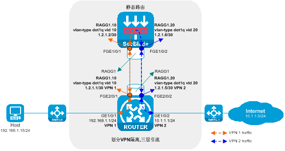
Layer 3 bypass deployment (dividing VLAN) is a type of layer 3 SecBlade module deployment method. In this method, the switch performs layer 2 diversion after dividing VLANs, and the SecBlade module operates in routing mode. This deployment method is generally used in scenarios where upstream and downstream are in different network segments and different VLANs.
As shown in the following diagram, the SecBlade module is installed in slot 2 of the switch and needs to perform security checks on the traffic between the Host and the Internet. The two networks are in different network segments, with the SecBlade module serving as their gateway.
Figure 7 Layer 3 straight-path deployment (dividing VLAN) logic diagram
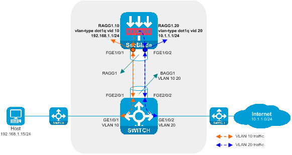
Working method of Layer 3 direct deployment (VLAN division):
· The upstream and downstream interfaces on the switch work at Layer 2 and are divided into different VLANs. The diversion port and service port are assigned to the same VLAN, allowing Layer 2 communication within the same VLAN, and achieving the introduction of upstream and downstream traffic to the SecBlade {card}.
· The SecBlade module interface operates at Layer 3, forwarding packets by looking up the routing table.
· After the switch receives the traffic backnote from the SecBlade module, it forwards it to upstream and downstream devices at Layer 2.
The pros and cons of deploying a Layer 3 direct path (dividing VLAN):
· Advantages: No need to configure and maintain complex policy routing, it supports a wide range of routing and security features, such as OSPF, NAT, LB, SecPolicy, and DPI etc.
· Disadvantage: Extra planning for network addresses is required, and existing network topology needs to be altered during deployment.
Layer 2 diversion in side-mounted deployment
The side-mounted, Layer 2 diversion deployment is a method of deployment for the SecBlade module, whereby the switch utilizes a QoS policy for the stream diversion and the SecBlade module operates in transparency mode. This deployment method is generally employed in scenarios where upstream and downstream are on the same network segment, the same VLAN, and there is no desire to alter the existing group network.
As shown in the figure below, the SecBlade module is installed in the second slot of the switch and needs to perform security checks for the traffic of VLAN10. VLAN10 is in the same network segment.
Figure 8 Attachment deployment diagram of the Layer 2 diversion logic
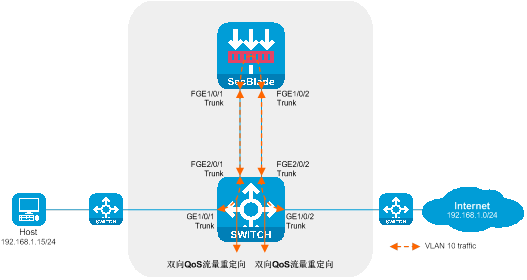
The working method of side-mounted deployment and Layer 2 diversion:
· On the switch, the upstream and downstream interfaces are divided into the same VLAN, redirecting traffic to the SecBlade module through the QoS policy.
· The SecBlade module interface operates at the Layer 2, forwarding packets by checking the MAC address table.
· After receiving the return traffic from the SecBlade module insertion, the switch redirects the traffic to upstream and downstream devices through QoS policy.
Pros and cons of sidecar deployment streaming at the Layer 2:
· Advantages: No need to alter the existing network topology when deploying, allows faster deployment of SecBlade module, only the service requiring security function processing needs to divert, and the rest of the traffic is forwarded according to the original path.
· Drawbacks: The drainage policy is complex, increasing the difficulty of maintenance. It does not support routing functions and only supports a limited number of security features.
Transparent direct route deployment
Transparent straight-through deployment is a type of Layer 2 SecBlade module deployment method. In this deployment, the switch employs VLAN diverting, and the SecBlade module operates in a cross-VLAN mode, known as Bridge. This deployment method is typically used in scenarios where upstream and downstream are on the same network segment but with different VLANs.
As shown in the diagram below, the SecBlade module is installed in slot 2 of the switch and needs to perform security checks on the traffic between the Host and the Internet. The two networks are on the same network segment.
Figure 9 Transparency direct route deployment logic diagram
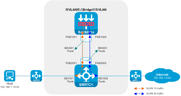
Working mode of the transparent straight-through deployment:
· The upstream and downstream interfaces of the switch work at Layer 2 and are divided into different VLANs. The flow diversion port and service port are assigned to the same VLAN, allowing layer 2 communication within the same VLAN. This enables the upstream and downstream traffic to be directed into the SecBlade module.
· The SecBlade module interface operates at Layer 2, forwarding packets by looking up the MAC address table, and translating the VLAN of uplink and downlink packets using cross-VLAN mode Bridge.
· After receiving the return traffic from the SecBlade module, the switch forwards it to the upstream and downstream devices at the Layer 2.
The pros and cons of deployment straight-through in transparency:
· Advantages: The configuration logic is simple, without the need for complex QoS policy traffic diversion settings, fault handling is straightforward, and it is possible to only divert traffic that requires security processing, while other traffic continues to be forwarded along the original path.
· Drawbacks: Does not support routing function, only supports a limited number of security functions, requires changes to the existing network topology during deployment, a single service needs two VLANs for deployment, resulting in the number of supported services being halved.
Attach and deploy mirroring to divert the stream
Side-mounted deployment with mirrored traffic diversion is a Layer 2/3 supported SecBlade module deployment method. In this deployment method, the switch uses port mirroring to divert traffic, and the SecBlade module operates in black hole mode. This deployment method is generally used in scenarios where only audit is required for upstream and downstream traffic, and no blocking is necessary.
As shown in the diagram below, the SecBlade module is installed in slot 2 of the switch, and it is necessary to audit the upstream and downstream traffic.
Figure 10 Network diagram
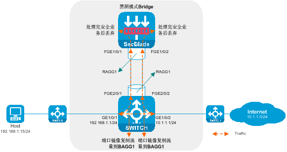
Attached deployment mirroring for workload diversion: The working method involves deploying a mirrored setup parallel to the main operation and diverting the flow to it.
· On the router, the uplink and downlink service path remains unchanged. Traffic is duplicated through port mirroring and sent to the SecBlade module.
· The SecBlade module interface operates at Layer 2/3 (with Layer 3 as an example here). After processing the security service for the message, it is discarded.
Pros and cons of side-mounted deployment mirroring for traffic diversion:
· Advantages: During deployment, there is no need to change the existing network topology, which allows for a quicker installation of the SecBlade module.
· Downside: It lacks the capability to block suspicious traffic and only supports a few security functions.
Overview of primary and secondary SecBlade module
Implementing a side-mounted primary-secondary deployment in Layer 3 traffic diversion
Side-hanging primary and backup deployment with Layer 3 diversion is a Layer 3 SecBlade module deployment method. In this deployment, the router uses policy routing for traffic diversion, the SecBlade module operates in routing mode, and the SecBlade module backup mode is primary and backup mode. This deployment method is generally used in scenarios where upstream and downstream network segments are different and there is no desire to change the existing network group setup.
As shown in the diagram below, two SecBlade modules are installed in the second and third slots of the router, and it is necessary to perform security checks on the traffic between the Host and the Internet. The two networks are in different network segments, and the router serves as their gateway.
Figure 11 Side-by-side Primary and Backup Deployment of Layer 3 Diversion Logic Diagram
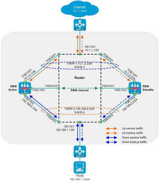
The working method of side-hanging primary-secondary deployment and three-stratum diversion:
· The router's upstream and downstream interfaces are divided into different network segments. By configuring policy routing, the next hop of the upstream and downstream traffic is directed to the SecBlade module.
· The router processes service through the preferred main SecBlade module via VRRP.
· The SecBlade module interface works at layer 3, and packets are forwarded by checking the routing table.
· The SecBlade module passes through RBM to implement primary and secondary backups with VRRP.
· After the router receives the traffic feedback from the SecBlade module, it forwards it to the upstream and downstream devices at Layer 3.
Advantages and disadvantages of deploying the active-standby mode on the side and draining the three-level stream:
· Advantages: There is no need to change the existing network topology during deployment, which allows for faster SecBlade module implementation. It can selectively divert traffic for services requiring security functions, while other traffic continues to be forwarded according to the original path. It supports a wide range of routing and security features, such as OSPF, NAT, LB, SecPolicy, and DPI.
· Disadvantage: The drainage policy is complex, increasing the maintenance difficulty, and cannot be used simultaneously with the fast forwarding load sharing function.
Layer 3 primary and backup deployment with VRF partitioning
The Layer 3 direct routing primary and backup deployment (dividing VRF) is a method of deploying the Layer 3 SecBlade module. In this method, the router uses divided VRF isolation for Layer 3 traffic diversion, and the working mode of the SecBlade module is the router mode, while its backup mode is the primary-secondary mode. This deployment approach is generally used in scenarios where the upstream and downstream network segments differ and the original network organization can be changed.
As shown in the diagram below, two SecBlade modules are installed in slots 2 and 3 of the router for security checks on traffic between the Host and the Internet. These two networks are on different network segments, with the router acting as their gateway.
Figure 12 Primary and secondary deployment diagram of the Layer 3 straight road (dividing VRF) logic schema
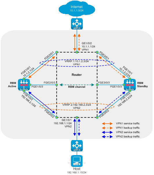
The working mode of the Layer 3 direct path master-standby deployment (dividing VRF):
· The upstream and downstream interfaces on the router work at Layer 3 and are divided into different VRFs. The diversion ports and service ports are in the same VRF, and the upstream and downstream traffic is directed to the SecBlade module via static routes.
· The router processes service using the preferred primary SecBlade module through VRRP.
· The SecBlade module works at Layer 3, forwarding packets by referencing the routing table.
· SecBlade module achieves primary and backup redundancy through RBM linkage with VRRP.
· After receiving the return traffic from the SecBlade module, the router forwards it to the upstream and downstream devices at Layer 3.
The advantages and disadvantages of the primary and backup deployment of Layer 3 straight roads (dividing VRF):
· Advantages: Supports a wide range of routing and security features, such as OSPF, NAT, LB, SecPolicy, and DPI, without the need for configuration and maintenance of complex policy routing.
· Drawbacks: Extra planning for network addresses is needed, and existing network topology must be altered during deployment.
Layer 3 primary and backup deployment (dividing VLAN) for direct routes
The Layer 3 direct route primary-standby deployment (divided into VLANs) is a deployment method of the Layer 3 SecBlade module. In this deployment method, the switch uses Layer 2 stream diversion after dividing VLANs, and the working mode of the SecBlade module is the routing mode. The backup mode of the SecBlade module is the primary-standby mode. This deployment method is generally used in scenarios where the upstream and downstream have different network segments and different VLANs.
As shown in the diagram below, two SecBlade modules are installed in the slot 2 and slot 3 of the switch, which are required to conduct security checks on the traffic between the Host and the Internet. These two networks are located in different network segments, with the SecBlade modules acting as their gateway.
Figure 13 The logic diagram of the Layer 3 main and backup deployment (division of VLAN)
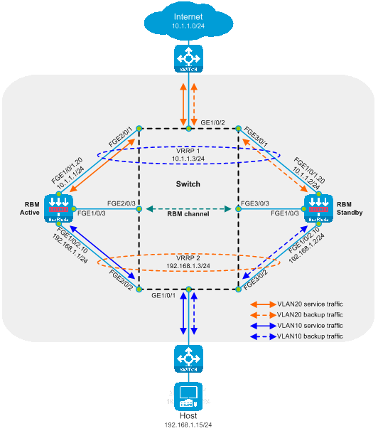
The working mode of the Layer 3 direct route primary and backup deployment (dividing VLAN):
· The upstream and downstream interfaces of the switch work at the Layer 2 and are divided into different VLANs. By allocating the diversion port and the service port into the same VLAN, which allows communication at the Layer 2 within the same VLAN, the upstream and downstream traffic is directed to the SecBlade module.
· The uplink and downlink devices handle service operations through the preferred main SecBlade module via VRRP.
· The SecBlade module interface operates at Layer 3, and packets are forwarded by checking the routing table.
· The SecBlade module achieves primary and secondary backup through RBM linkage with VRRP.
· After receiving the return traffic from the SecBlade module, the switch forwards it to the upstream and downstream devices at Layer 2.
Advantages and disadvantages of Layer 3 primary and backup deployment with VLAN partitioning:
· Advantages: It supports a wide range of routing and security features, such as OSPF, NAT, LB, SecPolicy, and DPI, etc. There's no need to configure and maintain complex policy routes.
· Drawback: It requires additional planning for network addresses, and the existing network topology needs to be altered during deployment.
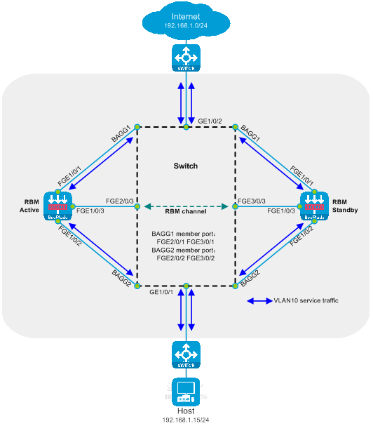
Side-mounted primary and secondary deployment of Layer 2 diversion
Side-mounted primary and secondary deployment of Layer 2 diversion is a type of Layer 2 SecBlade module deployment method, in which the switch uses QoS policy for stream diversion, the SecBlade module operates in transparency mode, and the backup mode for the SecBlade module is the primary and secondary mode. This deployment method is generally used in scenarios where the upstream and downstream are in the same network segment and VLAN, and there is a desire to maintain the existing network structure unchanged.
As shown in the diagram below, two SecBlade modules are installed in slots 2 and 3 of the switch. They need to perform security checks on the traffic of VLAN10. VLAN10 is in the same network segment.
Figure 14 Attached Primary and Secondary Deployment Two-Layer Diversion Logic Diagram
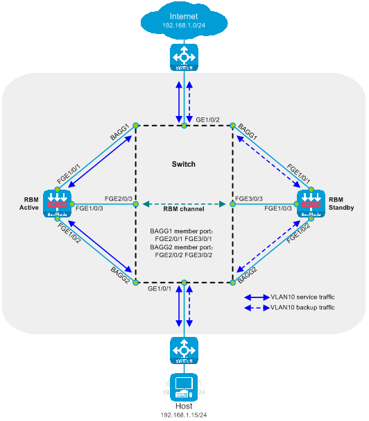
The working mode of side-mounted primary and secondary deployment two-layer diversion:
· On the switch, both upstream and downstream interfaces are partitioned in the same VLAN, and traffic is redirected to the SecBlade module through the QoS policy.
· The switch processes service by configuring the maximum selected port number and port privilege level preference in the aggregation group for the primary SecBlade module.
· The SecBlade module interface operates at the Layer 2, and messages are forwarded by looking up the MAC address table.
· The card insertion of SecBlade achieves the primary-secondary backup through the linkage state of the RBM interface.
· Upon receiving the return traffic from the SecBlade module, the switch redirects the traffic to upstream and downstream devices via QoS policy.
Advantages and disadvantages of the side-hanging primary and secondary deployment and Layer 2 diversion:
· Advantages: No need to change the existing network topology during deployment, faster deployment of SecBlade module, traffic for services requiring security functions can be diverted, while other traffic continues to follow the original path.
· Drawbacks: The diversion strategy is complex, leading to increased maintenance difficulty. It does not support routing functions and only supports a limited range of security functions.
Transparent main and standby deployment in a direct path
The transparent direct route primary and backup deployment is a method of deploying Layer 2 SecBlade module, where the switch utilizes VLAN diversion. The working mode of the SecBlade module is set to the Bridge mode across VLANs, with a backup mode set to the primary and backup mode. This type of deployment is typically used in scenarios where upstream and downstream belong to the same network segment but different VLANs.
As shown in the illustration below, two SecBlade modules are installed in slot 2 and 3 of the switch, needed for security inspection of the traffic between the Host and the Internet. Both networks are in the same network segment.
Figure 15 Transparency Direct Route Primary and Backup Deployment Logic Diagram
Working method of deployment for primary and secondary transparency direct route:
· The upstream and downstream interfaces on the switch operate at Layer 2 and are divided into different VLANs. By allocating the diversion port and the service port to the same VLAN, Layer 2 intercommunication within the same VLAN is realized, thereby introducing upstream and downstream traffic into the SecBlade module.
· The switch manages operations by configuring the maximum selected port number and port privilege level within the aggregation group, prioritizing the primary SecBlade module.
· The SecBlade module interface operates at Layer 2, forwarding packets by checking the MAC address table, and performs VLAN translation on both incoming and outgoing packets using the cross-VLAN mode Bridge.
· The SecBlade module achieves primary-secondary backup through the RBM linked interface status.
· After the switch receives the traffic return from the SecBlade module insertion, it performs layer 2 forwarding to upstream and downstream devices.
Pros and cons of transparency-based primary and backup deployment:
· Advantages: The setup logic is simple, eliminating the need for complex QoS policy traffic diversion configurations. Fault processing is straightforward, and it only diverts the service requiring security processing while other traffic continues to be forwarded along the original path.
· Drawbacks: Does not support routing functions, only supports a limited number of security functions, the existing network topology needs to be altered during deployment, two VLANs are required to deploy a single service, and the supported number of services is reduced by half.
SecBlade module dual-master deployment overview
Side-mounted dual-master deployment, directing traffic at Layer 3
Side-mounted dual-master deployment with Layer 3 traffic diversion is a Layer 3 deployment method for the SecBlade module. In this deployment, the router uses policy routing to divert traffic, the SecBlade module operates in routing mode, and the SecBlade module backup operates in dual-master mode. This deployment is typically used in scenarios where the upstream and downstream are in different network segments and there is no desire to change the original network configuration.
As shown in the diagram, two SecBlade modules are installed in slots 2 and 3 of the router, and security checks need to be done on the traffic between the Host and the Internet. The two networks are in different network segments, with the router serving as their gateway.
Figure 16 Side-mounted diagram with dual-master three-stratum flow logic

Working method of side-mounted dual-master deployment with Layer 3 diversion:
· The upstream and downstream interfaces on the router are divided into different network segments. By configuring policy routing, the next hop of the upstream and downstream traffic is directed to the SecBlade module.
· The router achieves load sharing through policy routing, equal-weight multi-hop next hop, and dual VRRP.
· The SecBlade module interface operates at Layer 3, and packets are forwarded by looking up the routing table.
· The SecBlade module accomplishes mutual backup through the linkage of RBM and VRRP.
· Upon receiving the traffic backflow from the SecBlade module, the router forwards it to the upstream and downstream devices at Layer 3.
Advantages and disadvantages of side-mounted dual-master deployment with Layer 3 traffic diversion:
· Advantages: During deployment, there is no need to change the existing network topology, which allows for faster deployment of SecBlade modules. It is possible to divert only the traffic requiring security functions, while other traffic continues to be forwarded along the original path. This supports a wide range of routing and security functions, such as OSPF, NAT, LB, SecPolicy, and DPI.
· Disadvantages: The drainage policy is complex, which increases the difficulty of maintenance, and it cannot be used concurrently with the fast forwarding load sharing function.
Dual-primary deployment of Layer 3 direct route (dividing VRF)
The Layer 3 direct routing dual-master deployment (VRF partitioning) is a method of deploying SecBlade module in a Layer 3 manner. In this deployment, routers isolate the Layer 3 traffic diversion after VRF partitioning. The SecBlade module operates in routing mode, and its backup mode is dual-master mode. This deployment method is typically suitable for scenarios where the upstream and downstream network segments differ and the original network structure can be altered.
As shown in the diagram below, two SecBlade modules are installed in slots 2 and 3 of the router, which need to perform security checks on the traffic between the Host and the Internet. These two networks are in different network segments, and the router serves as their gateway.
Figure 17 Logical diagram of Layer 3 straight dual-master deployment (dividing VRF)
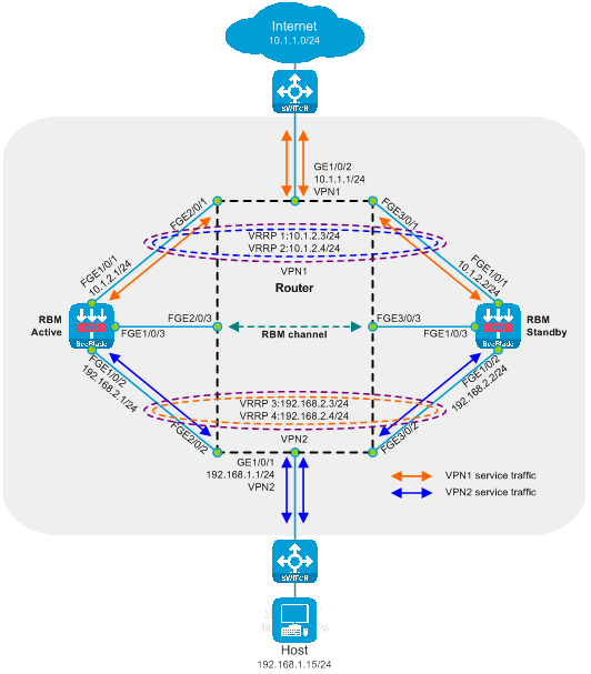
The working mechanism of Layer 3 straight path dual-main deployment (with VRF segmentation):
· On the router, the upstream and downstream interfaces operate at stratum three and are partitioned into different VRFs. The drain port and service port are categorized into the same VRF. The upstream and downstream traffic is directed into the SecBlade module through a static route.
· The router achieves load sharing through equivalent static routes and dual VRRP.
· The SecBlade module interface operates at Layer 3, forwarding packets by looking up the routing table.
· The SecBlade module achieves mutual backup through RBM linkage with VRRP.
· After receiving the traffic loopback from the SecBlade module, the router forwards it to the upstream and downstream devices on Layer 3.
The pros and cons of deploying a Layer 3 direct network with dual masters (defining VRF):
· Advantages: It supports a wide range of routing and security functions, such as OSPF, NAT, LB, SecPolicy, and DPI, etc., without the need for configuration and maintenance of complex policy routing.
· Disadvantage: It requires additional planning of network addresses, and changes to the existing network topology are needed during deployment.
Dual-master deployment of Layer 3 direct route (VLAN partitioning)
The Layer 3 direct route dual-master deployment (VLAN partitioning) is a Layer 3 deployment method for the SecBlade module. In this deployment method, switches employ two-layer diversion after VLAN partitioning, and the SecBlade module operates in route mode with a backup mode set to dual-master mode. This deployment is typically used in scenarios with different network segments and VLANs upstream and downstream.
As shown in the diagram below, two SecBlade modules are installed in slots 2 and 3 of the switch, and it's required to perform security checks on the traffic between the Host and the Internet. The two networks are in different network segments, and their gateways are served by upstream and downstream routers.
Figure 18 Logical diagram of a Layer 3 direct path dual-main deployment (dividing VLAN)
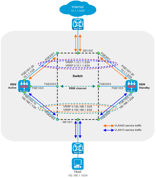
Working method of a three-stratum direct route dual-master deployment (dividing VLAN):
· The upstream and downstream interfaces of the switch operate at Layer 2 and are divided into different VLANs. The diversion port and service ports are assigned to the same VLAN. This allows the second-layer intercommunication within the same VLAN, enabling the upstream and downstream traffic to be directed to the SecBlade module.
· The uplink and downlink devices achieve load sharing with dual VRRP through equivalent static routing.
· The SecBlade module works at stratum three, where packets are forwarded after checking the routing table.
· The SecBlade module achieves mutual backup by interconnecting RBM and VRRP.
· After receiving the return traffic from the SecBlade module insertion, the switch forwards it to the upstream and downstream devices at Layer 2.
The Pros and Cons of Dual Main Deployment in Layer 3 Straight Road (Divided VLAN):
· Advantages: Supports a variety of routing and security features, such as OSPF, NAT, LB, SecPolicy, and DPI, without the need for configuration and maintenance of complex policy routing.
· Drawback: Requires additional planning of network addresses and changes to the existing network topology during deployment.
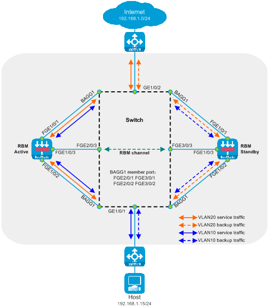
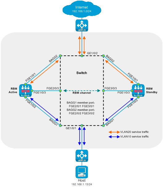
Deploy a side-mounted dual-master setup with Layer 2 stream diversion
The side-mounted dual-master deployment of Layer 2 diversion is a type of Layer 2 SecBlade module deployment method. In this deployment style, the switch utilizes QoS policy for diversion. The working mode of the SecBlade module is in transparent mode, and the backup mode of the SecBlade module is in dual-master mode. Generally, this deployment method is used in scenarios where upstream and downstream are in the same network segment and VLAN and there is no desire to change the existing network setup.
As shown in the following figure, two SecBlade modules are installed in slots 2 and 3 of the switch, and security detection is required for traffic in VLAN10. VLAN10 is in the same network segment.
Figure 19 Attached Dual-Master Deployment with Secondary Layer Stream Diversion Logic Diagram
The working method of deploying the secondary stream in the dual-master, side-mounted configuration.
· The switch's upstream and downstream interfaces are divided into the same VLAN, redirecting traffic to the SecBlade module through the QoS policy.
· The switch achieves load sharing by implementing interface aggregation.
· The SecBlade module interface operates at the Layer 2, forwarding packets by looking up the MAC address table.
· The SecBlade module achieves mutual backup through the RBM linkage interface status.
· Upon receiving the return traffic from the SecBlade module, the switch redirects the traffic to the upstream and downstream devices through the QoS policy.
The pros and cons of deploying a two-tier diversion in a side-mounted dual-master setup:
· Advantage: No need to alter the existing network topology during deployment, allowing for faster SecBlade module implementation. It also enables the diversion of only those servicees needing security function processing, while other traffic continues to be forwarded along the original path.
· Drawbacks: The drainage policy is complex, making maintenance more difficult. It lacks routing function and only supports limited security features.
Transparent dual-master deployment with direct path
Transparent direct dual-main deployment is a two-stratum SecBlade module deployment method. In this deployment method, the switch uses VLAN partitioning to divert traffic, the SecBlade module operates in cross-VLAN mode (Bridge), and the SecBlade module backup mode is dual-main mode. This deployment method is generally used in scenarios with the same network segment but different VLANs between upstream and downstream.
As shown in the diagram below, two SecBlade modules are installed in slot 2 and 3 of the switch and security checks need to be performed on the traffic between the Host and the Internet. Both networks are in the same network segment.
Figure 20 Transparency Direct Path Dual-Master Deployment Logic Diagram
The switch realizes load sharing through interface aggregation. The SecBlade module achieves mutual backup via RBM linked interface status.
The working mode of transparent straight-path dual-master deployment:
· The upstream and downstream interfaces on the switch work on layer two and are divided into different VLANs. By categorizing the diversion port and service port into the same VLAN, layer two communication within the same VLAN is achieved, thus allowing upstream and downstream traffic to be directed to the SecBlade module.
· The switch accomplishes load sharing through interface aggregation.
· The SecBlade module interface operates at Layer 2, forwarding packets by checking the MAC address table. It also translates the VLAN of uplink and downlink packets through a cross-VLAN mode Bridge.
· The SecBlade module achieves mutual backup through the RBM linkage interface state.
· Upon receiving the return traffic from the SecBlade module insertion, the switch forwards it to the upstream and downstream devices via the Layer 2.
Advantages and disadvantages of transparent straight-line dual-master deployment:
· Advantages: The configuration logic is simple, without the need for complex QoS policy-based traffic diversion configurations, fault handling is simple, and only traffic requiring security processing can be diverted, while other traffic continues to be forwarded along the original path.
· Drawbacks: It doesn't support routing functions and only supports a limited number of security features. Changes to the existing network topology are required during deployment. Two VLANs are needed for one service deployment, thereby halving the number of services supported.
Example of standalone deployment configuration for SecBlade module
Side-mounted deployment of SecBlade module for Layer 3 traffic diversion
Network configuration
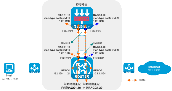
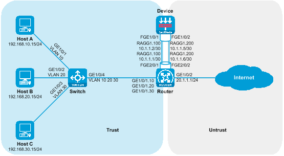
Host A, Host B, and Host C communicate with the Internet through access to the switch. For security reasons, a SecBlade module device needs to be deployed on the router for protection, and the application requirements are as follows:
· Switch assigns Host A, Host B, and Host C to VLAN 10, VLAN 20, and VLAN 30 respectively, allowing traffic between the hosts and the Internet to pass through.
· The router interfaces with the host, internet, and device at three levels, redirecting the upstream and downstream traffic to the device via policy routing. The traffic returned from the device is forwarded by looking up the routing table.
· The device interfaces with the router at Layer 3, checking the static routing table to forward traffic between the host and the internet.
Figure 21 Side-mounted deployment network diagram of SecBlade module using stratum three for stream diversion.
|
Device |
Interface |
IP address |
Device |
Interface |
IP address |
|
Host A |
N/A |
192.168.10.15/24 |
Device |
RAGG1.100 |
10.1.1.2/30 |
|
Host B |
N/A |
192.168.20.15/24 |
|
RAGG1.200 |
10.1.1.5/30 |
|
Host C |
N/A |
192.168.30.15/24 |
|
|
|
|
Router |
GE1/0/1.10 |
192.168.10.1/24 |
|
|
|
|
|
GE1/0/1.20 |
192.168.20.1/24 |
|
|
|
|
|
GE1/0/1.30 |
192.168.30.1/24 |
|
|
|
|
|
RAGG1.100 |
10.1.1.1/30 |
|
|
|
|
|
RAGG1.200 |
10.1.1.6/30 |
|
|
|
|
|
GE1/0/2 |
20.1.1.1/24 |
|
|
|
Procedures
Configure the Switch.
Create VLAN 10, VLAN 20, and VLAN 30. Add GigabitEthernet1/0/1, GigabitEthernet1/0/2, and GigabitEthernet1/0/3 to VLAN 10, VLAN 20, and VLAN 30, respectively.
<Switch> system-view
[Switch] vlan 10
[Switch-vlan10] port gigabitethernet 1/0/1
[Switch-vlan10] quit
[Switch] vlan 20
[Switch-vlan20] port gigabitethernet 1/0/2
[Switch-vlan20] quit
[Switch] vlan 30
[Switch-vlan30] port gigabitethernet 1/0/3
[Switch-vlan30] quit
Configure the link type of GigabitEthernet1/0/4 as Trunk, and allow packets of VLAN 10, VLAN 20, and VLAN 30 to pass.
[Switch] interface gigabitethernet 1/0/4
[Switch-GigabitEthernet1/0/4] port link-type trunk
[Switch-GigabitEthernet1/0/4] port trunk permit vlan 10 20 30
[Switch-GigabitEthernet1/0/4] quit
Configure Router.
Configure the IP for the GigabitEthernet1/0/2 interface.
<Router> system-view
[Router] interface gigabitethernet 1/0/2
[Router-GigabitEthernet1/0/2] ip address 20.1.1.1 24
[Router-GigabitEthernet1/0/2] quit
Create a Layer 3 aggregation interface 1.
[Router] interface route-aggregation 1
[Router-Route-Aggregation1] quit
Create Layer 3 aggregation subinterfaces Route-Aggregation1.100 and Route-Aggregation1.200, activate the Dot1q termination function, respectively terminate VLAN 100 and VLAN 200, and configure the interface IP.
[Router] interface route-aggregation 1.100
[Router-Route-Aggregation1.100] vlan-type dot1q vid 100
[Router-Route-Aggregation1.100] ip address 10.1.1.1 30
[Router-Route-Aggregation1.100] quit
[Router] interface route-aggregation 1.200
[Router-Route-Aggregation1.200] vlan-type dot1q vid 200
[Router-Route-Aggregation1.200] ip address 10.1.1.6 30
[Router-Route-Aggregation1.200] quit
Add FortyGigE2/0/1 and FortyGigE2/0/2 to aggregation group 1.
[Router] interface range fortygige 2/0/1 fortygige 2/0/2
[Router-if-range] port link-aggregation group 1
[Router-if-range] quit
Create Layer 3 subinterfaces GigabitEthernet1/0/1.10, GigabitEthernet1/0/1.20, and GigabitEthernet1/0/1.30, enable Dot1q termination function, respectively terminate VLAN 10, VLAN 20 and VLAN 30, and configure interface IP.
[Router] interface gigabitethernet 1/0/1.10
[Router-GigabitEthernet1/0/1.10] vlan-type dot1q vid 10
[Router-GigabitEthernet1/0/1.10] ip address 192.168.10.1 24
[Router-GigabitEthernet1/0/1.10] quit
[Router] interface gigabitethernet 1/0/1.20
[Router-GigabitEthernet1/0/1.20] vlan-type dot1q vid 20
[Router-GigabitEthernet1/0/1.20] ip address 192.168.20.1 24
[Router-GigabitEthernet1/0/1.20] quit
[Router] interface gigabitethernet 1/0/1.30
[Router-GigabitEthernet1/0/1.30] vlan-type dot1q vid 30
[Router-GigabitEthernet1/0/1.30] ip address 192.168.30.1 24
[Router-GigabitEthernet1/0/1.30] quit
Turn off the fast load-sharing function to prevent Layer 3 loops.
[Router] undo ip fast-forwarding load-sharing
Create an advanced IPv4 ACL to match both upstream and downstream traffic.
[Router] acl advanced 3001
[Router-acl-ipv4-adv-3001] rule permit ip source 192.168.10.0 0.0.0.255 destination 20.1.1.0 0.0.0.255
[Router-acl-ipv4-adv-3001] quit
[Router] acl advanced 3002
[Router-acl-ipv4-adv-3002] rule permit ip source 192.168.20.0 0.0.0.255 destination 20.1.1.0 0.0.0.255
[Router-acl-ipv4-adv-3002] quit
[Router] acl advanced 3003
[Router-acl-ipv4-adv-3003] rule permit ip source 192.168.30.0 0.0.0.255 destination 20.1.1.0 0.0.0.255
[Router-acl-ipv4-adv-3003] quit
[Router] acl advanced 3004
[Router-acl-ipv4-adv-3004] rule permit ip source 20.1.1.0 0.0.0.255 destination 192.168.10.0 0.0.0.255
[Router-acl-ipv4-adv-3004] rule permit ip source 20.1.1.0 0.0.0.255 destination 192.168.20.0 0.0.0.255
[Router-acl-ipv4-adv-3004] rule permit ip source 20.1.1.0 0.0.0.255 destination 192.168.30.0 0.0.0.255
[Router-acl-ipv4-adv-3004] quit
Configure the policy routing and bind the policy routing to the interface.
[Router] policy-based-route vlan10out permit node 10
[Router-pbr-vlan10out-10] if-match acl 3001
[Router-pbr-vlan10out-10] apply next-hop 10.1.1.2
[Router-pbr-vlan10out-10] quit
[Router] policy-based-route vlan20out permit node 10
[Router-pbr-vlan20out-10] if-match acl 3002
[Router-pbr-vlan20out-10] apply next-hop 10.1.1.2
[Router-pbr-vlan20out-10] quit
[Router] policy-based-route vlan30out permit node 10
[Router-pbr-vlan30out-10] if-match acl 3003
[Router-pbr-vlan30out-10] apply next-hop 10.1.1.2
[Router-pbr-vlan30out-10] quit
[Router] policy-based-route internetin permit node 10
[Router-pbr-internetin-10] if-match acl 3004
[Router-pbr-internetin-10] apply next-hop 10.1.1.5
[Router-pbr-internetin-10] quit
[Router] interface gigabitethernet 1/0/1.10
[Router-GigabitEthernet1/0/1.10] ip policy-based-route vlan10out
[Router-GigabitEthernet1/0/1.10] quit
[Router] interface gigabitethernet 1/0/1.20
[Router-GigabitEthernet1/0/1.20] ip policy-based-route vlan20out
[Router-GigabitEthernet1/0/1.20] quit
[Router] interface gigabitethernet 1/0/1.30
[Router-GigabitEthernet1/0/1.30] ip policy-based-route vlan30out
[Router-GigabitEthernet1/0/1.30] quit
[Router] interface gigabitethernet 1/0/2
[Router-GigabitEthernet1/0/2] ip policy-based-route internetin
[Router-GigabitEthernet1/0/2] quit
Configure Device
Create Layer 3 aggregate interface 1.
<Device> system-view
[Device] interface route-aggregation 1
[Device-Route-Aggregation1] quit
Create Layer 3 aggregation sub-interfaces Route-Aggregation1.100 and Route-Aggregation1.200, enable the Dot1q termination function, and respectively terminate VLAN 100 and VLAN 200. Then, configure the interface IP.
[Device] interface route-aggregation 1.100
[Device-Route-Aggregation1.100] vlan-type dot1q vid 100
[Device-Route-Aggregation1.100] ip address 10.1.1.2 30
[Device-Route-Aggregation1.100] quit
[Device] interface route-aggregation 1.200
[Device-Route-Aggregation1.200] vlan-type dot1q vid 200
[Device-Route-Aggregation1.200] ip address 10.1.1.5 30
[Device-Route-Aggregation1.200] quit
Add FortyGigE1/0/1 and FortyGigE1/0/2 to the aggregation group 1.
[Device] interface range fortygige 1/0/1 fortygige 1/0/2
[Device-if-range] port link-aggregation group 1
[Device-if-range] quit
Add Route-Aggregation1.100 and Route-Aggregation1.200 to the 'Trust' and 'Untrust' security domains respectively.
[Device] security-zone name trust
[Device-security-zone-Trust] import interface route-aggregation 1.100
[Device-security-zone-Trust] quit
[Device] security-zone name untrust
[Device-security-zone-Untrust] import interface route-aggregation 1.200
[Device-security-zone-Untrust] quit
Configure the security policy to allow inter-domain messages to pass.
[Device] security-policy ip
[Device-security-policy-ip] rule name trust-untrust
[Device-security-policy-ip-0-trust-untrust] action pass
[Device-security-policy-ip-0-trust-untrust] source-zone trust
[Device-security-policy-ip-0-trust-untrust] destination-zone untrust
[Device-security-policy-ip-0-trust-untrust] quit
[Device-security-policy-ip] rule name untrust-trust
[Device-security-policy-ip-1-untrust-trust] action pass
[Device-security-policy-ip-1-untrust-trust] source-zone untrust
[Device-security-policy-ip-1-untrust-trust] destination-zone trust
[Device-security-policy-ip-1-untrust-trust] quit
[Device-security-policy-ip] quit
Configure the static route to guide the traffic forwarding in both upstream and downstream directions.
[Device] ip route-static 192.168.10.0 24 10.1.1.1
[Device] ip route-static 192.168.20.0 24 10.1.1.1
[Device] ip route-static 192.168.30.0 24 10.1.1.1
[Device] ip route-static 20.1.1.0 24 10.1.1.6
Verifying the configuration
Host A conducts a connectivity ping test to the Internet. The Internet address 20.1.1.1 can be successfully pinged.
C:\>ping 20.1.1.1
Pinging 20.1.1.1 with 32 bytes of data:
Reply from 20.1.1.1: bytes=32 time=3ms TTL=254
Reply from 20.1.1.1: bytes=32 time=2ms TTL=254
Reply from 20.1.1.1: bytes=32 time=1ms TTL=254
Reply from 20.1.1.1: bytes=32 time=2ms TTL=254
Ping statistics for 20.1.1.1:
Packets: Sent = 4, Received = 4, Lost = 0 (0% loss),
Approximate round trip times in milli-seconds:
Minimum = 1ms, Maximum = 3ms, Average = 2ms
On Host B, test the connectivity to the Internet using the 'ping' command, and it successfully pings the Internet address 20.1.1.1.
C:\>ping 20.1.1.1
Pinging 20.1.1.1 with 32 bytes of data:
Reply from 20.1.1.1: bytes=32 time=3ms TTL=254
Reply from 20.1.1.1: bytes=32 time=2ms TTL=254
Reply from 20.1.1.1: bytes=32 time=1ms TTL=254
Reply from 20.1.1.1: bytes=32 time=2ms TTL=254
Ping statistics for 20.1.1.1:
Packets: Sent = 4, Received = 4, Lost = 0 (0% loss),
Approximate round trip times in milli-seconds:
Minimum = 1ms, Maximum = 3ms, Average = 2ms
Host C conducts a ping test to check the connectivity to the Internet and can successfully ping the Internet address 20.1.1.1.
C:\>ping 20.1.1.1
Pinging 20.1.1.1 with 32 bytes of data:
Reply from 20.1.1.1: bytes=32 time=3ms TTL=254
Reply from 20.1.1.1: bytes=32 time=2ms TTL=254
Reply from 20.1.1.1: bytes=32 time=1ms TTL=254
Reply from 20.1.1.1: bytes=32 time=2ms TTL=254
Ping statistics for 20.1.1.1:
Packets: Sent = 4, Received = 4, Lost = 0 (0% loss),
Approximate round trip times in milli-seconds:
Minimum = 1ms, Maximum = 3ms, Average = 2ms
Check the session table on the Device, there is a session table between the Host and 20.1.1.1.
[Device] display session table ipv4
Slot 1:
Initiator:
Source IP/port: 192.168.10.15/12005
Destination IP/port: 20.1.1.1/2048
DS-Lite tunnel peer: -
VPN instance/VLAN ID/Inline ID: -/-/-
Protocol: ICMP(1)
Inbound interface: Route-Aggregation1.100
Source security zone: Trust
Initiator:
Source IP/port: 192.168.20.15/12005
Destination IP/port: 20.1.1.1/2048
DS-Lite tunnel peer: -
VPN instance/VLAN ID/Inline ID: -/-/-
Protocol: ICMP(1)
Inbound interface: Route-Aggregation1.100
Source security zone: Trust
Initiator:
Source IP/port: 192.168.30.15/12005
Destination IP/port: 20.1.1.1/2048
DS-Lite tunnel peer: -
VPN instance/VLAN ID/Inline ID: -/-/-
Protocol: ICMP(1)
Inbound interface: Route-Aggregation1.100
Source security zone: Trust
Configuration file
Switch
#
vlan 10
#
vlan 20
#
vlan 30
#
interface GigabitEthernet1/0/1
port access vlan 10
#
interface GigabitEthernet1/0/2
port access vlan 20
#
interface GigabitEthernet1/0/3
port access vlan 30
#
interface GigabitEthernet1/0/4
port link-type trunk
port trunk permit vlan 10 20 30
#
Router
#
undo ip fast-forwarding load-sharing
#
policy-based-route internetin permit node 10
if-match acl 3004
apply next-hop 10.1.1.5
#
policy-based-route vlan10out permit node 10
if-match acl 3001
apply next-hop 10.1.1.2
#
policy-based-route vlan20out permit node 10
if-match acl 3002
apply next-hop 10.1.1.2
#
policy-based-route vlan30out permit node 10
if-match acl 3003
apply next-hop 10.1.1.2
#
interface Route-Aggregation1
#
interface Route-Aggregation1.100
ip address 10.1.1.1 255.255.255.252
vlan-type dot1q vid 100
#
interface Route-Aggregation1.200
ip address 10.1.1.6 255.255.255.252
vlan-type dot1q vid 200
#
interface GigabitEthernet1/0/1.10
ip address 192.168.10.1 255.255.255.0
vlan-type dot1q vid 10
ip policy-based-route vlan10out
#
interface GigabitEthernet1/0/1.20
ip address 192.168.20.1 255.255.255.0
vlan-type dot1q vid 20
ip policy-based-route vlan20out
#
interface GigabitEthernet1/0/1.30
ip address 192.168.30.1 255.255.255.0
vlan-type dot1q vid 30
ip policy-based-route vlan30out
#
interface GigabitEthernet1/0/2
ip address 20.1.1.1 255.255.255.0
ip policy-based-route internetin
#
interface FortyGigE2/0/1
port link-aggregation group 1
#
interface FortyGigE2/0/2
port link-aggregation group 1
#
acl advanced 3001
rule 0 permit ip source 192.168.10.0 0.0.0.255 destination 20.1.1.0 0.0.0.255
#
acl advanced 3002
rule 0 permit ip source 192.168.20.0 0.0.0.255 destination 20.1.1.0 0.0.0.255
#
acl advanced 3003
rule 0 permit ip source 192.168.30.0 0.0.0.255 destination 20.1.1.0 0.0.0.255
#
acl advanced 3004
rule 0 permit ip source 20.1.1.0 0.0.0.255 destination 192.168.10.0 0.0.0.255
rule 5 permit ip source 20.1.1.0 0.0.0.255 destination 192.168.20.0 0.0.0.255
rule 10 permit ip source 20.1.1.0 0.0.0.255 destination 192.168.30.0 0.0.0.255
#
Device
#
interface Route-Aggregation1
#
interface Route-Aggregation1.100
ip address 10.1.1.2 255.255.255.252
vlan-type dot1q vid 100
#
interface Route-Aggregation1.200
ip address 10.1.1.5 255.255.255.252
vlan-type dot1q vid 200
#
interface FortyGigE1/0/1
port link-aggregation group 1
#
interface FortyGigE1/0/2
port link-aggregation group 1
#
security-zone name Trust
import interface Route-Aggregation1.100
#
security-zone name Untrust
import interface Route-Aggregation1.200
#
ip route-static 20.1.1.0 24 10.1.1.6
ip route-static 192.168.10.0 24 10.1.1.1
ip route-static 192.168.20.0 24 10.1.1.1
ip route-static 192.168.30.0 24 10.1.1.1
#
security-policy ip
rule 0 name trust-untrust
action pass
source-zone trust
destination-zone untrust
rule 1 name untrust-trust
action pass
source-zone untrust
destination-zone trust
#
Deploy SecBlade module (partition VRF) in a Layer 3 direct path deployment.
Network configuration
Host A, Host B, and Host C communicate with the Internet through access to the Switch switch and Router router. For security reasons, a SecBlade module Device needs to be deployed on the Router router for security protection, with application requirements as follows:
· Switch assigns Host A, Host B, and Host C to VLAN 10, VLAN 20, and VLAN 30, respectively, and transparently passes traffic between the hosts and the Internet.
· The router interfaces with the host, the internet and the device on three levels. The downstream port and Route-Aggregation1.100 are assigned to the VPN host, while the upstream port and Route-Aggregation1.200 are allocated to the VPN internet. The static route table is consulted to forward traffic between the host and the internet.
· The device interfaces with the Router at Layer 3, checking the static route table to forward traffic between the Host and the Internet.
Figure 22 Layer 3 linear deployment of SecBlade module (dividing VRF) network diagram
|
Device |
Interface |
IP address |
Device |
Interface |
IP address |
|
Host A |
N/A |
192.168.10.15/24 |
Device |
RAGG1.100 |
10.1.1.2/30 |
|
Host B |
N/A |
192.168.20.15/24 |
|
RAGG1.200 |
10.1.1.5/30 |
|
Host C |
N/A |
192.168.30.15/24 |
|
|
|
|
Router |
GE1/0/1.10 |
192.168.10.1/24 |
|
|
|
|
|
GE1/0/1.20 |
192.168.20.1/24 |
|
|
|
|
|
|
192.168.30.1/24 |
|
|
|
|
|
RAGG1.100 |
10.1.1.1/30 |
|
|
|
|
|
RAGG1.200 |
10.1.1.6/30 |
|
|
|
Procedures
Configure the Switch
Create VLAN 10, VLAN 20, and VLAN 30. Add GigabitEthernet1/0/1, GigabitEthernet1/0/2, and GigabitEthernet1/0/3 to VLAN 10, VLAN 20, and VLAN 30 respectively.
<Switch> system-view
[Switch] vlan 10
[Switch-vlan10] port gigabitethernet 1/0/1
[Switch-vlan10] quit
[Switch] vlan 20
[Switch-vlan20] port gigabitethernet 1/0/2
[Switch-vlan20] quit
[Switch] vlan 30
[Switch-vlan30] port gigabitethernet 1/0/3
[Switch-vlan30] quit
Configure the link type of GigabitEthernet1/0/4 as Trunk, and allow packets from VLAN 10, VLAN 20, and VLAN 30 to pass.
[Switch] interface gigabitethernet 1/0/4
[Switch-GigabitEthernet1/0/4] port link-type trunk
[Switch-GigabitEthernet1/0/4] port trunk permit vlan 10 20 30
[Switch-GigabitEthernet1/0/4] quit
Configure the Router
Create a VPN-instance for host and internet.
[Router] ip vpn-instance host
[Router-vpn-instance-host] quit
[Router] ip vpn-instance internet
[Router-vpn-instance-internet] quit
Create a Layer 3 aggregation interface 1.
[Router] interface route-aggregation 1
[Router-Route-Aggregation1] quit
Create Layer 3 aggregation subinterfaces Route-Aggregation1.100 and Route-Aggregation1.200, enable Dot1q termination function, terminate VLAN 100 and VLAN 200 respectively, bind the VPN instance and configure the interface IP.
[Router] interface route-aggregation 1.100
[Router-Route-Aggregation1.100] vlan-type dot1q vid 100
[Router-Route-Aggregation1.100] ip binding vpn-instance host
[Router-Route-Aggregation1.100] ip address 10.1.1.1 30
[Router-Route-Aggregation1.100] quit
[Router] interface route-aggregation 1.200
[Router-Route-Aggregation1.200] vlan-type dot1q vid 200
[Router-Route-Aggregation1.200] ip binding vpn-instance internet
[Router-Route-Aggregation1.200] ip address 10.1.1.6 30
[Router-Route-Aggregation1.200] quit
Add FortyGigE2/0/1 and FortyGigE2/0/2 to aggregation group 1.
[Router] interface range fortygige 2/0/1 fortygige 2/0/2
[Router-if-range] port link-aggregation group 1
[Router-if-range] quit
Create Layer 3 subinterfaces GigabitEthernet1/0/1.10, GigabitEthernet1/0/1.20, and GigabitEthernet1/0/1.30, enable Dot1q termination function, respectively terminate VLAN 10, VLAN 20, and VLAN 30, bind VPN-instance and configure interface IPs.
[Router] interface gigabitethernet 1/0/1.10
[Router-GigabitEthernet1/0/1.10] vlan-type dot1q vid 10
[Router-GigabitEthernet1/0/1.10] ip binding vpn-instance host
[Router-GigabitEthernet1/0/1.10] ip address 192.168.10.1 24
[Router-GigabitEthernet1/0/1.10] quit
[Router] interface gigabitethernet 1/0/1.20
[Router-GigabitEthernet1/0/1.20] vlan-type dot1q vid 20
[Router-GigabitEthernet1/0/1.20] ip binding vpn-instance host
[Router-GigabitEthernet1/0/1.20] ip address 192.168.20.1 24
[Router-GigabitEthernet1/0/1.20] quit
[Router] interface gigabitethernet 1/0/1.30
[Router-GigabitEthernet1/0/1.30] vlan-type dot1q vid 30
[Router-GigabitEthernet1/0/1.30] ip binding vpn-instance host
[Router-GigabitEthernet1/0/1.30] ip address 192.168.30.1 24
[Router-GigabitEthernet1/0/1.30] quit
Configure the IP of the GigabitEthernet1/0/2 interface and bind it to the VPN instance.
[Router] interface gigabitethernet 1/0/2
[Router-GigabitEthernet1/0/2] ip binding vpn-instance internet
[Router-GigabitEthernet1/0/2] ip address 20.1.1.1 24
[Router-GigabitEthernet1/0/2] quit
Configure static route to guide traffic forwarding for both upstream and downstream flows.
[Router] ip route-static vpn-instance host 20.1.1.0 24 vpn-instance host 10.1.1.2
[Router] ip route-static vpn-instance internet 192.168.10.0 24 vpn-instance internet 10.1.1.5
[Router] ip route-static vpn-instance internet 192.168.20.0 24 vpn-instance internet 10.1.1.5
[Router] ip route-static vpn-instance internet 192.168.30.0 24 vpn-instance internet 10.1.1.5
Configure Device
Create a three-stratum aggregation interface 1.
<Device> system-view
[Device] interface route-aggregation 1
[Device-Route-Aggregation1] quit
Create the Layer 3 aggregation subinterfaces Route-Aggregation1.100 and Route-Aggregation1.200, activate the Dot1q termination function, respectively terminate VLAN 100 and VLAN 200, and configure the interface IP.
[Device] interface route-aggregation 1.100
[Device-Route-Aggregation1.100] vlan-type dot1q vid 100
[Device-Route-Aggregation1.100] ip address 10.1.1.2 30
[Device-Route-Aggregation1.100] quit
[Device] interface route-aggregation 1.200
[Device-Route-Aggregation1.200] vlan-type dot1q vid 200
[Device-Route-Aggregation1.200] ip address 10.1.1.5 30
[Device-Route-Aggregation1.200] quit
Add FortyGigE1/0/1 and FortyGigE1/0/2 to aggregation group 1.
[Device] interface range fortygige 1/0/1 fortygige 1/0/2
[Device-if-range] port link-aggregation group 1
[Device-if-range] quit
Add Route-Aggregation1.100 and Route-Aggregation1.200 to the security domains Trust and Untrust, respectively.
[Device] security-zone name trust
[Device-security-zone-Trust] import interface route-aggregation 1.100
[Device-security-zone-Trust] quit
[Device] security-zone name untrust
[Device-security-zone-Untrust] import interface route-aggregation 1.200
[Device-security-zone-Untrust] quit
Configure the security policy to allow inter-domain messages to pass.
[Device] security-policy ip
[Device-security-policy-ip] rule name trust-untrust
[Device-security-policy-ip-0-trust-untrust] action pass
[Device-security-policy-ip-0-trust-untrust] source-zone trust
[Device-security-policy-ip-0-trust-untrust] destination-zone untrust
[Device-security-policy-ip-0-trust-untrust] quit
[Device-security-policy-ip] rule name untrust-trust
[Device-security-policy-ip-1-untrust-trust] action pass
[Device-security-policy-ip-1-untrust-trust] source-zone untrust
[Device-security-policy-ip-1-untrust-trust] destination-zone trust
[Device-security-policy-ip-1-untrust-trust] quit
[Device-security-policy-ip] quit
Configure static route to guide traffic forwarding for upstream and downstream.
[Device] ip route-static 192.168.10.0 24 10.1.1.1
[Device] ip route-static 192.168.20.0 24 10.1.1.1
[Device] ip route-static 192.168.30.0 24 10.1.1.1
[Device] ip route-static 20.1.1.0 24 10.1.1.6
Verifying the configuration
Host A performs a ping test to check the Internet connectivity and can successfully ping the Internet address 20.1.1.1.
C:\>ping 20.1.1.1
Pinging 20.1.1.1 with 32 bytes of data:
Reply from 20.1.1.1: bytes=32 time=3ms TTL=254
Reply from 20.1.1.1: bytes=32 time=2ms TTL=254
Reply from 20.1.1.1: bytes=32 time=1ms TTL=254
Reply from 20.1.1.1: bytes=32 time=2ms TTL=254
Ping statistics for 20.1.1.1:
Packets: Sent = 4, Received = 4, Lost = 0 (0% loss),
Approximate round trip times in milli-seconds:
Minimum = 1ms, Maximum = 3ms, Average = 2ms
# On Host B, the connectivity to the Internet is tested by pinging, it can ping the Internet address 20.1.1.1 successfully.
C:\>ping 20.1.1.1
Pinging 20.1.1.1 with 32 bytes of data:
Reply from 20.1.1.1: bytes=32 time=3ms TTL=254
Reply from 20.1.1.1: bytes=32 time=2ms TTL=254
Reply from 20.1.1.1: bytes=32 time=1ms TTL=254
Reply from 20.1.1.1: bytes=32 time=2ms TTL=254
Ping statistics for 20.1.1.1:
Packets: Sent = 4, Received = 4, Lost = 0 (0% loss),
Approximate round trip times in milli-seconds:
Minimum = 1ms, Maximum = 3ms, Average = 2ms
Host C performs a ping test to check the connectivity with the Internet and can successfully ping the Internet address 20.1.1.1.
C:\>ping 20.1.1.1
Pinging 20.1.1.1 with 32 bytes of data:
Reply from 20.1.1.1: bytes=32 time=3ms TTL=254
Reply from 20.1.1.1: bytes=32 time=2ms TTL=254
Reply from 20.1.1.1: bytes=32 time=1ms TTL=254
Reply from 20.1.1.1: bytes=32 time=2ms TTL=254
Ping statistics for 20.1.1.1:
Packets: Sent = 4, Received = 4, Lost = 0 (0% loss),
Approximate round trip times in milli-seconds:
Minimum = 1ms, Maximum = 3ms, Average = 2ms
Check the session table on the Device. A session table exists between the Host and 20.1.1.1.
[Device] display session table ipv4
Slot 1:
Initiator:
Source IP/port: 192.168.10.15/12005
Destination IP/port: 20.1.1.1/2048
DS-Lite tunnel peer: -
VPN instance/VLAN ID/Inline ID: -/-/-
Protocol: ICMP(1)
Inbound interface: Route-Aggregation1.100
Source security zone: Trust
Initiator:
Source IP/port: 192.168.20.15/12005
Destination IP/port: 20.1.1.1/2048
DS-Lite tunnel peer: -
VPN instance/VLAN ID/Inline ID: -/-/-
Protocol: ICMP(1)
Inbound interface: Route-Aggregation1.100
Source security zone: Trust
Initiator:
Source IP/port: 192.168.30.15/12005
Destination IP/port: 20.1.1.1/2048
DS-Lite tunnel peer: -
VPN instance/VLAN ID/Inline ID: -/-/-
Protocol: ICMP(1)
Inbound interface: Route-Aggregation1.100
Source security zone: Trust
Configuration file
Switch
#
vlan 10
#
vlan 20
#
vlan 30
#
interface GigabitEthernet1/0/1
port access vlan 10
#
interface GigabitEthernet1/0/2
port access vlan 20
#
interface GigabitEthernet1/0/3
port access vlan 30
#
interface GigabitEthernet1/0/4
port link-type trunk
port trunk permit vlan 10 20 30
#
Router
#
ip vpn-instance host
#
ip vpn-instance internet
#
interface Route-Aggregation1
#
interface Route-Aggregation1.100
ip binding vpn-instance host
ip address 10.1.1.1 255.255.255.252
vlan-type dot1q vid 100
#
interface Route-Aggregation1.200
ip binding vpn-instance internet
ip address 10.1.1.6 255.255.255.252
vlan-type dot1q vid 200
#
interface GigabitEthernet1/0/1.10
ip binding vpn-instance host
ip address 192.168.10.1 255.255.255.0
vlan-type dot1q vid 10
#
interface GigabitEthernet1/0/1.20
ip binding vpn-instance host
ip address 192.168.20.1 255.255.255.0
vlan-type dot1q vid 20
#
interface GigabitEthernet1/0/1.30
ip binding vpn-instance host
ip address 192.168.30.1 255.255.255.0
vlan-type dot1q vid 30
#
interface GigabitEthernet1/0/2
ip binding vpn-instance internet
ip address 20.1.1.1 255.255.255.0
#
interface FortyGigE2/0/1
port link-aggregation group 1
#
interface FortyGigE2/0/2
port link-aggregation group 1
#
ip route-static vpn-instance host 20.1.1.0 24 10.1.1.2
ip route-static vpn-instance internet 192.168.10.0 24 10.1.1.5
ip route-static vpn-instance internet 192.168.20.0 24 10.1.1.5
ip route-static vpn-instance internet 192.168.30.0 24 10.1.1.5
#
Device
#
interface Route-Aggregation1
#
interface Route-Aggregation1.100
ip address 10.1.1.2 255.255.255.252
vlan-type dot1q vid 100
#
interface Route-Aggregation1.200
ip address 10.1.1.5 255.255.255.252
vlan-type dot1q vid 200
#
interface FortyGigE1/0/1
port link-aggregation group 1
#
interface FortyGigE1/0/2
port link-aggregation group 1
#
security-zone name Trust
import interface Route-Aggregation1.100
#
security-zone name Untrust
import interface Route-Aggregation1.200
#
ip route-static 20.1.1.0 24 10.1.1.6
ip route-static 192.168.10.0 24 10.1.1.1
ip route-static 192.168.20.0 24 10.1.1.1
ip route-static 192.168.30.0 24 10.1.1.1
#
security-policy ip
rule 0 name trust-untrust
action pass
source-zone trust
destination-zone untrust
rule 1 name untrust-trust
action pass
source-zone untrust
destination-zone trust
#
Deploy SecBlade module in Layer 3 direct route (divide VLAN)
Network configuration
Host A, Host B, and Host C communicate with the Internet through access switch Switch A, aggregation switch Switch B, and core switch Switch C. For security reasons, a SecBlade module Device needs to be deployed on the aggregation switch Switch B for protection. The application requirements are as follows:
· Switch A assigns Host A, Host B, and Host C to VLAN 10, VLAN 20, and VLAN 30 respectively, acting as their gateway. It consults the static routing table to forward their traffic to the Internet.
· Switch B assigns the downstream service port to VLAN 100 and the upstream service port to VLAN 200. The interconnection port with the Device is divided into VLAN 100 and VLAN 200. The upstream and downstream traffic between the Host and the Internet is transparently transmitted to the Device.
· The device interfaces with Switch B at layer 2 and with Switch A and Switch C at layer 3. It checks the static routing table to forward the traffic between the Host and the Internet.
· Switch C interfaces with Device in layer 3, and checks the static route table to forward Internet traffic to the Host.
Figure 23 Network diagram of Layer 3 direct route deployment of SecBlade module (dividing VLAN)
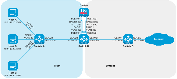
|
Device |
Interface |
IP address |
Device |
Interface |
IP address |
|
Host A |
N/A |
192.168.10.15/24 |
Device |
RAGG1.100 |
10.1.1.2/30 |
|
Host B |
N/A |
192.168.20.15/24 |
|
RAGG1.200 |
10.1.1.5/30 |
|
Host C |
N/A |
192.168.30.15/24 |
Switch C |
|
10.1.1.6/30 |
|
Switch A |
GE1/0/4 |
10.1.1.1/30 |
|
GE1/0/2 |
20.1.1.1/24 |
|
|
VLAN Interface 10 |
192.168.10.1/24 |
|
|
|
|
|
Vlan-interface 20 |
192.168.20.1/24 |
|
|
|
|
|
VLAN Interface 30 |
192.168.30.1/24 |
|
|
|
Procedures
Configuring Switch A
Create VLAN 10, VLAN 20, and VLAN 30, and add GigabitEthernet1/0/1, GigabitEthernet1/0/2, and GigabitEthernet1/0/3 to VLAN 10, VLAN 20, and VLAN 30 respectively.
<SwitchA> system-view
[SwitchA] vlan 10
[SwitchA-vlan10] port gigabitethernet 1/0/1
[SwitchA-vlan10] quit
[SwitchA] vlan 20
[SwitchA-vlan20] port gigabitethernet 1/0/2
[SwitchA-vlan20] quit
[SwitchA] vlan 30
[SwitchA-vlan30] port gigabitethernet 1/0/3
[SwitchA-vlan30] quit
Create interfaces for VLAN 10, VLAN 20, and VLAN 30 and configure the IP address.
[SwitchA] interface vlan-interface 10
[SwitchA-Vlan-interface10] ip address 192.168.10.1 24
[SwitchA-Vlan-interface10] quit
[SwitchA] interface vlan-interface 20
[SwitchA-Vlan-interface20] ip address 192.168.20.1 24
[SwitchA-Vlan-interface20] quit
[SwitchA] interface vlan-interface 30
[SwitchA-Vlan-interface30] ip address 192.168.30.1 24
[SwitchA-Vlan-interface30] quit
Switch GigabitEthernet1/0/4 to layer 3 mode and configure its IP address.
[SwitchA] interface gigabitethernet 1/0/4
[SwitchA-GigabitEthernet1/0/4] port link-mode route
The configuration of the interface will be restored to the default. Continue? [Y] :y
[SwitchA-GigabitEthernet1/0/4] ip address 10.1.1.1 30
[SwitchA-GigabitEthernet1/0/4] quit
Guide for configuring static route to direct upstream traffic forwarding.
[SwitchA] ip route-static 20.1.1.0 24 10.1.1.2
Configuring Switch B
Create VLAN 100 and VLAN 200, and add GigabitEthernet1/0/1 and GigabitEthernet1/0/2 to VLAN 100 and VLAN 200, respectively.
<SwitchB> system-view
[SwitchB] vlan 100
[SwitchB-vlan100] port gigabitethernet 1/0/1
[SwitchB-vlan100] quit
[SwitchB] vlan 200
[SwitchB-vlan200] port gigabitethernet 1/0/2
[SwitchB-vlan200] quit
Create a Layer 2 aggregation interface 1 as a Trunk port, allowing messages from VLAN 100 and VLAN 200 to pass through.
[SwitchB] interface bridge-aggregation 1
[SwitchB-Bridge-Aggregation1] port link-type trunk
[SwitchB-Bridge-Aggregation1] port trunk permit vlan 100 200
[SwitchB-Bridge-Aggregation1] quit
Add ports FortyGigE2/0/1 and FortyGigE2/0/2 to the aggregation group 1.
[SwitchB] interface range fortygige 2/0/1 fortygige 2/0/2
[SwitchB-if-range] port link-aggregation group 1
[SwitchB-if-range] quit
Configuring Switch C
Switch GigabitEthernet1/0/1 to Layer 3 mode and configure its IP address.
<SwitchC> system-view
[SwitchC] interface gigabitethernet 1/0/1
[SwitchC-GigabitEthernet1/0/1] port link-mode route
The configuration of the interface will be restored to the default. Continue? [Y] :y
[SwitchC-GigabitEthernet1/0/1] ip address 10.1.1.6 30
[SwitchC-GigabitEthernet1/0/1] quit
Switch the working mode of GigabitEthernet1/0/2 to Layer 3 mode and configure the IP address.
[SwitchC] interface gigabitethernet 1/0/2
[SwitchC-GigabitEthernet1/0/2] port link-mode route
The configuration of the interface will be restored to the default. Continue? [Y] :y
[SwitchC-GigabitEthernet1/0/2] ip address 20.1.1.1 24
[SwitchC-GigabitEthernet1/0/2] quit
Guidance for configuring the static route directs downstream traffic forwarding.
[SwitchC] ip route-static 192.168.10.0 24 10.1.1.5
[SwitchC] ip route-static 192.168.20.0 24 10.1.1.5
[SwitchC] ip route-static 192.168.30.0 24 10.1.1.5
Configure Device
Create a Layer 3 aggregation interface 1.
<Device> system-view
[Device] interface route-aggregation 1
[Device-Route-Aggregation1] quit
Create Layer 3 aggregation subinterfaces Route-Aggregation1.100 and Route-Aggregation1.200, enable the Dot1q termination function, separately terminating VLAN 100 and VLAN 200, and configure the interface IP.
[Device] interface route-aggregation 1.100
[Device-Route-Aggregation1.100] vlan-type dot1q vid 100
[Device-Route-Aggregation1.100] ip address 10.1.1.2 30
[Device-Route-Aggregation1.100] quit
[Device] interface route-aggregation 1.200
[Device-Route-Aggregation1.200] vlan-type dot1q vid 200
[Device-Route-Aggregation1.200] ip address 10.1.1.5 30
[Device-Route-Aggregation1.200] quit
Add FortyGigE1/0/1 and FortyGigE1/0/2 to aggregation group 1.
[Device] interface range fortygige 1/0/1 fortygige 1/0/2
[Device-if-range] port link-aggregation group 1
[Device-if-range] quit
Add Route-Aggregation1.100 and Route-Aggregation1.200 to the security zones Trust and Untrust, respectively.
[Device] security-zone name trust
[Device-security-zone-Trust] import interface route-aggregation 1.100
[Device-security-zone-Trust] quit
[Device] security-zone name untrust
[Device-security-zone-Untrust] import interface route-aggregation 1.200
[Device-security-zone-Untrust] quit
Configure the security policy to allow inter-domain messages to pass.
[Device] security-policy ip
[Device-security-policy-ip] rule name trust-untrust
[Device-security-policy-ip-0-trust-untrust] action pass
[Device-security-policy-ip-0-trust-untrust] source-zone trust
[Device-security-policy-ip-0-trust-untrust] destination-zone untrust
[Device-security-policy-ip-0-trust-untrust] quit
[Device-security-policy-ip] rule name untrust-trust
[Device-security-policy-ip-1-untrust-trust] action pass
[Device-security-policy-ip-1-untrust-trust] source-zone untrust
[Device-security-policy-ip-1-untrust-trust] destination-zone trust
[Device-security-policy-ip-1-untrust-trust] quit
[Device-security-policy-ip] quit
The guide sets up a static route to direct both upstream and downstream traffic forwarding.
[Device] ip route-static 192.168.10.0 24 10.1.1.1
[Device] ip route-static 192.168.20.0 24 10.1.1.1
[Device] ip route-static 192.168.30.0 24 10.1.1.1
[Device] ip route-static 20.1.1.0 24 10.1.1.6
Verifying the configuration
Host A tests the connectivity to the Internet by pinging, and it can successfully ping the Internet address 20.1.1.1.
C:\>ping 20.1.1.1
Pinging 20.1.1.1 with 32 bytes of data:
Reply from 20.1.1.1: bytes=32 time=3ms TTL=254
Reply from 20.1.1.1: bytes=32 time=2ms TTL=254
Reply from 20.1.1.1: bytes=32 time=1ms TTL=254
Reply from 20.1.1.1: bytes=32 time=2ms TTL=254
Ping statistics for 20.1.1.1:
Packets: Sent = 4, Received = 4, Lost = 0 (0% loss),
Approximate round trip times in milli-seconds:
Minimum = 1ms, Maximum = 3ms, Average = 2ms
On Host B, a connectivity test to the Internet through a ping test can be executed successfully. It is possible to ping the Internet address 20.1.1.1.
C:\>ping 20.1.1.1
Pinging 20.1.1.1 with 32 bytes of data:
Reply from 20.1.1.1: bytes=32 time=3ms TTL=254
Reply from 20.1.1.1: bytes=32 time=2ms TTL=254
Reply from 20.1.1.1: bytes=32 time=1ms TTL=254
Reply from 20.1.1.1: bytes=32 time=2ms TTL=254
Ping statistics for 20.1.1.1:
Packets: Sent = 4, Received = 4, Lost = 0 (0% loss),
Approximate round trip times in milli-seconds:
Minimum = 1ms, Maximum = 3ms, Average = 2ms
Host C is conducting a connectivity test to the Internet by pinging it. It has successfully pinged the Internet address 20.1.1.1.
C:\>ping 20.1.1.1
Pinging 20.1.1.1 with 32 bytes of data:
Reply from 20.1.1.1: bytes=32 time=3ms TTL=254
Reply from 20.1.1.1: bytes=32 time=2ms TTL=254
Reply from 20.1.1.1: bytes=32 time=1ms TTL=254
Reply from 20.1.1.1: bytes=32 time=2ms TTL=254
Ping statistics for 20.1.1.1:
Packets: Sent = 4, Received = 4, Lost = 0 (0% loss),
Approximate round trip times in milli-seconds:
Minimum = 1ms, Maximum = 3ms, Average = 2ms
Check the session table on the Device, there is a session table between the Host and 20.1.1.1.
[Device] display session table ipv4
Slot 1:
Initiator:
Source IP/port: 192.168.10.15/12005
Destination IP/port: 20.1.1.1/2048
DS-Lite tunnel peer: -
VPN instance/VLAN ID/Inline ID: -/-/-
Protocol: ICMP(1)
Inbound interface: Route-Aggregation1.100
Source security zone: Trust
Initiator:
Source IP/port: 192.168.20.15/12005
Destination IP/port: 20.1.1.1/2048
DS-Lite tunnel peer: -
VPN instance/VLAN ID/Inline ID: -/-/-
Protocol: ICMP(1)
Inbound interface: Route-Aggregation1.100
Source security zone: Trust
Initiator:
Source IP/port: 192.168.30.15/12005
Destination IP/port: 20.1.1.1/2048
DS-Lite tunnel peer: -
VPN instance/VLAN ID/Inline ID: -/-/-
Protocol: ICMP(1)
Inbound interface: Route-Aggregation1.100
Source security zone: Trust
Configuration file
Switch A
#
vlan 10
#
vlan 20
#
vlan 30
#
interface Vlan-interface10
ip address 192.168.10.1 255.255.255.0
#
interface Vlan-interface20
ip address 192.168.20.1 255.255.255.0
#
interface Vlan-interface30
ip address 192.168.30.1 255.255.255.0
#
interface GigabitEthernet1/0/4
port link-mode route
ip address 10.1.1.1 255.255.255.252
#
interface GigabitEthernet1/0/1
port access vlan 10
#
interface GigabitEthernet1/0/2
port access vlan 20
#
interface GigabitEthernet1/0/3
port access vlan 30
#
ip route-static 20.1.1.0 24 10.1.1.2
#
Switch B
#
vlan 100
#
vlan 200
#
interface Bridge-Aggregation1
port link-type trunk
port trunk permit vlan 100 200
#
interface FortyGigE2/0/1
port link-aggregation group 1
#
interface FortyGigE2/0/2
port link-aggregation group 1
#
interface GigabitEthernet1/0/1
port access vlan 100
#
interface GigabitEthernet1/0/2
port access vlan 200
#
Switch C
#
interface GigabitEthernet1/0/1
port link-mode route
ip address 10.1.1.6 255.255.255.252
#
interface GigabitEthernet1/0/2
port link-mode route
ip address 20.1.1.1 255.255.255.0
#
ip route-static 192.168.10.0 24 10.1.1.5
ip route-static 192.168.20.0 24 10.1.1.5
ip route-static 192.168.30.0 24 10.1.1.5
#
Device
#
interface Route-Aggregation1
#
interface Route-Aggregation1.100
ip address 10.1.1.2 255.255.255.252
vlan-type dot1q vid 100
#
interface Route-Aggregation1.200
ip address 10.1.1.5 255.255.255.252
vlan-type dot1q vid 200
#
interface FortyGigE1/0/1
port link-aggregation group 1
#
interface FortyGigE1/0/2
port link-aggregation group 1
#
security-zone name Trust
import interface Route-Aggregation1.100
#
security-zone name Untrust
import interface Route-Aggregation1.200
#
ip route-static 20.1.1.0 24 10.1.1.6
ip route-static 192.168.10.0 24 10.1.1.1
ip route-static 192.168.20.0 24 10.1.1.1
ip route-static 192.168.30.0 24 10.1.1.1
#
security-policy ip
rule 0 name trust-untrust
action pass
source-zone trust
destination-zone untrust
rule 1 name untrust-trust
action pass
source-zone untrust
destination-zone trust
#
Deploy the SecBlade module in a side-mounted configuration for Layer 2 diversion
Network configuration
Host A, Host B, and Host C communicate with the Internet through access switch Switch A, aggregation switch Switch B, and core switch Switch C. For security reasons, a SecBlade module Device needs to be deployed on the aggregation switch Switch B to provide security protection. The application requirements are as follows:
· Switch A assigns Host A, Host B, and Host C to VLAN 10, VLAN 20, and VLAN 30 respectively, passing through the traffic between the Hosts and the Internet.
· Switch B divides its uplink and downlink service ports into VLAN 10, VLAN 20, and VLAN 30. The interconnection port with Device is allocated into VLAN 10, VLAN 20, and VLAN 30. QoS redirects the uplink and downlink traffic between Host and Internet to Device. The return traffic is redirected in the opposite orientation by QoS.
· The device's uplink and downlink service ports are segmented on VLAN 10, VLAN 20, and VLAN 30, allowing for the transparent transmission of traffic between the host and the Internet.
· Switch C serves as the gateway for Host A, Host B, and Host C, consulting the routing table to forward traffic between the hosts and the Internet.
Figure 24 Side-mounted deployment of SecBlade module and the network diagram of the Layer 2 diversion group
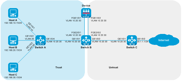
|
Device |
Interface |
IP address |
|
Host A |
N/A |
192.168.10.15/24 |
|
Host B |
N/A |
192.168.20.15/24 |
|
Host C |
N/A |
192.168.30.15/24 |
|
Switch C |
Vlan-interface10 |
192.168.10.1/24 |
|
|
Vlan-interface20 |
192.168.20.1/24 |
|
|
Vlan-interface30 |
192.168.30.1/24 |
|
|
GE1/0/2 |
20.1.1.1/24 |
Procedures
Configuring Switch A
Create VLAN 10, VLAN 20, and VLAN 30. Add GigabitEthernet1/0/1, GigabitEthernet1/0/2, and GigabitEthernet1/0/3 to VLAN 10, VLAN 20, and VLAN 30, respectively.
<SwitchA> system-view
[SwitchA] vlan 10
[SwitchA-vlan10] port gigabitethernet 1/0/1
[SwitchA-vlan10] quit
[SwitchA] vlan 20
[SwitchA-vlan20] port gigabitethernet 1/0/2
[SwitchA-vlan20] quit
[SwitchA] vlan 30
[SwitchA-vlan30] port gigabitethernet 1/0/3
[SwitchA-vlan30] quit
Configure the link type of GigabitEthernet1/0/4 as Trunk, and allow the messages from VLAN 10, VLAN 20, and VLAN 30 to pass through.
[SwitchA] interface gigabitethernet 1/0/4
[SwitchA-GigabitEthernet1/0/4] port link-type trunk
[SwitchA-GigabitEthernet1/0/4] port trunk permit vlan 10 20 30
[SwitchA-GigabitEthernet1/0/4] quit
Configuring Switch B
Create VLAN 10, VLAN 20, and VLAN 30.
<SwitchB> system-view
[SwitchB] vlan 10
[SwitchB-vlan10] quit
[SwitchB] vlan 20
[SwitchB-vlan20] quit
[SwitchB] vlan 30
[SwitchB-vlan30] quit
Turn off the MAC address learning function on the FortyGigE2/0/1 and FortyGigE2/0/2 ports to prevent MAC wandering.
[SwitchB] interface range fortygige 2/0/1 fortygige 2/0/2
[SwitchB-if-range] undo mac-address mac-learning enable
[SwitchB-if-range] quit
Turn off the Spanning Tree Protocol (STP) on the FortyGigE2/0/1 and FortyGigE2/0/2 ports (to prevent the STP from having the ability to disable the ports from forwarding and receiving messages).
[SwitchB] interface range fortygige 2/0/1 fortygige 2/0/2
[SwitchB-if-range] undo stp enable
[SwitchB-if-range] quit
Configure the link type for GigabitEthernet1/0/1, FortyGigE2/0/1, FortyGigE2/0/2, and GigabitEthernet1/0/2 as Trunk, and allow packets from VLAN 10, VLAN 20, and VLAN 30 to pass.
[SwitchB] interface range gigabitEthernet 1/0/1 gigabitEthernet 1/0/2 fortygige 2/0/1 fortygige 2/0/2
[SwitchB-if-range] port link-type trunk
[SwitchB-if-range] port trunk permit vlan 10 20 30
[SwitchB-if-range] quit
Define a class to match VLAN 10, VLAN 20, and VLAN 30.
[SwitchB] traffic classifier servicevlan
[SwitchB-classifier-host-out] if-match service-vlan-id 10 20 30
[SwitchB-classifier-host-out] quit
Define the traffic behavior, with the action set to redirect to the corresponding interface.
[SwitchB] traffic behavior gigabitethernet1/0/1
[SwitchB-behavior-gigabitethernet1/0/1] redirect interface gigabitethernet 1/0/1
[SwitchB-behavior-gigabitethernet1/0/1] quit
[SwitchB] traffic behavior gigabitethernet1/0/2
[SwitchB-behavior-gigabitethernet1/0/2] redirect interface gigabitethernet 1/0/2
[SwitchB-behavior-gigabitethernet1/0/2] quit
[SwitchB] traffic behavior fortygige2/0/1
[SwitchB-behavior-fortygige2/0/1] redirect interface fortygige 2/0/1
[SwitchB-behavior-fortygige2/0/1] quit
[SwitchB] traffic behavior fortygige2/0/2
[SwitchB-behavior-fortygige2/0/2] redirect interface fortygige 2/0/2
[SwitchB-behavior-fortygige2/0/2] quit
Define a policy and assign a traffic behavior to a class.
[SwitchB] qos policy gigabitethernet1/0/1
[SwitchB-qospolicy-gigabitethernet1/0/1] classifier servicevlan behavior gigabitethernet1/0/1
[SwitchB-qospolicy-gigabitethernet1/0/1] quit
[SwitchB] qos policy gigabitethernet1/0/2
[SwitchB-qospolicy-gigabitethernet1/0/2] classifier servicevlan behavior gigabitethernet1/0/2
[SwitchB-qospolicy-gigabitethernet1/0/2] quit
[SwitchB] qos policy fortygige2/0/1
[SwitchB-qospolicy-fortygige2/0/1] classifier servicevlan behavior fortygige2/0/1
[SwitchB-qospolicy-fortygige2/0/1] quit
[SwitchB] qos policy fortygige2/0/2
[SwitchB-qospolicy-fortygige2/0/2] classifier servicevlan behavior fortygige2/0/2
[SwitchB-qospolicy-fortygige2/0/2] quit
Apply the policy to the inbound direction of the port.
[SwitchB] interface gigabitethernet 1/0/1
[SwitchB-GigabitEthernet1/0/1] qos apply policy fortygige2/0/1 inbound
[SwitchB-GigabitEthernet1/0/1] quit
[SwitchB] interface gigabitethernet 1/0/2
[SwitchB-GigabitEthernet1/0/2] qos apply policy fortygige2/0/2 inbound
[SwitchB-GigabitEthernet1/0/2] quit
[SwitchB] interface fortygige 2/0/1
[SwitchB-GigabitEthernet1/0/1] qos apply policy gigabitethernet1/0/1 inbound
[SwitchB-GigabitEthernet1/0/1] quit
[SwitchB] interface fortygige 2/0/2
[SwitchB-GigabitEthernet1/0/2] qos apply policy gigabitethernet1/0/2 inbound
[SwitchB-GigabitEthernet1/0/2] quit
Configuring Switch C
Create VLAN 10, VLAN 20, and VLAN 20.
<SwitchC> system-view
[SwitchC] vlan 10
[SwitchC-vlan10] quit
[SwitchC] vlan 20
[SwitchC-vlan20] quit
[SwitchC] vlan 30
[SwitchC-vlan30] quit
Configure the link type of GigabitEthernet1/0/1 as Trunk, and allow packets from VLAN 10, VLAN 20, and VLAN 20 to pass through.
[SwitchC] interface gigabitethernet 1/0/1
[SwitchC-GigabitEthernet1/0/1] port link-type trunk
[SwitchC-GigabitEthernet1/0/1] port trunk permit vlan 10 20 30
[SwitchC-GigabitEthernet1/0/1] quit
Create VLAN 10, VLAN 20, and VLAN 30 interfaces, and configure the IP address for the VLAN interfaces.
[SwitchC] interface vlan-interface 10
[SwitchC-Vlan-interface10] ip address 192.168.10.1 24
[SwitchC-Vlan-interface10] quit
[SwitchC] interface vlan-interface 20
[SwitchC-Vlan-interface20] ip address 192.168.20.1 24
[SwitchC-Vlan-interface20] quit
[SwitchC] interface vlan-interface 30
[SwitchC-Vlan-interface30] ip address 192.168.30.1 24
[SwitchC-Vlan-interface30] quit
Switch the working mode of GigabitEthernet1/0/2 to Layer 3, and configure the IP address.
[SwitchC] interface gigabitethernet 1/0/2
[SwitchC-GigabitEthernet1/0/2] port link-mode route
The configuration of the interface will be restored to the default. Continue? [Y]:y
[SwitchC-GigabitEthernet1/0/2] ip address 20.1.1.1 24
[SwitchC-GigabitEthernet1/0/2] quit
Configure Device
Create VLAN10, VLAN20, and VLAN30.
<Device> system-view
[Device] vlan 10
[Device-vlan10] quit
[Device] vlan 20
[Device-vlan20] quit
[Device] vlan 30
[Device-vlan30] quit
Switch the operating mode of FortyGigE1/0/1 and FortyGigE1/0/2 to layer 2 mode.
[Device] interface range fortygige 1/0/1 fortygige 1/0/2
[Device-if-range] port link-mode bridge
[Device-if-range] quit
Configure the link types of FortyGigE1/0/1 and FortyGigE1/0/2 as Trunk, and allow VLAN 10, VLAN 20, and VLAN 30 packets to pass through.
[Device] interface range fortygige 1/0/1 fortygige 1/0/2
[Device-if-range] port link-type trunk
[Device-if-range] port trunk permit vlan 10 20 30
[Device-if-range] quit
Add VLAN10, VLAN20, and VLAN30 of FortyGigE1/0/1 to the security domain Trust, and VLAN10, VLAN20, and VLAN30 of FortyGigE1/0/2 to the security domain Untrust.
[Device] security-zone name trust
[Device-security-zone-Trust] import interface fortygige 1/0/1 vlan 10 20 30
[Device-security-zone-Trust] quit
[Device] security-zone name untrust
[Device-security-zone-Untrust] import interface fortygige 1/0/2 vlan 10 20 30
[Device-security-zone-Untrust] quit
Configure the security policy to allow inter-domain messages to pass.
[Device] security-policy ip
[Device-security-policy-ip] rule name trust-untrust
[Device-security-policy-ip-0-trust-untrust] action pass
[Device-security-policy-ip-0-trust-untrust] source-zone trust
[Device-security-policy-ip-0-trust-untrust] destination-zone untrust
[Device-security-policy-ip-0-trust-untrust] quit
[Device-security-policy-ip] rule name untrust-trust
[Device-security-policy-ip-1-untrust-trust] action pass
[Device-security-policy-ip-1-untrust-trust] source-zone untrust
[Device-security-policy-ip-1-untrust-trust] destination-zone trust
[Device-security-policy-ip-1-untrust-trust] quit
[Device-security-policy-ip] quit
Verifying the configuration
# Host A is ping testing the connectivity to the Internet. It can successfully ping the Internet address 20.1.1.1.
C:\>ping 20.1.1.1
Pinging 20.1.1.1 with 32 bytes of data:
Reply from 20.1.1.1: bytes=32 time=3ms TTL=254
Reply from 20.1.1.1: bytes=32 time=2ms TTL=254
Reply from 20.1.1.1: bytes=32 time=1ms TTL=254
Reply from 20.1.1.1: bytes=32 time=2ms TTL=254
Ping statistics for 20.1.1.1:
Packets: Sent = 4, Received = 4, Lost = 0 (0% loss),
Approximate round trip times in milli-seconds:
Minimum = 1ms, Maximum = 3ms, Average = 2ms
Host B is testing the connectivity to the Internet, with the ability to successfully ping the Internet address 20.1.1.1.
C:\>ping 20.1.1.1
Pinging 20.1.1.1 with 32 bytes of data:
Reply from 20.1.1.1: bytes=32 time=3ms TTL=254
Reply from 20.1.1.1: bytes=32 time=2ms TTL=254
Reply from 20.1.1.1: bytes=32 time=1ms TTL=254
Reply from 20.1.1.1: bytes=32 time=2ms TTL=254
Ping statistics for 20.1.1.1:
Packets: Sent = 4, Received = 4, Lost = 0 (0% loss),
Approximate round trip times in milli-seconds:
Minimum = 1ms, Maximum = 3ms, Average = 2ms
On the device, check the session table. There exists a session table between the host and 20.1.1.1.
[Device] display session table ipv4
Slot 1:
Initiator:
Source IP/port: 192.168.10.15/12005
Destination IP/port: 20.1.1.1/2048
DS-Lite tunnel peer: -
VPN instance/VLAN ID/Inline ID: -/10/-
Protocol: ICMP(1)
Inbound interface: FortyGigE1/0/1
Source security zone: Trust
Initiator:
Source IP/port: 192.168.20.15/12005
Destination IP/port: 20.1.1.1/2048
DS-Lite tunnel peer: -
VPN instance/VLAN ID/Inline ID: -/20/-
Protocol: ICMP(1)
Inbound interface: FortyGigE1/0/1
Source security zone: Trust
Initiator:
Source IP/port: 192.168.30.15/12005
Destination IP/port: 20.1.1.1/2048
DS-Lite tunnel peer: -
VPN instance/VLAN ID/Inline ID: -/30/-
Protocol: ICMP(1)
Inbound interface: FortyGigE1/0/1
Source security zone: Trust
Configuration file
Switch A
#
vlan 10
#
vlan 20
#
vlan 30
#
interface GigabitEthernet1/0/1
port access vlan 10
#
interface GigabitEthernet1/0/2
port access vlan 20
#
interface GigabitEthernet1/0/3
port access vlan 30
#
interface GigabitEthernet1/0/4
port link-type trunk
port trunk permit vlan 10 20 30
#
Switch B
#
vlan 10
#
vlan 20
#
vlan 30
#
traffic classifier servicevlan
if-match service-vlan-id 10 20 30
#
traffic behavior gigabitethernet1/0/1
redirect interface gigabitethernet 1/0/1
#
traffic behavior gigabitethernet1/0/2
redirect interface gigabitethernet 1/0/2
#
traffic behavior fortygige2/0/1
redirect interface fortygige 2/0/1
#
traffic behavior fortygige2/0/2
redirect interface fortygige 2/0/2
#
qos policy gigabitethernet1/0/1
classifier servicevlan behavior gigabitethernet1/0/1
#
qos policy gigabitethernet1/0/2
classifier servicevlan behavior gigabitethernet1/0/2
#
qos policy fortygige2/0/1
classifier servicevlan behavior fortygige2/0/1
#
qos policy fortygige2/0/2
classifier servicevlan behavior fortygige2/0/2
#
interface FortyGigE2/0/1
port link-type trunk
port trunk permit vlan 10 20 30
undo stp enable
undo mac-address mac-learning enable
qos apply policy gigabitethernet1/0/1 inbound
#
interface FortyGigE2/0/2
port link-type trunk
port trunk permit vlan 10 20 30
undo stp enable
undo mac-address mac-learning enable
qos apply policy gigabitethernet1/0/2 inbound
#
interface GigabitEthernet1/0/1
port link-type trunk
port trunk permit vlan 10 20 30
qos apply policy fortygige2/0/1 inbound
#
interface GigabitEthernet1/0/2
port link-type trunk
port trunk permit vlan 10 20 30
qos apply policy fortygige2/0/2 inbound
#
Switch C
#
vlan 10
#
vlan 20
#
vlan 30
#
interface Vlan-interface10
ip address 192.168.10.1 255.255.255.0
#
interface Vlan-interface20
ip address 192.168.20.1 255.255.255.0
#
interface Vlan-interface30
ip address 192.168.30.1 255.255.255.0
#
interface GigabitEthernet1/0/2
port link-mode route
ip address 20.1.1.1 255.255.255.0
#
interface GigabitEthernet1/0/1
port link-type trunk
port trunk permit vlan 10 20 30
#
Device
#
vlan 10
#
vlan 20
#
vlan 30
#
interface FortyGigE1/0/1
port link-mode bridge
port link-type trunk
port trunk permit vlan 10 20 30
#
interface FortyGigE1/0/2
port link-mode bridge
port link-type trunk
port trunk permit vlan 10 20 30
#
security-zone name Trust
import interface FortyGigE1/0/1 vlan 10 20 30
#
security-zone name Untrust
import interface FortyGigE1/0/2 vlan 10 20 30
#
security-policy ip
rule 0 name trust-untrust
action pass
source-zone trust
destination-zone untrust
rule 1 name untrust-trust
action pass
source-zone untrust
destination-zone trust
#
Deploy SecBlade module in a transparent straight path deployment
Network configuration
Host A, Host B, and Host C communicate with the Internet through access switch Switch A, aggregation switch Switch B, and core switch Switch C. For security reasons, a SecBlade module Device needs to be deployed on aggregation switch Switch B for protection. The application requirements are as follows:
· Switch A assigns Host A, Host B, and Host C to VLAN 10, VLAN 20, and VLAN 30 respectively, and transparently transmits the traffic between the Host and the Internet.
· Switch B categorizes the downstream service ports into VLAN 10, VLAN 20, and VLAN 30, and the upstream service ports into VLAN 40, VLAN 50, and VLAN 60. The interconnection port with the Device is categorized into VLAN 10, VLAN 20, VLAN 30, VLAN 40, VLAN 50, and VLAN 60. It transmits the traffic between the Host and Internet to the Device upstream and downstream.
· The device separates downstream traffic into VLAN 10, VLAN 20, and VLAN 30, while upstream traffic is divided into VLAN 40, VLAN 50, and VLAN 60. The device forwards traffic between the Host and the Internet across VLANs.
· Switch C serves as the gateway for Host A, Host B, and Host C, forwarding traffic between the Hosts and the Internet by consulting the routing table.
Figure 25 Transparent Direct Path Deployment of SecBlade module Group Networking Diagram

|
Device |
Interface |
IP address |
|
Host A |
N/A |
192.168.10.15/24 |
|
Host B |
N/A |
192.168.20.15/24 |
|
Host C |
N/A |
192.168.30.15/24 |
|
Switch C |
Vlan-interface40 |
192.168.10.1/24 |
|
|
Vlan-interface50 |
192.168.20.1/24 |
|
|
Vlan-interface60 |
192.168.30.1/24 |
|
|
GE1/0/2 |
20.1.1.1/24 |
Procedures
Configuring Switch A
Create VLAN 10, VLAN 20, and VLAN 30. Add GigabitEthernet1/0/1, GigabitEthernet1/0/2, and GigabitEthernet1/0/3 to VLAN 10, VLAN 20, and VLAN 30, respectively.
<SwitchA> system-view
[SwitchA] vlan 10
[SwitchA-vlan10] port gigabitethernet 1/0/1
[SwitchA-vlan10] quit
[SwitchA] vlan 20
[SwitchA-vlan20] port gigabitethernet 1/0/2
[SwitchA-vlan20] quit
[SwitchA] vlan 30
[SwitchA-vlan30] port gigabitethernet 1/0/3
[SwitchA-vlan30] quit
Configure the link type of GigabitEthernet1/0/4 as Trunk, and allow packets from VLAN 10, VLAN 20, and VLAN 30 to pass.
[SwitchA] interface gigabitethernet 1/0/4
[SwitchA-GigabitEthernet1/0/4] port link-type trunk
[SwitchA-GigabitEthernet1/0/4] port trunk permit vlan 10 20 30
[SwitchA-GigabitEthernet1/0/4] quit
Configuring Switch B
Create VLAN 10, VLAN 20, VLAN 30, VLAN 40, VLAN 50, and VLAN 60.
<SwitchB> system-view
[SwitchB] vlan 10
[SwitchB-vlan10] quit
[SwitchB] vlan 20
[SwitchB-vlan20] quit
[SwitchB] vlan 30
[SwitchB-vlan30] quit
[SwitchB] vlan 40
[SwitchB-vlan40] quit
[SwitchB] vlan 50
[SwitchB-vlan50] quit
[SwitchB] vlan 60
[SwitchB-vlan60] quit
Configure the link type of GigabitEthernet1/0/1 as Trunk, and allow the messages of VLAN 10, VLAN 20 and VLAN 30 to pass.
[SwitchB] interface gigabitethernet 1/0/1
[SwitchB-GigabitEthernet1/0/1] port link-type trunk
[SwitchB-GigabitEthernet1/0/1] port trunk permit vlan 10 20 30
[SwitchB-GigabitEthernet1/0/1] quit
Configure the link type of GigabitEthernet1/0/2 as Trunk, and allow packets from VLAN 40, VLAN 50, and VLAN 60 to pass through.
[SwitchB] interface gigabitethernet 1/0/2
[SwitchB-GigabitEthernet1/0/2] port link-type trunk
[SwitchB-GigabitEthernet1/0/2] port trunk permit vlan 40 50 60
[SwitchB-GigabitEthernet1/0/2] quit
Create Layer 2 aggregation interface 1 as Trunk port, and allow packets of VLAN 10, VLAN 20, VLAN 30, VLAN 40, VLAN 50, and VLAN 60 to pass through.
[SwitchB] interface bridge-aggregation 1
[SwitchB-Bridge-Aggregation1] port link-type trunk
[SwitchB-Bridge-Aggregation1] port trunk permit vlan 10 20 30 40 50 60
[SwitchB-Bridge-Aggregation1] quit
Add ports FortyGigE2/0/1 and FortyGigE2/0/2 to the aggregation group 1.
[SwitchB] interface range fortygige 2/0/1 fortygige 2/0/2
[SwitchB-if-range] port link-aggregation group 1
[SwitchB-if-range] quit
Configuring Switch C
Create VLAN 40, VLAN 50, and VLAN 60.
<SwitchC> system-view
[SwitchC] vlan 40
[SwitchC-vlan40] quit
[SwitchC] vlan 50
[SwitchC-vlan50] quit
[SwitchC] vlan 60
[SwitchC-vlan60] quit
Configure the link type of GigabitEthernet1/0/1 as Trunk, and allow packets from VLAN 40, VLAN 50, and VLAN 60 to pass.
[SwitchC] interface gigabitethernet 1/0/1
[SwitchC-GigabitEthernet1/0/1] port link-type trunk
[SwitchC-GigabitEthernet1/0/1] port trunk permit vlan 40 50 60
[SwitchC-GigabitEthernet1/0/1] quit
Create VLAN 40, VLAN 50 and VLAN 60 interfaces and configure the IP address of the VLAN interface.
[SwitchC] interface vlan-interface 40
[SwitchC-Vlan-interface40] ip address 192.168.10.1 24
[SwitchC-Vlan-interface40] quit
[SwitchC] interface vlan-interface 50
[SwitchC-Vlan-interface50] ip address 192.168.20.1 24
[SwitchC-Vlan-interface50] quit
[SwitchC] interface vlan-interface 60
[SwitchC-Vlan-interface60] ip address 192.168.30.1 24
[SwitchC-Vlan-interface60] quit
Switch the working mode of GigabitEthernet1/0/2 to stratum three, and configure the IP address.
[SwitchC] interface gigabitethernet 1/0/2
[SwitchC-GigabitEthernet1/0/2] port link-mode route
The configuration of the interface will be restored to the default. Continue? [Y]:y
[SwitchC-GigabitEthernet1/0/2] ip address 20.1.1.1 24
[SwitchC-GigabitEthernet1/0/2] quit
Configure Device
Create VLAN10, VLAN20, VLAN30, VLAN40, VLAN50, and VLAN60.
<Device> system-view
[Device] vlan 10
[Device-vlan10] quit
[Device] vlan 20
[Device-vlan20] quit
[Device] vlan 30
[Device-vlan30] quit
[Device] vlan 40
[Device-vlan40] quit
[Device] vlan 50
[Device-vlan50] quit
[Device] vlan 60
[Device-vlan60] quit
Create a Layer 2 aggregation interface 1 as Trunk port, and allow passage of packets from VLAN 10, VLAN 20, VLAN 30, VLAN 40, VLAN 50, and VLAN 60.
[Device] interface bridge-aggregation 1
[Device-Bridge-Aggregation1] port link-type trunk
[Device-Bridge-Aggregation1] port trunk permit vlan 10 20 30 40 50 60
[Device-Bridge-Aggregation1] quit
Switch the working mode of FortyGigE1/0/1 and FortyGigE1/0/2 to Layer 2, and add them to the aggregation group 1.
[Device] interface range fortygige 1/0/1 fortygige 1/0/2
[Device-if-range] port link-mode bridge
[Device-if-range] port link-aggregation group 1
[Device-if-range] quit
Add VLAN10, VLAN20, and VLAN30 to the security domain Trust, and VLAN40, VLAN50, and VLAN60 to the security domain Untrust.
[Device] security-zone name trust
[Device-security-zone-Trust] import vlan 10 20 30
[Device-security-zone-Trust] quit
[Device] security-zone name untrust
[Device-security-zone-Untrust] import vlan 40 50 60
[Device-security-zone-Untrust] quit
Configure the security policy to allow inter-domain messages to pass through.
[Device] security-policy ip
[Device-security-policy-ip] rule name trust-untrust
[Device-security-policy-ip-0-trust-untrust] action pass
[Device-security-policy-ip-0-trust-untrust] source-zone trust
[Device-security-policy-ip-0-trust-untrust] destination-zone untrust
[Device-security-policy-ip-0-trust-untrust] quit
[Device-security-policy-ip] rule name untrust-trust
[Device-security-policy-ip-1-untrust-trust] action pass
[Device-security-policy-ip-1-untrust-trust] source-zone untrust
[Device-security-policy-ip-1-untrust-trust] destination-zone trust
[Device-security-policy-ip-1-untrust-trust] quit
[Device-security-policy-ip] quit
Create forwarding instances Bridge 1, Bridge 2, and Bridge 3 for cross-VLAN forwarding mode, and add the VLANs that need intercommunication to each instance.
[Device] bridge 1 inter-vlan
[Device-bridge-1-inter-vlan] add vlan 10 40
[Device-bridge-1-inter-vlan] quit
[Device] bridge 2 inter-vlan
[Device-bridge-2-inter-vlan] add vlan 20 50
[Device-bridge-2-inter-vlan] quit
[Device] bridge 3 inter-vlan
[Device-bridge-3-inter-vlan] add vlan 30 60
[Device-bridge-3-inter-vlan] quit
Verifying the configuration
Host A performs a ping test to check the internet connectivity and successfully pings the Internet address 20.1.1.1.
C:\>ping 20.1.1.1
Pinging 20.1.1.1 with 32 bytes of data:
Reply from 20.1.1.1: bytes=32 time=3ms TTL=254
Reply from 20.1.1.1: bytes=32 time=2ms TTL=254
Reply from 20.1.1.1: bytes=32 time=1ms TTL=254
Reply from 20.1.1.1: bytes=32 time=2ms TTL=254
Ping statistics for 20.1.1.1:
Packets: Sent = 4, Received = 4, Lost = 0 (0% loss),
Approximate round trip times in milli-seconds:
Minimum = 1ms, Maximum = 3ms, Average = 2ms
Host B is conducting a ping test for Internet
connectivity and can successfully ping the Internet address 20.1.1.1.
C:\>ping 20.1.1.1
Pinging 20.1.1.1 with 32 bytes of data:
Reply from 20.1.1.1: bytes=32 time=3ms TTL=254
Reply from 20.1.1.1: bytes=32 time=2ms TTL=254
Reply from 20.1.1.1: bytes=32 time=1ms TTL=254
Reply from 20.1.1.1: bytes=32 time=2ms TTL=254
Ping statistics for 20.1.1.1:
Packets: Sent = 4, Received = 4, Lost = 0 (0% loss),
Approximate round trip times in milli-seconds:
Minimum = 1ms, Maximum = 3ms, Average = 2ms
# On Host C, the connectivity to the Internet is being tested by pinging. The Internet address 20.1.1.1 can be successfully reached by pinging.
C:\>ping 20.1.1.1
Pinging 20.1.1.1 with 32 bytes of data:
Reply from 20.1.1.1: bytes=32 time=3ms TTL=254
Reply from 20.1.1.1: bytes=32 time=2ms TTL=254
Reply from 20.1.1.1: bytes=32 time=1ms TTL=254
Reply from 20.1.1.1: bytes=32 time=2ms TTL=254
Ping statistics for 20.1.1.1:
Packets: Sent = 4, Received = 4, Lost = 0 (0% loss),
Approximate round trip times in milli-seconds:
Minimum = 1ms, Maximum = 3ms, Average = 2ms
Check the session table on the Device, a session table exists between the Host and 20.1.1.1.
[Device] display session table ipv4
Slot 1:
Initiator:
Source IP/port: 192.168.10.15/12005
Destination IP/port: 20.1.1.1/2048
DS-Lite tunnel peer: -
VPN instance/VLAN ID/Inline ID: -/10/-
Protocol: ICMP(1)
Inbound interface: FortyGigE1/0/1
Source security zone: Trust
Initiator:
Source IP/port: 192.168.20.15/12005
Destination IP/port: 20.1.1.1/2048
DS-Lite tunnel peer: -
VPN instance/VLAN ID/Inline ID: -/20/-
Protocol: ICMP(1)
Inbound interface: FortyGigE1/0/1
Source security zone: Trust
Initiator:
Source IP/port: 192.168.30.15/12005
Destination IP/port: 20.1.1.1/2048
DS-Lite tunnel peer: -
VPN instance/VLAN ID/Inline ID: -/30/-
Protocol: ICMP(1)
Inbound interface: FortyGigE1/0/1
Source security zone: Trust
Configuration file
Switch A
#
vlan 10
#
vlan 20
#
vlan 30
#
interface GigabitEthernet1/0/1
port access vlan 10
#
interface GigabitEthernet1/0/2
port access vlan 20
#
interface GigabitEthernet1/0/3
port access vlan 30
#
interface GigabitEthernet1/0/4
port link-type trunk
port trunk permit vlan 10 20 30
#
Switch B
#
vlan 10
#
vlan 20
#
vlan 30
#
vlan 40
#
vlan 50
#
vlan 60
#
interface Bridge-Aggregation1
port link-type trunk
port trunk permit vlan 10 20 30 40 50 60
#
interface FortyGigE2/0/1
port link-aggregation group 1
#
interface FortyGigE2/0/2
port link-aggregation group 1
#
interface GigabitEthernet1/0/1
port link-type trunk
port trunk permit vlan 10 20 30
#
interface GigabitEthernet1/0/2
port link-type trunk
port trunk permit vlan 40 50 60
#
Switch C
#
vlan 40
#
vlan 50
#
vlan 60
#
interface Vlan-interface40
ip address 192.168.10.1 255.255.255.0
#
interface Vlan-interface50
ip address 192.168.20.1 255.255.255.0
#
interface Vlan-interface60
ip address 192.168.30.1 255.255.255.0
#
interface GigabitEthernet1/0/2
port link-mode route
ip address 20.1.1.1 255.255.255.0
#
interface GigabitEthernet1/0/1
port link-type trunk
port trunk permit vlan 40 50 60
#
Device
#
vlan 10
#
vlan 20
#
vlan 30
#
vlan 40
#
vlan 50
#
vlan 60
#
bridge 1 inter-vlan
add vlan 10 40
#
bridge 2 inter-vlan
add vlan 20 50
#
bridge 3 inter-vlan
add vlan 30 60
#
interface Bridge-Aggregation1
port link-type trunk
port trunk permit vlan 10 20 30 40 50 60
#
interface FortyGigE1/0/1
port link-mode bridge
port link-aggregation group 1
#
interface FortyGigE1/0/2
port link-mode bridge
port link-aggregation group 1
#
security-zone name Trust
import vlan 10 20 30
#
security-zone name Untrust
import vlan 40 50 60
#
security-policy ip
rule 0 name trust-untrust
action pass
source-zone trust
destination-zone untrust
rule 1 name untrust-trust
action pass
source-zone untrust
destination-zone trust
#
SecBlade module is deployed in a side-mounted architecture for port mirroring
Network configuration
Host A, Host B, and Host C communicate with the Internet via the access switch Switch A, the aggregation switch Switch B, and the core switch Switch C. For security reasons, it is necessary to deploy a SecBlade module Device on the aggregation switch Switch B to monitor traffic. The application requirements are as follows:
· Switch A segregates Host A, Host B, and Host C into VLAN 10, VLAN 20, and VLAN 30 respectively, acting as their gateway (GW). It forwards the traffic from the Hosts to the Internet by checking the routing table.
· Switch B interfaces with Switch A, Switch B, and Device at a stratum two level, allowing transparent passing of traffic between the Host and the Internet, with one copy of the traffic mirrored to the Device via port mirroring.
· The device interfaces with Switch B at Layer 2, processes the received mirroring traffic for relevant operations, and upon completion, it is discarded by the black hole mode Bridge.
· Switch C interfaces with Switch A at Layer 3, checking the routing table to forward traffic between the Host and the Internet.
Figure 26 Network diagram for the side-mounted deployment of SecBlade module with port mirroring
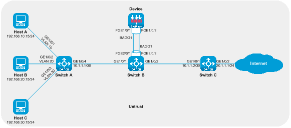
|
Device |
Interface |
IP address |
|
Host A |
N/A |
192.168.10.15/24 |
|
Host B |
N/A |
192.168.20.15/24 |
|
Host C |
N/A |
192.168.30.15/24 |
|
Switch A |
GE1/0/4 |
10.1.1.1/30 |
|
|
VLAN Interface 10 |
192.168.10.1/24 |
|
|
Vlan-interface 20 |
192.168.20.1/24 |
|
|
Vlan-interface 30 |
192.168.30.1/24 |
|
Switch C |
GE1/0/1 |
10.1.1.2/30 |
|
|
GE1/0/2 |
20.1.1.1/24 |
Procedures
Configuring Switch A
Create VLAN 10, VLAN 20, and VLAN 30, and add GigabitEthernet1/0/1, GigabitEthernet1/0/2, and GigabitEthernet1/0/3 to VLAN 10, VLAN 20, and VLAN 30 respectively.
<SwitchA> system-view
[SwitchA] vlan 10
[SwitchA-vlan10] port gigabitethernet 1/0/1
[SwitchA-vlan10] quit
[SwitchA] vlan 20
[SwitchA-vlan20] port gigabitethernet 1/0/2
[SwitchA-vlan20] quit
[SwitchA] vlan 30
[SwitchA-vlan30] port gigabitethernet 1/0/3
[SwitchA-vlan30] quit
Create interfaces for VLAN 10, VLAN 20, and VLAN 30, and configure their IP addresses.
[SwitchA] interface vlan-interface 10
[SwitchA-Vlan-interface10] ip address 192.168.10.1 24
[SwitchA-Vlan-interface10] quit
[SwitchA] interface vlan-interface 20
[SwitchA-Vlan-interface20] ip address 192.168.20.1 24
[SwitchA-Vlan-interface20] quit
[SwitchA] interface vlan-interface 30
[SwitchA-Vlan-interface30] ip address 192.168.30.1 24
[SwitchA-Vlan-interface30] quit
Switch the working mode of GigabitEthernet1/0/4 to layer 3 mode and configure the IP address.
[SwitchA] interface gigabitethernet 1/0/4
[SwitchA-GigabitEthernet1/0/4] port link-mode route
The configuration of the interface will be restored to the default. Continue? [Y] :y
[SwitchA-GigabitEthernet1/0/4] ip address 10.1.1.1 30
[SwitchA-GigabitEthernet1/0/4] quit
Configure the static route to guide the upstream traffic forwarding.
[SwitchA] ip route-static 20.1.1.0 24 10.1.1.2
Configuring Switch B
Create a Layer 2 {aggregation} {interface} 1.
<SwitchB> system-view
[SwitchB] interface bridge-aggregation 1
[SwitchB-Bridge-Aggregation1] quit
Add FortyGigE2/0/1 and FortyGigE2/0/2 into the aggregation group 1.
[SwitchB] interface range fortygige 2/0/1 fortygige 2/0/2
[SwitchB-if-range] port link-aggregation group 1
[SwitchB-if-range] quit
Configure port mirroring, duplicating traffic to Layer 2 aggregation interface 1.
[SwitchB] mirroring-group 1 local
[SwitchB] mirroring-group 1 mirroring-port gigabitethernet 1/0/1 inbound
[SwitchB] mirroring-group 1 mirroring-port gigabitethernet 1/0/2 inbound
[SwitchB] mirroring-group 1 monitor-port bridge-aggregation 1
Configuring Switch C
Switch GigabitEthernet1/0/1 to Layer 3 mode and configure the IP address.
<SwitchC> system-view
[SwitchC] interface gigabitethernet 1/0/1
[SwitchC-GigabitEthernet1/0/1] port link-mode route
The configuration of the interface will be restored to the default. Continue? [Y] :y
[SwitchC-GigabitEthernet1/0/1] ip address 10.1.1.2 30
[SwitchC-GigabitEthernet1/0/1] quit
Change the working mode of GigabitEthernet1/0/2 to layer 3 and configure its IP address.
[SwitchC] interface gigabitethernet 1/0/2
[SwitchC-GigabitEthernet1/0/2] port link-mode route
The configuration of the interface will be restored to the default. Continue? [Y] :y
[SwitchC-GigabitEthernet1/0/2] ip address 20.1.1.1 24
[SwitchC-GigabitEthernet1/0/2] quit
Guide for configuring static route to direct downstream traffic forwarding.
[SwitchC] ip route-static 192.168.10.0 24 10.1.1.1
[SwitchC] ip route-static 192.168.20.0 24 10.1.1.1
[SwitchC] ip route-static 192.168.30.0 24 10.1.1.1
Configure Device
Create an aggregation interface 1 at the Layer 2.
<Device> system-view
[Device] interface bridge-aggregation 1
[Device-Bridge-Aggregation1] quit
Switch the working mode of FortyGigE1/0/1 and FortyGigE1/0/2 to layer 2, and add FortyGigE1/0/1 and FortyGigE1/0/2 to the aggregation group 1.
[Device] interface range fortygige 1/0/1 fortygige 1/0/2
[Device-if-range] port link-mode bridge
[Device-if-range] port link-aggregation group 1
[Device-if-range] quit
Add VLAN 1 of BAGG1 to the Untrust security domain.
[Device] security-zone name untrust
[Device-security-zone-Untrust] import interface bridge-aggregation 1 vlan 1
[Device-security-zone-Untrust] quit
Create Instance 1 of Bridge forwarding mode 'black hole', and add interface BAGG1 to this instance.
[Device] bridge 1 blackhole
[Device-bridge-1-blackhole] add interface bridge-aggregation 1
[Device-bridge-1-blackhole] quit
Verifying the configuration
On Host A, the connectivity to the Internet is tested using a ping test. The internet address 20.1.1.1 is reachable.
C:\>ping 20.1.1.1
Pinging 20.1.1.1 with 32 bytes of data:
Reply from 20.1.1.1: bytes=32 time=3ms TTL=254
Reply from 20.1.1.1: bytes=32 time=2ms TTL=254
Reply from 20.1.1.1: bytes=32 time=1ms TTL=254
Reply from 20.1.1.1: bytes=32 time=2ms TTL=254
Ping statistics for 20.1.1.1:
Packets: Sent = 4, Received = 4, Lost = 0 (0% loss),
Approximate round trip times in milli-seconds:
Minimum = 1ms, Maximum = 3ms, Average = 2ms
Host B is testing the connectivity to the Internet by pinging it, and it can successfully ping the Internet address 20.1.1.1.
C:\>ping 20.1.1.1
Pinging 20.1.1.1 with 32 bytes of data:
Reply from 20.1.1.1: bytes=32 time=3ms TTL=254
Reply from 20.1.1.1: bytes=32 time=2ms TTL=254
Reply from 20.1.1.1: bytes=32 time=1ms TTL=254
Reply from 20.1.1.1: bytes=32 time=2ms TTL=254
Ping statistics for 20.1.1.1:
Packets: Sent = 4, Received = 4, Lost = 0 (0% loss),
Approximate round trip times in milli-seconds:
Minimum = 1ms, Maximum = 3ms, Average = 2ms
# Host C is ping testing the connectivity with the Internet, and it can ping with the Internet address 20.1.1.1.
C:\>ping 20.1.1.1
Pinging 20.1.1.1 with 32 bytes of data:
Reply from 20.1.1.1: bytes=32 time=3ms TTL=254
Reply from 20.1.1.1: bytes=32 time=2ms TTL=254
Reply from 20.1.1.1: bytes=32 time=1ms TTL=254
Reply from 20.1.1.1: bytes=32 time=2ms TTL=254
Ping statistics for 20.1.1.1:
Packets: Sent = 4, Received = 4, Lost = 0 (0% loss),
Approximate round trip times in milli-seconds:
Minimum = 1ms, Maximum = 3ms, Average = 2ms
On the Device, check the port docked with Switch B to see if the number of unicast data packages increases with the number of ping tests on the Host.
Configuration file
Switch A
#
vlan 10
#
vlan 20
#
vlan 30
#
interface Vlan-interface10
ip address 192.168.10.1 255.255.255.0
#
interface Vlan-interface20
ip address 192.168.20.1 255.255.255.0
#
interface Vlan-interface30
ip address 192.168.30.1 255.255.255.0
#
interface GigabitEthernet1/0/4
port link-mode route
ip address 10.1.1.1 255.255.255.252
#
interface GigabitEthernet1/0/1
port access vlan 10
#
interface GigabitEthernet1/0/2
port access vlan 20
#
interface GigabitEthernet1/0/3
port access vlan 30
#
ip route-static 20.1.1.0 24 10.1.1.2
#
Switch B
#
mirroring-group 1 local
#
interface Bridge-Aggregation1
mirroring-group 1 monitor-port
#
interface GigabitEthernet1/0/1
mirroring-group 1 mirroring-port inbound
#
interface GigabitEthernet1/0/2
mirroring-group 1 mirroring-port inbound
#
interface FortyGigE2/0/1
port link-aggregation group 1
#
interface FortyGigE2/0/2
port link-aggregation group 1
#
Switch C
#
interface GigabitEthernet1/0/1
port link-mode route
ip address 10.1.1.2 255.255.255.252
#
interface GigabitEthernet1/0/2
port link-mode route
ip address 20.1.1.1 255.255.255.0
#
ip route-static 192.168.10.0 24 10.1.1.1
ip route-static 192.168.20.0 24 10.1.1.1
ip route-static 192.168.30.0 24 10.1.1.1
#
Device
#
bridge 1 blackhole
add interface Bridge-Aggregation1
#
interface Bridge-Aggregation1
#
interface FortyGigE1/0/1
port link-mode bridge
port link-aggregation group 1
#
interface FortyGigE1/0/2
port link-mode bridge
port link-aggregation group 1
#
security-zone name Untrust
import interface Bridge-Aggregation1 vlan 1
#
Example of primary and backup deployment of SecBlade module
SecBlade module deployment as a side-mounted primary and backup, diverting traffic at Layer 3
Network configuration
Host A, Host B, and Host C communicate with the Internet through access to the switch, and the router. For security reasons, two SecBlade modules Device A and Device B need to be deployed on the router for security protection. The application requirements are as follows:
· The switch assigns Host A, Host B, and Host C to VLAN 10, VLAN 20, and VLAN 30 respectively, facilitating traffic between the Host and the Internet.
· Routers interface with Hosts, the Internet, and Devices at three layers, redirecting upstream and downstream traffic to Devices using policy routing. They forward the traffic returned by Devices by looking up the routing table.
· Device interfaces with Router at Layer 3, checking the static route table to forward traffic between the Host and the Internet. Device A and Device B serve as primary and secondary backups respectively.
Figure 27 The main and standby deployment network diagram of SecBlade module on the side, with a Layer 3 diversion group.
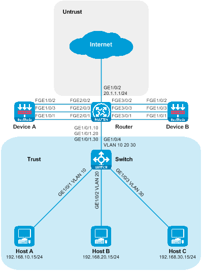
Figure 28 The network diagram of the side-mounted primary-backup deployment of SecBlade module, with Layer 3 stream diversion logic group.

|
Device |
Interface |
IP address |
Device |
Interface |
IP address |
|
Host A |
N/A |
192.168.10.15/24 |
Device A |
|
10.1.1.2/24 |
|
Host B |
N/A |
192.168.20.15/24 |
|
FGE1/0/2 |
10.1.2.2/24 |
|
Host C |
N/A |
192.168.30.15/24 |
|
|
1.1.1.1/30 |
|
Router |
GE1/0/1.10 |
192.168.10.1/24 |
Device B |
FGE1/0/1 |
10.1.1.3/24 |
|
|
GE1/0/1.20 |
192.168.20.1/24 |
|
FGE1/0/2 |
10.1.2.3/24 |
|
|
|
192.168.30.1/24 |
|
FGE1/0/3 |
1.1.1.2/30 |
|
|
GE1/0/2 |
20.1.1.1/24 |
|
|
|
|
|
Vlan-interface40 |
10.1.1.1/24 |
|
|
|
|
|
Vlan-interface50 |
10.1.2.1/24 |
|
|
|
Procedures
Configure the Switch
Create VLAN 10, VLAN 20, and VLAN 30. Then, add GigabitEthernet1/0/1, GigabitEthernet1/0/2, and GigabitEthernet1/0/3 to VLAN 10, VLAN 20, and VLAN 30 respectively.
<Switch> system-view
[Switch] vlan 10
[Switch-vlan10] port gigabitethernet 1/0/1
[Switch-vlan10] quit
[Switch] vlan 20
[Switch-vlan20] port gigabitethernet 1/0/2
[Switch-vlan20] quit
[Switch] vlan 30
[Switch-vlan30] port gigabitethernet 1/0/3
[Switch-vlan30] quit
Configure the link type of GigabitEthernet1/0/4 as Trunk, and allow the messages of VLAN 10, VLAN 20 and VLAN 30 to pass.
[Switch] interface gigabitethernet 1/0/4
[Switch-GigabitEthernet1/0/4] port link-type trunk
[Switch-GigabitEthernet1/0/4] port trunk permit vlan 10 20 30
[Switch-GigabitEthernet1/0/4] quit
Set up Router.
Configure the IP for the GigabitEthernet1/0/2 interface.
<Router> system-view
[Router] interface gigabitethernet 1/0/2
[Router-GigabitEthernet1/0/2] ip address 20.1.1.1 24
[Router-GigabitEthernet1/0/2] quit
Create Layer 3 subinterfaces GigabitEthernet1/0/1.10, GigabitEthernet1/0/1.20, and GigabitEthernet1/0/1.30, enable the Dot1q termination function, terminate VLAN 10, VLAN 20 and VLAN 30 respectively, and configure the interface IP.
[Router] interface gigabitethernet 1/0/1.10
[Router-GigabitEthernet1/0/1.10] vlan-type dot1q vid 10
[Router-GigabitEthernet1/0/1.10] ip address 192.168.10.1 24
[Router-GigabitEthernet1/0/1.10] quit
[Router] interface gigabitethernet 1/0/1.20
[Router-GigabitEthernet1/0/1.20] vlan-type dot1q vid 20
[Router-GigabitEthernet1/0/1.20] ip address 192.168.20.1 24
[Router-GigabitEthernet1/0/1.20] quit
[Router] interface gigabitethernet 1/0/1.30
[Router-GigabitEthernet1/0/1.30] vlan-type dot1q vid 30
[Router-GigabitEthernet1/0/1.30] ip address 192.168.30.1 24
[Router-GigabitEthernet1/0/1.30] quit
Switch the working mode of FortyGigE2/0/1, FortyGigE2/0/2, FortyGigE2/0/3, FortyGigE3/0/1, FortyGigE3/0/2 and FortyGigE3/0/3 to stratum 2 mode.
[Router] interface range fortygige 2/0/1 fortygige 2/0/2 fortygige 2/0/3 fortygige 3/0/1 fortygige 3/0/2 fortygige 3/0/3
[Router-if-range] port link-mode bridge
[Router-if-range] quit
Create VLAN 40, VLAN 50, and VLAN 1111. Add FortyGigE2/0/1 and FortyGigE3/0/1 to VLAN 40, add FortyGigE2/0/2 and FortyGigE3/0/2 to VLAN 50, and add FortyGigE2/0/3 and FortyGigE3/0/3 to VLAN 1111.
[Router] vlan 40
[Router-vlan40] port fortygige 2/0/1 fortygige 3/0/1
[Router-vlan40] quit
[Router] vlan 50
[Router-vlan50] port fortygige 2/0/2 fortygige 3/0/2
[Router-vlan50] quit
[Router] vlan 1111
[Router-vlan1111] port fortygige 2/0/3 fortygige 3/0/3
[Router-vlan1111] quit
Create VLAN 40 and VLAN 50 interfaces, and configure their IP addresses.
[Router] interface vlan-interface 40
[Router-Vlan-interface40] ip address 10.1.1.1 24
[Router-Vlan-interface40] quit
[Router] interface vlan-interface 50
[Router-Vlan-interface50] ip address 10.1.2.1 24
[Router-Vlan-interface50] quit
Turn off the fast forward load sharing function to prevent a layer three loop.
[Router] undo ip fast-forwarding load-sharing
Create an advanced IPv4 ACL to match the upstream and downstream traffic.
[Router] acl advanced 3001
[Router-acl-ipv4-adv-3001] rule permit ip source 192.168.10.0 0.0.0.255 destination 20.1.1.0 0.0.0.255
[Router-acl-ipv4-adv-3001] quit
[Router] acl advanced 3002
[Router-acl-ipv4-adv-3002] rule permit ip source 192.168.20.0 0.0.0.255 destination 20.1.1.0 0.0.0.255
[Router-acl-ipv4-adv-3002] quit
[Router] acl advanced 3003
[Router-acl-ipv4-adv-3003] rule permit ip source 192.168.30.0 0.0.0.255 destination 20.1.1.0 0.0.0.255
[Router-acl-ipv4-adv-3003] quit
[Router] acl advanced 3004
[Router-acl-ipv4-adv-3004] rule permit ip source 20.1.1.0 0.0.0.255 destination 192.168.10.0 0.0.0.255
[Router-acl-ipv4-adv-3004] rule permit ip source 20.1.1.0 0.0.0.255 destination 192.168.20.0 0.0.0.255
[Router-acl-ipv4-adv-3004] rule permit ip source 20.1.1.0 0.0.0.255 destination 192.168.30.0 0.0.0.255
[Router-acl-ipv4-adv-3004] quit
Configure policy routing and bind the policy routing to the interface.
[Router] policy-based-route vlan10out permit node 10
[Router-pbr-vlan10out-10] if-match acl 3001
[Router-pbr-vlan10out-10] apply next-hop 10.1.1.4
[Router-pbr-vlan10out-10] quit
[Router] policy-based-route vlan20out permit node 10
[Router-pbr-vlan20out-10] if-match acl 3002
[Router-pbr-vlan20out-10] apply next-hop 10.1.1.4
[Router-pbr-vlan20out-10] quit
[Router] policy-based-route vlan30out permit node 10
[Router-pbr-vlan30out-10] if-match acl 3003
[Router-pbr-vlan30out-10] apply next-hop 10.1.1.4
[Router-pbr-vlan30out-10] quit
[Router] policy-based-route internetin permit node 10
[Router-pbr-internetin-10] if-match acl 3004
[Router-pbr-internetin-10] apply next-hop 10.1.2.4
[Router-pbr-internetin-10] quit
[Router] interface gigabitethernet 1/0/1.10
[Router-GigabitEthernet1/0/1.10] ip policy-based-route vlan10out
[Router-GigabitEthernet1/0/1.10] quit
[Router] interface gigabitethernet 1/0/1.20
[Router-GigabitEthernet1/0/1.20] ip policy-based-route vlan20out
[Router-GigabitEthernet1/0/1.20] quit
[Router] interface gigabitethernet 1/0/1.30
[Router-GigabitEthernet1/0/1.30] ip policy-based-route vlan30out
[Router-GigabitEthernet1/0/1.30] quit
[Router] interface gigabitethernet 1/0/2
[Router-GigabitEthernet1/0/2] ip policy-based-route internetin
[Router-GigabitEthernet1/0/2] quit
Configure Device A
Configure the IP interfaces for FortyGigE1/0/1, FortyGigE1/0/2, and FortyGigE1/0/3. Also, set up VRRP backup groups 1 and 2 and associate them with HA.
<DeviceA> system-view
[DeviceA] interface fortygige 1/0/1
[DeviceA-FortyGigE1/0/1] ip address 10.1.1.2 24
[DeviceA-FortyGigE1/0/1] vrrp vrid 1 virtual-ip 10.1.1.4 active
[DeviceA-FortyGigE1/0/1] quit
[DeviceA] interface fortygige 1/0/2
[DeviceA-FortyGigE1/0/2] ip address 10.1.2.2 24
[DeviceA-FortyGigE1/0/2] vrrp vrid 2 virtual-ip 10.1.2.4 active
[DeviceA-FortyGigE1/0/2] quit
[DeviceA] interface fortygige 1/0/3
[DeviceA-FortyGigE1/0/3] ip address 1.1.1.1 30
[DeviceA-FortyGigE1/0/3] quit
Add FortyGigE1/0/1 and FortyGigE1/0/2 to the security domains Trust and Untrust, respectively.
[DeviceA] security-zone name trust
[DeviceA-security-zone-Trust] import interface fortygige 1/0/1
[DeviceA-security-zone-Trust] quit
[DeviceA] security-zone name untrust
[DeviceA-security-zone-Untrust] import interface fortygige 1/0/2
[DeviceA-security-zone-Untrust] quit
Configure the security policy to allow inter-domain messages to pass.
[DeviceA] security-policy ip
[DeviceA-security-policy-ip] rule name trust-untrust
[DeviceA-security-policy-ip-0-trust-untrust] action pass
[DeviceA-security-policy-ip-0-trust-untrust] source-zone trust
[DeviceA-security-policy-ip-0-trust-untrust] destination-zone untrust
[DeviceA-security-policy-ip-0-trust-untrust] quit
[DeviceA-security-policy-ip] rule name untrust-trust
[DeviceA-security-policy-ip-1-untrust-trust] action pass
[DeviceA-security-policy-ip-1-untrust-trust] source-zone untrust
[DeviceA-security-policy-ip-1-untrust-trust] destination-zone trust
[DeviceA-security-policy-ip-1-untrust-trust] quit
[DeviceA-security-policy-ip] quit
Guide for configuring static routes to direct inbound and outbound traffic forwarding.
[DeviceA] ip route-static 192.168.10.0 24 10.1.1.1
[DeviceA] ip route-static 192.168.20.0 24 10.1.1.1
[DeviceA] ip route-static 192.168.30.0 24 10.1.1.1
[DeviceA] ip route-static 20.1.1.0 24 10.1.2.1
Configure high availability (HA) RBM.
[DeviceA] remote-backup group
[DeviceA-remote-backup-group] remote-ip 1.1.1.2
[DeviceA-remote-backup-group] local-ip 1.1.1.1
[DeviceA-remote-backup-group] data-channel interface fortygige 1/0/3
[DeviceA-remote-backup-group] device-role primary
RBM_P[DeviceA-remote-backup-group] quit
Configure Device B
Configure the interface IP for FortyGigE1/0/1, FortyGigE1/0/2, and FortyGigE1/0/3. Set up VRRP backup groups 1 and 2 and associate them with HA.
<DeviceB> system-view
[DeviceB] interface fortygige 1/0/1
[DeviceB-FortyGigE1/0/1] ip address 10.1.1.3 24
[DeviceB-FortyGigE1/0/1] vrrp vrid 1 virtual-ip 10.1.1.4 standby
[DeviceB-FortyGigE1/0/1] quit
[DeviceB] interface fortygige 1/0/2
[DeviceB-FortyGigE1/0/2] ip address 10.1.2.3 24
[DeviceB-FortyGigE1/0/2] vrrp vrid 2 virtual-ip 10.1.2.4 standby
[DeviceB-FortyGigE1/0/2] quit
[DeviceB] interface fortygige 1/0/3
[DeviceB-FortyGigE1/0/3] ip address 1.1.1.2 30
[DeviceB-FortyGigE1/0/3] quit
Add FortyGigE1/0/1 and FortyGigE1/0/2 to the security domains Trust and Untrust, respectively.
[DeviceB] security-zone name trust
[DeviceB-security-zone-Trust] import interface fortygige 1/0/1
[DeviceB-security-zone-Trust] quit
[DeviceB] security-zone name untrust
[DeviceB-security-zone-Untrust] import interface fortygige 1/0/2
[DeviceB-security-zone-Untrust] quit
Configure the security policy to allow inter-domain messages to pass through.
[DeviceB] security-policy ip
[DeviceB-security-policy-ip] rule name trust-untrust
[DeviceB-security-policy-ip-0-trust-untrust] action pass
[DeviceB-security-policy-ip-0-trust-untrust] source-zone trust
[DeviceB-security-policy-ip-0-trust-untrust] destination-zone untrust
[DeviceB-security-policy-ip-0-trust-untrust] quit
[DeviceB-security-policy-ip] rule name untrust-trust
[DeviceB-security-policy-ip-1-untrust-trust] action pass
[DeviceB-security-policy-ip-1-untrust-trust] source-zone untrust
[DeviceB-security-policy-ip-1-untrust-trust] destination-zone trust
[DeviceB-security-policy-ip-1-untrust-trust] quit
[DeviceB-security-policy-ip] quit
Configure static routes to guide traffic forwarding for both upstream and downstream flow.
[DeviceB] ip route-static 192.168.10.0 24 10.1.1.1
[DeviceB] ip route-static 192.168.20.0 24 10.1.1.1
[DeviceB] ip route-static 192.168.30.0 24 10.1.1.1
[DeviceB] ip route-static 20.1.1.0 24 10.1.2.1
Configure the high availability (HA) RBM.
[DeviceB] remote-backup group
[DeviceB-remote-backup-group] remote-ip 1.1.1.1
[DeviceB-remote-backup-group] local-ip 1.1.1.2
[DeviceB-remote-backup-group] data-channel interface fortygige 1/0/3
[DeviceB-remote-backup-group] device-role secondary
RBM_S[DeviceB-remote-backup-group] quit
Verifying the configuration
To check if the HA configuration is effective and whether the HA channel is established, execute the following display command on Device A.
RBM_P[DeviceA] display remote-backup-group status
Remote backup group information:
Backup mode: Active/standby
Device management role: Primary
Device running status: Active
Data channel interface: FortyGigE1/0/3
Local IP: 1.1.1.1
Remote IP: 1.1.1.2 Destination port: 60064
Control channel status: Connected
Keepalive interval: 1s
Keepalive count: 10
Configuration consistency check interval: 12 hour
Configuration consistency check result: Not Performed
Configuration backup status: Auto sync enabled
Session backup status: Hot backup enabled
Uptime since last switchover: 0 days, 3 hours, 11 minutes
Switchover records:
Time Status change Cause
2021-06-22 13:33:33 Initial to Active Interface status changed
Executing the following display command on Device A allows you to view the state information of the VRRP backup group.
RBM_P[DeviceA] display vrrp
IPv4 Virtual Router Information:
Running mode : Standard
RBM control channel is established
VRRP active group status : Master
VRRP standby group status: Master
Total number of virtual routers : 2
Interface VRID State Running Adver Auth Virtual
Pri Timer Type IP
---------------------------------------------------------------------
FGE1/0/1 1 Master 100 100 None 10.1.1.4
FGE1/0/2 2 Master 100 100 None 10.1.2.4
Execute the following display command on Device B to check if the HA configuration has taken effect and if the HA channel has been established.
RBM_S[DeviceB] display remote-backup-group status
Remote backup group information:
Backup mode: Active/standby
Device management role: Secondary
Device running status: Standby
Data channel interface: FortyGigE1/0/3
Local IP: 1.1.1.2
Remote IP: 1.1.1.1 Destination port: 60064
Control channel status: Connected
Keepalive interval: 1s
Keepalive count: 10
Configuration consistency check interval: 12 hour
Configuration consistency check result: Not Performed
Configuration backup status: Auto sync enabled
Session backup status: Hot backup enabled
Uptime since last switchover: 0 days, 3 hours, 12 minutes
Switchover records:
Time Status change Cause
2022-06-22 13:34:34 Initial to Standby Interface status changed
To-view the state information of the VRRP backup group, execute the following display command on Device B.
RBM_S[DeviceB] display vrrp
IPv4 Virtual Router Information:
Running mode : Standard
RBM control channel is established
VRRP active group status : Backup
VRRP standby group status: Backup
Total number of virtual routers : 2
Interface VRID State Running Adver Auth Virtual
Pri Timer Type IP
---------------------------------------------------------------------
FGE1/0/1 1 Backup 100 100 None 10.1.1.4
FGE1/0/2 2 Backup 100 100 None 10.1.2.4
Host A is testing the connectivity to the Internet by using the ping test. It
can successfully ping the Internet address 20.1.1.1.
C:\>ping 20.1.1.1
Pinging 20.1.1.1 with 32 bytes of data:
Reply from 20.1.1.1: bytes=32 time=3ms TTL=254
Reply from 20.1.1.1: bytes=32 time=2ms TTL=254
Reply from 20.1.1.1: bytes=32 time=1ms TTL=254
Reply from 20.1.1.1: bytes=32 time=2ms TTL=254
Ping statistics for 20.1.1.1:
Packets: Sent = 4, Received = 4, Lost = 0 (0% loss),
Approximate round trip times in milli-seconds:
Minimum = 1ms, Maximum = 3ms, Average = 2ms
Host B is running a ping test on the Internet for connectivity. It can successfully ping the Internet address 20.1.1.1.
C:\>ping 20.1.1.1
Pinging 20.1.1.1 with 32 bytes of data:
Reply from 20.1.1.1: bytes=32 time=3ms TTL=254
Reply from 20.1.1.1: bytes=32 time=2ms TTL=254
Reply from 20.1.1.1: bytes=32 time=1ms TTL=254
Reply from 20.1.1.1: bytes=32 time=2ms TTL=254
Ping statistics for 20.1.1.1:
Packets: Sent = 4, Received = 4, Lost = 0 (0% loss),
Approximate round trip times in milli-seconds:
Minimum = 1ms, Maximum = 3ms, Average = 2ms
Host C conducts a ping test for internet connectivity and can successfully ping the internet address 20.1.1.1.
C:\>ping 20.1.1.1
Pinging 20.1.1.1 with 32 bytes of data:
Reply from 20.1.1.1: bytes=32 time=3ms TTL=254
Reply from 20.1.1.1: bytes=32 time=2ms TTL=254
Reply from 20.1.1.1: bytes=32 time=1ms TTL=254
Reply from 20.1.1.1: bytes=32 time=2ms TTL=254
Ping statistics for 20.1.1.1:
Packets: Sent = 4, Received = 4, Lost = 0 (0% loss),
Approximate round trip times in milli-seconds:
Minimum = 1ms, Maximum = 3ms, Average = 2ms
Check the session table on the Device, and there is a session table existing between the Host and 20.1.1.1.
RBM_P[DeviceA] display session table ipv4
Slot 1:
Initiator:
Source IP/port: 192.168.10.15/12005
Destination IP/port: 20.1.1.1/2048
DS-Lite tunnel peer: -
VPN instance/VLAN ID/Inline ID: -/-/-
Protocol: ICMP(1)
Inbound interface: FortyGigE1/0/1
Source security zone: Trust
Initiator:
Source IP/port: 192.168.20.15/12005
Destination IP/port: 20.1.1.1/2048
DS-Lite tunnel peer: -
VPN instance/VLAN ID/Inline ID: -/-/-
Protocol: ICMP(1)
Inbound interface: FortyGigE1/0/1
Source security zone: Trust
Initiator:
Source IP/port: 192.168.30.15/12005
Destination IP/port: 20.1.1.1/2048
DS-Lite tunnel peer: -
VPN instance/VLAN ID/Inline ID: -/-/-
Protocol: ICMP(1)
Inbound interface: FortyGigE1/0/1
Source security zone: Trust
Configuration file
Switch
#
vlan 10
#
vlan 20
#
vlan 30
#
interface GigabitEthernet1/0/1
port access vlan 10
#
interface GigabitEthernet1/0/2
port access vlan 20
#
interface GigabitEthernet1/0/3
port access vlan 30
#
interface GigabitEthernet1/0/4
port link-type trunk
port trunk permit vlan 10 20 30
#
Router
#
undo ip fast-forwarding load-sharing
#
vlan 40
#
vlan 50
#
vlan 1111
#
policy-based-route internetin permit node 10
if-match acl 3004
apply next-hop 10.1.2.4
#
policy-based-route vlan10out permit node 10
if-match acl 3001
apply next-hop 10.1.1.4
#
policy-based-route vlan20out permit node 10
if-match acl 3002
apply next-hop 10.1.1.4
#
policy-based-route vlan30out permit node 10
if-match acl 3003
apply next-hop 10.1.1.4
#
interface Vlan-interface40
ip address 10.1.1.1 255.255.255.0
#
interface Vlan-interface50
ip address 10.1.2.1 255.255.255.0
#
interface GigabitEthernet1/0/1.10
ip address 192.168.10.1 255.255.255.0
vlan-type dot1q vid 10
ip policy-based-route vlan10out
#
interface GigabitEthernet1/0/1.20
ip address 192.168.20.1 255.255.255.0
vlan-type dot1q vid 20
ip policy-based-route vlan20out
#
interface GigabitEthernet1/0/1.30
ip address 192.168.30.1 255.255.255.0
vlan-type dot1q vid 30
ip policy-based-route vlan30out
#
interface GigabitEthernet1/0/2
ip address 20.1.1.1 255.255.255.0
ip policy-based-route internetin
#
interface FortyGigE2/0/1
port link-mode bridge
port access vlan 40
#
interface FortyGigE2/0/2
port link-mode bridge
port access vlan 50
#
interface FortyGigE2/0/3
port link-mode bridge
port access vlan 1111
#
interface FortyGigE3/0/1
port link-mode bridge
port access vlan 40
#
interface FortyGigE3/0/2
port link-mode bridge
port access vlan 50
#
interface FortyGigE3/0/3
port link-mode bridge
port access vlan 1111
#
acl advanced 3001
rule 0 permit ip source 192.168.10.0 0.0.0.255 destination 20.1.1.0 0.0.0.255
#
acl advanced 3002
rule 0 permit ip source 192.168.20.0 0.0.0.255 destination 20.1.1.0 0.0.0.255
#
acl advanced 3003
rule 0 permit ip source 192.168.30.0 0.0.0.255 destination 20.1.1.0 0.0.0.255
#
acl advanced 3004
rule 0 permit ip source 20.1.1.0 0.0.0.255 destination 192.168.10.0 0.0.0.255
rule 5 permit ip source 20.1.1.0 0.0.0.255 destination 192.168.20.0 0.0.0.255
rule 10 permit ip source 20.1.1.0 0.0.0.255 destination 192.168.30.0 0.0.0.255
#
Device A
#
interface FortyGigE1/0/1
ip address 10.1.1.2 255.255.255.0
vrrp vrid 1 virtual-ip 10.1.1.4 active
#
interface FortyGigE1/0/2
ip address 10.1.2.2 255.255.255.0
vrrp vrid 2 virtual-ip 10.1.2.4 active
#
interface FortyGigE1/0/3
ip address 1.1.1.1 255.255.255.252
#
security-zone name Trust
import interface FortyGigE1/0/1
#
security-zone name Untrust
import interface FortyGigE1/0/2
#
ip route-static 20.1.1.0 24 10.1.2.1
ip route-static 192.168.10.0 24 10.1.1.1
ip route-static 192.168.20.0 24 10.1.1.1
ip route-static 192.168.30.0 24 10.1.1.1
#
security-policy ip
rule 0 name trust-untrust
action pass
source-zone trust
destination-zone untrust
rule 1 name untrust-trust
action pass
source-zone untrust
destination-zone trust
#
remote-backup group
data-channel interface FortyGigE1/0/3
local-ip 1.1.1.1
remote-ip 1.1.1.2
device-role primary
#
Device B
#
interface FortyGigE1/0/1
ip address 10.1.1.3 255.255.255.0
vrrp vrid 1 virtual-ip 10.1.1.4 standby
#
interface FortyGigE1/0/2
ip address 10.1.2.3 255.255.255.0
vrrp vrid 2 virtual-ip 10.1.2.4 standby
#
interface FortyGigE1/0/3
ip address 1.1.1.2 255.255.255.252
#
security-zone name Trust
import interface FortyGigE1/0/1
#
security-zone name Untrust
import interface FortyGigE1/0/2
#
ip route-static 20.1.1.0 24 10.1.2.1
ip route-static 192.168.10.0 24 10.1.1.1
ip route-static 192.168.20.0 24 10.1.1.1
ip route-static 192.168.30.0 24 10.1.1.1
#
security-policy ip
rule 0 name trust-untrust
action pass
source-zone trust
destination-zone untrust
rule 1 name untrust-trust
action pass
source-zone untrust
destination-zone trust
#
remote-backup group
data-channel interface FortyGigE1/0/3
local-ip 1.1.1.2
remote-ip 1.1.1.1
device-role secondary
#
Primary and backup deployment of the Layer 3 direct route involves the insertion of a SecBlade module (partitioning of VRF)
Network configuration
Host A, Host B, and Host C communicate with the Internet through access to Switch and Router. For security reasons, two SecBlade modules, Device A and Device B, need to be deployed on the Router for protective measures. The application requirements are as follows:
· The switch assigns Host A, Host B, and Host C to VLAN 10, VLAN 20, and VLAN 30 respectively. It allows traffic to transparently flow between the Host and the Internet.
· The Router interfaces with Host, Internet and Device at three levels. The downstream port and Vlan-interface40 are partitioned in the VPN host while the upstream port and Vlan-interface50 are assigned to the VPN internet. It forwards the traffic between Host and Internet by checking the static routing table.
· Device interfaces with Router at Layer 3, checking the static route table to forward traffic between Host and Internet, with Device A and Device B serving as primary and backup respectively.
Figure 29 Network diagram of layer three primary and backup deployment of SecBlade module (dividing VRF) grouping.
Figure 30 The logical networking diagram of SecBlade module deployment (dividing VRF) in the primary and secondary setup of Layer 3 straight path.
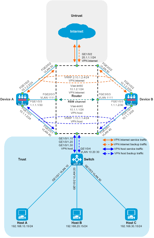
|
Device |
Interface |
IP address |
Device |
Interface |
IP Address |
|
Host A |
N/A |
192.168.10.15/24 |
Device A |
FGE1/0/1 |
10.1.1.2/30 |
|
Host B |
N/A |
192.168.20.15/24 |
|
FGE1/0/2 |
10.1.2.2/30 |
|
Host C |
N/A |
192.168.30.15/24 |
|
|
1.1.1.1/30 |
|
Router |
GE1/0/1.10 |
192.168.10.1/24 |
Device B |
|
10.1.1.3/30 |
|
|
GE1/0/1.20 |
192.168.20.1/24 |
|
FGE1/0/2 |
10.1.2.3/30 |
|
|
|
192.168.30.1/24 |
|
FGE1/0/3 |
1.1.1.2/30 |
|
|
Vlan-interface40 |
10.1.1.1/24 |
|
|
|
|
|
Vlan-interface50 |
10.1.2.1/24 |
|
|
|
|
|
GE1/0/2 |
20.1.1.1/24 |
|
|
|
Procedures
Configure the switch.
Create VLAN 10, VLAN 20, and VLAN 30, and add GigabitEthernet1/0/1, GigabitEthernet1/0/2, and GigabitEthernet1/0/3 to VLAN 10, VLAN 20, and VLAN 30 respectively.
<Switch> system-view
[Switch] vlan 10
[Switch-vlan10] port gigabitethernet 1/0/1
[Switch-vlan10] quit
[Switch] vlan 20
[Switch-vlan20] port gigabitethernet 1/0/2
[Switch-vlan20] quit
[Switch] vlan 30
[Switch-vlan30] port gigabitethernet 1/0/3
[Switch-vlan30] quit
Configure the link type of GigabitEthernet1/0/4 to Trunk, and allow messages from VLAN 10, VLAN 20, and VLAN 30 to pass.
[SwitchA] interface gigabitethernet 1/0/4
[SwitchA-GigabitEthernet1/0/4] port link-type trunk
[SwitchA-GigabitEthernet1/0/4] port trunk permit vlan 10 20 30
[SwitchA-GigabitEthernet1/0/4] quit
Configure Router
Set up the router
Create a VPN instance connecting host and internet.
<Router> system-view
[Router] ip vpn-instance host
[Router-vpn-instance-host] quit
[Router] ip vpn-instance internet
[Router-vpn-instance-internet] quit
Switch the working modes of the FortyGigE2/0/1, FortyGigE2/0/2, FortyGigE2/0/3, FortyGigE3/0/1, FortyGigE3/0/2, and FortyGigE3/0/3 interfaces to the Layer 2.
[Router] interface range fortygige 2/0/1 fortygige 2/0/2 fortygige 2/0/3 fortygige 3/0/1 fortygige 3/0/2 fortygige 3/0/3
[Router-if-range] port link-mode bridge
[Router-if-range] quit
Create VLAN 40, VLAN 50, and VLAN 1111. Add FortyGigE2/0/1 and FortyGigE3/0/1 to VLAN 40, include FortyGigE2/0/2 and FortyGigE3/0/2 to VLAN 50 and incorporate FortyGigE2/0/3 and FortyGigE3/0/3 into VLAN 1111.
[Router] vlan 40
[Router-vlan40] port fortygige 2/0/1 fortygige 3/0/1
[Router-vlan40] quit
[Router] vlan 50
[Router-vlan50] port fortygige 2/0/2 fortygige 3/0/2
[Router-vlan50] quit
[Router] vlan 1111
[Router-vlan1111] port fortygige 2/0/3 fortygige 3/0/3
[Router-vlan1111] quit
Create VLAN 40 and VLAN 50 interfaces, bind them to the VPN-instance, and configure the IP addresses for these VLAN interfaces.
[Router] interface vlan-interface 40
[Router-Vlan-interface40] ip binding vpn-instance host
[Router-Vlan-interface40] ip address 10.1.1.1 24
[Router-Vlan-interface40] quit
[Router] interface vlan-interface 50
[Router-Vlan-interface50] ip binding vpn-instance internet
[Router-Vlan-interface50] ip address 10.1.2.1 24
[Router-Vlan-interface50] quit
Create Layer 3 subinterfaces GigabitEthernet1/0/1.10, GigabitEthernet1/0/1.20, and GigabitEthernet1/0/1.30, enable the Dot1q termination function, individually terminate VLAN 10, VLAN 20, and VLAN 30, bind to the VPN instance, and configure the interface IP.
[Router] interface gigabitethernet 1/0/1.10
[Router-GigabitEthernet1/0/1.10] vlan-type dot1q vid 10
[Router-GigabitEthernet1/0/1.10] ip binding vpn-instance host
[Router-GigabitEthernet1/0/1.10] ip address 192.168.10.1 24
[Router-GigabitEthernet1/0/1.10] quit
[Router] interface gigabitethernet 1/0/1.20
[Router-GigabitEthernet1/0/1.20] vlan-type dot1q vid 20
[Router-GigabitEthernet1/0/1.20] ip binding vpn-instance host
[Router-GigabitEthernet1/0/1.20] ip address 192.168.20.1 24
[Router-GigabitEthernet1/0/1.20] quit
[Router] interface gigabitethernet 1/0/1.30
[Router-GigabitEthernet1/0/1.30] vlan-type dot1q vid 30
[Router-GigabitEthernet1/0/1.30] ip binding vpn-instance host
[Router-GigabitEthernet1/0/1.30] ip address 192.168.30.1 24
[Router-GigabitEthernet1/0/1.30] quit
Configure the IP of GigabitEthernet1/0/2 interface and bind it to the VPN-instance.
[Router] interface gigabitethernet 1/0/2
[Router-GigabitEthernet1/0/2] ip binding vpn-instance internet
[Router-GigabitEthernet1/0/2] ip address 20.1.1.1 24
[Router-GigabitEthernet1/0/2] quit
Configure the static route to guide upstream and downstream traffic forwarding.
[Router] ip route-static vpn-instance host 20.1.1.0 24 vpn-instance host 10.1.1.4
[Router] ip route-static vpn-instance internet 192.168.10.0 24 vpn-instance internet 10.1.2.4
[Router] ip route-static vpn-instance internet 192.168.20.0 24 vpn-instance internet 10.1.2.4
[Router] ip route-static vpn-instance internet 192.168.30.0 24 vpn-instance internet 10.1.2.4
Configure Device A
Configure the interface IPs for FortyGigE1/0/1, FortyGigE1/0/2, and FortyGigE1/0/3. Set up VRRP backup groups 1 and 2, and associate them with HA.
<DeviceA> system-view
[DeviceA] interface fortygige 1/0/1
[DeviceA-FortyGigE1/0/1] ip address 10.1.1.2 24
[DeviceA-FortyGigE1/0/1] vrrp vrid 1 virtual-ip 10.1.1.4 active
[DeviceA-FortyGigE1/0/1] quit
[DeviceA] interface fortygige 1/0/2
[DeviceA-FortyGigE1/0/2] ip address 10.1.2.2 24
[DeviceA-FortyGigE1/0/2] vrrp vrid 2 virtual-ip 10.1.2.4 active
[DeviceA-FortyGigE1/0/2] quit
[DeviceA] interface fortygige 1/0/3
[DeviceA-FortyGigE1/0/3] ip address 1.1.1.1 30
[DeviceA-FortyGigE1/0/3] quit
Add FortyGigE1/0/1 and FortyGigE1/0/2 to the security domains Trust and Untrust, respectively.
[DeviceA] security-zone name trust
[DeviceA-security-zone-Trust] import interface fortygige 1/0/1
[DeviceA-security-zone-Trust] quit
[DeviceA] security-zone name untrust
[DeviceA-security-zone-Untrust] import interface fortygige 1/0/2
[DeviceA-security-zone-Untrust] quit
The security policy is configured to allow inter-domain messages to pass.
[DeviceA] security-policy ip
[DeviceA-security-policy-ip] rule name trust-untrust
[DeviceA-security-policy-ip-0-trust-untrust] action pass
[DeviceA-security-policy-ip-0-trust-untrust] source-zone trust
[DeviceA-security-policy-ip-0-trust-untrust] destination-zone untrust
[DeviceA-security-policy-ip-0-trust-untrust] quit
[DeviceA-security-policy-ip] rule name untrust-trust
[DeviceA-security-policy-ip-1-untrust-trust] action pass
[DeviceA-security-policy-ip-1-untrust-trust] source-zone untrust
[DeviceA-security-policy-ip-1-untrust-trust] destination-zone trust
[DeviceA-security-policy-ip-1-untrust-trust] quit
[DeviceA-security-policy-ip] quit
Configure the static route to guide the traffic forwarding for upstream and downstream traffic.
[DeviceA] ip route-static 192.168.10.0 24 10.1.1.1
[DeviceA] ip route-static 192.168.20.0 24 10.1.1.1
[DeviceA] ip route-static 192.168.30.0 24 10.1.1.1
[DeviceA] ip route-static 20.1.1.0 24 10.1.2.1
Configure high availability (HA) RBM.
[DeviceA] remote-backup group
[DeviceA-remote-backup-group] remote-ip 1.1.1.2
[DeviceA-remote-backup-group] local-ip 1.1.1.1
[DeviceA-remote-backup-group] data-channel interface fortygige 1/0/3
[DeviceA-remote-backup-group] device-role primary
RBM_P[DeviceA-remote-backup-group] quit
Configure Device B
Configure the interface IP for FortyGigE1/0/1, FortyGigE1/0/2, and FortyGigE1/0/3. Set up VRRP backup groups 1 and 2, and associate them with HA.
<DeviceB> system-view
[DeviceB] interface fortygige 1/0/1
[DeviceB-FortyGigE1/0/1] ip address 10.1.1.3 24
[DeviceB-FortyGigE1/0/1] vrrp vrid 1 virtual-ip 10.1.1.4 standby
[DeviceB-FortyGigE1/0/1] quit
[DeviceB] interface fortygige 1/0/2
[DeviceB-FortyGigE1/0/2] ip address 10.1.2.3 24
[DeviceB-FortyGigE1/0/2] vrrp vrid 2 virtual-ip 10.1.2.4 standby
[DeviceB-FortyGigE1/0/2] quit
[DeviceB] interface fortygige 1/0/3
[DeviceB-FortyGigE1/0/3] ip address 1.1.1.2 30
[DeviceB-FortyGigE1/0/3] quit
Add FortyGigE1/0/1 and FortyGigE1/0/2 to the security domains, Trust and Untrust, respectively.
[DeviceB] security-zone name trust
[DeviceB-security-zone-Trust] import interface fortygige 1/0/1
[DeviceB-security-zone-Trust] quit
[DeviceB] security-zone name untrust
[DeviceB-security-zone-Untrust] import interface fortygige 1/0/2
[DeviceB-security-zone-Untrust] quit
Configure the security policy to allow inter-domain messages to pass.
[DeviceB] security-policy ip
[DeviceB-security-policy-ip] rule name trust-untrust
[DeviceB-security-policy-ip-0-trust-untrust] action pass
[DeviceB-security-policy-ip-0-trust-untrust] source-zone trust
[DeviceB-security-policy-ip-0-trust-untrust] destination-zone untrust
[DeviceB-security-policy-ip-0-trust-untrust] quit
[DeviceB-security-policy-ip] rule name untrust-trust
[DeviceB-security-policy-ip-1-untrust-trust] action pass
[DeviceB-security-policy-ip-1-untrust-trust] source-zone untrust
[DeviceB-security-policy-ip-1-untrust-trust] destination-zone trust
[DeviceB-security-policy-ip-1-untrust-trust] quit
[DeviceB-security-policy-ip] quit
The guide to configuring the static route directs the traffic forwarding for both upstream and downstream.
[DeviceB] ip route-static 192.168.10.0 24 10.1.1.1
[DeviceB] ip route-static 192.168.20.0 24 10.1.1.1
[DeviceB] ip route-static 192.168.30.0 24 10.1.1.1
[DeviceB] ip route-static 20.1.1.0 24 10.1.2.1
Configure high availability (HA) RBM.
[DeviceB] remote-backup group
[DeviceB-remote-backup-group] remote-ip 1.1.1.1
[DeviceB-remote-backup-group] local-ip 1.1.1.2
[DeviceB-remote-backup-group] data-channel interface fortygige 1/0/3
[DeviceB-remote-backup-group] device-role secondary
RBM_S[DeviceB-remote-backup-group] quit
Verifying the configuration
To examine if the HA configuration is active and if the HA channel has been established, execute the following display command on Device A.
RBM_P[DeviceA] display remote-backup-group status
Remote backup group information:
Backup mode: Active/standby
Device management role: Primary
Device running status: Active
Data channel interface: FortyGigE1/0/3
Local IP: 1.1.1.1
Remote IP: 1.1.1.2 Destination port: 60064
Control channel status: Connected
Keepalive interval: 1s
Keepalive count: 10
Configuration consistency check interval: 12 hour
Configuration consistency check result: Not Performed
Configuration backup status: Auto sync enabled
Session backup status: Hot backup enabled
Uptime since last switchover: 0 days, 3 hours, 11 minutes
Switchover records:
Time Status change Cause
2021-06-22 13:33:33 Initial to Active Interface status changed
To view the state information of the VRRP backup group, execute the following display command on Device A.
RBM_P[DeviceA] display vrrp
IPv4 Virtual Router Information:
Running mode : Standard
RBM control channel is established
VRRP active group status : Master
VRRP standby group status: Master
Total number of virtual routers : 2
Interface VRID State Running Adver Auth Virtual
Pri Timer Type IP
---------------------------------------------------------------------
FGE1/0/1 1 Master 100 100 None 10.1.1.4
FGE1/0/2 2 Master 100 100 None 10.1.2.4
To check if the HA configuration is effective and if the HA channel is established, execute the following display command on Device B.
RBM_S[DeviceB] display remote-backup-group status
Remote backup group information:
Backup mode: Active/standby
Device management role: Secondary
Device running status: Standby
Data channel interface: FortyGigE1/0/3
Local IP: 1.1.1.2
Remote IP: 1.1.1.1 Destination port: 60064
Control channel status: Connected
Keepalive interval: 1s
Keepalive count: 10
Configuration consistency check interval: 12 hour
Configuration consistency check result: Not Performed
Configuration backup status: Auto sync enabled
Session backup status: Hot backup enabled
Uptime since last switchover: 0 days, 3 hours, 12 minutes
Switchover records:
Time Status change Cause
2022-06-22 13:34:34 Initial to Standby Interface status changed
To view the status information of the VRRP backup group on Device B, execute the following display command.
RBM_S[DeviceB] display vrrp
IPv4 Virtual Router Information:
Running mode : Standard
RBM control channel is established
VRRP active group status : Backup
VRRP standby group status: Backup
Total number of virtual routers : 2
Interface VRID State Running Adver Auth Virtual
Pri Timer Type IP
---------------------------------------------------------------------
FGE1/0/1 1 Backup 100 100 None 10.1.1.4
FGE1/0/2 2 Backup 100 100 None 10.1.2.4
Host A conducts a ping test on the
connectivity to the Internet, successfully pinging the Internet address
20.1.1.1.
C:\>ping 20.1.1.1
Pinging 20.1.1.1 with 32 bytes of data:
Reply from 20.1.1.1: bytes=32 time=3ms TTL=254
Reply from 20.1.1.1: bytes=32 time=2ms TTL=254
Reply from 20.1.1.1: bytes=32 time=1ms TTL=254
Reply from 20.1.1.1: bytes=32 time=2ms TTL=254
Ping statistics for 20.1.1.1:
Packets: Sent = 4, Received = 4, Lost = 0 (0% loss),
Approximate round trip times in milli-seconds:
Minimum = 1ms, Maximum = 3ms, Average = 2ms
Host B conducts a ping test to check the connectivity to the Internet and can successfully ping the Internet address 20.1.1.1.
C:\>ping 20.1.1.1
Pinging 20.1.1.1 with 32 bytes of data:
Reply from 20.1.1.1: bytes=32 time=3ms TTL=254
Reply from 20.1.1.1: bytes=32 time=2ms TTL=254
Reply from 20.1.1.1: bytes=32 time=1ms TTL=254
Reply from 20.1.1.1: bytes=32 time=2ms TTL=254
Ping statistics for 20.1.1.1:
Packets: Sent = 4, Received = 4, Lost = 0 (0% loss),
Approximate round trip times in milli-seconds:
Minimum = 1ms, Maximum = 3ms, Average = 2ms
# On Host C, test the internet connectivity by pinging. The Internet address 20.1.1.1 is reachable.
C:\>ping 20.1.1.1
Pinging 20.1.1.1 with 32 bytes of data:
Reply from 20.1.1.1: bytes=32 time=3ms TTL=254
Reply from 20.1.1.1: bytes=32 time=2ms TTL=254
Reply from 20.1.1.1: bytes=32 time=1ms TTL=254
Reply from 20.1.1.1: bytes=32 time=2ms TTL=254
Ping statistics for 20.1.1.1:
Packets: Sent = 4, Received = 4, Lost = 0 (0% loss),
Approximate round trip times in milli-seconds:
Minimum = 1ms, Maximum = 3ms, Average = 2ms
Check the session table on the device, there is a session table between the Host and 20.1.1.1.
RBM_P[DeviceA] display session table ipv4
Slot 1:
Initiator:
Source IP/port: 192.168.10.15/12005
Destination IP/port: 20.1.1.1/2048
DS-Lite tunnel peer: -
VPN instance/VLAN ID/Inline ID: -/-/-
Protocol: ICMP(1)
Inbound interface: FortyGigE1/0/1
Source security zone: Trust
Initiator:
Source IP/port: 192.168.20.15/12005
Destination IP/port: 20.1.1.1/2048
DS-Lite tunnel peer: -
VPN instance/VLAN ID/Inline ID: -/-/-
Protocol: ICMP(1)
Inbound interface: FortyGigE1/0/1
Source security zone: Trust
Initiator:
Source IP/port: 192.168.30.15/12005
Destination IP/port: 20.1.1.1/2048
DS-Lite tunnel peer: -
VPN instance/VLAN ID/Inline ID: -/-/-
Protocol: ICMP(1)
Inbound interface: FortyGigE1/0/1
Source security zone: Trust
Configuration file
Switch
#
vlan 10
#
vlan 20
#
vlan 30
#
interface GigabitEthernet1/0/1
port access vlan 10
#
interface GigabitEthernet1/0/2
port access vlan 20
#
interface GigabitEthernet1/0/3
port access vlan 30
#
interface GigabitEthernet1/0/4
port link-type trunk
port trunk permit vlan 10 20 30
#
Router
#
ip vpn-instance host
#
ip vpn-instance internet
#
vlan 40
#
vlan 50
#
vlan 1111
#
interface Vlan-interface40
ip binding vpn-instance host
ip address 10.1.1.1 255.255.255.0
#
interface Vlan-interface50
ip binding vpn-instance internet
ip address 10.1.2.1 255.255.255.0
#
interface GigabitEthernet1/0/1.10
ip binding vpn-instance host
ip address 192.168.10.1 255.255.255.0
vlan-type dot1q vid 10
#
interface GigabitEthernet1/0/1.20
ip binding vpn-instance host
ip address 192.168.20.1 255.255.255.0
vlan-type dot1q vid 20
#
interface GigabitEthernet1/0/1.30
ip binding vpn-instance host
ip address 192.168.30.1 255.255.255.0
vlan-type dot1q vid 30
#
interface GigabitEthernet1/0/2
ip binding vpn-instance internet
ip address 20.1.1.1 255.255.255.0
#
interface FortyGige2/0/1
port link-mode bridge
port access vlan 40
#
interface FortyGige2/0/2
port link-mode bridge
port access vlan 50
#
interface FortyGige2/0/3
port link-mode bridge
port access vlan 1111
#
interface FortyGige3/0/1
port link-mode bridge
port access vlan 40
#
interface FortyGige3/0/2
port link-mode bridge
port access vlan 50
#
interface FortyGige3/0/3
port link-mode bridge
port access vlan 1111
#
ip route-static vpn-instance host 20.1.1.0 24 10.1.1.4
ip route-static vpn-instance internet 192.168.10.0 24 10.1.2.4
ip route-static vpn-instance internet 192.168.20.0 24 10.1.2.4
ip route-static vpn-instance internet 192.168.30.0 24 10.1.2.4
#
Device A
#
interface FortyGigE1/0/1
ip address 10.1.1.2 255.255.255.0
vrrp vrid 1 virtual-ip 10.1.1.4 active
#
interface FortyGigE1/0/2
ip address 10.1.2.2 255.255.255.0
vrrp vrid 2 virtual-ip 10.1.2.4 active
#
interface FortyGigE1/0/3
ip address 1.1.1.1 255.255.255.252
#
security-zone name Trust
import interface FortyGigE1/0/1
#
security-zone name Untrust
import interface FortyGigE1/0/2
#
ip route-static 20.1.1.0 24 10.1.2.1
ip route-static 192.168.10.0 24 10.1.1.1
ip route-static 192.168.20.0 24 10.1.1.1
ip route-static 192.168.30.0 24 10.1.1.1
#
security-policy ip
rule 0 name trust-untrust
action pass
source-zone trust
destination-zone untrust
rule 1 name untrust-trust
action pass
source-zone untrust
destination-zone trust
#
remote-backup group
data-channel interface FortyGigE1/0/3
local-ip 1.1.1.1
remote-ip 1.1.1.2
device-role primary
#
Device B
#
interface FortyGigE1/0/1
ip address 10.1.1.3 255.255.255.0
vrrp vrid 1 virtual-ip 10.1.1.4 standby
#
interface FortyGigE1/0/2
ip address 10.1.2.3 255.255.255.0
vrrp vrid 2 virtual-ip 10.1.2.4 standby
#
interface FortyGigE1/0/3
ip address 1.1.1.2 255.255.255.252
#
security-zone name Trust
import interface FortyGigE1/0/1
#
security-zone name Untrust
import interface FortyGigE1/0/2
#
ip route-static 20.1.1.0 24 10.1.2.1
ip route-static 192.168.10.0 24 10.1.1.1
ip route-static 192.168.20.0 24 10.1.1.1
ip route-static 192.168.30.0 24 10.1.1.1
#
security-policy ip
rule 0 name trust-untrust
action pass
source-zone trust
destination-zone untrust
rule 1 name untrust-trust
action pass
source-zone untrust
destination-zone trust
#
remote-backup group
data-channel interface FortyGigE1/0/3
local-ip 1.1.1.2
remote-ip 1.1.1.1
device-role secondary
#
SecBlade module deployment in a main/backup mode on Layer 3 direct route with VLANs
Network configuration
Host A, Host B, and Host C communicate with the Internet via access switch Switch A, aggregation switch Switch B, and core switch Switch C. For security reasons, two SecBlade modules, Device A and Device B, need to be deployed on the aggregation switch Switch B to provide security protection. The application requirements are as follows:
· Switch A assigns Host A, Host B, and Host C to VLAN 10, VLAN 20, and VLAN 30 respectively, acting as their gateway. It checks the static route table to forward traffic from these hosts to the Internet.
· Switch B assigns the downstream service port to VLAN 40 and the upstream service port to VLAN 50. The interconnection ports with the Device are separately allocated to VLAN 40 and VLAN 50, enabling traffic between the Host and the Internet to be transparently transmitted upstream and downstream to the Device.
· The device interfaces on Layer 3 with Switch A and Switch C, checking the static route table to traffic forwarding between the Host and the Internet. Device A and Device B are used for primary and secondary backups.
· Switch C interfaces with Device at Layer 3, checks the static routing table, and forwards the Internet traffic to the Host.
Figure 31 Network diagram of SecBlade module deployment (dividing VLAN) in the main and backup of the Layer 3 direct road group.
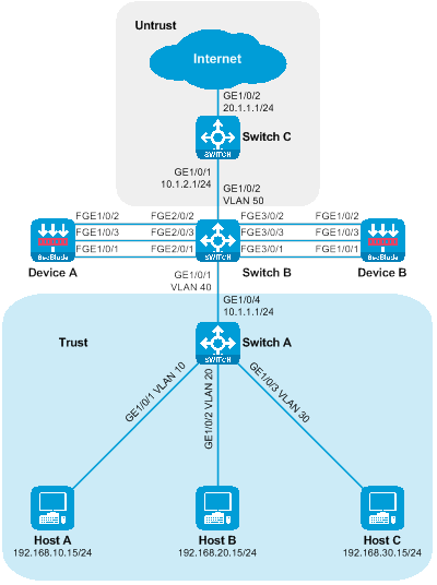
Figure 32 The logical network diagram of the SecBlade module deployment in the main and backup of the Layer 3 direct route (dividing VLAN).
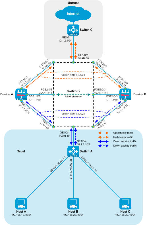
|
Device |
Interface |
IP address |
Device |
Interface |
IP address |
|
Host A |
N/A |
192.168.10.15/24 |
Device B |
FGE1/0/1 |
10.1.1.3/24 |
|
Host B |
N/A |
192.168.20.15/24 |
|
|
10.1.2.3/24 |
|
Host C |
N/A |
192.168.30.15/24 |
|
FGE1/0/3 |
1.1.1.2/30 |
|
Switch A |
"GE1/0/4" |
10.1.1.1/24 |
Switch C |
|
10.1.2.1/24 |
|
|
Vlan-interface 10 |
192.168.10.1/24 |
|
|
20.1.1.1/24 |
|
|
Vlan-interface 20 |
192.168.20.1/24 |
|
|
|
|
|
VLAN Interface 30 |
192.168.30.1/24 |
|
|
|
|
Device A |
FGE1/0/1 |
10.1.1.2/24 |
|
|
|
|
|
FGE1/0/2 |
10.1.2.2/24 |
|
|
|
|
|
|
1.1.1.1/30 |
|
|
|
Procedures
Configuring Switch A
Create VLAN 10, VLAN 20, and VLAN 30, then add GigabitEthernet1/0/1, GigabitEthernet1/0/2, and GigabitEthernet1/0/3 to VLAN 10, VLAN 20, and VLAN 30, respectively.
<SwitchA> system-view
[SwitchA] vlan 10
[SwitchA-vlan10] port gigabitethernet 1/0/1
[SwitchA-vlan10] quit
[SwitchA] vlan 20
[SwitchA-vlan20] port gigabitethernet 1/0/2
[SwitchA-vlan20] quit
[SwitchA] vlan 30
[SwitchA-vlan30] port gigabitethernet 1/0/3
[SwitchA-vlan30] quit
Create interfaces for VLAN 10, VLAN 20 and VLAN 30, and configure their IP addresses.
[SwitchA] interface vlan-interface 10
[SwitchA-Vlan-interface10] ip address 192.168.10.1 24
[SwitchA-Vlan-interface10] quit
[SwitchA] interface vlan-interface 20
[SwitchA-Vlan-interface20] ip address 192.168.20.1 24
[SwitchA-Vlan-interface20] quit
[SwitchA] interface vlan-interface 30
[SwitchA-Vlan-interface30] ip address 192.168.30.1 24
[SwitchA-Vlan-interface30] quit
Switch the operation mode of GigabitEthernet1/0/4 to layer 3 mode and configure the IP address.
[SwitchA] interface gigabitethernet 1/0/4
[SwitchA-GigabitEthernet1/0/4] port link-mode route
The configuration of the interface will be restored to the default. Continue? [Y] :y
[SwitchA-GigabitEthernet1/0/4] ip address 10.1.1.1 24
[SwitchA-GigabitEthernet1/0/4] quit
Configure the static route to guide the upstream traffic forwarding.
[SwitchA] ip route-static 20.1.1.0 24 10.1.1.4
Configuring Switch B
Create VLAN 40, VLAN 50, and VLAN 1111. Add GigabitEthernet1/0/1, FortyGigE2/0/1, and FortyGigE3/0/1 to VLAN 40. Add GigabitEthernet1/0/2, FortyGigE2/0/2, and FortyGigE3/0/2 to VLAN 50. Lastly, add FortyGigE2/0/3 and FortyGigE3/0/3 to VLAN 1111.
<SwitchB> system-view
[SwitchB] vlan 40
[SwitchB-vlan40] port GigabitEthernet 1/0/1 fortygige 2/0/1 fortygige 3/0/1
[SwitchB-vlan40] quit
[SwitchB] vlan 50
[SwitchB-vlan50] port GigabitEthernet 1/0/2 fortygige 2/0/2 fortygige 3/0/2
[SwitchB-vlan50] quit
[SwitchB] vlan 1111
[SwitchB-vlan1111] port fortygige 2/0/3 fortygige 3/0/3
[SwitchB-vlan1111] quit
Configuring Switch C
Switch the working mode of GigabitEthernet1/0/1 to layer 3 mode and configure its IP address.
<SwitchC> system-view
[SwitchC] interface gigabitethernet 1/0/1
[SwitchC-GigabitEthernet1/0/1] port link-mode route
The configuration of the interface will be restored to the default. Continue? [Y] :y
[SwitchC-GigabitEthernet1/0/1] ip address 10.1.2.1 24
[SwitchC-GigabitEthernet1/0/1] quit
Switch the operating mode of GigabitEthernet1/0/2 to layer 3 mode and configure the IP address.
[SwitchC] interface gigabitethernet 1/0/2
[SwitchC-GigabitEthernet1/0/2] port link-mode route
The configuration of the interface will be restored to the default. Continue? [Y] :y
[SwitchC-GigabitEthernet1/0/2] ip address 20.1.1.1 24
[SwitchC-GigabitEthernet1/0/2] quit
The guide is on configuring the static route to direct the downstream traffic forwarding.
[SwitchC] ip route-static 192.168.10.0 24 10.1.2.4
[SwitchC] ip route-static 192.168.20.0 24 10.1.2.4
[SwitchC] ip route-static 192.168.30.0 24 10.1.2.4
Configure Device A
Configure the interface IP for FortyGigE1/0/1, FortyGigE1/0/2, and FortyGigE1/0/3. Set up VRRP backup groups 1 and 2, and associate them with HA.
<DeviceA> system-view
[DeviceA] interface fortygige 1/0/1
[DeviceA-FortyGigE1/0/1] ip address 10.1.1.2 24
[DeviceA-FortyGigE1/0/1] vrrp vrid 1 virtual-ip 10.1.1.4 active
[DeviceA-FortyGigE1/0/1] quit
[DeviceA] interface fortygige 1/0/2
[DeviceA-FortyGigE1/0/2] ip address 10.1.2.2 24
[DeviceA-FortyGigE1/0/2] vrrp vrid 2 virtual-ip 10.1.2.4 active
[DeviceA-FortyGigE1/0/2] quit
[DeviceA] interface fortygige 1/0/3
[DeviceA-FortyGigE1/0/3] ip address 1.1.1.1 30
[DeviceA-FortyGigE1/0/3] quit
Add FortyGigE1/0/1 and FortyGigE1/0/2 to the security zones Trust and Untrust, respectively.
[DeviceA] security-zone name trust
[DeviceA-security-zone-Trust] import interface fortygige 1/0/1
[DeviceA-security-zone-Trust] quit
[DeviceA] security-zone name untrust
[DeviceA-security-zone-Untrust] import interface fortygige 1/0/2
[DeviceA-security-zone-Untrust] quit
Configure the security policy to allow inter-domain messages to pass.
[DeviceA] security-policy ip
[DeviceA-security-policy-ip] rule name trust-untrust
[DeviceA-security-policy-ip-0-trust-untrust] action pass
[DeviceA-security-policy-ip-0-trust-untrust] source-zone trust
[DeviceA-security-policy-ip-0-trust-untrust] destination-zone untrust
[DeviceA-security-policy-ip-0-trust-untrust] quit
[DeviceA-security-policy-ip] rule name untrust-trust
[DeviceA-security-policy-ip-1-untrust-trust] action pass
[DeviceA-security-policy-ip-1-untrust-trust] source-zone untrust
[DeviceA-security-policy-ip-1-untrust-trust] destination-zone trust
[DeviceA-security-policy-ip-1-untrust-trust] quit
[DeviceA-security-policy-ip] quit
Configure static routes to guide the traffic forwarding for both upstream and downstream flows.
[DeviceA] ip route-static 192.168.10.0 24 10.1.1.1
[DeviceA] ip route-static 192.168.20.0 24 10.1.1.1
[DeviceA] ip route-static 192.168.30.0 24 10.1.1.1
[DeviceA] ip route-static 20.1.1.0 24 10.1.2.1
Configure the high availability (HA) RBM.
[DeviceA] remote-backup group
[DeviceA-remote-backup-group] remote-ip 1.1.1.2
[DeviceA-remote-backup-group] local-ip 1.1.1.1
[DeviceA-remote-backup-group] data-channel interface fortygige 1/0/3
[DeviceA-remote-backup-group] device-role primary
RBM_P[DeviceA-remote-backup-group] quit
Configure Device B
Configure the IP interfaces of FortyGigE1/0/1, FortyGigE1/0/2, and FortyGigE1/0/3. Set up VRRP backup groups 1 and 2 and associate them with HA.
<DeviceB> system-view
[DeviceB] interface fortygige 1/0/1
[DeviceB-FortyGigE1/0/1] ip address 10.1.1.3 24
[DeviceB-FortyGigE1/0/1] vrrp vrid 1 virtual-ip 10.1.1.4 standby
[DeviceB-FortyGigE1/0/1] quit
[DeviceB] interface fortygige 1/0/2
[DeviceB-FortyGigE1/0/2] ip address 10.1.2.3 24
[DeviceB-FortyGigE1/0/2] vrrp vrid 2 virtual-ip 10.1.2.4 standby
[DeviceB-FortyGigE1/0/2] quit
[DeviceB] interface fortygige 1/0/3
[DeviceB-FortyGigE1/0/3] ip address 1.1.1.2 30
[DeviceB-FortyGigE1/0/3] quit
Add FortyGigE1/0/1 and FortyGigE1/0/2 into the security domains Trust and Untrust respectively.
[DeviceB] security-zone name trust
[DeviceB-security-zone-Trust] import interface fortygige 1/0/1
[DeviceB-security-zone-Trust] quit
[DeviceB] security-zone name untrust
[DeviceB-security-zone-Untrust] import interface fortygige 1/0/2
[DeviceB-security-zone-Untrust] quit
Configure the security policy to allow inter-domain messages to pass.
[DeviceB] security-policy ip
[DeviceB-security-policy-ip] rule name trust-untrust
[DeviceB-security-policy-ip-0-trust-untrust] action pass
[DeviceB-security-policy-ip-0-trust-untrust] source-zone trust
[DeviceB-security-policy-ip-0-trust-untrust] destination-zone untrust
[DeviceB-security-policy-ip-0-trust-untrust] quit
[DeviceB-security-policy-ip] rule name untrust-trust
[DeviceB-security-policy-ip-1-untrust-trust] action pass
[DeviceB-security-policy-ip-1-untrust-trust] source-zone untrust
[DeviceB-security-policy-ip-1-untrust-trust] destination-zone trust
[DeviceB-security-policy-ip-1-untrust-trust] quit
[DeviceB-security-policy-ip] quit
Configure static routes to guide traffic forwarding for both upstream and downstream flows.
[DeviceB] ip route-static 192.168.10.0 24 10.1.1.1
[DeviceB] ip route-static 192.168.20.0 24 10.1.1.1
[DeviceB] ip route-static 192.168.30.0 24 10.1.1.1
[DeviceB] ip route-static 20.1.1.0 24 10.1.2.1
Configure high availability (HA) RBM.
[DeviceB] remote-backup group
[DeviceB-remote-backup-group] remote-ip 1.1.1.1
[DeviceB-remote-backup-group] local-ip 1.1.1.2
[DeviceB-remote-backup-group] data-channel interface fortygige 1/0/3
[DeviceB-remote-backup-group] device-role secondary
RBM_S[DeviceB-remote-backup-group] quit
Verifying the configuration
To check if the HA configuration is effective and whether the HA channel has been established on Device A, execute the following display command.
RBM_P[DeviceA] display remote-backup-group status
Remote backup group information:
Backup mode: Active/standby
Device management role: Primary
Device running status: Active
Data channel interface: FortyGigE1/0/3
Local IP: 1.1.1.1
Remote IP: 1.1.1.2 Destination port: 60064
Control channel status: Connected
Keepalive interval: 1s
Keepalive count: 10
Configuration consistency check interval: 12 hour
Configuration consistency check result: Not Performed
Configuration backup status: Auto sync enabled
Session backup status: Hot backup enabled
Uptime since last switchover: 0 days, 3 hours, 11 minutes
Switchover records:
Time Status change Cause
2021-06-22 13:33:33 Initial to Active Interface status changed
On Device A, execute the following display command to view the state information of the VRRP backup group.
RBM_P[DeviceA] display vrrp
IPv4 Virtual Router Information:
Running mode : Standard
RBM control channel is established
VRRP active group status : Master
VRRP standby group status: Master
Total number of virtual routers : 2
Interface VRID State Running Adver Auth Virtual
Pri Timer Type IP
---------------------------------------------------------------------
FGE1/0/1 1 Master 100 100 None 10.1.1.4
FGE1/0/2 2 Master 100 100 None 10.1.2.4
To see if the HA configuration has taken effect and if the HA channel has been set up, execute the following display command on Device B.
RBM_S[DeviceB] display remote-backup-group status
Remote backup group information:
Backup mode: Active/standby
Device management role: Secondary
Device running status: Standby
Data channel interface: FortyGigE1/0/3
Local IP: 1.1.1.2
Remote IP: 1.1.1.1 Destination port: 60064
Control channel status: Connected
Keepalive interval: 1s
Keepalive count: 10
Configuration consistency check interval: 12 hour
Configuration consistency check result: Not Performed
Configuration backup status: Auto sync enabled
Session backup status: Hot backup enabled
Uptime since last switchover: 0 days, 3 hours, 12 minutes
Switchover records:
Time Status change Cause
2022-06-22 13:34:34 Initial to Standby Interface status changed
To view the state information of the VRRP backup group, execute the following display command on Device B.
RBM_S[DeviceB] display vrrp
IPv4 Virtual Router Information:
Running mode : Standard
RBM control channel is established
VRRP active group status : Backup
VRRP standby group status: Backup
Total number of virtual routers : 2
Interface VRID State Running Adver Auth Virtual
Pri Timer Type IP
---------------------------------------------------------------------
FGE1/0/1 1 Backup 100 100 None 10.1.1.4
FGE1/0/2 2 Backup 100 100 None 10.1.2.4
Host A is conducting a ping test for Internet connectivity, and it can successfully ping the Internet address 20.1.1.1.
C:\>ping 20.1.1.1
Pinging 20.1.1.1 with 32 bytes of data:
Reply from 20.1.1.1: bytes=32 time=3ms TTL=254
Reply from 20.1.1.1: bytes=32 time=2ms TTL=254
Reply from 20.1.1.1: bytes=32 time=1ms TTL=254
Reply from 20.1.1.1: bytes=32 time=2ms TTL=254
Ping statistics for 20.1.1.1:
Packets: Sent = 4, Received = 4, Lost = 0 (0% loss),
Approximate round trip times in milli-seconds:
Minimum = 1ms, Maximum = 3ms, Average = 2ms
Host B conducts a connectivity test to the Internet using ping, and it can connect to the Internet address 20.1.1.1 successfully.
C:\>ping 20.1.1.1
Pinging 20.1.1.1 with 32 bytes of data:
Reply from 20.1.1.1: bytes=32 time=3ms TTL=254
Reply from 20.1.1.1: bytes=32 time=2ms TTL=254
Reply from 20.1.1.1: bytes=32 time=1ms TTL=254
Reply from 20.1.1.1: bytes=32 time=2ms TTL=254
Ping statistics for 20.1.1.1:
Packets: Sent = 4, Received = 4, Lost = 0 (0% loss),
Approximate round trip times in milli-seconds:
Minimum = 1ms, Maximum = 3ms, Average = 2ms
# On Host C, the connectivity to the Internet is being tested with ping. It successfully pings the Internet address 20.1.1.1.
C:\>ping 20.1.1.1
Pinging 20.1.1.1 with 32 bytes of data:
Reply from 20.1.1.1: bytes=32 time=3ms TTL=254
Reply from 20.1.1.1: bytes=32 time=2ms TTL=254
Reply from 20.1.1.1: bytes=32 time=1ms TTL=254
Reply from 20.1.1.1: bytes=32 time=2ms TTL=254
Ping statistics for 20.1.1.1:
Packets: Sent = 4, Received = 4, Lost = 0 (0% loss),
Approximate round trip times in milli-seconds:
Minimum = 1ms, Maximum = 3ms, Average = 2ms
Check the session table on the Device, there is a session table between the Host and 20.1.1.1.
RBM_P[DeviceA] display session table ipv4
Slot 1:
Initiator:
Source IP/port: 192.168.10.15/12005
Destination IP/port: 20.1.1.1/2048
DS-Lite tunnel peer: -
VPN instance/VLAN ID/Inline ID: -/-/-
Protocol: ICMP(1)
Inbound interface: FortyGigE1/0/1
Source security zone: Trust
Initiator:
Source IP/port: 192.168.20.15/12005
Destination IP/port: 20.1.1.1/2048
DS-Lite tunnel peer: -
VPN instance/VLAN ID/Inline ID: -/-/-
Protocol: ICMP(1)
Inbound interface: FortyGigE1/0/1
Source security zone: Trust
Initiator:
Source IP/port: 192.168.30.15/12005
Destination IP/port: 20.1.1.1/2048
DS-Lite tunnel peer: -
VPN instance/VLAN ID/Inline ID: -/-/-
Protocol: ICMP(1)
Inbound interface: FortyGigE1/0/1
Source security zone: Trust
Configuration file
Switch A
#
vlan 10
#
vlan 20
#
vlan 30
#
interface Vlan-interface10
ip address 192.168.10.1 255.255.255.0
#
interface Vlan-interface20
ip address 192.168.20.1 255.255.255.0
#
interface Vlan-interface30
ip address 192.168.30.1 255.255.255.0
#
interface GigabitEthernet1/0/4
port link-mode route
ip address 10.1.1.1 255.255.255.0
#
interface GigabitEthernet1/0/1
port access vlan 10
#
interface GigabitEthernet1/0/2
port access vlan 20
#
interface GigabitEthernet1/0/3
port access vlan 30
#
ip route-static 20.1.1.0 24 10.1.1.4
#
Switch B
#
vlan 40
#
vlan 50
#
vlan 1111
#
interface GigabitEthernet1/0/1
port access vlan 40
#
interface GigabitEthernet1/0/2
port access vlan 50
#
interface FortyGigE2/0/1
port access vlan 40
#
interface FortyGigE2/0/2
port access vlan 50
#
interface FortyGigE2/0/3
port access vlan 1111
#
interface FortyGigE3/0/1
port access vlan 40
#
interface FortyGigE3/0/2
port access vlan 50
#
interface FortyGigE3/0/3
port access vlan 1111
#
Switch C
#
interface GigabitEthernet1/0/1
port link-mode route
ip address 10.1.2.1 255.255.255.0
#
interface GigabitEthernet1/0/2
port link-mode route
ip address 20.1.1.1 255.255.255.0
#
ip route-static 192.168.10.0 24 10.1.2.4
ip route-static 192.168.20.0 24 10.1.2.4
ip route-static 192.168.30.0 24 10.1.2.4
#
Device A
#
interface FortyGigE1/0/1
ip address 10.1.1.2 255.255.255.0
vrrp vrid 1 virtual-ip 10.1.1.4 active
#
interface FortyGigE1/0/2
ip address 10.1.2.2 255.255.255.0
vrrp vrid 2 virtual-ip 10.1.2.4 active
#
interface FortyGigE1/0/3
ip address 1.1.1.1 255.255.255.252
#
security-zone name Trust
import interface FortyGigE1/0/1
#
security-zone name Untrust
import interface FortyGigE1/0/2
#
ip route-static 20.1.1.0 24 10.1.2.1
ip route-static 192.168.10.0 24 10.1.1.1
ip route-static 192.168.20.0 24 10.1.1.1
ip route-static 192.168.30.0 24 10.1.1.1
#
security-policy ip
rule 0 name trust-untrust
action pass
source-zone trust
destination-zone untrust
rule 1 name untrust-trust
action pass
source-zone untrust
destination-zone trust
#
remote-backup group
data-channel interface FortyGigE1/0/3
local-ip 1.1.1.1
remote-ip 1.1.1.2
device-role primary
#
Device B
#
interface FortyGigE1/0/1
ip address 10.1.1.3 255.255.255.0
vrrp vrid 1 virtual-ip 10.1.1.4 standby
#
interface FortyGigE1/0/2
ip address 10.1.2.3 255.255.255.0
vrrp vrid 2 virtual-ip 10.1.2.4 standby
#
interface FortyGigE1/0/3
ip address 1.1.1.2 255.255.255.252
#
security-zone name Trust
import interface FortyGigE1/0/1
#
security-zone name Untrust
import interface FortyGigE1/0/2
#
ip route-static 20.1.1.0 24 10.1.2.1
ip route-static 192.168.10.0 24 10.1.1.1
ip route-static 192.168.20.0 24 10.1.1.1
ip route-static 192.168.30.0 24 10.1.1.1
#
security-policy ip
rule 0 name trust-untrust
action pass
source-zone trust
destination-zone untrust
rule 1 name untrust-trust
action pass
source-zone untrust
destination-zone trust
#
remote-backup group
data-channel interface FortyGigE1/0/3
local-ip 1.1.1.2
remote-ip 1.1.1.1
device-role secondary
#
Attach primary and backup SecBlade modules in a side-by-side deployment, with layer 2 traffic diversion.
Network group requirement
Host A, Host B, and Host C communicate with the Internet through access switch Switch A, aggregation switch Switch B, and core switch Switch C. For security reasons, two SecBlade modules, Device A and Device B, need to be deployed on aggregation switch Switch B for security protection. The application requirements are as follows:
· Switch A assigns Host A, Host B, and Host C to VLAN 10, VLAN 20, and VLAN 30 respectively, transmitting traffic between the Host and the Internet.
· Switch B divides the uplink and downlink service ports into VLAN 10, VLAN 20, and VLAN 30, and the interconnection port with the Device is also divided into VLAN 10, VLAN 20, and VLAN 30. QoS redirects the uplink and downlink traffic between the Host and the Internet to the Device, and the return traffic is redirected in the opposite direction by QoS.
· The device's uplink and downlink service ports are divided into VLAN 10, VLAN 20, and VLAN 30, which transparently transmit traffic between the host and the Internet. Devices A and B function as the primary and backup devices, respectively.
· Switch C acts as the gateway for Host A, Host B and Host C. It checks the routing table and forwards the traffic between Host and the Internet.
Figure 33 Side-mounted primary and backup deployment of SecBlade module, two-tier diversion group network diagram.
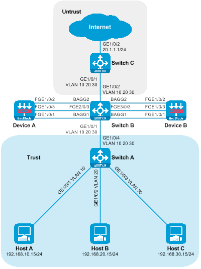
Figure 34 Side-mounted primary and backup deployment of SecBlade module with a layer 2 diversion logic group network diagram.
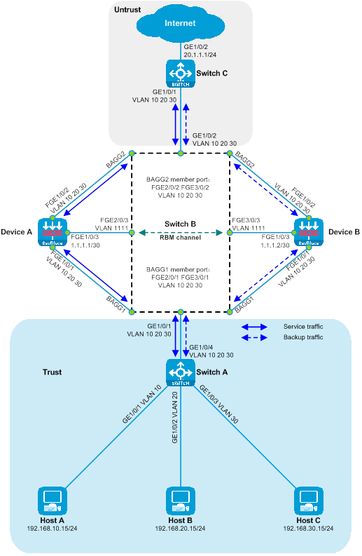
|
Device |
Interface |
IP address |
|
Host A |
N/A |
192.168.10.15/24 |
|
Host B |
N/A |
192.168.20.15/24 |
|
Host C |
N/A |
192.168.30.15/24 |
|
Switch C |
Vlan-interface10 |
192.168.10.1/24 |
|
|
Vlan-interface20 |
192.168.20.1/24 |
|
|
Vlan-interface30 |
192.168.30.1/24 |
|
|
GE1/0/2 |
20.1.1.1/24 |
|
Device A |
FGE1/0/3 |
1.1.1.1/30 |
|
Device B |
FGE1/0/3 |
1.1.1.2/30 |
Procedures
Configuring Switch A
Create VLAN 10, VLAN 20, and VLAN 30. Add GigabitEthernet1/0/1, GigabitEthernet1/0/2, and GigabitEthernet1/0/3 to VLAN 10, VLAN 20, and VLAN 30 respectively.
<SwitchA> system-view
[SwitchA] vlan 10
[SwitchA-vlan10] port gigabitethernet 1/0/1
[SwitchA-vlan10] quit
[SwitchA] vlan 20
[SwitchA-vlan20] port gigabitethernet 1/0/2
[SwitchA-vlan20] quit
[SwitchA] vlan 30
[SwitchA-vlan30] port gigabitethernet 1/0/3
[SwitchA-vlan30] quit
Configure the link type of GigabitEthernet1/0/4 as Trunk, and allow packets from VLAN 10, VLAN 20, and VLAN 30 to pass through.
[SwitchA] interface gigabitethernet 1/0/4
[SwitchA-GigabitEthernet1/0/4] port link-type trunk
[SwitchA-GigabitEthernet1/0/4] port trunk permit vlan 10 20 30
[SwitchA-GigabitEthernet1/0/4] quit
Configuring Switch B
Create VLAN 10, VLAN 20, VLAN 30, and VLAN 1111, and add FortyGigE2/0/3 and FortyGigE3/0/3 to VLAN 1111.
<SwitchB> system-view
[SwitchB] vlan 10
[SwitchB-vlan10] quit
[SwitchB] vlan 20
[SwitchB-vlan20] quit
[SwitchB] vlan 30
[SwitchB-vlan30] quit
[SwitchB] vlan 1111
[SwitchB-vlan1111] port fortygige 2/0/3 fortygige3/0/3
[SwitchB-vlan1111] quit
Create aggregation interface 1 and 2 at the Layer 2. Add ports FortyGigE2/0/1 and FortyGigE3/0/1 to aggregation group 1, and ports FortyGigE2/0/2 and FortyGigE3/0/2 to aggregation group 2.
[SwitchB] interface bridge-aggregation 1
[SwitchB-Bridge-Aggregation1] quit
[SwitchB] interface bridge-aggregation 2
[SwitchB-Bridge-Aggregation2] quit
[SwitchB] interface range fortygige 2/0/1 fortygige 3/0/1
[SwitchB-if-range] port link-aggregation group 1
[SwitchB-if-range] quit
[SwitchB] interface range fortygige 2/0/2 fortygige 3/0/2
[SwitchB-if-range] port link-aggregation group 2
[SwitchB-if-range] quit
Turn off the MAC address learning function (to prevent MAC wander) for Layer 2 aggregation interfaces 1 and 2, and disable the Spanning Tree Protocol (STP) (to prevent the ability of STP protocol to close port forwarding and receiving messages). Set the maximum selected port number for the aggregation group to 1.
[SwitchB] interface range bridge-aggregation 1 bridge-aggregation 2
[SwitchB-if-range] undo mac-address mac-learning enable
[SwitchB-if-range] undo stp enable
[SwitchB-if-range] link-aggregation selected-port maximum 1
[SwitchB-if-range] quit
Configure the port privilege level of
FortyGigE2/0/1 and FortyGigE2/0/2 to 0, to preferentially process service
through the interface that connects to Device A in the aggregation group.
[SwitchB] interface range fortygige 2/0/1 fortygige 2/0/2
[SwitchB-if-range] link-aggregation port-priority 0
[SwitchB-if-range] quit
Configure the link types of GigabitEthernet1/0/1, GigabitEthernet1/0/2, Layer 2 aggregation interface 1, and 2 as Trunk, and permit VLAN 10, VLAN 20, and VLAN 30 packets to pass.
[SwitchB] interface range gigabitethernet 1/0/1 gigabitethernet 1/0/2 bridge-aggregation 1 bridge-aggregation 2
[SwitchB-if-range] port link-type trunk
[SwitchB-if-range] port trunk permit vlan 10 20 30
[SwitchB-if-range] quit
Define a class to match VLAN 10, VLAN 20, and VLAN 30.
[SwitchB] traffic classifier servicevlan
[SwitchB-classifier-host-out] if-match service-vlan-id 10 20 30
[SwitchB-classifier-host-out] quit
Define the traffic behavior, the action is to redirect to the corresponding interface.
[SwitchB] traffic behavior gigabitethernet1/0/1
[SwitchB-behavior-gigabitethernet1/0/1] redirect interface gigabitethernet 1/0/1
[SwitchB-behavior-gigabitethernet1/0/1] quit
[SwitchB] traffic behavior gigabitethernet1/0/2
[SwitchB-behavior-gigabitethernet1/0/2] redirect interface gigabitethernet 1/0/2
[SwitchB-behavior-gigabitethernet1/0/2] quit
[SwitchB] traffic behavior bagg1
[SwitchB-behavior-bagg1] redirect interface bridge-aggregation 1
[SwitchB-behavior-bagg1] quit
[SwitchB] traffic behavior bagg2
[SwitchB-behavior-bagg2] redirect interface bridge-aggregation 2
[SwitchB-behavior-bagg2] quit
Define policy, assign traffic behavior to class.
[SwitchB] qos policy gigabitethernet1/0/1
[SwitchB-qospolicy-gigabitethernet1/0/1] classifier servicevlan behavior gigabitethernet1/0/1
[SwitchB-qospolicy-gigabitethernet1/0/1] quit
[SwitchB] qos policy gigabitethernet1/0/2
[SwitchB-qospolicy-gigabitethernet1/0/2] classifier servicevlan behavior gigabitethernet1/0/2
[SwitchB-qospolicy-gigabitethernet1/0/2] quit
[SwitchB] qos policy bagg1
[SwitchB-qospolicy-bagg1] classifier servicevlan behavior bagg1
[SwitchB-qospolicy-bagg1] quit
[SwitchB] qos policy bagg2
[SwitchB-qospolicy-bagg2] classifier servicevlan behavior bagg2
[SwitchB-qospolicy-bagg2] quit
Apply the policy to the input direction of the port.
[SwitchB] interface gigabitethernet 1/0/1
[SwitchB-GigabitEthernet1/0/1] qos apply policy bagg1 inbound
[SwitchB-GigabitEthernet1/0/1] quit
[SwitchB] interface gigabitethernet 1/0/2
[SwitchB-GigabitEthernet1/0/2] qos apply policy bagg2 inbound
[SwitchB-GigabitEthernet1/0/2] quit
[SwitchB] interface fortygige 2/0/1
[SwitchB-FortyGigE2/0/1] qos apply policy gigabitethernet1/0/1 inbound
[SwitchB-FortyGigE2/0/1] quit
[SwitchB] interface fortygige 2/0/2
[SwitchB-FortyGigE2/0/2] qos apply policy gigabitethernet1/0/2 inbound
[SwitchB-FortyGigE2/0/2] quit
[SwitchB] interface fortygige 3/0/1
[SwitchB-FortyGigE3/0/1] qos apply policy gigabitethernet1/0/1 inbound
[SwitchB-FortyGigE3/0/1] quit
[SwitchB] interface fortygige 3/0/2
[SwitchB-FortyGigE3/0/2] qos apply policy gigabitethernet1/0/2 inbound
[SwitchB-FortyGigE3/0/2] quit
Configuring Switch C
Create VLAN 10, VLAN 20, and VLAN 20.
<SwitchC> system-view
[SwitchC] vlan 10
[SwitchC-vlan10] quit
[SwitchC] vlan 20
[SwitchC-vlan20] quit
[SwitchC] vlan 30
[SwitchC-vlan30] quit
Configure the link type of GigabitEthernet1/0/1 as Trunk, and allow packets from VLAN 10, VLAN 20, and VLAN 20 to pass through.
[SwitchC] interface gigabitethernet 1/0/1
[SwitchC-GigabitEthernet1/0/1] port link-type trunk
[SwitchC-GigabitEthernet1/0/1] port trunk permit vlan 10 20 30
[SwitchC-GigabitEthernet1/0/1] quit
Create interfaces for VLAN 10, VLAN 20 and VLAN 30, and configure the IP address for the VLAN interfaces.
[SwitchC] interface vlan-interface 10
[SwitchC-Vlan-interface10] ip address 192.168.10.1 24
[SwitchC-Vlan-interface10] quit
[SwitchC] interface vlan-interface 20
[SwitchC-Vlan-interface20] ip address 192.168.20.1 24
[SwitchC-Vlan-interface20] quit
[SwitchC] interface vlan-interface 30
[SwitchC-Vlan-interface30] ip address 192.168.30.1 24
[SwitchC-Vlan-interface30] quit
Switch the operating mode of GigabitEthernet1/0/2 to layer 3 and configure the IP address.
[SwitchC] interface gigabitethernet 1/0/2
[SwitchC-GigabitEthernet1/0/2] port link-mode route
The configuration of the interface will be restored to the default. Continue? [Y]:y
[SwitchC-GigabitEthernet1/0/2] ip address 20.1.1.1 24
[SwitchC-GigabitEthernet1/0/2] quit
Configure Device A
Create VLAN10, VLAN20, and VLAN30.
<DeviceA> system-view
[DeviceA] vlan 10
[DeviceA-vlan10] quit
[DeviceA] vlan 20
[DeviceA-vlan20] quit
[DeviceA] vlan 30
[DeviceA-vlan30] quit
Switch the working modes of FortyGigE1/0/1 and FortyGigE1/0/2 to Layer 2 mode.
[DeviceA] interface range fortygige 1/0/1 fortygige 1/0/2
[DeviceA-if-range] port link-mode bridge
[DeviceA-if-range] quit
Configure the link types of FortyGigE1/0/1 and FortyGigE1/0/2 as Trunk, and allow packets from VLAN 10, VLAN 20 and VLAN 30 to pass.
[DeviceA] interface range fortygige 1/0/1 fortygige 1/0/2
[DeviceA-if-range] port link-type trunk
[DeviceA-if-range] port trunk permit vlan 10 20 30
[DeviceA-if-range] quit
Add VLAN10, VLAN20, and VLAN30 of FortyGigE1/0/1 to the security zone Trust, and add VLAN10, VLAN20, and VLAN30 of FortyGigE1/0/2 to the security zone Untrust.
[DeviceA] security-zone name trust
[DeviceA-security-zone-Trust] import interface fortygige 1/0/1 vlan 10 20 30
[DeviceA-security-zone-Trust] quit
[DeviceA] security-zone name untrust
[DeviceA-security-zone-Untrust] import interface fortygige 1/0/2 vlan 10 20 30
[DeviceA-security-zone-Untrust] quit
Configure the security policy to allow messages between domains to pass.
[DeviceA] security-policy ip
[DeviceA-security-policy-ip] rule name trust-untrust
[DeviceA-security-policy-ip-0-trust-untrust] action pass
[DeviceA-security-policy-ip-0-trust-untrust] source-zone trust
[DeviceA-security-policy-ip-0-trust-untrust] destination-zone untrust
[DeviceA-security-policy-ip-0-trust-untrust] quit
[DeviceA-security-policy-ip] rule name untrust-trust
[DeviceA-security-policy-ip-1-untrust-trust] action pass
[DeviceA-security-policy-ip-1-untrust-trust] source-zone untrust
[DeviceA-security-policy-ip-1-untrust-trust] destination-zone trust
[DeviceA-security-policy-ip-1-untrust-trust] quit
[DeviceA-security-policy-ip] quit
Configure the IP address of the FortyGigE1/0/3 interface.
[DeviceA] interface fortygige 1/0/3
[DeviceA-FortyGigE1/0/3] ip address 1.1.1.1 30
[DeviceA-FortyGigE1/0/3] quit
Configure high availability (HA) RBM, monitor the state of FortyGigE1/0/1 and FortyGigE1/0/2 interfaces.
[DeviceA] remote-backup group
[DeviceA-remote-backup-group] remote-ip 1.1.1.2
[DeviceA-remote-backup-group] local-ip 1.1.1.1
[DeviceA-remote-backup-group] data-channel interface fortygige 1/0/3
[DeviceA-remote-backup-group] device-role primary
RBM_P[DeviceA-remote-backup-group] track interface fortygige 1/0/1
RBM_P[DeviceA-remote-backup-group] track interface fortygige 1/0/2
RBM_P[DeviceA-remote-backup-group] quit
Configure Device B
Create VLAN10, VLAN20, and VLAN30.
<DeviceB> system-view
[DeviceB] vlan 10
[DeviceB-vlan10] quit
[DeviceB] vlan 20
[DeviceB-vlan20] quit
[DeviceB] vlan 30
[DeviceB-vlan30] quit
Switch the working mode of FortyGigE1/0/1 and FortyGigE1/0/2 to layer 2 mode.
[DeviceB] interface range fortygige 1/0/1 fortygige 1/0/2
[DeviceB-if-range] port link-mode bridge
[DeviceB-if-range] quit
Configure the link type of FortyGigE1/0/1 and FortyGigE1/0/2 as Trunk, and allow packets from VLAN 10, VLAN 20, and VLAN 30 to pass through.
[DeviceB] interface range fortygige 1/0/1 fortygige 1/0/2
[DeviceB-if-range] port link-type trunk
[DeviceB-if-range] port trunk permit vlan 10 20 30
[DeviceB-if-range] quit
Add VLAN 10, VLAN 20, and VLAN 30 of FortyGigE1/0/1 to the security domain Trust, and add VLAN 10, VLAN 20, and VLAN 30 of FortyGigE1/0/2 to the security domain Untrust.
[DeviceB] security-zone name trust
[DeviceB-security-zone-Trust] import interface fortygige 1/0/1 vlan 10 20 30
[DeviceB-security-zone-Trust] quit
[DeviceB] security-zone name untrust
[DeviceB-security-zone-Untrust] import interface fortygige 1/0/2 vlan 10 20 30
[DeviceB-security-zone-Untrust] quit
Configure the security policy to allow inter-domain messages to pass.
[DeviceB] security-policy ip
[DeviceB-security-policy-ip] rule name trust-untrust
[DeviceB-security-policy-ip-0-trust-untrust] action pass
[DeviceB-security-policy-ip-0-trust-untrust] source-zone trust
[DeviceB-security-policy-ip-0-trust-untrust] destination-zone untrust
[DeviceB-security-policy-ip-0-trust-untrust] quit
[DeviceB-security-policy-ip] rule name untrust-trust
[DeviceB-security-policy-ip-1-untrust-trust] action pass
[DeviceB-security-policy-ip-1-untrust-trust] source-zone untrust
[DeviceB-security-policy-ip-1-untrust-trust] destination-zone trust
[DeviceB-security-policy-ip-1-untrust-trust] quit
[DeviceB-security-policy-ip] quit
Configure the IP address for FortyGigE1/0/3 interface.
[DeviceB] interface fortygige 1/0/3
[DeviceB-FortyGigE1/0/3] ip address 1.1.1.2 30
[DeviceB-FortyGigE1/0/3] quit
Configure high availability (HA) RBM, monitoring the state of FortyGigE1/0/1 and FortyGigE1/0/2 interfaces.
[DeviceB] remote-backup group
[DeviceB-remote-backup-group] remote-ip 1.1.1.1
[DeviceB-remote-backup-group] local-ip 1.1.1.2
[DeviceB-remote-backup-group] data-channel interface fortygige 1/0/3
[DeviceB-remote-backup-group] device-role secondary
RBM_S[DeviceB-remote-backup-group] track interface fortygige 1/0/1
RBM_S[DeviceB-remote-backup-group] track interface fortygige 1/0/2
RBM_S[DeviceB-remote-backup-group] quit
Verifying the configuration
To check if the HA configuration is effective and whether the HA channel is established, execute the following display command on Device A.
RBM_P[DeviceA] display remote-backup-group status
Remote backup group information:
Backup mode: Active/standby
Device management role: Primary
Device running status: Active
Data channel interface: FortyGigE1/0/3
Local IP: 1.1.1.1
Remote IP: 1.1.1.2 Destination port: 60064
Control channel status: Connected
Keepalive interval: 1s
Keepalive count: 10
Configuration consistency check interval: 12 hour
Configuration consistency check result: Not Performed
Configuration backup status: Auto sync enabled
Session backup status: Hot backup enabled
Uptime since last switchover: 0 days, 3 hours, 11 minutes
Switchover records:
Time Status change Cause
2021-06-22 13:33:33 Initial to Active Interface status changed
Execute the following display command on Device B to check if the HA configuration is effective, and if the HA channel is established.
RBM_S[DeviceB] display remote-backup-group status
Remote backup group information:
Backup mode: Active/standby
Device management role: Secondary
Device running status: Standby
Data channel interface: FortyGigE1/0/3
Local IP: 1.1.1.2
Remote IP: 1.1.1.1 Destination port: 60064
Control channel status: Connected
Keepalive interval: 1s
Keepalive count: 10
Configuration consistency check interval: 12 hour
Configuration consistency check result: Not Performed
Configuration backup status: Auto sync enabled
Session backup status: Hot backup enabled
Uptime since last switchover: 0 days, 3 hours, 12 minutes
Switchover records:
Time Status change Cause
2022-06-22 13:34:34 Initial to Standby Interface status changed
# A ping test on Host A to check the connectivity of the Internet is successful, as it can ping the Internet address 20.1.1.1.
C:\>ping 20.1.1.1
Pinging 20.1.1.1 with 32 bytes of data:
Reply from 20.1.1.1: bytes=32 time=3ms TTL=254
Reply from 20.1.1.1: bytes=32 time=2ms TTL=254
Reply from 20.1.1.1: bytes=32 time=1ms TTL=254
Reply from 20.1.1.1: bytes=32 time=2ms TTL=254
Ping statistics for 20.1.1.1:
Packets: Sent = 4, Received = 4, Lost = 0 (0% loss),
Approximate round trip times in milli-seconds:
Minimum = 1ms, Maximum = 3ms, Average = 2ms
On Host B, perform a ping test for Internet connectivity; it successfully pings the Internet address 20.1.1.1.
C:\>ping 20.1.1.1
Pinging 20.1.1.1 with 32 bytes of data:
Reply from 20.1.1.1: bytes=32 time=3ms TTL=254
Reply from 20.1.1.1: bytes=32 time=2ms TTL=254
Reply from 20.1.1.1: bytes=32 time=1ms TTL=254
Reply from 20.1.1.1: bytes=32 time=2ms TTL=254
Ping statistics for 20.1.1.1:
Packets: Sent = 4, Received = 4, Lost = 0 (0% loss),
Approximate round trip times in milli-seconds:
Minimum = 1ms, Maximum = 3ms, Average = 2ms
Host C is conducting a ping test on the internet connectivity, it can successfully ping the internet address 20.1.1.1.
C:\>ping 20.1.1.1
Pinging 20.1.1.1 with 32 bytes of data:
Reply from 20.1.1.1: bytes=32 time=3ms TTL=254
Reply from 20.1.1.1: bytes=32 time=2ms TTL=254
Reply from 20.1.1.1: bytes=32 time=1ms TTL=254
Reply from 20.1.1.1: bytes=32 time=2ms TTL=254
Ping statistics for 20.1.1.1:
Packets: Sent = 4, Received = 4, Lost = 0 (0% loss),
Approximate round trip times in milli-seconds:
Minimum = 1ms, Maximum = 3ms, Average = 2ms
Check the session table on the Device, where exists a session table between the Host and 20.1.1.1.
RBM_P[DeviceA] display session table ipv4
Slot 1:
Initiator:
Source IP/port: 192.168.10.15/12005
Destination IP/port: 20.1.1.1/2048
DS-Lite tunnel peer: -
VPN instance/VLAN ID/Inline ID: -/10/-
Protocol: ICMP(1)
Inbound interface: FortyGigE1/0/1
Source security zone: Trust
Initiator:
Source IP/port: 192.168.20.15/12005
Destination IP/port: 20.1.1.1/2048
DS-Lite tunnel peer: -
VPN instance/VLAN ID/Inline ID: -/20/-
Protocol: ICMP(1)
Inbound interface: FortyGigE1/0/1
Source security zone: Trust
Initiator:
Source IP/port: 192.168.30.15/12005
Destination IP/port: 20.1.1.1/2048
DS-Lite tunnel peer: -
VPN instance/VLAN ID/Inline ID: -/30/-
Protocol: ICMP(1)
Inbound interface: FortyGigE1/0/1
Source security zone: Trust
Configuration file
Switch A
#
vlan 10
#
vlan 20
#
vlan 30
#
interface GigabitEthernet1/0/1
port access vlan 10
#
interface GigabitEthernet1/0/2
port access vlan 20
#
interface GigabitEthernet1/0/3
port access vlan 30
#
interface GigabitEthernet1/0/4
port link-type trunk
port trunk permit vlan 10 20 30
#
Switch B
#
vlan 10
#
vlan 20
#
vlan 30
#
vlan 1111
#
traffic classifier servicevlan
if-match service-vlan-id 10 20 30
#
traffic behavior bagg1
redirect interface Bridge-Aggregation1
#
traffic behavior bagg2
redirect interface Bridge-Aggregation2
#
traffic behavior gigabitethernet1/0/1
redirect interface GigabitEthernet1/0/1
#
traffic behavior gigabitethernet1/0/2
redirect interface GigabitEthernet1/0/2
#
qos policy bagg1
classifier servicevlan behavior bagg1
#
qos policy bagg2
classifier servicevlan behavior bagg2
#
qos policy gigabitethernet1/0/1
classifier servicevlan behavior gigabitethernet1/0/1
#
qos policy gigabitethernet1/0/2
classifier servicevlan behavior gigabitethernet1/0/2
#
interface Bridge-Aggregation1
port link-type trunk
port trunk permit vlan 10 20 30
link-aggregation selected-port maximum 1
undo stp enable
undo mac-address mac-learning enable
#
interface Bridge-Aggregation2
port link-type trunk
port trunk permit vlan 10 20 30
link-aggregation selected-port maximum 1
undo stp enable
undo mac-address mac-learning enable
#
interface GigabitEthernet1/0/1
port link-type trunk
port trunk permit vlan 10 20 30
qos apply policy bagg1 inbound
#
interface GigabitEthernet1/0/2
port link-type trunk
port trunk permit vlan 10 20 30
qos apply policy bagg2 inbound
#
interface FortyGigE2/0/1
port link-type trunk
port trunk permit vlan 10 20 30
qos apply policy gigabitethernet1/0/1 inbound
link-aggregation port-priority 0
port link-aggregation group 1
#
interface FortyGigE2/0/2
port link-type trunk
port trunk permit vlan 10 20 30
qos apply policy gigabitethernet1/0/2 inbound
link-aggregation port-priority 0
port link-aggregation group 1
#
interface FortyGigE2/0/3
port access vlan 1111
#
interface FortyGigE3/0/1
port link-type trunk
port trunk permit vlan 10 20 30
qos apply policy gigabitethernet1/0/1 inbound
port link-aggregation group 1
#
interface FortyGigE3/0/2
port link-type trunk
port trunk permit vlan 10 20 30
qos apply policy gigabitethernet1/0/2 inbound
port link-aggregation group 2
#
interface FortyGigE3/0/3
port access vlan 1111
#
Switch C
#
vlan 10
#
vlan 20
#
vlan 30
#
interface Vlan-interface10
ip address 192.168.10.1 255.255.255.0
#
interface Vlan-interface20
ip address 192.168.20.1 255.255.255.0
#
interface Vlan-interface30
ip address 192.168.30.1 255.255.255.0
#
interface GigabitEthernet1/0/2
port link-mode route
ip address 20.1.1.1 255.255.255.0
#
interface GigabitEthernet1/0/1
port link-type trunk
port trunk permit vlan 10 20 30
#
Device A
#
vlan 10
#
vlan 20
#
vlan 30
#
interface FortyGigE1/0/3
ip address 1.1.1.1 255.255.255.252
#
interface FortyGigE1/0/1
port link-mode bridge
port link-type trunk
port trunk permit vlan 10 20 30
#
interface FortyGigE1/0/2
port link-mode bridge
port link-type trunk
port trunk permit vlan 10 20 30
#
security-zone name Trust
import interface FortyGigE1/0/1 vlan 10 20 30
#
security-zone name Untrust
import interface FortyGigE1/0/2 vlan 10 20 30
#
security-policy ip
rule 0 name trust-untrust
action pass
source-zone trust
destination-zone untrust
rule 1 name untrust-trust
action pass
source-zone untrust
destination-zone trust
#
remote-backup group
data-channel interface FortyGigE1/0/3
track interface FortyGigE1/0/1
track interface FortyGigE1/0/2
local-ip 1.1.1.1
remote-ip 1.1.1.2
device-role primary
#
Device B
#
vlan 10
#
vlan 20
#
vlan 30
#
interface FortyGigE1/0/3
ip address 1.1.1.2 255.255.255.252
#
interface FortyGigE1/0/1
port link-mode bridge
port link-type trunk
port trunk permit vlan 10 20 30
#
interface FortyGigE1/0/2
port link-mode bridge
port link-type trunk
port trunk permit vlan 10 20 30
#
security-zone name Trust
import interface FortyGigE1/0/1 vlan 10 20 30
#
security-zone name Untrust
import interface FortyGigE1/0/2 vlan 10 20 30
#
security-policy ip
rule 0 name trust-untrust
action pass
source-zone trust
destination-zone untrust
rule 1 name untrust-trust
action pass
source-zone untrust
destination-zone trust
#
remote-backup group
data-channel interface FortyGigE1/0/3
track interface FortyGigE1/0/1
track interface FortyGigE1/0/2
local-ip 1.1.1.2
remote-ip 1.1.1.1
device-role secondary
#
Transparent primary and secondary direct path SecBlade module deployment
Network configuration
Host A, Host B, and Host C communicate with the Internet through access switch Switch A, aggregation switch Switch B, and core switch Switch C. For security reasons, two SecBlade modules, Device A and Device B, need to be deployed on aggregation switch Switch B for security protection. The application requirements are as follows:
· Switch A assigns Host A, Host B, and Host C to VLAN 10, VLAN 20, and VLAN 30 respectively, transmitting the traffic between the Host and the Internet.
· Switch B allocates downstream service ports to VLAN 10, VLAN 20, and VLAN 30, while upstream service ports are allocated to VLAN 40, VLAN 50, and VLAN 60. The interconnection ports with Device are assigned to VLAN 10, VLAN 20, VLAN 30, VLAN 40, VLAN 50, and VLAN 60, enabling transparent transmission of traffic between Host and Internet to Device in both upstream and downstream directions.
· The downstream services of the device are divided into VLAN 10, VLAN 20, and VLAN 30, while the upstream services are segmented into VLAN 40, VLAN 50, and VLAN 60. The device redirects traffic between the host and the Internet across VLANs. Device A and Device B serve as the main and backup units, respectively.
· Switch C acts as the gateway for Host A, Host B, and Host C, checking the routing table to forward traffic between the host and the Internet.
Figure 35 Network Diagram of Primary and Backup Deployment of SecBlade module via Transparent Direct Route

Figure 36 Network diagram showing the primary-secondary deployment of SecBlade module with transparent straight-through logic grouping.
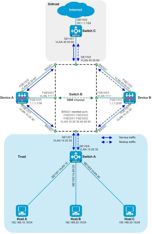
|
Device |
Interface |
IP address |
|
Host A |
N/A |
192.168.10.15/24 |
|
Host B |
N/A |
192.168.20.15/24 |
|
Host C |
N/A |
192.168.30.15/24 |
|
Switch C |
Vlan-interface40 |
192.168.10.1/24 |
|
|
Vlan-interface50 |
192.168.20.1/24 |
|
|
Vlan-interface60 |
192.168.30.1/24 |
|
|
GE1/0/2 |
20.1.1.1/24 |
|
Device A |
|
1.1.1.1/30 |
|
Device B |
|
1.1.1.2/30 |
Procedures
Configuring Switch A
Create VLAN 10, VLAN 20, and VLAN 30. Add GigabitEthernet1/0/1, GigabitEthernet1/0/2, and GigabitEthernet1/0/3 to VLAN 10, VLAN 20, and VLAN 30, respectively.
<SwitchA> system-view
[SwitchA] vlan 10
[SwitchA-vlan10] port gigabitethernet 1/0/1
[SwitchA-vlan10] quit
[SwitchA] vlan 20
[SwitchA-vlan20] port gigabitethernet 1/0/2
[SwitchA-vlan20] quit
[SwitchA] vlan 30
[SwitchA-vlan30] port gigabitethernet 1/0/3
[SwitchA-vlan30] quit
Configure the link type of GigabitEthernet1/0/4 as Trunk, and allow messages from VLAN 10, VLAN 20 and VLAN 30 to pass through.
[SwitchA] interface gigabitethernet 1/0/4
[SwitchA-GigabitEthernet1/0/4] port link-type trunk
[SwitchA-GigabitEthernet1/0/4] port trunk permit vlan 10 20 30
[SwitchA-GigabitEthernet1/0/4] quit
Configuring Switch B
Create VLAN 10, VLAN 20, VLAN 30, VLAN
40, VLAN 50, VLAN 60, and VLAN 1111, then add FortyGigE2/0/3 and FortyGigE3/0/3
to VLAN 1111.
<SwitchB> system-view
[SwitchB] vlan 10
[SwitchB-vlan10] quit
[SwitchB] vlan 20
[SwitchB-vlan20] quit
[SwitchB] vlan 30
[SwitchB-vlan30] quit
[SwitchB] vlan 40
[SwitchB-vlan40] quit
[SwitchB] vlan 50
[SwitchB-vlan50] quit
[SwitchB] vlan 60
[SwitchB-vlan60] quit
[SwitchB] vlan 1111
[SwitchA-vlan1111] port fortygige 2/0/3 fortygige 3/0/3
[SwitchB-vlan1111] quit
Configure the link type of GigabitEthernet1/0/1 as Trunk, and allow messages of VLAN 10, VLAN 20, and VLAN 30 to pass.
[SwitchB] interface gigabitethernet 1/0/1
[SwitchB-GigabitEthernet1/0/1] port link-type trunk
[SwitchB-GigabitEthernet1/0/1] port trunk permit vlan 10 20 30
[SwitchB-GigabitEthernet1/0/1] quit
Configure the link type of GigabitEthernet1/0/2 as Trunk, and allow the messages of VLAN 40, VLAN 50, and VLAN 60 to pass.
[SwitchB] interface gigabitethernet 1/0/2
[SwitchB-GigabitEthernet1/0/2] port link-type trunk
[SwitchB-GigabitEthernet1/0/2] port trunk permit vlan 40 50 60
[SwitchB-GigabitEthernet1/0/2] quit
Create a Layer 2 aggregation interface 1 as a Trunk port, and allow packets from VLAN 10, VLAN 20, VLAN 30, VLAN 40, VLAN 50, and VLAN 60 to pass through.
[SwitchB] interface bridge-aggregation 1
[SwitchB-Bridge-Aggregation1] port link-type trunk
[SwitchB-Bridge-Aggregation1] port trunk permit vlan 10 20 30 40 50 60
[SwitchB-Bridge-Aggregation1] quit
Add the ports FortyGigE2/0/1, FortyGigE2/0/2, FortyGigE3/0/1, and FortyGigE3/0/2 to the aggregation group 1.
[SwitchB] interface range fortygige 2/0/1 fortygige 2/0/2 fortygige 3/0/1 fortygige 3/0/2
[SwitchB-if-range] port link-aggregation group 1
[SwitchB-if-range] quit
Configure the maximum selected port number for aggregation group 1 to be 2, and close the Spanning Tree Protocol to prevent the STP reconvergence caused by RBM switchover, which could briefly disrupt service.
[SwitchB] interface bridge-aggregation 1
[SwitchB-Bridge-Aggregation1] link-aggregation selected-port maximum 2
[SwitchB-Bridge-Aggregation1] undo stp enable
[SwitchB-Bridge-Aggregation1] quit
Configure the port priority of FortyGigE2/0/1 and FortyGigE2/0/2 to 0, so that the aggregation group prefers to process service through the interface connected to Device A.
[SwitchB] interface range fortygige 2/0/1 fortygige 2/0/2
[SwitchB-if-range] link-aggregation port-priority 0
[SwitchB-if-range] quit
Configuring Switch C
Create VLAN 40, VLAN 50, and VLAN 60.
<SwitchC> system-view
[SwitchC] vlan 40
[SwitchC-vlan40] quit
[SwitchC] vlan 50
[SwitchC-vlan50] quit
[SwitchC] vlan 60
[SwitchC-vlan60] quit
Configure the link type for GigabitEthernet1/0/1 as Trunk, and allow packets from VLAN 40, VLAN 50, and VLAN 60 to pass through.
[SwitchC] interface gigabitethernet 1/0/1
[SwitchC-GigabitEthernet1/0/1] port link-type trunk
[SwitchC-GigabitEthernet1/0/1] port trunk permit vlan 40 50 60
[SwitchC-GigabitEthernet1/0/1] quit
Create interfaces for VLAN 40, VLAN 50, and VLAN 60, and configure the IP address for each VLAN interface.
[SwitchC] interface vlan-interface 40
[SwitchC-Vlan-interface40] ip address 192.168.10.1 24
[SwitchC-Vlan-interface40] quit
[SwitchC] interface vlan-interface 50
[SwitchC-Vlan-interface50] ip address 192.168.20.1 24
[SwitchC-Vlan-interface50] quit
[SwitchC] interface vlan-interface 60
[SwitchC-Vlan-interface60] ip address 192.168.30.1 24
[SwitchC-Vlan-interface60] quit
Switch the operating mode of GigabitEthernet1/0/2 to layer three (stratum), and configure the IP address.
[SwitchC] interface gigabitethernet 1/0/2
[SwitchC-GigabitEthernet1/0/2] port link-mode route
The configuration of the interface will be restored to the default. Continue? [Y]:y
[SwitchC-GigabitEthernet1/0/2] ip address 20.1.1.1 24
[SwitchC-GigabitEthernet1/0/2] quit
Configure Device A
Create VLAN10, VLAN20, VLAN30, VLAN40, VLAN50, and VLAN60.
<DeviceA> system-view
[DeviceA] vlan 10
[DeviceA-vlan10] quit
[DeviceA] vlan 20
[DeviceA-vlan20] quit
[DeviceA] vlan 30
[DeviceA-vlan30] quit
[DeviceA] vlan 40
[DeviceA-vlan40] quit
[DeviceA] vlan 50
[DeviceA-vlan50] quit
[DeviceA] vlan 60
[DeviceA-vlan60] quit
Switch the working mode of FortyGigE1/0/1 and FortyGigE1/0/2 to Layer 2 and configure the link type as Trunk. Allow messages from VLAN 10, VLAN 20, VLAN 30, VLAN 40, VLAN 50, VLAN 60 to pass through.
[DeviceA] interface range fortygige 1/0/1 fortygige 1/0/2
[DeviceA-if-range] port link-mode bridge
[DeviceA-if-range] port link-type trunk
[DeviceA-if-range] port trunk permit vlan 10 20 30 40 50 60
[DeviceA-if-range] quit
Configure the IP address for the FortyGigE1/0/3 interface.
[DeviceA] interface fortygige 1/0/3
[DeviceA-FortyGigE1/0/3] ip address 1.1.1.1 30
[DeviceA-FortyGigE1/0/3] quit
Add VLAN10, VLAN20, VLAN30 to the security domain Trust, and VLAN40, VLAN50, VLAN60 to the security domain Untrust.
[DeviceA] security-zone name trust
[DeviceA-security-zone-Trust] import vlan 10 20 30
[DeviceA-security-zone-Trust] quit
[DeviceA] security-zone name untrust
[DeviceA-security-zone-Untrust] import vlan 40 50 60
[DeviceA-security-zone-Untrust] quit
Configure the security policy to allow domain messages to pass.
[DeviceA] security-policy ip
[DeviceA-security-policy-ip] rule name trust-untrust
[DeviceA-security-policy-ip-0-trust-untrust] action pass
[DeviceA-security-policy-ip-0-trust-untrust] source-zone trust
[DeviceA-security-policy-ip-0-trust-untrust] destination-zone untrust
[DeviceA-security-policy-ip-0-trust-untrust] quit
[DeviceA-security-policy-ip] rule name untrust-trust
[DeviceA-security-policy-ip-1-untrust-trust] action pass
[DeviceA-security-policy-ip-1-untrust-trust] source-zone untrust
[DeviceA-security-policy-ip-1-untrust-trust] destination-zone trust
[DeviceA-security-policy-ip-1-untrust-trust] quit
[DeviceA-security-policy-ip] quit
Create forwarding instances Bridge 1, Bridge 2, and Bridge 3 for cross-VLAN forwarding mode and add the necessary VLANs for intercommunication to each instance.
[DeviceA] bridge 1 inter-vlan
[DeviceA-bridge-1-inter-vlan] add vlan 10 40
[DeviceA-bridge-1-inter-vlan] quit
[DeviceA] bridge 2 inter-vlan
[DeviceA-bridge-2-inter-vlan] add vlan 20 50
[DeviceA-bridge-2-inter-vlan] quit
[DeviceA] bridge 3 inter-vlan
[DeviceA-bridge-3-inter-vlan] add vlan 30 60
[DeviceA-bridge-3-inter-vlan] quit
Configure high availability (HA) RBM,
monitor the state of FortyGigE1/0/1 and FortyGigE1/0/2 interfaces.
[DeviceA] remote-backup group
[DeviceA-remote-backup-group] remote-ip 1.1.1.2
[DeviceA-remote-backup-group] local-ip 1.1.1.1
[DeviceA-remote-backup-group] data-channel interface FortyGigE 1/0/3
[DeviceA-remote-backup-group] device-role primary
RBM_P[DeviceA-remote-backup-group] track interface FortyGigE 1/0/1
RBM_P[DeviceA-remote-backup-group] track interface FortyGigE 1/0/2
RBM_P[DeviceA-remote-backup-group] quit
Configure Device B
Create VLAN10, VLAN20, VLAN30, VLAN40, VLAN50, and VLAN60.
<DeviceB> system-view
[DeviceB] vlan 10
[DeviceB-vlan10] quit
[DeviceB] vlan 20
[DeviceB-vlan20] quit
[DeviceB] vlan 30
[DeviceB-vlan30] quit
[DeviceB] vlan 40
[DeviceB-vlan40] quit
[DeviceB] vlan 50
[DeviceB-vlan50] quit
[DeviceB] vlan 60
[DeviceB-vlan60] quit
Switch the working mode of FortyGigE1/0/1 and FortyGigE1/0/2 to Layer 2 and configure the link type as Trunk, allowing packets from VLAN 10, VLAN 20, VLAN 30, VLAN 40, VLAN 50, and VLAN 60 to pass.
[DeviceB] interface range fortygige 1/0/1 fortygige 1/0/2
[DeviceB-if-range] port link-mode bridge
[DeviceB-if-range] port link-type trunk
[DeviceB-if-range] port trunk permit vlan 10 20 30 40 50 60
[DeviceB-if-range] quit
Configure the IP of interface FortyGigE1/0/3.
[DeviceB] interface fortygige 1/0/3
[DeviceB-FortyGigE1/0/3] ip address 1.1.1.2 30
[DeviceB-FortyGigE1/0/3] quit
Add VLAN10, VLAN20, and VLAN30 to the security domain Trust, and add VLAN40, VLAN50, and VLAN60 to the security domain Untrust.
[DeviceB] security-zone name trust
[DeviceB-security-zone-Trust] import vlan 10 20 30
[DeviceB-security-zone-Trust] quit
[DeviceB] security-zone name untrust
[DeviceB-security-zone-Untrust] import vlan 40 50 60
[DeviceB-security-zone-Untrust] quit
Configure the security policy to allow inter-domain messages to pass.
[DeviceB] security-policy ip
[DeviceB-security-policy-ip] rule name trust-untrust
[DeviceB-security-policy-ip-0-trust-untrust] action pass
[DeviceB-security-policy-ip-0-trust-untrust] source-zone trust
[DeviceB-security-policy-ip-0-trust-untrust] destination-zone untrust
[DeviceB-security-policy-ip-0-trust-untrust] quit
[DeviceB-security-policy-ip] rule name untrust-trust
[DeviceB-security-policy-ip-1-untrust-trust] action pass
[DeviceB-security-policy-ip-1-untrust-trust] source-zone untrust
[DeviceB-security-policy-ip-1-untrust-trust] destination-zone trust
[DeviceB-security-policy-ip-1-untrust-trust] quit
[DeviceB-security-policy-ip] quit
Create forwarding instances Bridge 1, Bridge 2, and Bridge 3 for the cross-VLAN forwarding mode, and add the VLANs that need intercommunication to the instances respectively.
[DeviceB] bridge 1 inter-vlan
[DeviceB-bridge-1-inter-vlan] add vlan 10 40
[DeviceB-bridge-1-inter-vlan] quit
[DeviceB] bridge 2 inter-vlan
[DeviceB-bridge-2-inter-vlan] add vlan 20 50
[DeviceB-bridge-2-inter-vlan] quit
[DeviceB] bridge 3 inter-vlan
[DeviceB-bridge-3-inter-vlan] add vlan 30 60
[DeviceB-bridge-3-inter-vlan] quit
Configure high availability (HA) RBM, monitor the state of FortyGigE1/0/1 and FortyGigE1/0/2 interfaces.
[DeviceB] remote-backup group
[DeviceB-remote-backup-group] remote-ip 1.1.1.1
[DeviceB-remote-backup-group] local-ip 1.1.1.2
[DeviceB-remote-backup-group] data-channel interface FortyGigE 1/0/3
[DeviceB-remote-backup-group] device-role secondary
RBM_S[DeviceB-remote-backup-group] track interface FortyGigE 1/0/1
RBM_S[DeviceB-remote-backup-group] track interface FortyGigE 1/0/2
RBM_S[DeviceB-remote-backup-group] quit
Verifying the configuration
To check if the HA configuration has taken effect and whether the HA channel has been established, execute the following display command on Device A.
RBM_P[DeviceA] display remote-backup-group status
Remote backup group information:
Backup mode: Active/standby
Device management role: Primary
Device running status: Active
Data channel interface: FortyGigE1/0/3
Local IP: 1.1.1.1
Remote IP: 1.1.1.2 Destination port: 60064
Control channel status: Connected
Keepalive interval: 1s
Keepalive count: 10
Configuration consistency check interval: 12 hour
Configuration consistency check result: Not Performed
Configuration backup status: Auto sync enabled
Session backup status: Hot backup enabled
Uptime since last switchover: 0 days, 3 hours, 11 minutes
Switchover records:
Time Status change Cause
2021-06-22 13:33:33 Initial to Active Interface status changed
To check whether the HA configuration has taken effect and whether an HA channel has been set up, execute the following display command on Device B.
RBM_S[DeviceB] display remote-backup-group status
Remote backup group information:
Backup mode: Active/standby
Device management role: Secondary
Device running status: Standby
Data channel interface: FortyGigE1/0/3
Local IP: 1.1.1.2
Remote IP: 1.1.1.1 Destination port: 60064
Control channel status: Connected
Keepalive interval: 1s
Keepalive count: 10
Configuration consistency check interval: 12 hour
Configuration consistency check result: Not Performed
Configuration backup status: Auto sync enabled
Session backup status: Hot backup enabled
Uptime since last switchover: 0 days, 3 hours, 12 minutes
Switchover records:
Time Status change Cause
2022-06-22 13:34:34 Initial to Standby Interface status changed
# Host A is testing the connectivity to the Internet by pinging. It can successfully ping the Internet address 20.1.1.1.
C:\>ping 20.1.1.1
Pinging 20.1.1.1 with 32 bytes of data:
Reply from 20.1.1.1: bytes=32 time=3ms TTL=254
Reply from 20.1.1.1: bytes=32 time=2ms TTL=254
Reply from 20.1.1.1: bytes=32 time=1ms TTL=254
Reply from 20.1.1.1: bytes=32 time=2ms TTL=254
Ping statistics for 20.1.1.1:
Packets: Sent = 4, Received = 4, Lost = 0 (0% loss),
Approximate round trip times in milli-seconds:
Minimum = 1ms, Maximum = 3ms, Average = 2ms
Host C conducts a ping test to check the connectivity with the Internet and successfully pings the Internet address 20.1.1.1.
C:\>ping 20.1.1.1
Pinging 20.1.1.1 with 32 bytes of data:
Reply from 20.1.1.1: bytes=32 time=3ms TTL=254
Reply from 20.1.1.1: bytes=32 time=2ms TTL=254
Reply from 20.1.1.1: bytes=32 time=1ms TTL=254
Reply from 20.1.1.1: bytes=32 time=2ms TTL=254
Ping statistics for 20.1.1.1:
Packets: Sent = 4, Received = 4, Lost = 0 (0% loss),
Approximate round trip times in milli-seconds:
Minimum = 1ms, Maximum = 3ms, Average = 2ms
Check the session table on the Device, there is a session table between the Host and 20.1.1.1.
RBM_P[DeviceA] display session table ipv4
Slot 1:
Initiator:
Source IP/port: 192.168.10.15/12005
Destination IP/port: 20.1.1.1/2048
DS-Lite tunnel peer: -
VPN instance/VLAN ID/Inline ID: -/10/-
Protocol: ICMP(1)
Inbound interface: FortyGigE1/0/1
Source security zone: Trust
Initiator:
Source IP/port: 192.168.20.15/12005
Destination IP/port: 20.1.1.1/2048
DS-Lite tunnel peer: -
VPN instance/VLAN ID/Inline ID: -/20/-
Protocol: ICMP(1)
Inbound interface: FortyGigE1/0/1
Source security zone: Trust
Initiator:
Source IP/port: 192.168.30.15/12005
Destination IP/port: 20.1.1.1/2048
DS-Lite tunnel peer: -
VPN instance/VLAN ID/Inline ID: -/30/-
Protocol: ICMP(1)
Inbound interface: FortyGigE1/0/1
Source security zone: Trust
Configuration File
Switch A
#
vlan 10
#
vlan 20
#
vlan 30
#
interface GigabitEthernet1/0/1
port access vlan 10
#
interface GigabitEthernet1/0/2
port access vlan 20
#
interface GigabitEthernet1/0/3
port access vlan 30
#
interface GigabitEthernet1/0/4
port link-type trunk
port trunk permit vlan 10 20 30
#
Switch B
#
vlan 10
#
vlan 20
#
vlan 30
#
vlan 40
#
vlan 50
#
vlan 60
#
vlan 1111
#
interface Bridge-Aggregation1
port link-type trunk
port trunk permit vlan 10 20 30 40 50 60
link-aggregation selected-port maximum 2
undo stp enable
#
interface GigabitEthernet1/0/1
port link-type trunk
port trunk permit vlan 10 20 30
#
interface GigabitEthernet1/0/2
port link-type trunk
port trunk permit vlan 40 50 60
#
interface FortyGigE2/0/1
link-aggregation port-priority 0
port link-aggregation group 1
#
interface FortyGigE2/0/2
link-aggregation port-priority 0
port link-aggregation group 1
#
interface FortyGigE2/0/3
port access vlan 1111
#
interface FortyGigE3/0/1
port link-aggregation group 1
#
interface FortyGigE3/0/2
port link-aggregation group 1
#
interface FortyGigE3/0/3
port access vlan 1111
#
Switch C
#
vlan 40
#
vlan 50
#
vlan 60
#
interface Vlan-interface40
ip address 192.168.10.1 255.255.255.0
#
interface Vlan-interface50
ip address 192.168.20.1 255.255.255.0
#
interface Vlan-interface60
ip address 192.168.30.1 255.255.255.0
#
interface GigabitEthernet1/0/2
port link-mode route
ip address 20.1.1.1 255.255.255.0
#
interface GigabitEthernet1/0/1
port link-type trunk
port trunk permit vlan 40 50 60
#
Device A
#
vlan 10
#
vlan 20
#
vlan 30
#
vlan 40
#
vlan 50
#
vlan 60
#
bridge 1 inter-vlan
add vlan 10 40
#
bridge 2 inter-vlan
add vlan 20 50
#
bridge 3 inter-vlan
add vlan 30 60
#
interface FortyGigE1/0/3
ip address 1.1.1.1 255.255.255.252
#
interface FortyGigE1/0/1
port link-mode bridge
port link-type trunk
port trunk permit vlan 10 20 30 40 50 60
#
interface FortyGigE1/0/2
port link-mode bridge
port link-type trunk
port trunk permit vlan 10 20 30 40 50 60
#
security-zone name Trust
import vlan 10 20 30
#
security-zone name Untrust
import vlan 40 50 60
#
security-policy ip
rule 0 name trust-untrust
action pass
source-zone trust
destination-zone untrust
rule 1 name untrust-trust
action pass
source-zone untrust
destination-zone trust
#
remote-backup group
data-channel interface FortyGigE1/0/3
track interface FortyGigE1/0/1
track interface FortyGigE1/0/2
local-ip 1.1.1.1
remote-ip 1.1.1.2
device-role primary
#
Device B
#
vlan 10
#
vlan 20
#
vlan 30
#
vlan 40
#
vlan 50
#
vlan 60
#
bridge 1 inter-vlan
add vlan 10 40
#
bridge 2 inter-vlan
add vlan 20 50
#
bridge 3 inter-vlan
add vlan 30 60
#
interface FortyGigE1/0/3
ip address 1.1.1.2 255.255.255.252
#
interface FortyGigE1/0/1
port link-mode bridge
port link-type trunk
port trunk permit vlan 10 20 30 40 50 60
#
interface FortyGigE1/0/2
port link-mode bridge
port link-type trunk
port trunk permit vlan 10 20 30 40 50 60
#
security-zone name Trust
import vlan 10 20 30
#
security-zone name Untrust
import vlan 40 50 60
#
security-policy ip
rule 0 name trust-untrust
action pass
source-zone trust
destination-zone untrust
rule 1 name untrust-trust
action pass
source-zone untrust
destination-zone trust
#
remote-backup group
data-channel interface FortyGigE1/0/3
track interface FortyGigE1/0/1
track interface FortyGigE1/0/2
local-ip 1.1.1.2
remote-ip 1.1.1.1
device-role secondary
#
Example of deploying dual-master SecBlade module
Side-mounted dual-master deployment of SecBlade module with Layer 3 diversion.
Network configuration
Host A, Host B, and Host C communicate with
the Internet through the switch, Switch, and the router, Router. For security
reasons, it is necessary to deploy two SecBlade modules, Device A and Device B,
on the Router for security protection. The application requirements are as
follows:
· The switch separates Host A, Host B, and Host C into VLAN 10, VLAN 20, and VLAN 30 respectively, allowing the traffic to flow transparently between the hosts and the Internet.
· The router interfaces with the host, Internet, and device at three layers, redirecting upstream and downstream traffic to the device via policy routing. It then forwards the traffic returned from the device by looking up the routing table.
· Device interfaces with the Router at Layer 3, checking the static routing table to forward traffic between Host and Internet. Both Device A and Device B serve as dual primary backups.
Figure 37 Side-mounted dual-main deployment with SecBlade module in Layer 3 flow diversion network diagram.
Figure 38 The network diagram shows the deployment of dual primary SecBlade modules in a side-by-side configuration, with a Layer 3 logical grouping for diverting the flow.
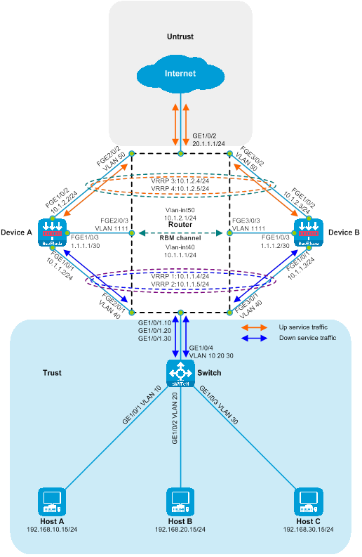
|
Device |
Interface |
IP Address |
Device |
Interface |
IP address |
|
Host A |
N/A |
192.168.10.15/24 |
Device A |
|
10.1.1.2/24 |
|
Host B |
N/A |
192.168.20.15/24 |
|
|
10.1.2.2/24 |
|
Host C |
N/A |
192.168.30.15/24 |
|
|
1.1.1.1/30 |
|
Router |
|
192.168.10.1/24 |
Device B |
|
10.1.1.3/24 |
|
|
GE1/0/1.20 |
192.168.20.1/24 |
|
|
10.1.2.3/24 |
|
|
GE1/0/1.30 |
192.168.30.1/24 |
|
The FGE1/0/3. |
1.1.1.2/30 |
|
|
GE1/0/2 |
20.1.1.1/24 |
|
|
|
|
|
Vlan-interface40 |
10.1.1.1/24 |
|
|
|
|
|
Vlan-interface50 |
10.1.2.1/24 |
|
|
|
Procedures
Configure the Switch.
Create VLAN 10, VLAN 20, and VLAN 30, and add GigabitEthernet1/0/1, GigabitEthernet1/0/2, and GigabitEthernet1/0/3 to VLAN 10, VLAN 20, and VLAN 30 respectively.
<Switch> system-view
[Switch] vlan 10
[Switch-vlan10] port gigabitethernet 1/0/1
[Switch-vlan10] quit
[Switch] vlan 20
[Switch-vlan20] port gigabitethernet 1/0/2
[Switch-vlan20] quit
[Switch] vlan 30
[Switch-vlan30] port gigabitethernet 1/0/3
[Switch-vlan30] quit
Configure the link type of GigabitEthernet1/0/4 as Trunk, and allow packets from VLAN 10, VLAN 20, and VLAN 30 to pass.
[Switch] interface gigabitethernet 1/0/4
[Switch-GigabitEthernet1/0/4] port link-type trunk
[Switch-GigabitEthernet1/0/4] port trunk permit vlan 10 20 30
[Switch-GigabitEthernet1/0/4] quit
Configuring Router
Configure the IP for the GigabitEthernet1/0/2 interface.
<Router> system-view
[Router] interface gigabitethernet 1/0/2
[Router-GigabitEthernet1/0/2] ip address 20.1.1.1 24
[Router-GigabitEthernet1/0/2] quit
Create Layer 3 subinterfaces GigabitEthernet1/0/1.10, GigabitEthernet1/0/1.20, and GigabitEthernet1/0/1.30, turn on the Dot1q termination function, terminate VLAN 10, VLAN 20, and VLAN 30 respectively, and configure the interface IP.
[Router] interface gigabitethernet 1/0/1.10
[Router-GigabitEthernet1/0/1.10] vlan-type dot1q vid 10
[Router-GigabitEthernet1/0/1.10] ip address 192.168.10.1 24
[Router-GigabitEthernet1/0/1.10] quit
[Router] interface gigabitethernet 1/0/1.20
[Router-GigabitEthernet1/0/1.20] vlan-type dot1q vid 20
[Router-GigabitEthernet1/0/1.20] ip address 192.168.20.1 24
[Router-GigabitEthernet1/0/1.20] quit
[Router] interface gigabitethernet 1/0/1.30
[Router-GigabitEthernet1/0/1.30] vlan-type dot1q vid 30
[Router-GigabitEthernet1/0/1.30] ip address 192.168.30.1 24
[Router-GigabitEthernet1/0/1.30] quit
Switch the working modes of FortyGigE2/0/1, FortyGigE2/0/2, FortyGigE2/0/3, FortyGigE3/0/1, FortyGigE3/0/2, and FortyGigE3/0/3 to Layer 2 mode.
[Router] interface range fortygige 2/0/1 fortygige 2/0/2 fortygige 2/0/3 fortygige 3/0/1 fortygige 3/0/2 fortygige 3/0/3
[Router-if-range] port link-mode bridge
[Router-if-range] quit
Create VLAN 40, VLAN 50, and VLAN 1111. Add FortyGigE2/0/1 and FortyGigE3/0/1 to VLAN 40, FortyGigE2/0/2 and FortyGigE3/0/2 to VLAN 50, and FortyGigE2/0/3 and FortyGigE3/0/3 to VLAN 1111.
[Router] vlan 40
[Router-vlan40] port fortygige 2/0/1 fortygige 3/0/1
[Router-vlan40] quit
[Router] vlan 50
[Router-vlan50] port fortygige 2/0/2 fortygige 3/0/2
[Router-vlan50] quit
[Router] vlan 1111
[Router-vlan1111] port fortygige 2/0/3 fortygige 3/0/3
[Router-vlan1111] quit
Create VLAN 40 and VLAN 50 interfaces, configure interface IP, and enable forwarding with persistence to maintain the previous hop function.
[Router] interface vlan-interface 40
[Router-Vlan-interface40] ip address 10.1.1.1 24
[Router-Vlan-interface40] ip last-hop hold
[Router-Vlan-interface40] quit
[Router] interface vlan-interface 50
[Router-Vlan-interface50] ip address 10.1.2.1 24
[Router-Vlan-interface50] ip last-hop hold
[Router-Vlan-interface50] quit
Turn off the fast switch load sharing function to prevent Layer 3 loops.
[Router] undo ip fast-forwarding load-sharing
Create an IPv4 advanced ACL to match up and down traffic flow.
[Router] acl advanced 3001
[Router-acl-ipv4-adv-3001] rule permit ip source 192.168.10.0 0.0.0.255 destination 20.1.1.0 0.0.0.255
[Router-acl-ipv4-adv-3001] quit
[Router] acl advanced 3002
[Router-acl-ipv4-adv-3002] rule permit ip source 192.168.20.0 0.0.0.255 destination 20.1.1.0 0.0.0.255
[Router-acl-ipv4-adv-3002] quit
[Router] acl advanced 3003
[Router-acl-ipv4-adv-3003] rule permit ip source 192.168.30.0 0.0.0.255 destination 20.1.1.0 0.0.0.255
[Router-acl-ipv4-adv-3003] quit
[Router] acl advanced 3004
[Router-acl-ipv4-adv-3004] rule permit ip source 20.1.1.0 0.0.0.255 destination 192.168.10.0 0.0.0.255
[Router-acl-ipv4-adv-3004] rule permit ip source 20.1.1.0 0.0.0.255 destination 192.168.20.0 0.0.0.255
[Router-acl-ipv4-adv-3004] rule permit ip source 20.1.1.0 0.0.0.255 destination 192.168.30.0 0.0.0.255
[Router-acl-ipv4-adv-3004] quit
Configure policy routing and bind the policy routing to the interface.
[Router] policy-based-route vlan10out permit node 10
[Router-pbr-vlan10out-10] if-match acl 3001
[Router-pbr-vlan10out-10] apply next-hop 10.1.1.4 weight 1
[Router-pbr-vlan10out-10] apply next-hop 10.1.1.5 weight 1
[Router-pbr-vlan10out-10] apply loadshare next-hop
[Router-pbr-vlan10out-10] quit
[Router] policy-based-route vlan20out permit node 10
[Router-pbr-vlan20out-10] if-match acl 3002
[Router-pbr-vlan20out-10] apply next-hop 10.1.1.4 weight 1
[Router-pbr-vlan20out-10] apply next-hop 10.1.1.5 weight 1
[Router-pbr-vlan20out-10] apply loadshare next-hop
[Router-pbr-vlan20out-10] quit
[Router] policy-based-route vlan30out permit node 10
[Router-pbr-vlan30out-10] if-match acl 3003
[Router-pbr-vlan30out-10] apply next-hop 10.1.1.4 weight 1
[Router-pbr-vlan30out-10] apply next-hop 10.1.1.5 weight 1
[Router-pbr-vlan30out-10] apply loadshare next-hop
[Router-pbr-vlan30out-10] quit
[Router] policy-based-route internetin permit node 10
[Router-pbr-internetin-10] if-match acl 3004
[Router-pbr-internetin-10] apply next-hop 10.1.2.4 weight 1
[Router-pbr-internetin-10] apply next-hop 10.1.2.5 weight 1
[Router-pbr-internetin-10] apply loadshare next-hop
[Router-pbr-internetin-10] quit
[Router] interface gigabitethernet 1/0/1.10
[Router-GigabitEthernet1/0/1.10] ip policy-based-route vlan10out
[Router-GigabitEthernet1/0/1.10] quit
[Router] interface gigabitethernet 1/0/1.20
[Router-GigabitEthernet1/0/1.20] ip policy-based-route vlan20out
[Router-GigabitEthernet1/0/1.20] quit
[Router] interface gigabitethernet 1/0/1.30
[Router-GigabitEthernet1/0/1.30] ip policy-based-route vlan30out
[Router-GigabitEthernet1/0/1.30] quit
[Router] interface gigabitethernet 1/0/2
[Router-GigabitEthernet1/0/2] ip policy-based-route internetin
[Router-GigabitEthernet1/0/2] quit
Configure Device A
Configure the interface IPs for FortyGigE1/0/1, FortyGigE1/0/2, and FortyGigE1/0/3. Set up VRRP backup groups 1, 2, 3, and 4, and associate them with HA.
<DeviceA> system-view
[DeviceA] interface fortygige 1/0/1
[DeviceA-FortyGigE1/0/1] ip address 10.1.1.2 24
[DeviceA-FortyGigE1/0/1] vrrp vrid 1 virtual-ip 10.1.1.4 active
[DeviceA-FortyGigE1/0/1] vrrp vrid 2 virtual-ip 10.1.1.5 standby
[DeviceA-FortyGigE1/0/1] quit
[DeviceA] interface fortygige 1/0/2
[DeviceA-FortyGigE1/0/2] ip address 10.1.2.2 24
[DeviceA-FortyGigE1/0/2] vrrp vrid 3 virtual-ip 10.1.2.4 active
[DeviceA-FortyGigE1/0/2] vrrp vrid 4 virtual-ip 10.1.2.5 standby
[DeviceA-FortyGigE1/0/2] quit
[DeviceA] interface fortygige 1/0/3
[DeviceA-FortyGigE1/0/3] ip address 1.1.1.1 30
[DeviceA-FortyGigE1/0/3] quit
Add FortyGigE1/0/1 and FortyGigE1/0/2 to the security domains Trust and Untrust respectively.
[DeviceA] security-zone name trust
[DeviceA-security-zone-Trust] import interface fortygige 1/0/1
[DeviceA-security-zone-Trust] quit
[DeviceA] security-zone name untrust
[DeviceA-security-zone-Untrust] import interface fortygige 1/0/2
[DeviceA-security-zone-Untrust] quit
Configure the security policy to allow inter-domain messages to pass.
[DeviceA] security-policy ip
[DeviceA-security-policy-ip] rule name trust-untrust
[DeviceA-security-policy-ip-0-trust-untrust] action pass
[DeviceA-security-policy-ip-0-trust-untrust] source-zone trust
[DeviceA-security-policy-ip-0-trust-untrust] destination-zone untrust
[DeviceA-security-policy-ip-0-trust-untrust] quit
[DeviceA-security-policy-ip] rule name untrust-trust
[DeviceA-security-policy-ip-1-untrust-trust] action pass
[DeviceA-security-policy-ip-1-untrust-trust] source-zone untrust
[DeviceA-security-policy-ip-1-untrust-trust] destination-zone trust
[DeviceA-security-policy-ip-1-untrust-trust] quit
[DeviceA-security-policy-ip] quit
The guide configures the static route to direct the upstream and downstream traffic forwarding.
[DeviceA] ip route-static 192.168.10.0 24 10.1.1.1
[DeviceA] ip route-static 192.168.20.0 24 10.1.1.1
[DeviceA] ip route-static 192.168.30.0 24 10.1.1.1
[DeviceA] ip route-static 20.1.1.0 24 10.1.2.1
Configure high availability (HA) RBM.
[DeviceA] remote-backup group
[DeviceA-remote-backup-group] remote-ip 1.1.1.2
[DeviceA-remote-backup-group] local-ip 1.1.1.1
[DeviceA-remote-backup-group] data-channel interface fortygige 1/0/3
[DeviceA-remote-backup-group] device-role primary
RBM_P[DeviceA-remote-backup-group] backup-mode dual-active
RBM_P[DeviceA-remote-backup-group] delay-time 1
RBM_P[DeviceA-remote-backup-group] quit
Configure Device B
Configure the IP interfaces for FortyGigE1/0/1, FortyGigE1/0/2, and FortyGigE1/0/3, set up VRRP backup groups 1, 2, 3, and 4, and associate them with HA.
<DeviceB> system-view
[DeviceB] interface fortygige 1/0/1
[DeviceB-FortyGigE1/0/1] ip address 10.1.1.3 24
[DeviceB-FortyGigE1/0/1] vrrp vrid 1 virtual-ip 10.1.1.4 standby
[DeviceB-FortyGigE1/0/1] vrrp vrid 2 virtual-ip 10.1.1.5 active
[DeviceB-FortyGigE1/0/1] quit
[DeviceB] interface fortygige 1/0/2
[DeviceB-FortyGigE1/0/2] ip address 10.1.2.3 24
[DeviceB-FortyGigE1/0/2] vrrp vrid 3 virtual-ip 10.1.2.4 standby
[DeviceB-FortyGigE1/0/2] vrrp vrid 4 virtual-ip 10.1.2.5 active
[DeviceB-FortyGigE1/0/2] quit
[DeviceB] interface fortygige 1/0/3
[DeviceB-FortyGigE1/0/3] ip address 1.1.1.2 30
[DeviceB-FortyGigE1/0/3] quit
Add FortyGigE1/0/1 and FortyGigE1/0/2 to the security domains Trust and Untrust, respectively.
[DeviceB] security-zone name trust
[DeviceB-security-zone-Trust] import interface fortygige 1/0/1
[DeviceB-security-zone-Trust] quit
[DeviceB] security-zone name untrust
[DeviceB-security-zone-Untrust] import interface fortygige 1/0/2
[DeviceB-security-zone-Untrust] quit
Configure the security policy to allow inter-domain messages to pass.
[DeviceB] security-policy ip
[DeviceB-security-policy-ip] rule name trust-untrust
[DeviceB-security-policy-ip-0-trust-untrust] action pass
[DeviceB-security-policy-ip-0-trust-untrust] source-zone trust
[DeviceB-security-policy-ip-0-trust-untrust] destination-zone untrust
[DeviceB-security-policy-ip-0-trust-untrust] quit
[DeviceB-security-policy-ip] rule name untrust-trust
[DeviceB-security-policy-ip-1-untrust-trust] action pass
[DeviceB-security-policy-ip-1-untrust-trust] source-zone untrust
[DeviceB-security-policy-ip-1-untrust-trust] destination-zone trust
[DeviceB-security-policy-ip-1-untrust-trust] quit
[DeviceB-security-policy-ip] quit
Guide for configuring static route to direct upstream and downstream traffic forwarding.
[DeviceB] ip route-static 192.168.10.0 24 10.1.1.1
[DeviceB] ip route-static 192.168.20.0 24 10.1.1.1
[DeviceB] ip route-static 192.168.30.0 24 10.1.1.1
[DeviceB] ip route-static 20.1.1.0 24 10.1.2.1
Configure the high availability (HA) RBM.
[DeviceB] remote-backup group
[DeviceB-remote-backup-group] remote-ip 1.1.1.1
[DeviceB-remote-backup-group] local-ip 1.1.1.2
[DeviceB-remote-backup-group] data-channel interface fortygige 1/0/3
[DeviceB-remote-backup-group] device-role secondary
RBM_S[DeviceB-remote-backup-group] backup-mode dual-active
RBM_S[DeviceB-remote-backup-group] delay-time 1
RBM_S[DeviceB-remote-backup-group] quit
Verifying the configuration
On Device A, execute the following display command to check if the HA configuration is effective and whether the HA channel is established.
RBM_P[DeviceA] display remote-backup-group status
Remote backup group information:
Backup mode: Dual-active
Device management role: Primary
Device running status: Active
Data channel interface: FortyGigE1/0/3
Local IP: 1.1.1.1
Remote IP: 1.1.1.2 Destination port: 60064
Control channel status: Connected
Keepalive interval: 1s
Keepalive count: 10
Configuration consistency check interval: 12 hour
Configuration consistency check result: Not Performed
Configuration backup status: Auto sync enabled
Session backup status: Hot backup enabled
Delay-time: 1 min
Uptime since last switchover: 0 days, 3 hours, 11 minutes
Switchover records:
Time Status change Cause
2021-06-22 13:33:33 Initial to Active Interface status changed
To view the status information of the VRRP backup group on Device A, execute the following display command.
RBM_P[DeviceA] display vrrp
IPv4 Virtual Router Information:
Running mode : Standard
RBM control channel is established
VRRP active group status : Master
VRRP standby group status: Backup
Total number of virtual routers : 2
Interface VRID State Running Adver Auth Virtual
Pri Timer Type IP
---------------------------------------------------------------------
FGE1/0/1 1 Master 100 100 None 10.1.1.4
FGE1/0/1 2 Backup 100 100 None 10.1.1.5
FGE1/0/2 3 Master 100 100 None 10.1.2.4
FGE1/0/2 4 Backup 100 100 None 10.1.2.5
# Execute the following display command on Device B to check whether the HA configuration is effective, and whether the HA channel is established.
RBM_S[DeviceB] display remote-backup-group status
Remote backup group information:
Backup mode: Dual-active
Device management role: Secondary
Device running status: Active
Data channel interface: FortyGigE1/0/3
Local IP: 1.1.1.2
Remote IP: 1.1.1.1 Destination port: 60064
Control channel status: Connected
Keepalive interval: 1s
Keepalive count: 10
Configuration consistency check interval: 12 hour
Configuration consistency check result: Not Performed
Configuration backup status: Auto sync enabled
Session backup status: Hot backup enabled
Delay-time: 1 min
Uptime since last switchover: 0 days, 3 hours, 12 minutes
Switchover records:
Time Status change Cause
2022-06-22 13:34:34 Initial to Active Interface status changed
On Device B, execute the following display command to view the state information of the VRRP backup group.
RBM_S[DeviceB] display vrrp
IPv4 Virtual Router Information:
Running mode : Standard
RBM control channel is established
VRRP active group status : Master
VRRP standby group status: Backup
Total number of virtual routers : 2
Interface VRID State Running Adver Auth Virtual
Pri Timer Type IP
---------------------------------------------------------------------
FGE1/0/1 1 Backup 100 100 None 10.1.1.4
FGE1/0/1 2 Master 100 100 None 10.1.1.5
FGE1/0/2 3 Backup 100 100 None 10.1.2.4
FGE1/0/2 4 Master 100 100 None 10.1.2.5
Host A is conducting a ping test on the Internet connectivity, and it can successfully ping the Internet address as 20.1.1.1.
C:\>ping 20.1.1.1
Pinging 20.1.1.1 with 32 bytes of data:
Reply from 20.1.1.1: bytes=32 time=3ms TTL=254
Reply from 20.1.1.1: bytes=32 time=2ms TTL=254
Reply from 20.1.1.1: bytes=32 time=1ms TTL=254
Reply from 20.1.1.1: bytes=32 time=2ms TTL=254
Ping statistics for 20.1.1.1:
Packets: Sent = 4, Received = 4, Lost = 0 (0% loss),
Approximate round trip times in milli-seconds:
Minimum = 1ms, Maximum = 3ms, Average = 2ms
Host B conducts a ping test on the Internet connectivity and can successfully ping the Internet address 20.1.1.1.
C:\>ping 20.1.1.1
Pinging 20.1.1.1 with 32 bytes of data:
Reply from 20.1.1.1: bytes=32 time=3ms TTL=254
Reply from 20.1.1.1: bytes=32 time=2ms TTL=254
Reply from 20.1.1.1: bytes=32 time=1ms TTL=254
Reply from 20.1.1.1: bytes=32 time=2ms TTL=254
Ping statistics for 20.1.1.1:
Packets: Sent = 4, Received = 4, Lost = 0 (0% loss),
Approximate round trip times in milli-seconds:
Minimum = 1ms, Maximum = 3ms, Average = 2ms
Host C tests the connectivity to the Internet by pinging, and it can reach the Internet address 20.1.1.1.
C:\>ping 20.1.1.1
Pinging 20.1.1.1 with 32 bytes of data:
Reply from 20.1.1.1: bytes=32 time=3ms TTL=254
Reply from 20.1.1.1: bytes=32 time=2ms TTL=254
Reply from 20.1.1.1: bytes=32 time=1ms TTL=254
Reply from 20.1.1.1: bytes=32 time=2ms TTL=254
Ping statistics for 20.1.1.1:
Packets: Sent = 4, Received = 4, Lost = 0 (0% loss),
Approximate round trip times in milli-seconds:
Minimum = 1ms, Maximum = 3ms, Average = 2ms
Check the session table on the device. There exists a session table between the host and 20.1.1.1.
RBM_P[DeviceA] display session table ipv4
Slot 1:
Initiator:
Source IP/port: 192.168.10.15/12005
Destination IP/port: 20.1.1.1/2048
DS-Lite tunnel peer: -
VPN instance/VLAN ID/Inline ID: -/-/-
Protocol: ICMP(1)
Inbound interface: FortyGigE1/0/1
Source security zone: Trust
Initiator:
Source IP/port: 192.168.20.15/12005
Destination IP/port: 20.1.1.1/2048
DS-Lite tunnel peer: -
VPN instance/VLAN ID/Inline ID: -/-/-
Protocol: ICMP(1)
Inbound interface: FortyGigE1/0/1
Source security zone: Trust
Initiator:
Source IP/port: 192.168.30.15/12005
Destination IP/port: 20.1.1.1/2048
DS-Lite tunnel peer: -
VPN instance/VLAN ID/Inline ID: -/-/-
Protocol: ICMP(1)
Inbound interface: FortyGigE1/0/1
Source security zone: Trust
Configuration file
Switch
#
vlan 10
#
vlan 20
#
vlan 30
#
interface GigabitEthernet1/0/1
port access vlan 10
#
interface GigabitEthernet1/0/2
port access vlan 20
#
interface GigabitEthernet1/0/3
port access vlan 30
#
interface GigabitEthernet1/0/4
port link-type trunk
port trunk permit vlan 10 20 30
#
Router
#
undo ip fast-forwarding load-sharing
#
vlan 40
#
vlan 50
#
vlan 1111
#
policy-based-route internetin permit node 10
if-match acl 3004
apply loadshare next-hold
apply next-hop 10.1.2.4 weight 1
apply next-hop 10.1.2.5 weight 1
#
policy-based-route vlan10out permit node 10
if-match acl 3001
apply loadshare next-hold
apply next-hop 10.1.1.4 weight 1
apply next-hop 10.1.1.5 weight 1
#
policy-based-route vlan20out permit node 10
if-match acl 3002
apply loadshare next-hold
apply next-hop 10.1.1.4 weight 1
apply next-hop 10.1.1.5 weight 1
#
policy-based-route vlan30out permit node 10
if-match acl 3003
apply loadshare next-hold
apply next-hop 10.1.1.4 weight 1
apply next-hop 10.1.1.5 weight 1
#
interface Vlan-interface40
ip address 10.1.1.1 255.255.255.0
ip last-hop hold
#
interface Vlan-interface50
ip address 10.1.2.1 255.255.255.0
ip last-hop hold
#
interface GigabitEthernet1/0/1.10
ip address 192.168.10.1 255.255.255.0
vlan-type dot1q vid 10
ip policy-based-route vlan10out
#
interface GigabitEthernet1/0/1.20
ip address 192.168.20.1 255.255.255.0
vlan-type dot1q vid 20
ip policy-based-route vlan20out
#
interface GigabitEthernet1/0/1.30
ip address 192.168.30.1 255.255.255.0
vlan-type dot1q vid 30
ip policy-based-route vlan30out
#
interface GigabitEthernet1/0/2
ip address 20.1.1.1 255.255.255.0
ip policy-based-route internetin
#
interface FortyGigE2/0/1
port link-mode bridge
port access vlan 40
#
interface FortyGigE2/0/2
port link-mode bridge
port access vlan 50
#
interface FortyGigE2/0/3
port link-mode bridge
port access vlan 1111
#
interface FortyGigE3/0/1
port link-mode bridge
port access vlan 40
#
interface FortyGigE3/0/2
port link-mode bridge
port access vlan 50
#
interface FortyGigE3/0/3
port link-mode bridge
port access vlan 1111
#
acl advanced 3001
rule 0 permit ip source 192.168.10.0 0.0.0.255 destination 20.1.1.0 0.0.0.255
#
acl advanced 3002
rule 0 permit ip source 192.168.20.0 0.0.0.255 destination 20.1.1.0 0.0.0.255
#
acl advanced 3003
rule 0 permit ip source 192.168.30.0 0.0.0.255 destination 20.1.1.0 0.0.0.255
#
acl advanced 3004
rule 0 permit ip source 20.1.1.0 0.0.0.255 destination 192.168.10.0 0.0.0.255
rule 5 permit ip source 20.1.1.0 0.0.0.255 destination 192.168.20.0 0.0.0.255
rule 10 permit ip source 20.1.1.0 0.0.0.255 destination 192.168.30.0 0.0.0.255
#
Device A
#
interface FortyGigE1/0/1
ip address 10.1.1.2 255.255.255.0
vrrp vrid 1 virtual-ip 10.1.1.4 active
vrrp vrid 2 virtual-ip 10.1.1.5 standby
#
interface FortyGigE1/0/2
ip address 10.1.2.2 255.255.255.0
vrrp vrid 3 virtual-ip 10.1.2.4 active
vrrp vrid 4 virtual-ip 10.1.2.5 standby
#
interface FortyGigE1/0/3
ip address 1.1.1.1 255.255.255.252
#
security-zone name Trust
import interface FortyGigE1/0/1
#
security-zone name Untrust
import interface FortyGigE1/0/2
#
ip route-static 20.1.1.0 24 10.1.2.1
ip route-static 192.168.10.0 24 10.1.1.1
ip route-static 192.168.20.0 24 10.1.1.1
ip route-static 192.168.30.0 24 10.1.1.1
#
security-policy ip
rule 0 name trust-untrust
action pass
source-zone trust
destination-zone untrust
rule 1 name untrust-trust
action pass
source-zone untrust
destination-zone trust
#
remote-backup group
backup-mode dual-active
data-channel interface FortyGigE1/0/3
delay-time 1
local-ip 1.1.1.1
remote-ip 1.1.1.2
device-role primary
#
Device B
#
interface FortyGigE1/0/1
ip address 10.1.1.3 255.255.255.0
vrrp vrid 1 virtual-ip 10.1.1.4 standby
vrrp vrid 2 virtual-ip 10.1.1.5 active
#
interface FortyGigE1/0/2
ip address 10.1.2.3 255.255.255.0
vrrp vrid 3 virtual-ip 10.1.2.4 standby
vrrp vrid 4 virtual-ip 10.1.2.5 active
#
interface FortyGigE1/0/3
ip address 1.1.1.2 255.255.255.252
#
security-zone name Trust
import interface FortyGigE1/0/1
#
security-zone name Untrust
import interface FortyGigE1/0/2
#
ip route-static 20.1.1.0 24 10.1.2.1
ip route-static 192.168.10.0 24 10.1.1.1
ip route-static 192.168.20.0 24 10.1.1.1
ip route-static 192.168.30.0 24 10.1.1.1
#
security-policy ip
rule 0 name trust-untrust
action pass
source-zone trust
destination-zone untrust
rule 1 name untrust-trust
action pass
source-zone untrust
destination-zone trust
#
remote-backup group
backup-mode dual-active
data-channel interface FortyGigE1/0/3
delay-time 1
local-ip 1.1.1.2
remote-ip 1.1.1.1
device-role secondary
#
Layer 3 direct route dual-master deployment of SecBlade module (partitioning VRF)
Network configuration
Host A, Host B, and Host C communicate with the Internet through a switch named Switch, and a router named Router. For security reasons, two SecBlade modules, Device A and Device B, need to be installed on the Router to provide security protection. The application requirements are as follows:
· Switch assigns Host A, Host B, and Host C to VLAN 10, VLAN 20, and VLAN 30 respectively, and transparently transmits traffic between the hosts and the internet.
· The router interfaces with the Host, Internet, and Device across three levels. The downstream port and Vlan-interface40 are delegated to VPN host, while the upstream port and Vlan-interface50 are assigned to VPN internet. Refer to the static route table to manage traffic between the Host and the Internet.
· Device connects to Router at Layer 3, checks the static routing table to forward traffic between Host and Internet, and Device A and Device B function as dual primary backups.
Figure 39 Network diagram of SecBlade module deployment with dual-master Layer 3 direct routing (VRF division).
Figure 40 Layer 3 straight routing dual-master deployment of SecBlade module (divided VRF) logical network diagram.
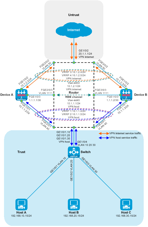
|
Device |
Interface |
IP address |
Device |
Interface |
IP Address |
|
Host A |
N/A |
192.168.10.15/24 |
Device A |
FGE1/0/1 |
10.1.1.2/30 |
|
Host B |
N/A |
192.168.20.15/24 |
|
FGE1/0/2 |
10.1.2.2/30 |
|
Host C |
N/A |
192.168.30.15/24 |
|
FGE1/0/3 |
1.1.1.1/30 |
|
Router |
GE1/0/1.10 |
192.168.10.1/24 |
Device B |
FGE1/0/1 |
10.1.1.3/30 |
|
|
|
192.168.20.1/24 |
|
FGE1/0/2 |
10.1.2.3/30 |
|
|
GE1/0/1.30 |
192.168.30.1/24 |
|
FGE1/0/3 |
1.1.1.2/30 |
|
|
Vlan-interface40 |
10.1.1.1/24 |
|
|
|
|
|
Vlan-interface50 |
10.1.2.1/24 |
|
|
|
|
|
GE1/0/2 |
20.1.1.1/24 |
|
|
|
Procedures
Configure the Switch.
Create VLAN 10, VLAN 20, and VLAN 30, and then add GigabitEthernet1/0/1, GigabitEthernet1/0/2, and GigabitEthernet1/0/3 to VLAN 10, VLAN 20, and VLAN 30 respectively.
<Switch> system-view
[Switch] vlan 10
[Switch-vlan10] port gigabitethernet 1/0/1
[Switch-vlan10] quit
[Switch] vlan 20
[Switch-vlan20] port gigabitethernet 1/0/2
[Switch-vlan20] quit
[Switch] vlan 30
[Switch-vlan30] port gigabitethernet 1/0/3
[Switch-vlan30] quit
Configure the link type of GigabitEthernet1/0/4 to Trunk and allow packets from VLAN 10, VLAN 20, and VLAN 30 to pass through.
[SwitchA] interface gigabitethernet 1/0/4
[SwitchA-GigabitEthernet1/0/4] port link-type trunk
[SwitchA-GigabitEthernet1/0/4] port trunk permit vlan 10 20 30
[SwitchA-GigabitEthernet1/0/4] quit
Configure the Router
Create a VPN-instance for host and internet.
[Router] ip vpn-instance host
[Router-vpn-instance-host] quit
[Router] ip vpn-instance internet
[Router-vpn-instance-internet] quit
Switch the working mode to layer 2 for these interfaces: FortyGigE2/0/1, FortyGigE2/0/2, FortyGigE2/0/3, FortyGigE3/0/1, FortyGigE3/0/2 and FortyGigE3/0/3.
[Router] interface range fortygige 2/0/1 fortygige 2/0/2 fortygige 2/0/3 fortygige 3/0/1 fortygige 3/0/2 fortygige 3/0/3
[Router-if-range] port link-mode bridge
[Router-if-range] quit
Create VLAN 40, VLAN 50, and VLAN 1111. Add FortyGigE2/0/1, FortyGigE3/0/1 to VLAN 40, add FortyGigE2/0/2, FortyGigE3/0/2 to VLAN 50, and add FortyGigE2/0/3, FortyGigE3/0/3 to VLAN 1111.
[Router] vlan 40
[Router-vlan40] port fortygige 2/0/1 fortygige 3/0/1
[Router-vlan40] quit
[Router] vlan 50
[Router-vlan50] port fortygige 2/0/2 fortygige 3/0/2
[Router-vlan50] quit
[Router] vlan 1111
[Router-vlan1111] port fortygige 2/0/3 fortygige 3/0/3
[Router-vlan1111] quit
Create VLAN 40 and VLAN 50 interfaces, bind them to a VPN instance, and configure the IP address of VLAN interfaces. Activate the function of forwarding persistence to the previous hop.
[Router] interface vlan-interface 40
[Router-Vlan-interface40] ip binding vpn-instance host
[Router-Vlan-interface40] ip address 10.1.1.1 24
[Router-Vlan-interface40] ip last-hop hold
[Router-Vlan-interface40] quit
[Router] interface vlan-interface 50
[Router-Vlan-interface50] ip binding vpn-instance internet
[Router-Vlan-interface50] ip address 10.1.2.1 24
[Router-Vlan-interface50] ip last-hop hold
[Router-Vlan-interface50] quit
Create three Layer 3 subinterfaces GigabitEthernet1/0/1.10, GigabitEthernet1/0/1.20, and GigabitEthernet1/0/1.30, enable Dot1q termination function, terminate VLAN 10, VLAN 20, and VLAN 30 respectively, bind VPN instance, and configure interface IP.
[Router] interface gigabitethernet 1/0/1.10
[Router-GigabitEthernet1/0/1.10] vlan-type dot1q vid 10
[Router-GigabitEthernet1/0/1.10] ip binding vpn-instance host
[Router-GigabitEthernet1/0/1.10] ip address 192.168.10.1 24
[Router-GigabitEthernet1/0/1.10] quit
[Router] interface gigabitethernet 1/0/1.20
[Router-GigabitEthernet1/0/1.20] vlan-type dot1q vid 20
[Router-GigabitEthernet1/0/1.20] ip binding vpn-instance host
[Router-GigabitEthernet1/0/1.20] ip address 192.168.20.1 24
[Router-GigabitEthernet1/0/1.20] quit
[Router] interface gigabitethernet 1/0/1.30
[Router-GigabitEthernet1/0/1.30] vlan-type dot1q vid 30
[Router-GigabitEthernet1/0/1.30] ip binding vpn-instance host
[Router-GigabitEthernet1/0/1.30] ip address 192.168.30.1 24
[Router-GigabitEthernet1/0/1.30] quit
Configure the IP of GigabitEthernet1/0/2 interface and bind it to the VPN instance.
[Router] interface gigabitethernet 1/0/2
[Router-GigabitEthernet1/0/2] ip binding vpn-instance internet
[Router-GigabitEthernet1/0/2] ip address 20.1.1.1 24
[Router-GigabitEthernet1/0/2] quit
Configure equivalent static routes to guide upstream and downstream traffic forwarding.
[Router] ip route-static vpn-instance host 20.1.1.0 24 vpn-instance host 10.1.1.4
[Router] ip route-static vpn-instance host 20.1.1.0 24 vpn-instance host 10.1.1.5
[Router] ip route-static vpn-instance internet 192.168.10.0 24 vpn-instance internet 10.1.2.4
[Router] ip route-static vpn-instance internet 192.168.20.0 24 vpn-instance internet 10.1.2.4
[Router] ip route-static vpn-instance internet 192.168.30.0 24 vpn-instance internet 10.1.2.4
[Router] ip route-static vpn-instance internet 192.168.10.0 24 vpn-instance internet 10.1.2.5
[Router] ip route-static vpn-instance internet 192.168.20.0 24 vpn-instance internet 10.1.2.5
[Router] ip route-static vpn-instance internet 192.168.30.0 24 vpn-instance internet 10.1.2.5
Configure Device A
Configure the interface IPs of FortyGigE1/0/1, FortyGigE1/0/2 and FortyGigE1/0/3, set up VRRP backup groups 1, 2, 3, and 4, and associate them with HA.
<DeviceA> system-view
[DeviceA] interface fortygige 1/0/1
[DeviceA-FortyGigE1/0/1] ip address 10.1.1.2 24
[DeviceA-FortyGigE1/0/1] vrrp vrid 1 virtual-ip 10.1.1.4 active
[DeviceA-FortyGigE1/0/1] vrrp vrid 2 virtual-ip 10.1.1.5 standby
[DeviceA-FortyGigE1/0/1] quit
[DeviceA] interface fortygige 1/0/2
[DeviceA-FortyGigE1/0/2] ip address 10.1.2.2 24
[DeviceA-FortyGigE1/0/2] vrrp vrid 3 virtual-ip 10.1.2.4 active
[DeviceA-FortyGigE1/0/2] vrrp vrid 4 virtual-ip 10.1.2.5 standby
[DeviceA-FortyGigE1/0/2] quit
[DeviceA] interface fortygige 1/0/3
[DeviceA-FortyGigE1/0/3] ip address 1.1.1.1 30
[DeviceA-FortyGigE1/0/3] quit
Add FortyGigE1/0/1 and FortyGigE1/0/2 respectively to the security domains Trust and Untrust.
[DeviceA] security-zone name trust
[DeviceA-security-zone-Trust] import interface fortygige 1/0/1
[DeviceA-security-zone-Trust] quit
[DeviceA] security-zone name untrust
[DeviceA-security-zone-Untrust] import interface fortygige 1/0/2
[DeviceA-security-zone-Untrust] quit
Configure the security policy to allow messages to pass between domains.
[DeviceA] security-policy ip
[DeviceA-security-policy-ip] rule name trust-untrust
[DeviceA-security-policy-ip-0-trust-untrust] action pass
[DeviceA-security-policy-ip-0-trust-untrust] source-zone trust
[DeviceA-security-policy-ip-0-trust-untrust] destination-zone untrust
[DeviceA-security-policy-ip-0-trust-untrust] quit
[DeviceA-security-policy-ip] rule name untrust-trust
[DeviceA-security-policy-ip-1-untrust-trust] action pass
[DeviceA-security-policy-ip-1-untrust-trust] source-zone untrust
[DeviceA-security-policy-ip-1-untrust-trust] destination-zone trust
[DeviceA-security-policy-ip-1-untrust-trust] quit
[DeviceA-security-policy-ip] quit
Configure the static route to guide the traffic forwarding of upstream and downstream.
[DeviceA] ip route-static 192.168.10.0 24 10.1.1.1
[DeviceA] ip route-static 192.168.20.0 24 10.1.1.1
[DeviceA] ip route-static 192.168.30.0 24 10.1.1.1
[DeviceA] ip route-static 20.1.1.0 24 10.1.2.1
Configure high availability (HA) RBM.
[DeviceA] remote-backup group
[DeviceA-remote-backup-group] remote-ip 1.1.1.2
[DeviceA-remote-backup-group] local-ip 1.1.1.1
[DeviceA-remote-backup-group] data-channel interface fortygige 1/0/3
[DeviceA-remote-backup-group] device-role primary
RBM_P[DeviceA-remote-backup-group] backup-mode dual-active
RBM_P[DeviceA-remote-backup-group] delay-time 1
RBM_P[DeviceA-remote-backup-group] quit
Configure Device B
Configure the interface IP for FortyGigE1/0/1, FortyGigE1/0/2, and FortyGigE1/0/3. Set up VRRP backup groups 1, 2, 3, and 4 and associate them with HA.
<DeviceB> system-view
[DeviceB] interface fortygige 1/0/1
[DeviceB-FortyGigE1/0/1] ip address 10.1.1.3 24
[DeviceB-FortyGigE1/0/1] vrrp vrid 1 virtual-ip 10.1.1.4 standby
[DeviceB-FortyGigE1/0/1] vrrp vrid 2 virtual-ip 10.1.1.5 active
[DeviceB-FortyGigE1/0/1] quit
[DeviceB] interface fortygige 1/0/2
[DeviceB-FortyGigE1/0/2] ip address 10.1.2.3 24
[DeviceB-FortyGigE1/0/2] vrrp vrid 3 virtual-ip 10.1.2.4 standby
[DeviceB-FortyGigE1/0/2] vrrp vrid 4 virtual-ip 10.1.2.5 active
[DeviceB-FortyGigE1/0/2] quit
[DeviceB] interface fortygige 1/0/3
[DeviceB-FortyGigE1/0/3] ip address 1.1.1.2 30
[DeviceB-FortyGigE1/0/3] quit
Add FortyGigE1/0/1 and FortyGigE1/0/2 to the security domains Trust and Untrust, respectively.
[DeviceB] security-zone name trust
[DeviceB-security-zone-Trust] import interface fortygige 1/0/1
[DeviceB-security-zone-Trust] quit
[DeviceB] security-zone name untrust
[DeviceB-security-zone-Untrust] import interface fortygige 1/0/2
[DeviceB-security-zone-Untrust] quit
Configure the security policy to allow inter-domain messages to pass.
[DeviceB] security-policy ip
[DeviceB-security-policy-ip] rule name trust-untrust
[DeviceB-security-policy-ip-0-trust-untrust] action pass
[DeviceB-security-policy-ip-0-trust-untrust] source-zone trust
[DeviceB-security-policy-ip-0-trust-untrust] destination-zone untrust
[DeviceB-security-policy-ip-0-trust-untrust] quit
[DeviceB-security-policy-ip] rule name untrust-trust
[DeviceB-security-policy-ip-1-untrust-trust] action pass
[DeviceB-security-policy-ip-1-untrust-trust] source-zone untrust
[DeviceB-security-policy-ip-1-untrust-trust] destination-zone trust
[DeviceB-security-policy-ip-1-untrust-trust] quit
[DeviceB-security-policy-ip] quit
Configure static route guidance to direct upstream and downstream traffic forwarding.
[DeviceB] ip route-static 192.168.10.0 24 10.1.1.1
[DeviceB] ip route-static 192.168.20.0 24 10.1.1.1
[DeviceB] ip route-static 192.168.30.0 24 10.1.1.1
[DeviceB] ip route-static 20.1.1.0 24 10.1.2.1
Configure high availability (HA) RBM.
[DeviceB] remote-backup group
[DeviceB-remote-backup-group] remote-ip 1.1.1.1
[DeviceB-remote-backup-group] local-ip 1.1.1.2
[DeviceB-remote-backup-group] data-channel interface fortygige 1/0/3
[DeviceB-remote-backup-group] device-role secondary
RBM_S[DeviceB-remote-backup-group] backup-mode dual-active
RBM_S[DeviceB-remote-backup-group] delay-time 1
RBM_S[DeviceB-remote-backup-group] quit
Verifying the configuration
To check if the HA configuration is effective and if the HA channel has been established, execute the following display command on Device A.
RBM_P[DeviceA] display remote-backup-group status
Remote backup group information:
Backup mode: Dual-active
Device management role: Primary
Device running status: Active
Data channel interface: FortyGigE1/0/3
Local IP: 1.1.1.1
Remote IP: 1.1.1.2 Destination port: 60064
Control channel status: Connected
Keepalive interval: 1s
Keepalive count: 10
Configuration consistency check interval: 12 hour
Configuration consistency check result: Not Performed
Configuration backup status: Auto sync enabled
Session backup status: Hot backup enabled
Delay-time: 1 min
Uptime since last switchover: 0 days, 3 hours, 11 minutes
Switchover records:
Time Status change Cause
2021-06-22 13:33:33 Initial to Active Interface status changed
Execute the following display command on Device A to check the status information of the VRRP backup group.
RBM_P[DeviceA] display vrrp
IPv4 Virtual Router Information:
Running mode : Standard
RBM control channel is established
VRRP active group status : Master
VRRP standby group status: Backup
Total number of virtual routers : 2
Interface VRID State Running Adver Auth Virtual
Pri Timer Type IP
---------------------------------------------------------------------
FGE1/0/1 1 Master 100 100 None 10.1.1.4
FGE1/0/1 2 Backup 100 100 None 10.1.1.5
FGE1/0/2 3 Master 100 100 None 10.1.2.4
FGE1/0/2 4 Backup 100 100 None 10.1.2.5
# Execute the following display command on Device B to verify if the HA configuration is effective, and whether the HA channel is established.
RBM_S[DeviceB] display remote-backup-group status
Remote backup group information:
Backup mode: Dual-active
Device management role: Secondary
Device running status: Active
Data channel interface: FortyGigE1/0/3
Local IP: 1.1.1.2
Remote IP: 1.1.1.1 Destination port: 60064
Control channel status: Connected
Keepalive interval: 1s
Keepalive count: 10
Configuration consistency check interval: 12 hour
Configuration consistency check result: Not Performed
Configuration backup status: Auto sync enabled
Session backup status: Hot backup enabled
Delay-time: 1 min
Uptime since last switchover: 0 days, 3 hours, 12 minutes
Switchover records:
Time Status change Cause
2022-06-22 13:34:34 Initial to Active Interface status changed
On Device B, execute the following display command to view the state information of the VRRP backup group.
RBM_S[DeviceB] display vrrp
IPv4 Virtual Router Information:
Running mode : Standard
RBM control channel is established
VRRP active group status : Master
VRRP standby group status: Backup
Total number of virtual routers : 2
Interface VRID State Running Adver Auth Virtual
Pri Timer Type IP
---------------------------------------------------------------------
FGE1/0/1 1 Backup 100 100 None 10.1.1.4
FGE1/0/1 2 Master 100 100 None 10.1.1.5
FGE1/0/2 3 Backup 100 100 None 10.1.2.4
FGE1/0/2 4 Master 100 100 None 10.1.2.5
"Host A pings the Internet to test connectivity, and it can successfully ping the Internet address 20.1.1.1."
C:\>ping 20.1.1.1
Pinging 20.1.1.1 with 32 bytes of data:
Reply from 20.1.1.1: bytes=32 time=3ms TTL=254
Reply from 20.1.1.1: bytes=32 time=2ms TTL=254
Reply from 20.1.1.1: bytes=32 time=1ms TTL=254
Reply from 20.1.1.1: bytes=32 time=2ms TTL=254
Ping statistics for 20.1.1.1:
Packets: Sent = 4, Received = 4, Lost = 0 (0% loss),
Approximate round trip times in milli-seconds:
Minimum = 1ms, Maximum = 3ms, Average = 2ms
On Host B, perform a ping test to check the connectivity to the Internet. You should be able to ping the Internet address 20.1.1.1.
C:\>ping 20.1.1.1
Pinging 20.1.1.1 with 32 bytes of data:
Reply from 20.1.1.1: bytes=32 time=3ms TTL=254
Reply from 20.1.1.1: bytes=32 time=2ms TTL=254
Reply from 20.1.1.1: bytes=32 time=1ms TTL=254
Reply from 20.1.1.1: bytes=32 time=2ms TTL=254
Ping statistics for 20.1.1.1:
Packets: Sent = 4, Received = 4, Lost = 0 (0% loss),
Approximate round trip times in milli-seconds:
Minimum = 1ms, Maximum = 3ms, Average = 2ms
Host C is testing the connectivity to the
Internet by pinging, and it successfully pings the Internet address 20.1.1.1.
C:\>ping 20.1.1.1
Pinging 20.1.1.1 with 32 bytes of data:
Reply from 20.1.1.1: bytes=32 time=3ms TTL=254
Reply from 20.1.1.1: bytes=32 time=2ms TTL=254
Reply from 20.1.1.1: bytes=32 time=1ms TTL=254
Reply from 20.1.1.1: bytes=32 time=2ms TTL=254
Ping statistics for 20.1.1.1:
Packets: Sent = 4, Received = 4, Lost = 0 (0% loss),
Approximate round trip times in milli-seconds:
Minimum = 1ms, Maximum = 3ms, Average = 2ms
Check the session table on the device, there exists a session table between the host and 20.1.1.1.
RBM_P[DeviceA] display session table ipv4
Slot 1:
Initiator:
Source IP/port: 192.168.10.15/12005
Destination IP/port: 20.1.1.1/2048
DS-Lite tunnel peer: -
VPN instance/VLAN ID/Inline ID: -/-/-
Protocol: ICMP(1)
Inbound interface: FortyGigE1/0/1
Source security zone: Trust
Initiator:
Source IP/port: 192.168.20.15/12005
Destination IP/port: 20.1.1.1/2048
DS-Lite tunnel peer: -
VPN instance/VLAN ID/Inline ID: -/-/-
Protocol: ICMP(1)
Inbound interface: FortyGigE1/0/1
Source security zone: Trust
Initiator:
Source IP/port: 192.168.30.15/12005
Destination IP/port: 20.1.1.1/2048
DS-Lite tunnel peer: -
VPN instance/VLAN ID/Inline ID: -/-/-
Protocol: ICMP(1)
Inbound interface: FortyGigE1/0/1
Source security zone: Trust
Configuration File
Switch
#
vlan 10
#
vlan 20
#
vlan 30
#
interface GigabitEthernet1/0/1
port access vlan 10
#
interface GigabitEthernet1/0/2
port access vlan 20
#
interface GigabitEthernet1/0/3
port access vlan 30
#
interface GigabitEthernet1/0/4
port link-type trunk
port trunk permit vlan 10 20 30
#
Router
#
ip vpn-instance host
#
ip vpn-instance internet
#
vlan 40
#
vlan 50
#
vlan 1111
#
interface Vlan-interface40
ip binding vpn-instance host
ip address 10.1.1.1 255.255.255.0
ip last-hop hold
#
interface Vlan-interface50
ip binding vpn-instance internet
ip address 10.1.2.1 255.255.255.0
ip last-hop hold
#
interface GigabitEthernet1/0/1.10
ip binding vpn-instance host
ip address 192.168.10.1 255.255.255.0
vlan-type dot1q vid 10
#
interface GigabitEthernet1/0/1.20
ip binding vpn-instance host
ip address 192.168.20.1 255.255.255.0
vlan-type dot1q vid 20
#
interface GigabitEthernet1/0/1.30
ip binding vpn-instance host
ip address 192.168.30.1 255.255.255.0
vlan-type dot1q vid 30
#
interface GigabitEthernet1/0/2
ip binding vpn-instance internet
ip address 20.1.1.1 255.255.255.0
#
interface FortyGige2/0/1
port link-mode bridge
port access vlan 40
#
interface FortyGige2/0/2
port link-mode bridge
port access vlan 50
#
interface FortyGige2/0/3
port link-mode bridge
port access vlan 1111
#
interface FortyGige3/0/1
port link-mode bridge
port access vlan 40
#
interface FortyGige3/0/2
port link-mode bridge
port access vlan 50
#
interface FortyGige3/0/3
port link-mode bridge
port access vlan 1111
#
ip route-static vpn-instance host 20.1.1.0 24 10.1.1.4
ip route-static vpn-instance host 20.1.1.0 24 10.1.1.5
ip route-static vpn-instance internet 192.168.10.0 24 10.1.2.4
ip route-static vpn-instance internet 192.168.20.0 24 10.1.2.4
ip route-static vpn-instance internet 192.168.30.0 24 10.1.2.4
ip route-static vpn-instance internet 192.168.10.0 24 10.1.2.5
ip route-static vpn-instance internet 192.168.20.0 24 10.1.2.5
ip route-static vpn-instance internet 192.168.30.0 24 10.1.2.5
#
Device A
#
interface FortyGigE1/0/1
ip address 10.1.1.2 255.255.255.0
vrrp vrid 1 virtual-ip 10.1.1.4 active
vrrp vrid 2 virtual-ip 10.1.1.5 standby
#
interface FortyGigE1/0/2
ip address 10.1.2.2 255.255.255.0
vrrp vrid 3 virtual-ip 10.1.2.4 active
vrrp vrid 4 virtual-ip 10.1.2.5 standby
#
interface FortyGigE1/0/3
ip address 1.1.1.1 255.255.255.252
#
security-zone name Trust
import interface FortyGigE1/0/1
#
security-zone name Untrust
import interface FortyGigE1/0/2
#
ip route-static 20.1.1.0 24 10.1.2.1
ip route-static 192.168.10.0 24 10.1.1.1
ip route-static 192.168.20.0 24 10.1.1.1
ip route-static 192.168.30.0 24 10.1.1.1
#
security-policy ip
rule 0 name trust-untrust
action pass
source-zone trust
destination-zone untrust
rule 1 name untrust-trust
action pass
source-zone untrust
destination-zone trust
#
remote-backup group
backup-mode dual-active
data-channel interface FortyGigE1/0/3
delay-time 1
local-ip 1.1.1.1
remote-ip 1.1.1.2
device-role primary
#
Device B
#
interface FortyGigE1/0/1
ip address 10.1.1.3 255.255.255.0
vrrp vrid 1 virtual-ip 10.1.1.4 standby
vrrp vrid 2 virtual-ip 10.1.1.5 active
#
interface FortyGigE1/0/2
ip address 10.1.2.3 255.255.255.0
vrrp vrid 3 virtual-ip 10.1.2.4 standby
vrrp vrid 4 virtual-ip 10.1.2.5 active
#
interface FortyGigE1/0/3
ip address 1.1.1.2 255.255.255.252
#
security-zone name Trust
import interface FortyGigE1/0/1
#
security-zone name Untrust
import interface FortyGigE1/0/2
#
ip route-static 20.1.1.0 24 10.1.2.1
ip route-static 192.168.10.0 24 10.1.1.1
ip route-static 192.168.20.0 24 10.1.1.1
ip route-static 192.168.30.0 24 10.1.1.1
#
security-policy ip
rule 0 name trust-untrust
action pass
source-zone trust
destination-zone untrust
rule 1 name untrust-trust
action pass
source-zone untrust
destination-zone trust
#
remote-backup group
backup-mode dual-active
data-channel interface FortyGigE1/0/3
delay-time 1
local-ip 1.1.1.2
remote-ip 1.1.1.1
device-role secondary
#
SecBlade module deployment in a dual-primary manner on a Layer 3 direct path (dividing VLAN)
Network configuration requirement
Host A, Host B, and Host C communicate with the Internet via access router Router A, aggregation switch Switch and core router Router B. For security reasons, two SecBlade modules, Device A and Device B, need to be deployed on the aggregation switch Switch to serve as security defenses, with application requirements as follows:
· Router A serves as the gateway for Host A, Host B, and Host C, checking the static routing table to forward traffic from the hosts to the Internet.
· Switch allocates the downstream service ports to VLAN 40 and the upstream service ports to VLAN 50. The interconnection ports with the Device are assigned to both VLAN 40 and VLAN 50. The upstream and downstream traffic between the Host and the Internet is transparently transmitted to the Device.
· Device connects to Router A and Router B at Layer 3, checks the static route table to forward traffic between Host and the Internet, and Device A and Device B serve as dual primary backups.
· Router B interfaces with Device at Layer 3, it checks the static route table and forwards Internet traffic to the host.
Figure 41 The network diagram of the Layer 3ed direct path dual master deployment of a SecBlade module (dividing VLAN) group.
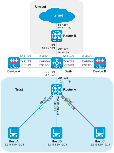
Figure 42 Layer 3 straight road dual master deployment of SecBlade module (partition VLAN) logical networking diagram.
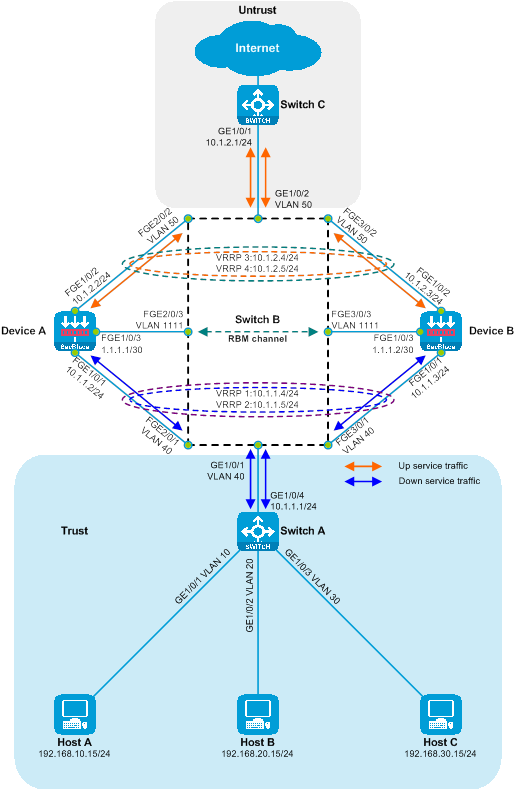
|
Device |
Interface |
IP address |
Device |
Interface |
IP address |
|
Host A |
N/A |
192.168.10.15/24 |
Device B |
FGE1/0/1 |
10.1.1.3/24 |
|
Host B |
N/A |
192.168.20.15/24 |
|
FGE1/0/2 |
10.1.2.3/24 |
|
Host C |
N/A |
192.168.30.15/24 |
|
|
1.1.1.2/30 |
|
Router A |
|
192.168.10.1/24 |
Router B |
GE1/0/1 |
10.1.2.1/24 |
|
|
GE1/0/2 |
192.168.20.1/24 |
|
|
20.1.1.1/24 |
|
|
GE1/0/3 |
192.168.30.1/24 |
|
|
|
|
|
GE1/0/4 |
10.1.1.1/24 |
|
|
|
|
Device A |
|
10.1.1.2/24 |
|
|
|
|
|
FGE1/0/2 |
10.1.2.2/24 |
|
|
|
|
|
FGE1/0/3 |
1.1.1.1/30 |
|
|
|
Procedures
Configure Router A.
Configure the IP of GigabitEthernet1/0/1, GigabitEthernet1/0/2, GigabitEthernet1/0/3, and GigabitEthernet1/0/4 interfaces. Turn on the forwarding persistence function of the next hop for GigabitEthernet1/0/4.
<RouterA> system-view
[RouterA] interface GigabitEthernet 1/0/1
[RouterA-GigabitEthernet1/0/1] ip address 192.168.10.1 24
[RouterA-GigabitEthernet1/0/1] quit
[RouterA] interface GigabitEthernet 1/0/2
[RouterA-GigabitEthernet1/0/2] ip address 192.168.20.1 24
[RouterA-GigabitEthernet1/0/2] quit
[RouterA] interface GigabitEthernet 1/0/3
[RouterA-GigabitEthernet1/0/3] ip address 192.168.30.1 24
[RouterA-GigabitEthernet1/0/3] quit
[RouterA] interface GigabitEthernet 1/0/4
[RouterA-GigabitEthernet1/0/4] ip address 10.1.1.1 24
[RouterA-GigabitEthernet1/0/4] ip last-hop hold
[RouterA-GigabitEthernet1/0/4] quit
Guide to configure equivalent static routing for upstream traffic forwarding.
[SwitchA] ip route-static 20.1.1.0 24 10.1.1.4
[SwitchA] ip route-static 20.1.1.0 24 10.1.1.5
Configure the Switch.
Create VLAN 40, VLAN 50 and VLAN 1111. Include GigabitEthernet1/0/1, FortyGigE2/0/1 and FortyGigE3/0/1 in VLAN 40. Include GigabitEthernet1/0/2, FortyGigE2/0/2 and FortyGigE3/0/2 in VLAN 50. Lastly, include FortyGigE2/0/3 and FortyGigE3/0/3 in VLAN 1111.
<Switch> system-view
[Switch] vlan 40
[Switch-vlan40] port GigabitEthernet 1/0/1 fortygige 2/0/1 fortygige 3/0/1
[Switch-vlan40] quit
[Switch] vlan 50
[Switch-vlan50] port GigabitEthernet 1/0/2 fortygige 2/0/2 fortygige 3/0/2
[Switch-vlan50] quit
[Switch] vlan 1111
[Switch-vlan1111] port fortygige 2/0/3 fortygige 3/0/3
[Switch-vlan1111] quit
Configure Router B.
Configure the IP of GigabitEthernet1/0/1 and GigabitEthernet1/0/2 interfaces, and enable the persistence of the previous hop function for GigabitEthernet1/0/1.
<RouterB> system-view
[RouterB] interface GigabitEthernet 1/0/1
[RouterB-GigabitEthernet1/0/1] ip address 10.1.2.1 24
[RouterB-GigabitEthernet1/0/1] ip last-hop hold
[RouterB-GigabitEthernet1/0/1] quit
[RouterB] interface GigabitEthernet 1/0/2
[RouterB-GigabitEthernet1/0/2] ip address 20.1.1.1 24
[RouterB-GigabitEthernet1/0/2] quit
Configure equivalent static routes to guide downstream traffic forwarding.
[RouterB] ip route-static 192.168.10.0 24 10.1.2.4
[RouterB] ip route-static 192.168.10.0 24 10.1.2.5
[RouterB] ip route-static 192.168.20.0 24 10.1.2.4
[RouterB] ip route-static 192.168.20.0 24 10.1.2.5
[RouterB] ip route-static 192.168.30.0 24 10.1.2.4
[RouterB] ip route-static 192.168.30.0 24 10.1.2.5
Configure Device A
Configure the interface IP for FortyGigE1/0/1, FortyGigE1/0/2, and FortyGigE1/0/3, set up VRRP backup groups 1, 2, 3, and 4, and associate them with HA.
<DeviceA> system-view
[DeviceA] interface fortygige 1/0/1
[DeviceA-FortyGigE1/0/1] ip address 10.1.1.2 24
[DeviceA-FortyGigE1/0/1] vrrp vrid 1 virtual-ip 10.1.1.4 active
[DeviceA-FortyGigE1/0/1] vrrp vrid 2 virtual-ip 10.1.1.5 standby
[DeviceA-FortyGigE1/0/1] quit
[DeviceA] interface fortygige 1/0/2
[DeviceA-FortyGigE1/0/2] ip address 10.1.2.2 24
[DeviceA-FortyGigE1/0/2] vrrp vrid 3 virtual-ip 10.1.2.4 active
[DeviceA-FortyGigE1/0/2] vrrp vrid 4 virtual-ip 10.1.2.5 standby
[DeviceA-FortyGigE1/0/2] quit
[DeviceA] interface fortygige 1/0/3
[DeviceA-FortyGigE1/0/3] ip address 1.1.1.1 30
[DeviceA-FortyGigE1/0/3] quit
Add FortyGigE1/0/1 and FortyGigE1/0/2 respectively to the security domains Trust and Untrust.
[DeviceA] security-zone name trust
[DeviceA-security-zone-Trust] import interface fortygige 1/0/1
[DeviceA-security-zone-Trust] quit
[DeviceA] security-zone name untrust
[DeviceA-security-zone-Untrust] import interface fortygige 1/0/2
[DeviceA-security-zone-Untrust] quit
Configure the security policy to allow inter-domain messages to pass.
[DeviceA] security-policy ip
[DeviceA-security-policy-ip] rule name trust-untrust
[DeviceA-security-policy-ip-0-trust-untrust] action pass
[DeviceA-security-policy-ip-0-trust-untrust] source-zone trust
[DeviceA-security-policy-ip-0-trust-untrust] destination-zone untrust
[DeviceA-security-policy-ip-0-trust-untrust] quit
[DeviceA-security-policy-ip] rule name untrust-trust
[DeviceA-security-policy-ip-1-untrust-trust] action pass
[DeviceA-security-policy-ip-1-untrust-trust] source-zone untrust
[DeviceA-security-policy-ip-1-untrust-trust] destination-zone trust
[DeviceA-security-policy-ip-1-untrust-trust] quit
[DeviceA-security-policy-ip] quit
Configure static routing to direct both upstream and downstream traffic forwarding.
[DeviceA] ip route-static 192.168.10.0 24 10.1.1.1
[DeviceA] ip route-static 192.168.20.0 24 10.1.1.1
[DeviceA] ip route-static 192.168.30.0 24 10.1.1.1
[DeviceA] ip route-static 20.1.1.0 24 10.1.2.1
Configure high availability (HA) RBM.
[DeviceA] remote-backup group
[DeviceA-remote-backup-group] remote-ip 1.1.1.2
[DeviceA-remote-backup-group] local-ip 1.1.1.1
[DeviceA-remote-backup-group] data-channel interface fortygige 1/0/3
[DeviceA-remote-backup-group] device-role primary
RBM_P[DeviceA-remote-backup-group] backup-mode dual-active
RBM_P[DeviceA-remote-backup-group] delay-time 1
RBM_P[DeviceA-remote-backup-group] quit
Configure Device B
Configure the interface IPs of FortyGigE1/0/1, FortyGigE1/0/2, and FortyGigE1/0/3, set up VRRP backup groups 1, 2, 3, and 4, and associate them with HA.
<DeviceB> system-view
[DeviceB] interface fortygige 1/0/1
[DeviceB-FortyGigE1/0/1] ip address 10.1.1.3 24
[DeviceB-FortyGigE1/0/1] vrrp vrid 1 virtual-ip 10.1.1.4 standby
[DeviceB-FortyGigE1/0/1] vrrp vrid 2 virtual-ip 10.1.1.5 active
[DeviceB-FortyGigE1/0/1] quit
[DeviceB] interface fortygige 1/0/2
[DeviceB-FortyGigE1/0/2] ip address 10.1.2.3 24
[DeviceB-FortyGigE1/0/2] vrrp vrid 3 virtual-ip 10.1.2.4 standby
[DeviceB-FortyGigE1/0/2] vrrp vrid 4 virtual-ip 10.1.2.5 active
[DeviceB-FortyGigE1/0/2] quit
[DeviceB] interface fortygige 1/0/3
[DeviceB-FortyGigE1/0/3] ip address 1.1.1.2 30
[DeviceB-FortyGigE1/0/3] quit
Add FortyGigE1/0/1 and FortyGigE1/0/2 to the security domains 'Trust' and 'Untrust' respectively.
[DeviceB] security-zone name trust
[DeviceB-security-zone-Trust] import interface fortygige 1/0/1
[DeviceB-security-zone-Trust] quit
[DeviceB] security-zone name untrust
[DeviceB-security-zone-Untrust] import interface fortygige 1/0/2
[DeviceB-security-zone-Untrust] quit
Configure the security policy to allow inter-domain messages to pass.
[DeviceB] security-policy ip
[DeviceB-security-policy-ip] rule name trust-untrust
[DeviceB-security-policy-ip-0-trust-untrust] action pass
[DeviceB-security-policy-ip-0-trust-untrust] source-zone trust
[DeviceB-security-policy-ip-0-trust-untrust] destination-zone untrust
[DeviceB-security-policy-ip-0-trust-untrust] quit
[DeviceB-security-policy-ip] rule name untrust-trust
[DeviceB-security-policy-ip-1-untrust-trust] action pass
[DeviceB-security-policy-ip-1-untrust-trust] source-zone untrust
[DeviceB-security-policy-ip-1-untrust-trust] destination-zone trust
[DeviceB-security-policy-ip-1-untrust-trust] quit
[DeviceB-security-policy-ip] quit
The guide configures the static route to direct the upstream and downstream traffic forwarding.
[DeviceB] ip route-static 192.168.10.0 24 10.1.1.1
[DeviceB] ip route-static 192.168.20.0 24 10.1.1.1
[DeviceB] ip route-static 192.168.30.0 24 10.1.1.1
[DeviceB] ip route-static 20.1.1.0 24 10.1.2.1
Configure high availability (HA) RBM.
[DeviceB] remote-backup group
[DeviceB-remote-backup-group] remote-ip 1.1.1.1
[DeviceB-remote-backup-group] local-ip 1.1.1.2
[DeviceB-remote-backup-group] data-channel interface fortygige 1/0/3
[DeviceB-remote-backup-group] device-role secondary
RBM_S[DeviceB-remote-backup-group] backup-mode dual-active
RBM_S[DeviceB-remote-backup-group] delay-time 1
RBM_S[DeviceB-remote-backup-group] quit
Verifying the configuration
To check whether the HA configuration is effective on Device A and if the HA channel has been established, execute the following display command.
RBM_P[DeviceA] display remote-backup-group status
Remote backup group information:
Backup mode: Dual-active
Device management role: Primary
Device running status: Active
Data channel interface: FortyGigE1/0/3
Local IP: 1.1.1.1
Remote IP: 1.1.1.2 Destination port: 60064
Control channel status: Connected
Keepalive interval: 1s
Keepalive count: 10
Configuration consistency check interval: 12 hour
Configuration consistency check result: Not Performed
Configuration backup status: Auto sync enabled
Session backup status: Hot backup enabled
Delay-time: 1 min
Uptime since last switchover: 0 days, 3 hours, 11 minutes
Switchover records:
Time Status change Cause
2021-06-22 13:33:33 Initial to Active Interface status changed
Execute the following display command on Device A to view the state information of the VRRP backup group.
RBM_P[DeviceA] display vrrp
IPv4 Virtual Router Information:
Running mode : Standard
RBM control channel is established
VRRP active group status : Master
VRRP standby group status: Backup
Total number of virtual routers : 2
Interface VRID State Running Adver Auth Virtual
Pri Timer Type IP
---------------------------------------------------------------------
FGE1/0/1 1 Master 100 100 None 10.1.1.4
FGE1/0/1 2 Backup 100 100 None 10.1.1.5
FGE1/0/2 3 Master 100 100 None 10.1.2.4
FGE1/0/2 4 Backup 100 100 None 10.1.2.5
Execute the following display command on Device B to check whether the HA configuration has taken effect and whether the HA channel has been established.
RBM_S[DeviceB] display remote-backup-group status
Remote backup group information:
Backup mode: Dual-active
Device management role: Secondary
Device running status: Active
Data channel interface: FortyGigE1/0/3
Local IP: 1.1.1.2
Remote IP: 1.1.1.1 Destination port: 60064
Control channel status: Connected
Keepalive interval: 1s
Keepalive count: 10
Configuration consistency check interval: 12 hour
Configuration consistency check result: Not Performed
Configuration backup status: Auto sync enabled
Session backup status: Hot backup enabled
Delay-time: 1 min
Uptime since last switchover: 0 days, 3 hours, 12 minutes
Switchover records:
Time Status change Cause
2022-06-22 13:34:34 Initial to Active Interface status changed
On Device B, execute the following display command to view the state information of the VRRP backup group.
RBM_S[DeviceB] display vrrp
IPv4 Virtual Router Information:
Running mode : Standard
RBM control channel is established
VRRP active group status : Master
VRRP standby group status: Backup
Total number of virtual routers : 2
Interface VRID State Running Adver Auth Virtual
Pri Timer Type IP
---------------------------------------------------------------------
FGE1/0/1 1 Backup 100 100 None 10.1.1.4
FGE1/0/1 2 Master 100 100 None 10.1.1.5
FGE1/0/2 3 Backup 100 100 None 10.1.2.4
FGE1/0/2 4 Master 100 100 None 10.1.2.5
Host A conducts a ping test to check the connectivity to the Internet, and successfully pings the Internet address 20.1.1.1.
C:\>ping 20.1.1.1
Pinging 20.1.1.1 with 32 bytes of data:
Reply from 20.1.1.1: bytes=32 time=3ms TTL=254
Reply from 20.1.1.1: bytes=32 time=2ms TTL=254
Reply from 20.1.1.1: bytes=32 time=1ms TTL=254
Reply from 20.1.1.1: bytes=32 time=2ms TTL=254
Ping statistics for 20.1.1.1:
Packets: Sent = 4, Received = 4, Lost = 0 (0% loss),
Approximate round trip times in milli-seconds:
Minimum = 1ms, Maximum = 3ms, Average = 2ms
On Host B, the connectivity to the Internet can be tested by pinging. It's possible to successfully ping the Internet address 20.1.1.1.
C:\>ping 20.1.1.1
Pinging 20.1.1.1 with 32 bytes of data:
Reply from 20.1.1.1: bytes=32 time=3ms TTL=254
Reply from 20.1.1.1: bytes=32 time=2ms TTL=254
Reply from 20.1.1.1: bytes=32 time=1ms TTL=254
Reply from 20.1.1.1: bytes=32 time=2ms TTL=254
Ping statistics for 20.1.1.1:
Packets: Sent = 4, Received = 4, Lost = 0 (0% loss),
Approximate round trip times in milli-seconds:
Minimum = 1ms, Maximum = 3ms, Average = 2ms
Host C is testing the connectivity to the
Internet by pinging, and it can successfully ping the Internet address
20.1.1.1.
C:\>ping 20.1.1.1
Pinging 20.1.1.1 with 32 bytes of data:
Reply from 20.1.1.1: bytes=32 time=3ms TTL=254
Reply from 20.1.1.1: bytes=32 time=2ms TTL=254
Reply from 20.1.1.1: bytes=32 time=1ms TTL=254
Reply from 20.1.1.1: bytes=32 time=2ms TTL=254
Ping statistics for 20.1.1.1:
Packets: Sent = 4, Received = 4, Lost = 0 (0% loss),
Approximate round trip times in milli-seconds:
Minimum = 1ms, Maximum = 3ms, Average = 2ms
Check the session table on the Device, there is a session table between the Host and 20.1.1.1.
RBM_P[DeviceA] display session table ipv4
Slot 1:
Initiator:
Source IP/port: 192.168.10.15/12005
Destination IP/port: 20.1.1.1/2048
DS-Lite tunnel peer: -
VPN instance/VLAN ID/Inline ID: -/-/-
Protocol: ICMP(1)
Inbound interface: FortyGigE1/0/1
Source security zone: Trust
Initiator:
Source IP/port: 192.168.20.15/12005
Destination IP/port: 20.1.1.1/2048
DS-Lite tunnel peer: -
VPN instance/VLAN ID/Inline ID: -/-/-
Protocol: ICMP(1)
Inbound interface: FortyGigE1/0/1
Source security zone: Trust
Initiator:
Source IP/port: 192.168.30.15/12005
Destination IP/port: 20.1.1.1/2048
DS-Lite tunnel peer: -
VPN instance/VLAN ID/Inline ID: -/-/-
Protocol: ICMP(1)
Inbound interface: FortyGigE1/0/1
Source security zone: Trust
Configuration file.
Router A
#
interface GigabitEthernet1/0/1
ip address 192.168.10.1 255.255.255.0
#
interface GigabitEthernet1/0/2
ip address 192.168.20.1 255.255.255.0
#
interface GigabitEthernet1/0/3
ip address 192.168.30.1 255.255.255.0
#
interface GigabitEthernet1/0/4
ip address 10.1.1.1 255.255.255.0
ip last-hop hold
#
ip route-static 20.1.1.0 24 10.1.1.4
ip route-static 20.1.1.0 24 10.1.1.5
#
Switch
#
vlan 40
#
vlan 50
#
vlan 1111
#
interface GigabitEthernet1/0/1
port access vlan 40
#
interface GigabitEthernet1/0/2
port access vlan 50
#
interface FortyGigE2/0/1
port access vlan 40
#
interface FortyGigE2/0/2
port access vlan 50
#
interface FortyGigE2/0/3
port access vlan 1111
#
interface FortyGigE3/0/1
port access vlan 40
#
interface FortyGigE3/0/2
port access vlan 50
#
interface FortyGigE3/0/3
port access vlan 1111
#
Router B
#
interface GigabitEthernet1/0/1
ip address 10.1.2.1 255.255.255.0
#
interface GigabitEthernet1/0/2
ip address 20.1.1.1 255.255.255.0
ip last-hop hold
#
ip route-static 192.168.10.0 24 10.1.2.4
ip route-static 192.168.10.0 24 10.1.2.5
ip route-static 192.168.20.0 24 10.1.2.4
ip route-static 192.168.20.0 24 10.1.2.5
ip route-static 192.168.30.0 24 10.1.2.4
ip route-static 192.168.30.0 24 10.1.2.5
#
Device A
#
interface FortyGigE1/0/1
ip address 10.1.1.2 255.255.255.0
vrrp vrid 1 virtual-ip 10.1.1.4 active
vrrp vrid 2 virtual-ip 10.1.1.5 standby
#
interface FortyGigE1/0/2
ip address 10.1.2.2 255.255.255.0
vrrp vrid 3 virtual-ip 10.1.2.4 active
vrrp vrid 4 virtual-ip 10.1.2.5 standby
#
interface FortyGigE1/0/3
ip address 1.1.1.1 255.255.255.252
#
security-zone name Trust
import interface FortyGigE1/0/1
#
security-zone name Untrust
import interface FortyGigE1/0/2
#
ip route-static 20.1.1.0 24 10.1.2.1
ip route-static 192.168.10.0 24 10.1.1.1
ip route-static 192.168.20.0 24 10.1.1.1
ip route-static 192.168.30.0 24 10.1.1.1
#
security-policy ip
rule 0 name trust-untrust
action pass
source-zone trust
destination-zone untrust
rule 1 name untrust-trust
action pass
source-zone untrust
destination-zone trust
#
remote-backup group
backup-mode dual-active
data-channel interface FortyGigE1/0/3
delay-time 1
local-ip 1.1.1.1
remote-ip 1.1.1.2
device-role primary
#
Device B
#
interface FortyGigE1/0/1
ip address 10.1.1.3 255.255.255.0
vrrp vrid 1 virtual-ip 10.1.1.4 standby
vrrp vrid 2 virtual-ip 10.1.1.5 active
#
interface FortyGigE1/0/2
ip address 10.1.2.3 255.255.255.0
vrrp vrid 3 virtual-ip 10.1.2.4 standby
vrrp vrid 4 virtual-ip 10.1.2.5 active
#
interface FortyGigE1/0/3
ip address 1.1.1.2 255.255.255.252
#
security-zone name Trust
import interface FortyGigE1/0/1
#
security-zone name Untrust
import interface FortyGigE1/0/2
#
ip route-static 20.1.1.0 24 10.1.2.1
ip route-static 192.168.10.0 24 10.1.1.1
ip route-static 192.168.20.0 24 10.1.1.1
ip route-static 192.168.30.0 24 10.1.1.1
#
security-policy ip
rule 0 name trust-untrust
action pass
source-zone trust
destination-zone untrust
rule 1 name untrust-trust
action pass
source-zone untrust
destination-zone trust
#
remote-backup group
backup-mode dual-active
data-channel interface FortyGigE1/0/3
delay-time 1
local-ip 1.1.1.2
remote-ip 1.1.1.1
device-role secondary
#
Deploy dual-master SecBlade module in a side-mounted configuration for Layer 2 traffic diversion
Network configuration
Host A, Host B, and Host C communicate with the Internet through access to Switch A, aggregation Switch B, and core Switch C. For security reasons, it is necessary to deploy two SecBlade modules-Device A and Device B on the aggregation Switch B for protection. The application requirements are as follows:
· Switch A assigns Host A, Host B, and Host C to VLAN 10, VLAN 20, and VLAN 30, respectively, and transparently forwards the traffic between the hosts and the Internet.
· Switch B partitions upstream and downstream service ports into VLAN 10, VLAN 20, and VLAN 30. The interconnection port with Device is also divided into VLAN 10, VLAN 20, and VLAN 30. QoS redirects the upstream and downstream traffic to Device from the Host and the Internet. The return traffic is redirected in the opposite orientation by QoS.
· The service ports of Device for uplink and downlink are divided into VLAN 10, VLAN 20, and VLAN 30, which allow the traffic between the Host and the Internet to be transparent. Furthermore, Device A and Device B operates as dual-primary backups.
· Switch C acts as a gateway for Host A, Host B, and Host C, checking the routing table to facilitate traffic between the Host and the Internet.
Figure 43 Side-mounted dual-master deployment SecBlade module Layer 2 diversion group networking diagram.
Figure 44 Network diagram of side-mounted dual-master deployment SecBlade module and the Layer 2 stream redirection logic group.
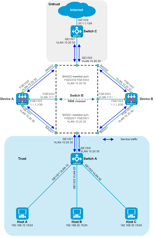
|
Device |
Interface |
IP address |
|
Host A |
N/A |
192.168.10.15/24 |
|
Host B |
N/A |
192.168.20.15/24 |
|
Host C |
N/A |
192.168.30.15/24 |
|
Switch C |
Vlan-interface10 |
192.168.10.1/24 |
|
|
Vlan-interface20 |
192.168.20.1/24 |
|
|
Vlan-interface30 |
192.168.30.1/24 |
|
|
|
20.1.1.1/24 |
|
Device A |
|
1.1.1.1/30 |
|
Device B |
|
1.1.1.2/30 |
Procedures
Configuring Switch A
Create VLAN 10, VLAN 20, and VLAN 30. Add GigabitEthernet1/0/1, GigabitEthernet1/0/2, and GigabitEthernet1/0/3 to VLAN 10, VLAN 20, and VLAN 30 respectively.
<SwitchA> system-view
[SwitchA] vlan 10
[SwitchA-vlan10] port gigabitethernet 1/0/1
[SwitchA-vlan10] quit
[SwitchA] vlan 20
[SwitchA-vlan20] port gigabitethernet 1/0/2
[SwitchA-vlan20] quit
[SwitchA] vlan 30
[SwitchA-vlan30] port gigabitethernet 1/0/3
[SwitchA-vlan30] quit
Configure the link type of GigabitEthernet1/0/4 to Trunk, and allow messages from VLAN 10, VLAN 20, and VLAN 30 to pass.
[SwitchA] interface gigabitethernet 1/0/4
[SwitchA-GigabitEthernet1/0/4] port link-type trunk
[SwitchA-GigabitEthernet1/0/4] port trunk permit vlan 10 20 30
[SwitchA-GigabitEthernet1/0/4] quit
Configuring Switch B
Create VLAN 10, VLAN 20, VLAN 30, and VLAN 1111. Add FortyGigE2/0/3 and FortyGigE3/0/3 to VLAN 1111.
<SwitchB> system-view
[SwitchB] vlan 10
[SwitchB-vlan10] quit
[SwitchB] vlan 20
[SwitchB-vlan20] quit
[SwitchB] vlan 30
[SwitchB-vlan30] quit
[SwitchB] vlan 1111
[SwitchB-vlan1111] port fortygige 2/0/3 fortygige3/0/3
[SwitchB-vlan1111] quit
Create Layer 2 aggregation interfaces 1 and 2. Configure the aggregation group corresponding to Layer 2 aggregation interface 1 to perform load sharing based on the source IP address of the packets. Configure the aggregation group corresponding to Layer 2 aggregation interface 2 to perform load sharing based on the destination IP address of the packets (ensure the consistency of the incoming and outgoing paths for the same data flow). Add ports FortyGigE2/0/1 and FortyGigE3/0/1 to aggregation group 1.
[SwitchB] interface bridge-aggregation 1
[SwitchB-Bridge-Aggregation1] link-aggregation load-sharing mode source-ip
[SwitchB-Bridge-Aggregation1] quit
[SwitchB] interface bridge-aggregation 2
[SwitchB-Bridge-Aggregation2] link-aggregation load-sharing mode destination-ip
[SwitchB-Bridge-Aggregation2] quit
[SwitchB] interface range fortygige 2/0/1 fortygige 3/0/1
[SwitchB-if-range] port link-aggregation group 1
[SwitchB-if-range] quit
[SwitchB] interface range fortygige 2/0/2 fortygige 3/0/2
[SwitchB-if-range] port link-aggregation group 2
[SwitchB-if-range] quit
Disable the MAC address learning function on Layer 2 aggregation interfaces 1 and 2 (to prevent MAC wander) and turn off the Spanning Tree Protocol (STP) (to prevent the ability of STP to shut down port forwarding and receiving messages).
[SwitchB] interface range bridge-aggregation 1 bridge-aggregation 2
[SwitchB-if-range] undo mac-address mac-learning enable
[SwitchB-if-range] undo stp enable
[SwitchB-if-range] quit
Configure the link types of GigabitEthernet1/0/1, GigabitEthernet1/0/2, and Layer 2 aggregation interfaces 1 and 2 as Trunk, and allow messages from VLAN 10, VLAN 20, and VLAN 30 to pass.
[SwitchB] interface range gigabitethernet 1/0/1 gigabitethernet 1/0/2 bridge-aggregation 1 bridge-aggregation 2
[SwitchB-if-range] port link-type trunk
[SwitchB-if-range] port trunk permit vlan 10 20 30
[SwitchB-if-range] quit
Define a class to match VLAN 10, VLAN 20, and VLAN 30.
[SwitchB] traffic classifier servicevlan
[SwitchB-classifier-host-out] if-match service-vlan-id 10 20 30
[SwitchB-classifier-host-out] quit
Define traffic behavior, with the action being to redirect to the corresponding interface.
[SwitchB] traffic behavior gigabitethernet1/0/1
[SwitchB-behavior-gigabitethernet1/0/1] redirect interface gigabitethernet 1/0/1
[SwitchB-behavior-gigabitethernet1/0/1] quit
[SwitchB] traffic behavior gigabitethernet1/0/2
[SwitchB-behavior-gigabitethernet1/0/2] redirect interface gigabitethernet 1/0/2
[SwitchB-behavior-gigabitethernet1/0/2] quit
[SwitchB] traffic behavior bagg1
[SwitchB-behavior-bagg1] redirect interface bridge-aggregation 1
[SwitchB-behavior-bagg1] quit
[SwitchB] traffic behavior bagg2
[SwitchB-behavior-bagg2] redirect interface bridge-aggregation 2
[SwitchB-behavior-bagg2] quit
Define a policy, assign traffic behavior to a class.
[SwitchB] qos policy gigabitethernet1/0/1
[SwitchB-qospolicy-gigabitethernet1/0/1] classifier servicevlan behavior gigabitethernet1/0/1
[SwitchB-qospolicy-gigabitethernet1/0/1] quit
[SwitchB] qos policy gigabitethernet1/0/2
[SwitchB-qospolicy-gigabitethernet1/0/2] classifier servicevlan behavior gigabitethernet1/0/2
[SwitchB-qospolicy-gigabitethernet1/0/2] quit
[SwitchB] qos policy bagg1
[SwitchB-qospolicy-bagg1] classifier servicevlan behavior bagg1
[SwitchB-qospolicy-bagg1] quit
[SwitchB] qos policy bagg2
[SwitchB-qospolicy-bagg2] classifier servicevlan behavior bagg2
[SwitchB-qospolicy-bagg2] quit
Apply the policy to the port's input orientation.
[SwitchB] interface gigabitethernet 1/0/1
[SwitchB-GigabitEthernet1/0/1] qos apply policy bagg1 inbound
[SwitchB-GigabitEthernet1/0/1] quit
[SwitchB] interface gigabitethernet 1/0/2
[SwitchB-GigabitEthernet1/0/2] qos apply policy bagg2 inbound
[SwitchB-GigabitEthernet1/0/2] quit
[SwitchB] interface fortygige 2/0/1
[SwitchB-FortyGigE2/0/1] qos apply policy gigabitethernet1/0/1 inbound
[SwitchB-FortyGigE2/0/1] quit
[SwitchB] interface fortygige 2/0/2
[SwitchB-FortyGigE2/0/2] qos apply policy gigabitethernet1/0/2 inbound
[SwitchB-FortyGigE2/0/2] quit
[SwitchB] interface fortygige 3/0/1
[SwitchB-FortyGigE3/0/1] qos apply policy gigabitethernet1/0/1 inbound
[SwitchB-FortyGigE3/0/1] quit
[SwitchB] interface fortygige 3/0/2
[SwitchB-FortyGigE3/0/2] qos apply policy gigabitethernet1/0/2 inbound
[SwitchB-FortyGigE3/0/2] quit
Configuring Switch C
Create VLAN 10, VLAN 20, and VLAN 20.
<SwitchC> system-view
[SwitchC] vlan 10
[SwitchC-vlan40] quit
[SwitchC] vlan 20
[SwitchC-vlan50] quit
[SwitchC] vlan 30
[SwitchC-vlan60] quit
Configure the link type of GigabitEthernet1/0/1 as Trunk, and allow packets from VLAN 10, VLAN 20, and VLAN 20 to pass.
[SwitchC] interface gigabitethernet 1/0/1
[SwitchC-GigabitEthernet1/0/1] port link-type trunk
[SwitchC-GigabitEthernet1/0/1] port trunk permit vlan 10 20 30
[SwitchC-GigabitEthernet1/0/1] quit
Create interfaces for VLAN 10, VLAN 20, and VLAN 30, and configure the IP address for the VLAN interfaces.
[SwitchC] interface vlan-interface 10
[SwitchC-Vlan-interface40] ip address 192.168.10.1 24
[SwitchC-Vlan-interface40] quit
[SwitchC] interface vlan-interface 20
[SwitchC-Vlan-interface50] ip address 192.168.20.1 24
[SwitchC-Vlan-interface50] quit
[SwitchC] interface vlan-interface 30
[SwitchC-Vlan-interface60] ip address 192.168.30.1 24
[SwitchC-Vlan-interface60] quit
Switch the working mode of GigabitEthernet1/0/2 to Layer 3, and configure its IP address.
[SwitchC] interface gigabitethernet 1/0/2
[SwitchC-GigabitEthernet1/0/2] port link-mode route
The configuration of the interface will be restored to the default. Continue? [Y]:y
[SwitchC-GigabitEthernet1/0/2] ip address 20.1.1.1 24
[SwitchC-GigabitEthernet1/0/2] quit
Configure Device A
Create VLAN10, VLAN20, and VLAN30.
<DeviceA> system-view
[DeviceA] vlan 10
[DeviceA-vlan10] quit
[DeviceA] vlan 20
[DeviceA-vlan20] quit
[DeviceA] vlan 30
[DeviceA-vlan30] quit
Switch the working modes of FortyGigE1/0/1 and FortyGigE1/0/2 to layer 2 mode.
[DeviceA] interface range fortygige 1/0/1 fortygige 1/0/2
[DeviceA-if-range] port link-mode bridge
[DeviceA-if-range] quit
Configure the link types of FortyGigE1/0/1 and FortyGigE1/0/2 as Trunk, and allow the packets from VLAN 10, VLAN 20, and VLAN 30 to pass through.
[DeviceA] interface range fortygige 1/0/1 fortygige 1/0/2
[DeviceA-if-range] port link-type trunk
[DeviceA-if-range] port trunk permit vlan 10 20 30
[DeviceA-if-range] quit
Add VLAN10, VLAN20, and VLAN30 of FortyGigE1/0/1 to the security domain Trust, and add VLAN10, VLAN20, and VLAN30 of FortyGigE1/0/2 to the security domain Untrust.
[DeviceA] security-zone name trust
[DeviceA-security-zone-Trust] import interface fortygige 1/0/1 vlan 10 20 30
[DeviceA-security-zone-Trust] quit
[DeviceA] security-zone name untrust
[DeviceA-security-zone-Untrust] import interface fortygige 1/0/2 vlan 10 20 30
[DeviceA-security-zone-Untrust] quit
Configure the security policy to allow inter-domain messages to pass.
[DeviceA] security-policy ip
[DeviceA-security-policy-ip] rule name trust-untrust
[DeviceA-security-policy-ip-0-trust-untrust] action pass
[DeviceA-security-policy-ip-0-trust-untrust] source-zone trust
[DeviceA-security-policy-ip-0-trust-untrust] destination-zone untrust
[DeviceA-security-policy-ip-0-trust-untrust] quit
[DeviceA-security-policy-ip] rule name untrust-trust
[DeviceA-security-policy-ip-1-untrust-trust] action pass
[DeviceA-security-policy-ip-1-untrust-trust] source-zone untrust
[DeviceA-security-policy-ip-1-untrust-trust] destination-zone trust
[DeviceA-security-policy-ip-1-untrust-trust] quit
[DeviceA-security-policy-ip] quit
Configure the IP address for the FortyGigE1/0/3 interface.
[DeviceA] interface fortygige 1/0/3
[DeviceA-FortyGigE1/0/3] ip address 1.1.1.1 30
[DeviceA-FortyGigE1/0/3] quit
Configure high availability (HA) RBM, monitor the state of FortyGigE1/0/1 and FortyGigE1/0/2 interfaces.
[DeviceA] remote-backup group
[DeviceA-remote-backup-group] remote-ip 1.1.1.2
[DeviceA-remote-backup-group] local-ip 1.1.1.1
[DeviceA-remote-backup-group] data-channel interface fortygige 1/0/3
[DeviceA-remote-backup-group] device-role primary
RBM_P[DeviceA-remote-backup-group] backup-mode dual-active
RBM_P[DeviceA-remote-backup-group] track interface fortygige 1/0/1
RBM_P[DeviceA-remote-backup-group] track interface fortygige 1/0/2
RBM_P[DeviceA-remote-backup-group] delay-time 1
RBM_P[DeviceA-remote-backup-group] quit
Configure Device B
Create VLAN10, VLAN20, and VLAN30.
<DeviceB> system-view
[DeviceB] vlan 10
[DeviceB-vlan10] quit
[DeviceB] vlan 20
[DeviceB-vlan20] quit
[DeviceB] vlan 30
[DeviceB-vlan30] quit
Switch the working mode of FortyGigE1/0/1 and FortyGigE1/0/2 to the Layer 2 mode.
[DeviceB] interface range fortygige 1/0/1 fortygige 1/0/2
[DeviceB-if-range] port link-mode bridge
[DeviceB-if-range] quit
Configure the link types of FortyGigE1/0/1 and FortyGigE1/0/2 as Trunk, and allow the packets of VLAN 10, VLAN 20, and VLAN 30 to pass.
[DeviceB] interface range fortygige 1/0/1 fortygige 1/0/2
[DeviceB-if-range] port link-type trunk
[DeviceB-if-range] port trunk permit vlan 10 20 30
[DeviceB-if-range] quit
Add VLAN10, VLAN20, and VLAN30 of FortyGigE1/0/1 to the security domain Trust, and add VLAN10, VLAN20, and VLAN30 of FortyGigE1/0/2 to the security domain Untrust.
[DeviceB] security-zone name trust
[DeviceB-security-zone-Trust] import interface fortygige 1/0/1 vlan 10 20 30
[DeviceB-security-zone-Trust] quit
[DeviceB] security-zone name untrust
[DeviceB-security-zone-Untrust] import interface fortygige 1/0/2 vlan 10 20 30
[DeviceB-security-zone-Untrust] quit
Configure the security policy to allow inter-domain messages to pass.
[DeviceB] security-policy ip
[DeviceB-security-policy-ip] rule name trust-untrust
[DeviceB-security-policy-ip-0-trust-untrust] action pass
[DeviceB-security-policy-ip-0-trust-untrust] source-zone trust
[DeviceB-security-policy-ip-0-trust-untrust] destination-zone untrust
[DeviceB-security-policy-ip-0-trust-untrust] quit
[DeviceB-security-policy-ip] rule name untrust-trust
[DeviceB-security-policy-ip-1-untrust-trust] action pass
[DeviceB-security-policy-ip-1-untrust-trust] source-zone untrust
[DeviceB-security-policy-ip-1-untrust-trust] destination-zone trust
[DeviceB-security-policy-ip-1-untrust-trust] quit
[DeviceB-security-policy-ip] quit
Configure the IP address of the FortyGigE1/0/3 interface.
[DeviceB] interface fortygige 1/0/3
[DeviceB-FortyGigE1/0/3] ip address 1.1.1.2 30
[DeviceB-FortyGigE1/0/3] quit
Configure high availability (HA) RBM, monitor the state of FortyGigE1/0/1 and FortyGigE1/0/2 interfaces.
[DeviceB] remote-backup group
[DeviceB-remote-backup-group] remote-ip 1.1.1.1
[DeviceB-remote-backup-group] local-ip 1.1.1.2
[DeviceB-remote-backup-group] data-channel interface fortygige 1/0/3
[DeviceB-remote-backup-group] device-role secondary
RBM_S[DeviceB-remote-backup-group] backup-mode dual-active
RBM_S[DeviceB-remote-backup-group] track interface fortygige 1/0/1
RBM_S[DeviceB-remote-backup-group] track interface fortygige 1/0/2
RBM_S[DeviceB-remote-backup-group] delay-time 1
RBM_S[DeviceB-remote-backup-group] quit
Verifying the configuration
Executing the following display command on Device A allows you to check if the HA configuration is effective, and whether the HA channel is established.
RBM_P[DeviceA] display remote-backup-group status
Remote backup group information:
Backup mode: Dual-active
Device management role: Primary
Device running status: Active
Data channel interface: FortyGigE1/0/3
Local IP: 1.1.1.1
Remote IP: 1.1.1.2 Destination port: 60064
Control channel status: Connected
Keepalive interval: 1s
Keepalive count: 10
Configuration consistency check interval: 12 hour
Configuration consistency check result: Not Performed
Configuration backup status: Auto sync enabled
Session backup status: Hot backup enabled
Delay-time: 1 min
Uptime since last switchover: 0 days, 3 hours, 11 minutes
Switchover records:
Time Status change Cause
2021-06-22 13:33:33 Initial to Active Interface status changed
You can check whether the HA configuration has taken effect and whether the HA channel has been established on Device B by executing the following display command.
RBM_S[DeviceB] display remote-backup-group status
Remote backup group information:
Backup mode: Dual-active
Device management role: Secondary
Device running status: Active
Data channel interface: FortyGigE1/0/3
Local IP: 1.1.1.2
Remote IP: 1.1.1.1 Destination port: 60064
Control channel status: Connected
Keepalive interval: 1s
Keepalive count: 10
Configuration consistency check interval: 12 hour
Configuration consistency check result: Not Performed
Configuration backup status: Auto sync enabled
Session backup status: Hot backup enabled
Delay-time: 1 min
Uptime since last switchover: 0 days, 3 hours, 12 minutes
Switchover records:
Time Status change Cause
2022-06-22 13:34:34 Initial to Active Interface status changed
On Host A, the internet connectivity was tested using a ping test. It was successful in reaching the internet address 20.1.1.1.
C:\>ping 20.1.1.1
Pinging 20.1.1.1 with 32 bytes of data:
Reply from 20.1.1.1: bytes=32 time=3ms TTL=254
Reply from 20.1.1.1: bytes=32 time=2ms TTL=254
Reply from 20.1.1.1: bytes=32 time=1ms TTL=254
Reply from 20.1.1.1: bytes=32 time=2ms TTL=254
Ping statistics for 20.1.1.1:
Packets: Sent = 4, Received = 4, Lost = 0 (0% loss),
Approximate round trip times in milli-seconds:
Minimum = 1ms, Maximum = 3ms, Average = 2ms
On Host B, perform a ping test to check the connectivity to the Internet. It can successfully ping the Internet address 20.1.1.1.
C:\>ping 20.1.1.1
Pinging 20.1.1.1 with 32 bytes of data:
Reply from 20.1.1.1: bytes=32 time=3ms TTL=254
Reply from 20.1.1.1: bytes=32 time=2ms TTL=254
Reply from 20.1.1.1: bytes=32 time=1ms TTL=254
Reply from 20.1.1.1: bytes=32 time=2ms TTL=254
Ping statistics for 20.1.1.1:
Packets: Sent = 4, Received = 4, Lost = 0 (0% loss),
Approximate round trip times in milli-seconds:
Minimum = 1ms, Maximum = 3ms, Average = 2ms
Host C is testing the connectivity to the Internet by pinging. It can
successfully ping the Internet address 20.1.1.1.
C:\>ping 20.1.1.1
Pinging 20.1.1.1 with 32 bytes of data:
Reply from 20.1.1.1: bytes=32 time=3ms TTL=254
Reply from 20.1.1.1: bytes=32 time=2ms TTL=254
Reply from 20.1.1.1: bytes=32 time=1ms TTL=254
Reply from 20.1.1.1: bytes=32 time=2ms TTL=254
Ping statistics for 20.1.1.1:
Packets: Sent = 4, Received = 4, Lost = 0 (0% loss),
Approximate round trip times in milli-seconds:
Minimum = 1ms, Maximum = 3ms, Average = 2ms
Check the session table on the Device, there exists a session table between Host and 20.1.1.1.
RBM_P[DeviceA] display session table ipv4
Slot 1:
Initiator:
Source IP/port: 192.168.10.15/12005
Destination IP/port: 20.1.1.1/2048
DS-Lite tunnel peer: -
VPN instance/VLAN ID/Inline ID: -/10/-
Protocol: ICMP(1)
Inbound interface: FortyGigE1/0/1
Source security zone: Trust
Initiator:
Source IP/port: 192.168.20.15/12005
Destination IP/port: 20.1.1.1/2048
DS-Lite tunnel peer: -
VPN instance/VLAN ID/Inline ID: -/20/-
Protocol: ICMP(1)
Inbound interface: FortyGigE1/0/1
Source security zone: Trust
Initiator:
Source IP/port: 192.168.30.15/12005
Destination IP/port: 20.1.1.1/2048
DS-Lite tunnel peer: -
VPN instance/VLAN ID/Inline ID: -/30/-
Protocol: ICMP(1)
Inbound interface: FortyGigE1/0/1
Source security zone: Trust
Configuration file
Switch A
#
vlan 10
#
vlan 20
#
vlan 30
#
interface GigabitEthernet1/0/1
port access vlan 10
#
interface GigabitEthernet1/0/2
port access vlan 20
#
interface GigabitEthernet1/0/3
port access vlan 30
#
interface GigabitEthernet1/0/4
port link-type trunk
port trunk permit vlan 10 20 30
#
Switch B
#
vlan 10
#
vlan 20
#
vlan 30
#
vlan 1111
#
traffic classifier servicevlan
if-match service-vlan-id 10 20 30
#
traffic behavior bagg1
redirect interface Bridge-Aggregation1
#
traffic behavior bagg2
redirect interface Bridge-Aggregation2
#
traffic behavior gigabitethernet1/0/1
redirect interface GigabitEthernet1/0/1
#
traffic behavior gigabitethernet1/0/2
redirect interface GigabitEthernet1/0/2
#
qos policy bagg1
classifier servicevlan behavior bagg1
#
qos policy bagg2
classifier servicevlan behavior bagg2
#
qos policy gigabitethernet1/0/1
classifier servicevlan behavior gigabitethernet1/0/1
#
qos policy gigabitethernet1/0/2
classifier servicevlan behavior gigabitethernet1/0/2
#
interface Bridge-Aggregation1
port link-type trunk
port trunk permit vlan 10 20 30
link-aggregation load-sharing mode source-ip
undo stp enable
undo mac-address mac-learning enable
#
interface Bridge-Aggregation2
port link-type trunk
port trunk permit vlan 10 20 30
link-aggregation load-sharing mode destination-ip
undo stp enable
undo mac-address mac-learning enable
#
interface GigabitEthernet1/0/1
port link-type trunk
port trunk permit vlan 10 20 30
qos apply policy bagg1 inbound
#
interface GigabitEthernet1/0/2
port link-type trunk
port trunk permit vlan 10 20 30
qos apply policy bagg2 inbound
#
interface FortyGigE2/0/1
port link-type trunk
port trunk permit vlan 10 20 30
qos apply policy gigabitethernet1/0/1 inbound
port link-aggregation group 1
#
interface FortyGigE2/0/2
port link-type trunk
port trunk permit vlan 10 20 30
qos apply policy gigabitethernet1/0/2 inbound
port link-aggregation group 2
#
interface FortyGigE2/0/3
port access vlan 1111
#
interface FortyGigE3/0/1
port link-type trunk
port trunk permit vlan 10 20 30
qos apply policy gigabitethernet1/0/1 inbound
port link-aggregation group 1
#
interface FortyGigE3/0/2
port link-type trunk
port trunk permit vlan 10 20 30
qos apply policy gigabitethernet1/0/2 inbound
port link-aggregation group 2
#
interface FortyGigE3/0/3
port access vlan 1111
#
Switch C
#
vlan 10
#
vlan 20
#
vlan 30
#
interface Vlan-interface10
ip address 192.168.10.1 255.255.255.0
#
interface Vlan-interface20
ip address 192.168.20.1 255.255.255.0
#
interface Vlan-interface30
ip address 192.168.30.1 255.255.255.0
#
interface GigabitEthernet1/0/2
port link-mode route
ip address 20.1.1.1 255.255.255.0
#
interface GigabitEthernet1/0/1
port link-type trunk
port trunk permit vlan 40 50 60
#
Device A
#
vlan 10
#
vlan 20
#
vlan 30
#
interface FortyGigE1/0/3
ip address 1.1.1.1 255.255.255.252
#
interface FortyGigE1/0/1
port link-mode bridge
port link-type trunk
port trunk permit vlan 10 20 30
#
interface FortyGigE1/0/2
port link-mode bridge
port link-type trunk
port trunk permit vlan 10 20 30
#
security-zone name Trust
import interface FortyGigE1/0/1 vlan 10 20 30
#
security-zone name Untrust
import interface FortyGigE1/0/2 vlan 10 20 30
#
security-policy ip
rule 0 name trust-untrust
action pass
source-zone trust
destination-zone untrust
rule 1 name untrust-trust
action pass
source-zone untrust
destination-zone trust
#
remote-backup group
backup-mode dual-active
data-channel interface FortyGigE1/0/3
delay-time 1
track interface FortyGigE1/0/1
track interface FortyGigE1/0/2
local-ip 1.1.1.1
remote-ip 1.1.1.2
device-role primary
#
Device B
#
vlan 10
#
vlan 20
#
vlan 30
#
interface FortyGigE1/0/3
ip address 1.1.1.2 255.255.255.252
#
interface FortyGigE1/0/1
port link-mode bridge
port link-type trunk
port trunk permit vlan 10 20 30
#
interface FortyGigE1/0/2
port link-mode bridge
port link-type trunk
port trunk permit vlan 10 20 30
#
security-zone name Trust
import interface FortyGigE1/0/1 vlan 10 20 30
#
security-zone name Untrust
import interface FortyGigE1/0/2 vlan 10 20 30
#
security-policy ip
rule 0 name trust-untrust
action pass
source-zone trust
destination-zone untrust
rule 1 name untrust-trust
action pass
source-zone untrust
destination-zone trust
#
remote-backup group
backup-mode dual-active
data-channel interface FortyGigE1/0/3
delay-time 1
track interface FortyGigE1/0/1
track interface FortyGigE1/0/2
local-ip 1.1.1.2
remote-ip 1.1.1.1
device-role secondary
#
Dual primary deployment of transparent direct path SecBlade module
Network configuration requirements
Host A, Host B, and Host C communicate with the Internet through access switch Switch A, aggregation switch Switch B, and core switch Switch C. For security reasons, two SecBlade modules, Device A and Device B, need to be deployed on the aggregation switch Switch B for security protection. The application requirements are as follows:
· Switch A assigns Host A, Host B, and Host C to VLAN 10, VLAN 20, and VLAN 30, respectively. It also transparently passes traffic between the Hosts and the Internet.
· Switch B assigns downstream service ports to VLAN 10, VLAN 20, and VLAN 30, and upstream service ports to VLAN 40, VLAN 50, and VLAN 60. The interconnection ports for upstream traffic to Device are in VLAN 10, VLAN 20, and VLAN 30, while the interconnection ports for downstream traffic from Device are in VLAN 40, VLAN 50, and VLAN 60. Upstream and downstream traffic between the Host and the Internet is transparently transmitted to the Device.
· The device's downstream services are divided into VLAN 10, VLAN 20, and VLAN 30, while upstream services are divided into VLAN 40, VLAN 50, and VLAN 60. The device forwards traffic between Host and Internet across VLANs, with Device A and Device B functioning as dual primary backups.
· Switch C serves as the gateway for Host A, Host B and Host C, forwarding the traffic between the hosts and the Internet according to the routing table.
Figure 45 The network diagram shows the deployment of two main SecBlade modules in a transparent direct path.

Figure 46 Transparent Straight-Path Dual-Master Deployment Network Diagram of Logic Group SecBlade modules.

|
Device |
Interface |
IP address |
|
Host A |
N/A |
192.168.10.15/24 |
|
Host B |
N/A |
192.168.20.15/24 |
|
Host C |
N/A |
192.168.30.15/24 |
|
Switch C |
Vlan-interface40 |
192.168.10.1/24 |
|
|
Vlan-interface50 |
192.168.20.1/24 |
|
|
Vlan-interface60 |
192.168.30.1/24 |
|
|
GE1/0/2. |
20.1.1.1/24 |
|
Device A |
Port FGE1/0/3 |
1.1.1.1/30 |
|
Device B |
FGE1/0/3 |
1.1.1.2/30 |
Procedures
Configuring Switch A
Create VLAN 10, VLAN 20, and VLAN 30. Add GigabitEthernet1/0/1, GigabitEthernet1/0/2, and GigabitEthernet1/0/3 to VLAN 10, VLAN 20, and VLAN 30, respectively.
<SwitchA> system-view
[SwitchA] vlan 10
[SwitchA-vlan10] port gigabitethernet 1/0/1
[SwitchA-vlan10] quit
[SwitchA] vlan 20
[SwitchA-vlan20] port gigabitethernet 1/0/2
[SwitchA-vlan20] quit
[SwitchA] vlan 30
[SwitchA-vlan30] port gigabitethernet 1/0/3
[SwitchA-vlan30] quit
Configure the link type of GigabitEthernet1/0/4 as Trunk, and allow the messages of VLAN 10, VLAN 20, and VLAN 30 to pass.
[SwitchA] interface gigabitethernet 1/0/4
[SwitchA-GigabitEthernet1/0/4] port link-type trunk
[SwitchA-GigabitEthernet1/0/4] port trunk permit vlan 10 20 30
[SwitchA-GigabitEthernet1/0/4] quit
Configuring Switch B
Create VLAN 10, VLAN 20, VLAN 30, VLAN 40, VLAN 50, VLAN 60, and VLAN 1111, and add FortyGigE2/0/3 and FortyGigE3/0/3 to VLAN 1111.
<SwitchB> system-view
[SwitchB] vlan 10
[SwitchB-vlan10] quit
[SwitchB] vlan 20
[SwitchB-vlan20] quit
[SwitchB] vlan 30
[SwitchB-vlan30] quit
[SwitchB] vlan 40
[SwitchB-vlan40] quit
[SwitchB] vlan 50
[SwitchB-vlan50] quit
[SwitchB] vlan 60
[SwitchB-vlan60] quit
[SwitchB] vlan 1111
[SwitchA-vlan1111] port fortygige 2/0/3 fortygige 3/0/3
[SwitchB-vlan1111] quit
Configure the link type of GigabitEthernet1/0/1 as Trunk, and allow messages from VLAN 10, VLAN 20 and VLAN 30 to pass.
[SwitchB] interface gigabitethernet 1/0/1
[SwitchB-GigabitEthernet1/0/1] port link-type trunk
[SwitchB-GigabitEthernet1/0/1] port trunk permit vlan 10 20 30
[SwitchB-GigabitEthernet1/0/1] quit
Configure the link type of GigabitEthernet1/0/2 as Trunk and allow packets from VLAN 40, VLAN 50, and VLAN 60 to pass through.
[SwitchB] interface gigabitethernet 1/0/2
[SwitchB-GigabitEthernet1/0/2] port link-type trunk
[SwitchB-GigabitEthernet1/0/2] port trunk permit vlan 40 50 60
[SwitchB-GigabitEthernet1/0/2] quit
Create Layer 2 aggregation interface 1 as a Trunk port, allowing messages from VLAN 10, VLAN 20, and VLAN 30 to pass through. Create Layer 2 aggregation interface 2 as a Trunk port, permitting messages from VLAN 40, VLAN 50, and VLAN 60. Configure the aggregation group corresponding to Layer 2 aggregation interface 1 to perform load sharing based on the source IP address of the message. Similarly, configure the aggregation group corresponding to Layer 2 aggregation interface 2 to do load sharing based on the destination IP address of the message (ensuring that the to-and-fro path of the same data flow remains consistent).
[SwitchB] interface bridge-aggregation 1
[SwitchB-Bridge-Aggregation1] port link-type trunk
[SwitchB-Bridge-Aggregation1] port trunk permit vlan 10 20 30
[SwitchB-Bridge-Aggregation1] link-aggregation load-sharing mode source-ip
[SwitchB-Bridge-Aggregation1] quit
[SwitchB] interface bridge-aggregation 2
[SwitchB-Bridge-Aggregation2] port link-type trunk
[SwitchB-Bridge-Aggregation2] port trunk permit vlan 40 50 60
[SwitchB-Bridge-Aggregation2] link-aggregation load-sharing mode destination-ip
[SwitchB-Bridge-Aggregation2] quit
Add the ports FortyGigE2/0/1 and FortyGigE3/0/1 to aggregation group 1, and the ports FortyGigE2/0/2 and FortyGigE3/0/2 to aggregation group 2.
[SwitchB] interface range fortygige 2/0/1 fortygige 3/0/1
[SwitchB-if-range] port link-aggregation group 1
[SwitchB-if-range] quit
[SwitchB] interface range fortygige 2/0/2 fortygige 3/0/2
[SwitchB-if-range] port link-aggregation group 2
[SwitchB-if-range] quit
Configuring Switch C
Create VLAN 40, VLAN 50, and VLAN 60.
<SwitchC> system-view
[SwitchC] vlan 40
[SwitchC-vlan40] quit
[SwitchC] vlan 50
[SwitchC-vlan50] quit
[SwitchC] vlan 60
[SwitchC-vlan60] quit
Configure the link type of GigabitEthernet1/0/1 as Trunk and allow packets from VLAN 40, VLAN 50, and VLAN 60 to pass.
[SwitchC] interface gigabitethernet 1/0/1
[SwitchC-GigabitEthernet1/0/1] port link-type trunk
[SwitchC-GigabitEthernet1/0/1] port trunk permit vlan 40 50 60
[SwitchC-GigabitEthernet1/0/1] quit
Create interfaces for VLAN 40, VLAN 50, and VLAN 60, and configure the IP address for the VLAN interface.
[SwitchC] interface vlan-interface 40
[SwitchC-Vlan-interface40] ip address 192.168.10.1 24
[SwitchC-Vlan-interface40] quit
[SwitchC] interface vlan-interface 50
[SwitchC-Vlan-interface50] ip address 192.168.20.1 24
[SwitchC-Vlan-interface50] quit
[SwitchC] interface vlan-interface 60
[SwitchC-Vlan-interface60] ip address 192.168.30.1 24
[SwitchC-Vlan-interface60] quit
Switch the working mode of GigabitEthernet1/0/2 to Layer 3, and configure the IP address.
[SwitchC] interface gigabitethernet 1/0/2
[SwitchC-GigabitEthernet1/0/2] port link-mode route
The configuration of the interface will be restored to the default. Continue? [Y]:y
[SwitchC-GigabitEthernet1/0/2] ip address 20.1.1.1 24
[SwitchC-GigabitEthernet1/0/2] quit
Configure Device A
Create VLAN10, VLAN20, VLAN30, VLAN40, VLAN50, and VLAN60.
<DeviceA> system-view
[DeviceA] vlan 10
[DeviceA-vlan10] quit
[DeviceA] vlan 20
[DeviceA-vlan20] quit
[DeviceA] vlan 30
[DeviceA-vlan30] quit
[DeviceA] vlan 40
[DeviceA-vlan40] quit
[DeviceA] vlan 50
[DeviceA-vlan50] quit
[DeviceA] vlan 60
[DeviceA-vlan60] quit
Switch the working mode of FortyGigE1/0/1 and FortyGigE1/0/2 to Layer 2 and configure the link type as Trunk. Allow VLAN 10, VLAN 20, and VLAN 30 traffic to pass through FortyGigE1/0/1, and allow VLAN 40, VLAN 50, and VLAN 60 traffic to pass through FortyGigE1/0/2.
[DeviceA] interface fortygige 1/0/1
[DeviceA-FortyGigE1/0/1] port link-mode bridge
[DeviceA-FortyGigE1/0/1] port link-type trunk
[DeviceA-FortyGigE1/0/1] port trunk permit vlan 10 20 30
[DeviceA-FortyGigE1/0/1] quit
[DeviceA] interface fortygige 1/0/2
[DeviceA-FortyGigE1/0/2] port link-mode bridge
[DeviceA-FortyGigE1/0/2] port link-type trunk
[DeviceA-FortyGigE1/0/2] port trunk permit vlan 40 50 60
[DeviceA-FortyGigE1/0/2] quit
Configure the IP for the FortyGigE1/0/3 interface.
[DeviceA] interface fortygige 1/0/3
[DeviceA-FortyGigE1/0/3] ip address 1.1.1.1 30
[DeviceA-FortyGigE1/0/3] quit
Add VLAN10, VLAN20, and VLAN30 to the security domain Trust, and VLAN40, VLAN50, and VLAN60 to the security domain Untrust.
[DeviceA] security-zone name trust
[DeviceA-security-zone-Trust] import vlan 10 20 30
[DeviceA-security-zone-Trust] quit
[DeviceA] security-zone name untrust
[DeviceA-security-zone-Untrust] import vlan 40 50 60
[DeviceA-security-zone-Untrust] quit
Configure the security policy to allow inter-domain messages to pass through.
[DeviceA] security-policy ip
[DeviceA-security-policy-ip] rule name trust-untrust
[DeviceA-security-policy-ip-0-trust-untrust] action pass
[DeviceA-security-policy-ip-0-trust-untrust] source-zone trust
[DeviceA-security-policy-ip-0-trust-untrust] destination-zone untrust
[DeviceA-security-policy-ip-0-trust-untrust] quit
[DeviceA-security-policy-ip] rule name untrust-trust
[DeviceA-security-policy-ip-1-untrust-trust] action pass
[DeviceA-security-policy-ip-1-untrust-trust] source-zone untrust
[DeviceA-security-policy-ip-1-untrust-trust] destination-zone trust
[DeviceA-security-policy-ip-1-untrust-trust] quit
[DeviceA-security-policy-ip] quit
Create forwarding instances for cross-VLAN forwarding modes, namely Bridge 1, Bridge 2, and Bridge 3. Then, add the VLANs that need intercommunication to these instances respectively.
[DeviceA] bridge 1 inter-vlan
[DeviceA-bridge-1-inter-vlan] add vlan 10 40
[DeviceA-bridge-1-inter-vlan] quit
[DeviceA] bridge 2 inter-vlan
[DeviceA-bridge-2-inter-vlan] add vlan 20 50
[DeviceA-bridge-2-inter-vlan] quit
[DeviceA] bridge 3 inter-vlan
[DeviceA-bridge-3-inter-vlan] add vlan 30 60
[DeviceA-bridge-3-inter-vlan] quit
Configure high availability (HA) RBM, monitoring the state of FortyGigE1/0/1 and FortyGigE1/0/2 interface.
[DeviceA] remote-backup group
[DeviceA-remote-backup-group] remote-ip 1.1.1.2
[DeviceA-remote-backup-group] local-ip 1.1.1.1
[DeviceA-remote-backup-group] data-channel interface FortyGigE 1/0/3
[DeviceA-remote-backup-group] device-role primary
RBM_P[DeviceA-remote-backup-group] backup-mode dual-active
RBM_P[DeviceA-remote-backup-group] track interface FortyGigE 1/0/1
RBM_P[DeviceA-remote-backup-group] track interface FortyGigE 1/0/2
RBM_P[DeviceA-remote-backup-group] delay-time 1
RBM_P[DeviceA-remote-backup-group] quit
Configure Device B
Create VLAN10, VLAN20, VLAN30, VLAN40, VLAN50, and VLAN60.
<DeviceB> system-view
[DeviceB] vlan 10
[DeviceB-vlan10] quit
[DeviceB] vlan 20
[DeviceB-vlan20] quit
[DeviceB] vlan 30
[DeviceB-vlan30] quit
[DeviceB] vlan 40
[DeviceB-vlan40] quit
[DeviceB] vlan 50
[DeviceB-vlan50] quit
[DeviceB] vlan 60
[DeviceB-vlan60] quit
Switch the working mode of FortyGigE1/0/1 and FortyGigE1/0/2 to layer 2 and configure the link type as Trunk. Allow VLAN 10, VLAN 20, and VLAN 30 packet to pass through FortyGigE1/0/1, and allow VLAN 40, VLAN 50, and VLAN 60 packets to pass through FortyGigE1/0/2.
[DeviceA] interface fortygige 1/0/1
[DeviceA-FortyGigE1/0/1] port link-mode bridge
[DeviceA-FortyGigE1/0/1] port link-type trunk
[DeviceA-FortyGigE1/0/1] port trunk permit vlan 10 20 30
[DeviceA-FortyGigE1/0/1] quit
[DeviceA] interface fortygige 1/0/2
[DeviceA-FortyGigE1/0/1] port link-mode bridge
[DeviceA-FortyGigE1/0/1] port link-type trunk
[DeviceA-FortyGigE1/0/1] port trunk permit vlan 40 50 60
[DeviceA-FortyGigE1/0/1] quit
Configure the IP of the FortyGigE1/0/3 interface.
[DeviceB] interface fortygige 1/0/3
[DeviceB-FortyGigE1/0/3] ip address 1.1.1.2 30
[DeviceB-FortyGigE1/0/3] quit
Add VLAN10, VLAN20, and VLAN30 to the security domain Trust, and VLAN40, VLAN50, and VLAN60 to the security domain Untrust.
[DeviceB] security-zone name trust
[DeviceB-security-zone-Trust] import vlan 10 20 30
[DeviceB-security-zone-Trust] quit
[DeviceB] security-zone name untrust
[DeviceB-security-zone-Untrust] import vlan 40 50 60
[DeviceB-security-zone-Untrust] quit
Configure the security policy to allow inter-domain messages to pass.
[DeviceB] security-policy ip
[DeviceB-security-policy-ip] rule name trust-untrust
[DeviceB-security-policy-ip-0-trust-untrust] action pass
[DeviceB-security-policy-ip-0-trust-untrust] source-zone trust
[DeviceB-security-policy-ip-0-trust-untrust] destination-zone untrust
[DeviceB-security-policy-ip-0-trust-untrust] quit
[DeviceB-security-policy-ip] rule name untrust-trust
[DeviceB-security-policy-ip-1-untrust-trust] action pass
[DeviceB-security-policy-ip-1-untrust-trust] source-zone untrust
[DeviceB-security-policy-ip-1-untrust-trust] destination-zone trust
[DeviceB-security-policy-ip-1-untrust-trust] quit
[DeviceB-security-policy-ip] quit
Create forwarding instances for cross-VLAN forwarding mode, namely Bridge 1, Bridge 2, and Bridge 3. Then add the VLANs that need intercommunication into each instance.
[DeviceB] bridge 1 inter-vlan
[DeviceB-bridge-1-inter-vlan] add vlan 10 40
[DeviceB-bridge-1-inter-vlan] quit
[DeviceB] bridge 2 inter-vlan
[DeviceB-bridge-2-inter-vlan] add vlan 20 50
[DeviceB-bridge-2-inter-vlan] quit
[DeviceB] bridge 3 inter-vlan
[DeviceB-bridge-3-inter-vlan] add vlan 30 60
[DeviceB-bridge-3-inter-vlan] quit
Configure high availability (HA) RBM, monitor the state of interface FortyGigE1/0/1 and FortyGigE1/0/2.
[DeviceB] remote-backup group
[DeviceB-remote-backup-group] remote-ip 1.1.1.1
[DeviceB-remote-backup-group] local-ip 1.1.1.2
[DeviceB-remote-backup-group] data-channel interface FortyGigE 1/0/3
[DeviceB-remote-backup-group] device-role secondary
RBM_S[DeviceB-remote-backup-group] backup-mode dual-active
RBM_S[DeviceB-remote-backup-group] track interface FortyGigE 1/0/1
RBM_S[DeviceB-remote-backup-group] track interface FortyGigE 1/0/2
RBM_S[DeviceB-remote-backup-group] delay-time 1
RBM_S[DeviceB-remote-backup-group] quit
Verifying the configuration
To check if the HA configuration has taken effect and if the HA channel has been established, execute the following display command on Device A.
RBM_P[DeviceA] display remote-backup-group status
Remote backup group information:
Backup mode: Dual-active
Device management role: Primary
Device running status: Active
Data channel interface: FortyGigE1/0/3
Local IP: 1.1.1.1
Remote IP: 1.1.1.2 Destination port: 60064
Control channel status: Connected
Keepalive interval: 1s
Keepalive count: 10
Configuration consistency check interval: 12 hour
Configuration consistency check result: Not Performed
Configuration backup status: Auto sync enabled
Session backup status: Hot backup enabled
Delay-time: 1 min
Uptime since last switchover: 0 days, 3 hours, 11 minutes
Switchover records:
Time Status change Cause
2021-06-22 13:33:33 Initial to Active Interface status changed
On Device B, execute the following display command to check whether the HA configuration takes effect and if the HA channel is established.
RBM_S[DeviceB] display remote-backup-group status
Remote backup group information:
Backup mode: Dual-active
Device management role: Secondary
Device running status: Active
Data channel interface: FortyGigE1/0/3
Local IP: 1.1.1.2
Remote IP: 1.1.1.1 Destination port: 60064
Control channel status: Connected
Keepalive interval: 1s
Keepalive count: 10
Configuration consistency check interval: 12 hour
Configuration consistency check result: Not Performed
Configuration backup status: Auto sync enabled
Session backup status: Hot backup enabled
Delay-time: 1 min
Uptime since last switchover: 0 days, 3 hours, 12 minutes
Switchover records:
Time Status change Cause
2022-06-22 13:34:34 Initial to Active Interface status changed
Host A tests connectivity to the Internet by pinging. It can successfully ping
the Internet address 20.1.1.1.
C:\>ping 20.1.1.1
Pinging 20.1.1.1 with 32 bytes of data:
Reply from 20.1.1.1: bytes=32 time=3ms TTL=254
Reply from 20.1.1.1: bytes=32 time=2ms TTL=254
Reply from 20.1.1.1: bytes=32 time=1ms TTL=254
Reply from 20.1.1.1: bytes=32 time=2ms TTL=254
Ping statistics for 20.1.1.1:
Packets: Sent = 4, Received = 4, Lost = 0 (0% loss),
Approximate round trip times in milli-seconds:
Minimum = 1ms, Maximum = 3ms, Average = 2ms
# The connectivity to the Internet can be ping tested on Host B, and the Internet address 20.1.1.1 is reachable via ping.
C:\>ping 20.1.1.1
Pinging 20.1.1.1 with 32 bytes of data:
Reply from 20.1.1.1: bytes=32 time=3ms TTL=254
Reply from 20.1.1.1: bytes=32 time=2ms TTL=254
Reply from 20.1.1.1: bytes=32 time=1ms TTL=254
Reply from 20.1.1.1: bytes=32 time=2ms TTL=254
Ping statistics for 20.1.1.1:
Packets: Sent = 4, Received = 4, Lost = 0 (0% loss),
Approximate round trip times in milli-seconds:
Minimum = 1ms, Maximum = 3ms, Average = 2ms
On Host C, a ping test for Internet connectivity is being conducted. It is possible to ping the Internet address 20.1.1.1.
C:\>ping 20.1.1.1
Pinging 20.1.1.1 with 32 bytes of data:
Reply from 20.1.1.1: bytes=32 time=3ms TTL=254
Reply from 20.1.1.1: bytes=32 time=2ms TTL=254
Reply from 20.1.1.1: bytes=32 time=1ms TTL=254
Reply from 20.1.1.1: bytes=32 time=2ms TTL=254
Ping statistics for 20.1.1.1:
Packets: Sent = 4, Received = 4, Lost = 0 (0% loss),
Approximate round trip times in milli-seconds:
Minimum = 1ms, Maximum = 3ms, Average = 2ms
Check the session table on the device, there exists a session table between the host and 20.1.1.1.
RBM_P[DeviceA] display session table ipv4
Slot 1:
Initiator:
Source IP/port: 192.168.10.15/12005
Destination IP/port: 20.1.1.1/2048
DS-Lite tunnel peer: -
VPN instance/VLAN ID/Inline ID: -/10/-
Protocol: ICMP(1)
Inbound interface: FortyGigE1/0/1
Source security zone: Trust
Initiator:
Source IP/port: 192.168.20.15/12005
Destination IP/port: 20.1.1.1/2048
DS-Lite tunnel peer: -
VPN instance/VLAN ID/Inline ID: -/20/-
Protocol: ICMP(1)
Inbound interface: FortyGigE1/0/1
Source security zone: Trust
Initiator:
Source IP/port: 192.168.30.15/12005
Destination IP/port: 20.1.1.1/2048
DS-Lite tunnel peer: -
VPN instance/VLAN ID/Inline ID: -/30/-
Protocol: ICMP(1)
Inbound interface: FortyGigE1/0/1
Source security zone: Trust
Configuration file
Switch A
#
vlan 10
#
vlan 20
#
vlan 30
#
interface GigabitEthernet1/0/1
port access vlan 10
#
interface GigabitEthernet1/0/2
port access vlan 20
#
interface GigabitEthernet1/0/3
port access vlan 30
#
interface GigabitEthernet1/0/4
port link-type trunk
port trunk permit vlan 10 20 30
#
Switch B
#
vlan 10
#
vlan 20
#
vlan 30
#
vlan 40
#
vlan 50
#
vlan 60
#
vlan 1111
#
interface Bridge-Aggregation1
port link-type trunk
port trunk permit vlan 10 20 30
link-aggregation load-sharing mode source-ip
#
interface Bridge-Aggregation2
port link-type trunk
port trunk permit vlan 40 50 60
link-aggregation load-sharing mode destination-ip
#
interface GigabitEthernet1/0/1
port link-type trunk
port trunk permit vlan 10 20 30
#
interface GigabitEthernet1/0/2
port link-type trunk
port trunk permit vlan 40 50 60
#
interface FortyGigE2/0/1
port link-aggregation group 1
#
interface FortyGigE2/0/2
port link-aggregation group 2
#
interface FortyGigE2/0/3
port access vlan 1111
#
interface FortyGigE3/0/1
port link-aggregation group 1
#
interface FortyGigE3/0/2
port link-aggregation group 2
#
interface FortyGigE3/0/3
port access vlan 1111
#
Switch C
#
vlan 40
#
vlan 50
#
vlan 60
#
interface Vlan-interface40
ip address 192.168.10.1 255.255.255.0
#
interface Vlan-interface50
ip address 192.168.20.1 255.255.255.0
#
interface Vlan-interface60
ip address 192.168.30.1 255.255.255.0
#
interface GigabitEthernet1/0/2
port link-mode route
ip address 20.1.1.1 255.255.255.0
#
interface GigabitEthernet1/0/1
port link-type trunk
port trunk permit vlan 40 50 60
#
Device A
#
vlan 10
#
vlan 20
#
vlan 30
#
vlan 40
#
vlan 50
#
vlan 60
#
bridge 1 inter-vlan
add vlan 10 40
#
bridge 2 inter-vlan
add vlan 20 50
#
bridge 3 inter-vlan
add vlan 30 60
#
interface FortyGigE1/0/3
ip address 1.1.1.1 255.255.255.252
#
interface FortyGigE1/0/1
port link-mode bridge
port link-type trunk
port trunk permit vlan 10 20 30
#
interface FortyGigE1/0/2
port link-mode bridge
port link-type trunk
port trunk permit vlan 40 50 60
#
security-zone name Trust
import vlan 10 20 30
#
security-zone name Untrust
import vlan 40 50 60
#
security-policy ip
rule 0 name trust-untrust
action pass
source-zone trust
destination-zone untrust
rule 1 name untrust-trust
action pass
source-zone untrust
destination-zone trust
#
remote-backup group
backup-mode dual-active
data-channel interface FortyGigE1/0/3
delay-time 1
track interface FortyGigE1/0/1
track interface FortyGigE1/0/2
local-ip 1.1.1.1
remote-ip 1.1.1.2
device-role primary
#
Device B
#
vlan 10
#
vlan 20
#
vlan 30
#
vlan 40
#
vlan 50
#
vlan 60
#
bridge 1 inter-vlan
add vlan 10 40
#
bridge 2 inter-vlan
add vlan 20 50
#
bridge 3 inter-vlan
add vlan 30 60
#
interface FortyGigE1/0/3
ip address 1.1.1.2 255.255.255.252
#
interface FortyGigE1/0/1
port link-mode bridge
port link-type trunk
port trunk permit vlan 10 20 30
#
interface FortyGigE1/0/2
port link-mode bridge
port link-type trunk
port trunk permit vlan 40 50 60
#
security-zone name Trust
import vlan 10 20 30
#
security-zone name Untrust
import vlan 40 50 60
#
security-policy ip
rule 0 name trust-untrust
action pass
source-zone trust
destination-zone untrust
rule 1 name untrust-trust
action pass
source-zone untrust
destination-zone trust
#
remote-backup group
backup-mode dual-active
data-channel interface FortyGigE1/0/3
delay-time 1
track interface FortyGigE1/0/1
track interface FortyGigE1/0/2
local-ip 1.1.1.2
remote-ip 1.1.1.1
device-role secondary
#
