- Released At: 12-12-2024
- Page Views:
- Downloads:
- Table of Contents
- Related Documents
-
H3C Campus Network Optical Slicing Technology White Paper
Copyright © 2024 New H3C Technologies Co., Ltd. All rights reserved.
No part of this manual may be reproduced or transmitted in any form or by any means without prior written consent of New H3C Technologies Co., Ltd.
Except for the trademarks of New H3C Technologies Co., Ltd., any trademarks that may be mentioned in this document are the property of their respective owners.
This guide describes only the most common information for lightning protection. Some information might not be applicable to your products.
Mechanism for network slicing based on packet mapping
Radio-based network slicing operating mechanism
Comparison of network slicing technologies
Overview
Technical background
Campus network slicing is an innovative technology that integrates network slicing with campus networks. The core of this technology is end-to-end slicing and scheduling of campus network resources across all scenarios. This provides customized network services for different applications. Using multiple logical network slices allows for independent traffic transmission and highly flexible configuration of network resources to address requirements of different industries and users within the campus.
Technical advantages
Campus network optical slicing offers the following advantages:
· Addressing differentiated Service Level Agreement (SLA) requirements—Services vary in their network requirements. Conventional physical networks cannot address diverse SLA requirements such as latency, bandwidth, and reliability. Network slicing solutions can provide tailored network slices on-demand, meeting their individual network performance needs. For example, teleconferencing requires strict control over latency and jitter, whereas video surveillance has high bandwidth demands but no special requirements for latency. Network slicing can deliver customized network services based on service requirements to achieve differentiated SLAs.
· Accommodating various endpoint access methods—The sliced network is agnostic to endpoint access methods. As long as the incoming traffic meets the slicing mapping rules, it can be forwarded using the resources of the sliced network.
· Simple configuration and implementation—Network slicing can be achieved simply by configuring the mapping relationship between packets and slices, as well as the bandwidth of the slicing channels.
Implementation
The primary concept behind the campus network optical slicing solution is to associate packets with a specific slice network based on characteristics such as DSCP, VLAN, and VXLAN. Packets are then forwarded through the resources of the associated slice network. Different slice networks use different queuing systems for scheduling, ensuring that packets belonging to higher-priority slice networks are given precedence in processing.
Basic concepts
Network slicing defines the following concepts:
· Network slice instance—Within a network environment deployed with network slicing, each separate virtual network is a network slice instance. Each virtual network is identified by a unique network slice instance ID.
· Network slice packet—A packet bound to a designated network slice instance ID based on characteristics such as DSCP, VLAN, and VXLAN. When forwarded, this tagged packet is transmitted within the corresponding network slice instance.
· Network slice channel—A logical channel used on a device interface to forward network slice packets. Network slice channels are also identified by the network slice instance ID and are associated with the network slice instance. Multiple network slice channels can be created on each interface, with independent scheduling queues allocated to each channel. The scheduling queues for different network slice channels do not interfere with each other.
Mechanism for network slicing based on packet mapping
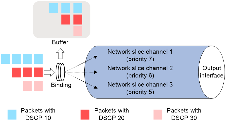
As shown in Figure 1, network optical slicing based on packet mapping operates as follows:
1. The device maps specific packets to their corresponding network slice channels on the output interface for forwarding based on the configured binding relationship between packet types and network slice instance IDs. Packet mapping is supported based on criteria such as the packet's DSCP value, VLAN value, VXLAN value, the packet's input interface, or the VSI to which the packet belongs. As shown in the figure, packets with DSCP 10 are mapped to network slice channel 2, those with DSCP 20 to network slice channel 3, and those with DSCP 30 to network slice channel 1.
2. Before being forwarded through the network slice channel at the output interface, packets first pass through the outbound buffer. If there is network congestion on the outbound path, the buffer helps prevent packet loss. For packets bound to different network slice instance IDs, you can adjust the cache level of their buffer. The higher the cache level, the more buffer space is available for the packets in that network slice channel.
3. Each network slice channel on the interface can have a specified guaranteed bandwidth. Different network slice channels are scheduled using different queues without interference from each other, ensuring the bandwidth resources for services.
4. When packets are forwarded through the network slice channel, they are scheduled based on the priority of the network slice channel, using a strict priority scheduling mechanism. If there is network congestion at the output interface, packets in higher-priority network slice channels are forwarded first. Packets from lower-priority network slice channels can be scheduled only after all packets from higher-priority channels are dequeued. For network slice channels with the same scheduling priority, a weighted round-robin method is used for scheduling.
Figure 1 Network slicing mechanism based on packet mapping
Radio-based network slicing operating mechanism
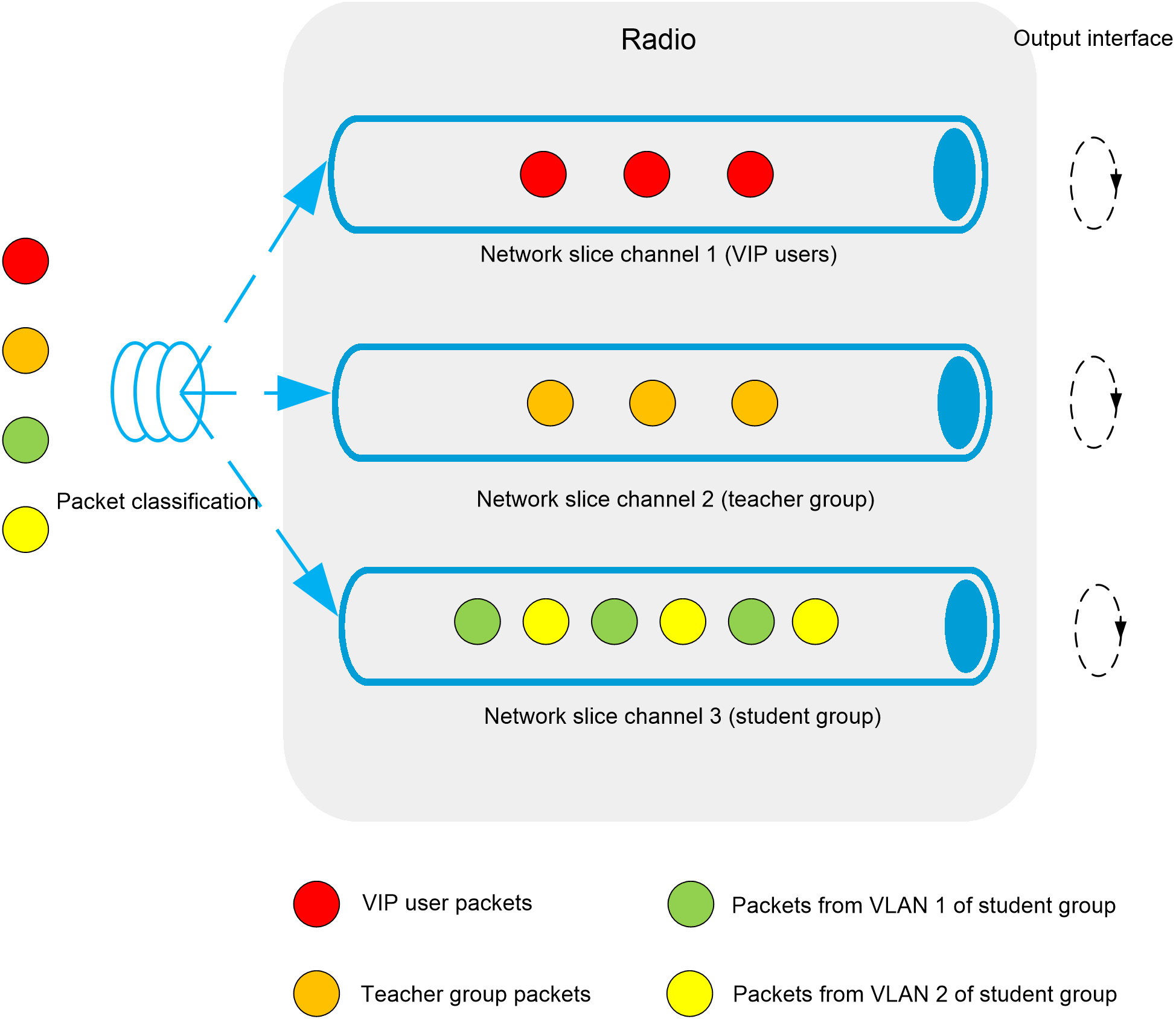
As shown in Figure 2, radio-based network slicing operates as follows:
1. The device maps specific packets to the corresponding network slice channels on the radio based on the configured binding relationship between packet types and radio slices. The establishment of binding relationships between packets and radio slices is supported based on characteristics such as VLAN values, MAC addresses, and wireless service templates. In the figure, packets are mapped to different network slice channels based on user group VLANs authorized for the packets. VIP users are mapped to slice channel 1, teacher groups to slice channel 2, and student groups with different VLANs to slice channel 3.
Binding slices based on client MAC addresses can allow a single user to exclusively use a slice, achieving guaranteed bandwidth for specific users.
2. Each radio slice channel on the radio can have a specified guaranteed bandwidth, with different clients within the radio slice channel sharing the guaranteed bandwidth of the slice equally. If no clients match the rules, the bandwidth is not reserved and is available for other clients to use. When multiple radio slices exist on a single radio, slicing rules are matched according to the priority of the radio slices. In cases where multiple slices exist and the reserve bandwidth exceeds the total bandwidth capacity, once the reserved bandwidth is fully allocated, any amount that exceeds the total capacity will not be allocated.
Figure 2 Radio-based network slicing operating mechanism
Comparison of network slicing technologies
With the large-scale commercialization of 5G networks, a variety of network slicing technologies have emerged, offering more flexible and customizable network services for different application scenarios. This section compares campus network optical slicing with several other mainstream network slicing technologies, analyzing their advantages and disadvantages in aspects such as resource allocation, quality of service guarantees, and application scenarios, helping you better understand and select an appropriate network slicing technology.
Table 1 Network slicing technology comparison
|
Technology/project |
Network optical slicing |
Slice ID based SRv6 network slicing |
Wave slicing |
PON slicing |
|
Implementation |
Data forwarding based on packet mapping. |
The link bandwidth resources are sliced based on the slice ID, and then packets carrying the slice ID are identified for forwarding across different slices on the forwarding plane. |
Different wavelengths carry different service data. |
Data forwarding based on dynamic bandwidth allocation. |
|
Supported protocol packets |
Ethernet protocol packets. |
IPv6 protocol packets. |
OTN packets. |
GPON protocol packets. |
|
Applicable scenarios |
Campus access networks. |
Transport networks and backbone networks. |
OTN networks. |
Broadband access networks. |
Typical applications
Campus network with packet mapping-based slicing
In a campus network, there are various types of business traffic, such as educational network device and video surveillance traffic. To achieve refined management of service traffic and ensure that the educational network has independent and highly reliable network resources and video surveillance is allocated network resources with higher bandwidth, different types of service traffic can be mapped to different network slices for transmission and forwarding.
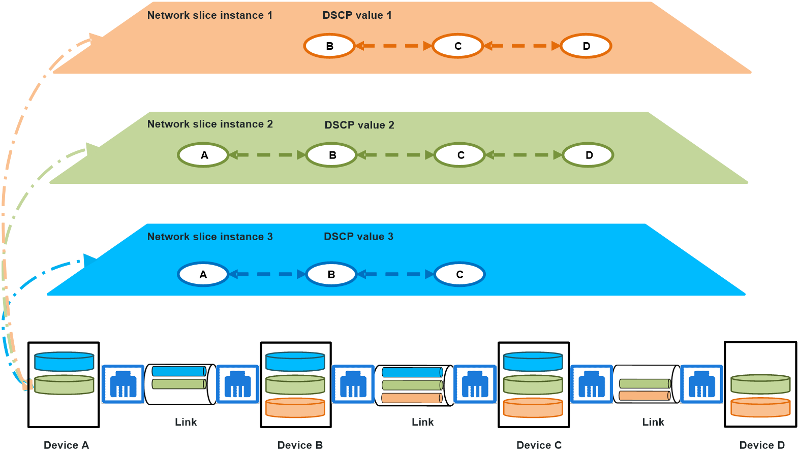
As shown in Figure 3, traffic from educational network devices, video surveillance devices, and other devices is transmitted through different access switches to upstream aggregation switch Device A, which then forwards the traffic to the carrier network or campus servers through core switch Device B. In the inbound direction of Device A, packets received from different interfaces can be bound to different network slice channels, with different DSCP values assigned for scheduling and forwarding. On Device B, traffic is mapped to the corresponding network slice channels for forwarding based on the packet's DSCP value. With this method, service traffic within the campus network can be effectively managed and optimized.
Figure 3 Campus network with packet mapping-based slicing
Radio slicing-based campus office network
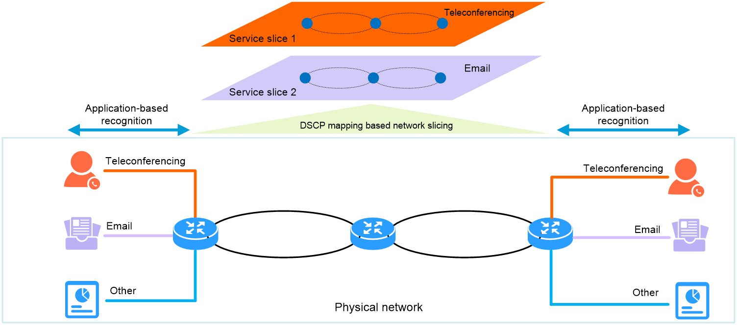
As shown in Figure 4, critical service traffic (such as teleconferencing and email) often requires dedicated protection to prevent the traffic from being affected by other traffic on the same client. You can configure application-based recognition on campus access point devices (APs) and campus egress devices (firewalls). Different application flows are bound to different slices, and each slice is configured with guaranteed bandwidth.
For intermediate optical network devices, application traffic is configured with different DSCP values on the edge devices, APs, and firewalls, and mapped to different slice channels for forwarding. In addition, guaranteed bandwidth is configured for each slice to achieve end-to-end application-based network slicing configuration across the network.
Figure 4 Radio slicing-based campus office network