- Table of Contents
- Related Documents
-
| Title | Size | Download |
|---|---|---|
| 04-Cables | 639.03 KB |
Contents
Connecting a DB9-to-RJ45 console cable
Connecting a USB-to-RJ45 console cable
Making an Ethernet twisted pair cable
QSFP+ to SFP+/QSFP28 to SFP28 copper cable
4 Cables
This chapter describes cables used for connecting network ports.
|
Cable |
Port type |
Application |
|
· RJ-45 Ethernet port at one end and DB-9 port at the other end · RJ-45 Ethernet port at one end and USB port at the other end |
Connects the console port of the device to the console terminal |
|
|
RJ-45 Ethernet ports |
Connects RJ-45 Ethernet ports to transmit data |
|
|
SFP/SFP+/SFP28/QSFP+/QSFP28 ports |
Connects the fiber ports to transmit data |
|
|
SFP+/SFP28 ports |
Connects SFP+/SFP28 ports to transmit data |
|
|
SFP+/SFP28 ports |
Connects SFP+/SFP28 ports to transmit data |
|
|
QSFP+ ports |
Connects QSFP+ ports to transmit data |
|
|
QSFP28 ports |
Connects QSFP28 ports to transmit data |
|
|
QSFP+/QSFP28 ports |
Connects QSFP+/QSFP28 ports to transmit data |
|
|
QSFP-DD ports |
Connects QSFP-DD ports to transmit data |
|
|
QSFP+ port at one end and SFP+ port at the other end |
Connects QSFP+ port at one end and SFP+ port at the other end |
|
|
QSFP28 port at one end and SFP28 port at the other end |
Connects QSFP28 port at one end and SFP28 port at the other end |
Console cable
As shown in Table 4-1, two types of serial console cables can be used for connecting the device to a configuration terminal. The device is not provided with a serial console cable.
Table 4-1 Connection methods and console cables
|
Connection method |
Console cable type |
Configuration terminal-side connector |
Device-side connector |
|
Using the serial console port for connection |
DB9-to-RJ45 console cable |
DB-9 female connector |
RJ-45 connector |
|
USB-to-RJ45 console cable |
USB connector |
RJ-45 connector |
The signal pinout for the RJ-45 connector of a serial console cable varies by vendor. To avoid abnormal configuration terminal display, use a serial console cable provided by H3C. For more information, see Table 4-2. To prepare a serial console cable yourself, make sure the signal pinout for the RJ-45 connector is the same as that shown in Table 4-3.
|
Console cable type |
Console cable view |
Product code for the recommended H3C console cable |
|
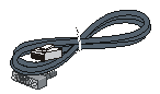
DB9-to-RJ45 console cable |
|
04042967 |
|
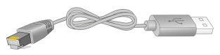
USB-to-RJ45 console cable |
|
0404A1EE |
Connecting a DB9-to-RJ45 console cable
|
|
CAUTION: Follow these guidelines when you connect a DB9-to-RJ45 console cable: · Identify the mark on the console port and make sure you are connecting to the correct port. · The serial ports on PCs do not support hot swapping. To connect a PC to an operating device, first connect the PC end. To disconnect a PC from an operating device, first disconnect the device end. |
A DB9-to-RJ45 console cable is an 8-core shielded cable, with a crimped RJ-45 connector at one end for connecting to the console port of the device, and a DB-9 female connector at the other end for connecting to the serial port on the console terminal.
Figure 4-1 Console cable
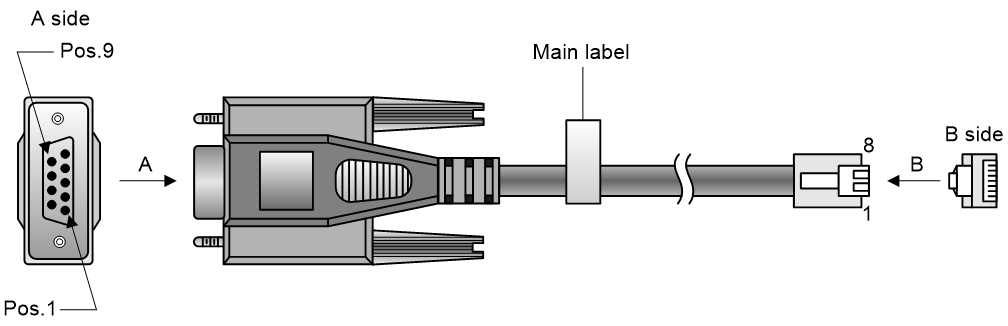
Table 4-3 DB9-to-RJ45 console cable signal pinout
|
RJ-45 |
Signal |
DB-9 |
Signal |
|
1 |
RTS |
8 |
CTS |
|
2 |
DTR |
6 |
DSR |
|
3 |
TXD |
2 |
RXD |
|
4 |
SG |
5 |
SG |
|
5 |
SG |
5 |
SG |
|
6 |
RXD |
3 |
TXD |
|
7 |
DSR |
4 |
DTR |
|
8 |
CTS |
7 |
RTS |
To connect the device to a configuration terminal (for example, a PC) by using a DB9-to-RJ45 console cable:
1. Plug the DB-9 female connector of the DB9-to-RJ45 console cable to the serial port on the PC.
2. Connect the RJ-45 connector to the console port on the device.
Connecting a USB-to-RJ45 console cable
|
|
IMPORTANT: · To use a USB-to-RJ45 console cable to connect the device to a configuration terminal, first download and install the USB-to-RJ45 console driver on the configuration terminal, and then connect the USB-to-RJ45 console cable to the configuration terminal. · If you have connected a USB-to-RJ45 console cable to the configuration terminal before by using driver, remove and reconnect the USB-to-RJ45 console cable to the configuration terminal after driver installation. |
For information about the signal pinout for the RJ-45 connector of a USB-to-RJ45 console cable, see Table 4-3.
The following installs the driver on the Windows system. To install the driver on other operating systems, see the installation guide in the driver compression package named by using the corresponding operating system.
To connect the device to a configuration terminal by using a USB-to-RJ45 console cable:
1. Click the following link, or copy it to the address bar on your browser and download the USB-to-RJ45 console driver.
http://www.h3c.com/en/home/USB_to_RJ45_Console/
2. View the TXT file Read me in the Windows folder to check whether the Windows system of the configuration terminal supports the driver.
3. If the Windows system supports the driver, install PL23XX-M_LogoDriver_Setup_v200_20190815.exe.
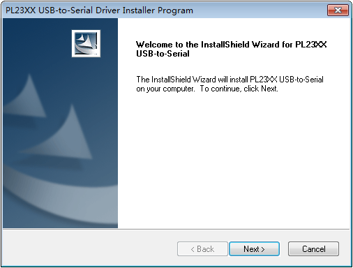
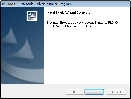
4. Click Next on the welcome page of the driver installation wizard.
Figure 4-2 Driver installation wizard
5. Click Finish after the drive installation is completed.
Figure 4-3 Finishing the driver installation
6. Connect the standard USB connector of the cable to the USB port of the configuration terminal.
7. Connect the RJ-45 connector of the cable to the console port of the device.
Ethernet twisted pair cable
An Ethernet twisted pair cable consists of four pairs of insulated wires twisted together. It mainly transmits analog signals and is advantageous in transmitting data over shorter distances. The maximum transmission distance is 100 m (328.08 ft).
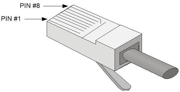
RJ-45 connector
An Ethernet twisted pair cable connects network devices through the RJ-45 connectors at the two ends. Figure 4-4 shows the pinouts of an RJ-45 connector.
Figure 4-4 RJ-45 connector pinout diagram
Cable pinouts
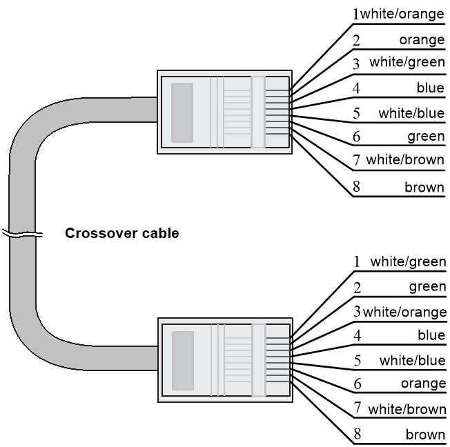
EIA/TIA cabling specifications define two standards: 568A and 568B for cable pinouts.
· Standard 568A—pin 1: white/green stripe, pin 2: green solid, pin 3: white/orange stripe, pin 4: blue solid, pin 5: white/blue stripe, pin 6: orange solid, pin 7: white/brown stripe, pin 8: brown solid.
· Standard 568B—pin 1: white/orange stripe, pin 2: orange solid, pin 3: white/green stripe, pin 4: blue solid, pin 5: white/blue stripe, pin 6: green solid, pin 7: white/brown stripe, pin 8: brown solid.
Cable type
Based on performance
Table 4-4 Ethernet cable description
|
Type |
Description |
|
Category 5 |
Transmits data at a maximum speed of 100 Mbps, with a bandwidth of 100 MHz. |
|
Category 5e |
Transmits data at a maximum speed of 1000 Mbps, with a bandwidth of 100 MHz. |
|
Category 6 |
Transmits data at a speed higher than 1 Gbps, with a bandwidth of 250 MHz. |
|
Category 6A |
Transmits data at a speed higher than 10 Gbps, with a bandwidth of 500 MHz. |
|
Category 7 |
Transmits data at a speed higher than 10 Gbps, with a bandwidth of 600 MHz. |
Based on pinouts
Ethernet twisted pair cables can be classified into straight through and crossover cables based on their pinouts.
· Straight-through—The pinouts at both ends comply with standard 568B, as shown in Figure 4-5.
· Crossover—The pinouts at one end comply with standard 568B, and those at the other end comply with standard 568A, as shown in Figure 4-6.
Figure 4-5 Straight-through cable

Pin assignments
Select an Ethernet twisted pair cable according to the RJ-45 Ethernet port type on your device. An RJ-45 Ethernet port can be MDI (on routers and PCs) or MDIX (on the device). For the pinouts of RJ-45 Ethernet ports, see Table 4-5 and Table 4-6.
Table 4-5 RJ-45 MDI interface pinouts
|
10Base-T/100Base-TX |
1000Base-T |
|||
|
Signal |
Function |
Signal |
Function |
|
|
1 |
Tx+ |
Send data |
BIDA+ |
Bi-directional data cable A+ |
|
2 |
Tx- |
Send data |
BIDA- |
Bi-directional data cable A- |
|
3 |
Rx+ |
Receive data |
BIDB+ |
Bi-directional data cable B+ |
|
4 |
Reserved |
N/A |
BIDC+ |
Bi-directional data cable C+ |
|
5 |
Reserved |
N/A |
BIDC- |
Bi-directional data cable C- |
|
6 |
Rx- |
Receive data |
BIDB- |
Bi-directional data cable B- |
|
7 |
Reserved |
N/A |
BIDD+ |
Bi-directional data cable D+ |
|
8 |
Reserved |
N/A |
BIDD- |
Bi-directional data cable D- |
Table 4-6 RJ-45 MDI-X interface pinouts
|
Pin |
10Base-T/100Base-TX |
1000Base-T |
||
|
Signal |
Function |
Signal |
Function |
|
|
1 |
Rx+ |
Receive data |
BIDB+ |
Bi-directional data cable B+ |
|
2 |
Rx- |
Receive data |
BIDB- |
Bi-directional data cable B- |
|
3 |
Tx+ |
Send data |
BIDA+ |
Bi-directional data cable A+ |
|
4 |
Reserved |
N/A |
BIDD+ |
Bi-directional data cable D+ |
|
5 |
Reserved |
N/A |
BIDD- |
Bi-directional data cable D- |
|
6 |
Tx- |
Send data |
BIDA- |
Bi-directional data cable A- |
|
7 |
Reserved |
N/A |
BIDC+ |
Bi-directional data cable C+ |
|
8 |
Reserved |
N/A |
BIDC- |
Bi-directional data cable C- |
To ensure normal communication, the pins for sending data on one port should correspond to the pins for receiving data on the peer port. When both of the ports on the two devices are MDI or MDIX, a crossover Ethernet cable is needed. A cross-over cable connects devices of the same type. When one port is MDI and the other is MDIX, a straight-through Ethernet cable is needed. A straight-through cable connects devices of different types.
An RJ-45 Ethernet port with MDI/MDIX autosensing enabled can automatically negotiate pin roles. The RJ-45 Ethernet ports on the device support auto-MDI/MDIX. By default, auto-MDI/MDIX is enabled on a port.
Making an Ethernet twisted pair cable
1. Cut the cable to length with the crimping pliers.
2. Strip off an appropriate length of the cable sheath. The length is typically that of the RJ-45 connector.
3. Untwist the pairs so that they can lie flat, and arrange the colored wires based on the wiring specifications.
4. Cut the top of the wires even with one another. Insert the wires into the RJ-45 end and make sure the wires extend to the front of the RJ-45 end and make good contact with the metal contacts in the RJ-45 end and in the correct order.
5. Crimp the RJ-45 connector with the crimping pliers until you hear a click.
6. Repeat the above steps with the other end of the cable.
7. Use a cable tester to verify the connectivity of the cable.
Optical fiber
|
|
CAUTION: Use the same types of transceiver modules, pigtail cords, patch cords, and fiber cables. If you use single-mode optical fibers, the transceiver modules, pigtail cords, patch cords, and fiber cables must be single-mode. |
Optical fiber
Optical fibers are widely used in fiber-optic communications, which are advantageous for long-distance communications.
Optical fibers can be classified into the following types:
· Single mode fiber—It has a core size of 10 µm or smaller, and has a lower modal dispersion. It carries only a single ray of light. It is mostly used for communication over longer distances.
· Multi-mode fiber—It has a core size of 50 µm or 62.5 µm or higher, and has a higher modal dispersion than single-mode optical fiber. It is mostly used for communication over shorter distances.
Table 4-7 Allowed maximum tensile force and crush load
|
Period of force |
Tensile load (N) |
Crush load (N/mm) |
|
Short period |
150 |
500 |
|
Long term |
80 |
100 |
Optical fiber cable
An optical fiber cable is a cable containing one or more optical fibers. The optical fiber elements are typically individually coated with plastic layers and contained in a protective tube. Optical fiber cables fall into single-mode and multi-mode.
Patch cord
A fiber that has connectors at both ends is called a patch cord. A patch cord connects one optical device to another for signal routing. Patch cords fall into single-mode and multi-mode patch cords.
· Single-mode patch cord—The jacket is yellow. It permits transmission over longer distances.
· Multi-mode patch cord—The jacket is orange. It permits transmission over shorter distances.
Patch cords are classified into SC, LC, FC, and so on based on interface type. The length of a patch cord can be 0.5 m (1.64 ft), 1 m (3.28 ft), 2 m (6.56 ft), 3 m (9.84 ft), 5 m (16.40 ft), 10 m (32.81 ft), and so on.
Pigtail cord
A pigtail cord is an optical fiber that has an optical connector on one end and a length of exposed fiber on the other. The end of the pigtail is fusion spliced to a fiber, connecting the fiber cable and transceiver.
Pigtail cords fall into single-mode (yellow) and multi-mode (orange), and can also be classified into SC, LC, FC, and so on based on interface type.
Fiber connector
Figure 4-7 MPO connector
Precautions
· Make sure the fiber connector and fiber type match the transceiver module type.
· The fiber ports on the device are provided with dust plugs. Insert the dust plugs into the fiber ports that you are not to use, to prevent particles from entering the ports.
· Fiber connectors must be protected under safe and reliable outer packing, and be fitted with dust caps. Fiber connectors must be installed with dust caps when they are not in use. Take care not to scratch their end face. Replace the dust cap if it is loose or polluted.
· Before connecting a fiber, use dust free paper and absolute alcohol to clean the end face of the fiber connector. You can brush the end face only in one direction. You also need to brush the end face of the fiber port.
· If the fiber has to pass through a metallic board hole, the hole must have a sleek and fully filleted surface (the filleting radius must be not less than 2 mm). When passing through a metallic board hole or bending along the acute side of mechanical parts, the fiber must wear jackets or cushions.
· Insert and remove a plug with care. Never exert a fierce force to the fiber or plug; otherwise the plug might be damaged or the fiber might be broken. Never pull, press or extrude the fiber fiercely. For the allowed maximum tensile load and crush load, see Table 4-7.
SFP+/SFP28 copper cable
You can use SFP+ copper cables to connect the SFP+ ports. The SFP+ copper cables available for the device are 10 G SFP+ Cu cables, as shown in Figure 4-9.
You can use SFP28 copper cables to connect SFP28 ports. The SFP28 copper cables are similar to SFP+ copper cables in appearance.
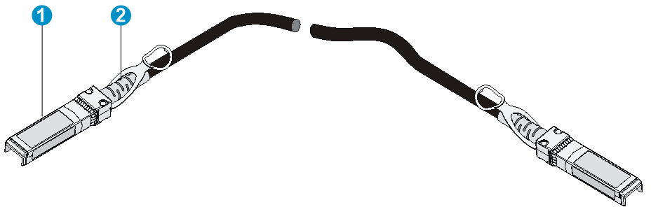
|
(1) Connector |
(2) Pull latch |
SFP+ AOC/SFP28 AOC cable
You can use SFP+ AOC cables to connect SFP+ ports.
You can use SFP28 AOC cables to connect SFP28 ports. The SFP28 AOC cables are similar to SFP+ AOC cables in appearance.
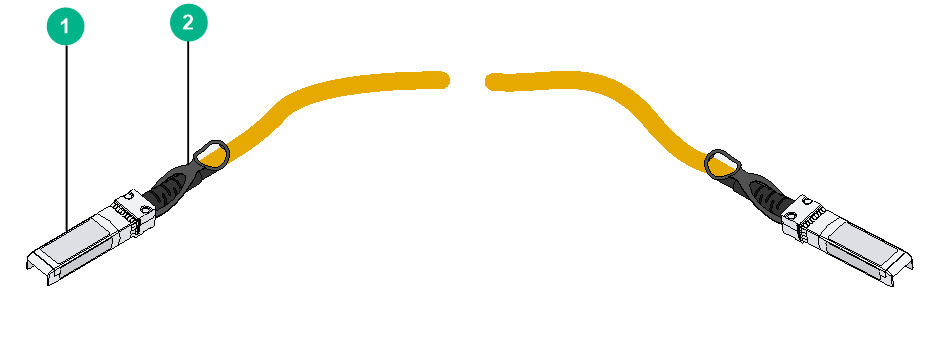
|
(1) Connector |
(2) Pull latch |
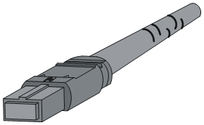
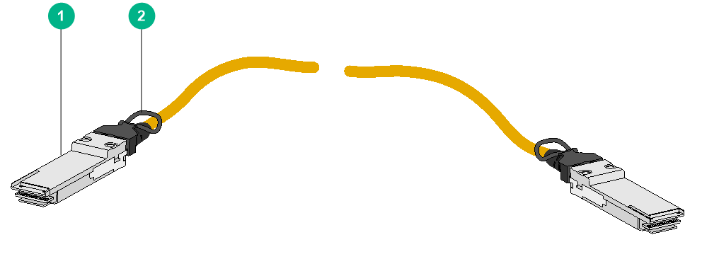
QSFP+ copper cable
You can use QSFP+ copper cables to connect the QSFP+ ports.
Figure 4-11 QSFP+ copper cable
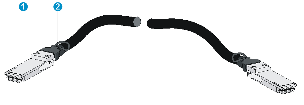
|
(1) Connector |
(2) Pull latch |
QSFP28 copper cable
You can use QSFP28 copper cables to connect the QSFP28 ports.
Figure 4-12 QSFP28 copper cable

|
(1) Connector |
(2) Pull latch |
QSFP+ AOC/QSFP28 AOC cable
You can use QSFP+ AOC cables to connect QSFP+ ports.
You can use QSFP28 AOC cables to connect QSFP28 ports. The QSFP28 AOC cables are similar to QSFP+ AOC cables in appearance.
Figure 4-13 QSFP+ AOC cable
|
(1) Connector |
(2) Pull latch |
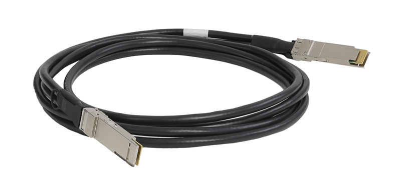
QSFP-DD copper cable
You can use QSFP-DD copper cables to connect the QSFP-DD ports.
Figure 4-14 QSFP-DD copper cable
QSFP+ to SFP+/QSFP28 to SFP28 copper cable
A QSFP+ to SFP+ copper cable is a cable with one QSFP+ module at one end and four SFP+ modules at the other end.
A QSFP28 to SFP28 copper cable is a cable with one QSFP28 module at one end and four SFP28 modules at the other end. The QSFP28 to SFP28 copper cables are similar to QSFP+ to SFP+ copper cables in appearance.
Figure 4-15 QSFP+ to SFP+ copper cable
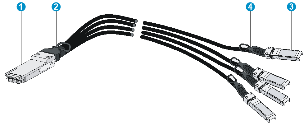
|
(1) QSFP+ connector |
(2) QSFP+ pull latch |
|
(3) SFP+ connector |
(4) SFP+ pull latch |
