- Table of Contents
- Related Documents
-
| Title | Size | Download |
|---|---|---|
| 01-Chassis Views and Technical Specifications | 20.24 MB |
Contents
1 Chassis views and technical specifications
Module power consumption and system power consumption
1 Chassis views and technical specifications
The H3C S12500R Ethernet Switch Router Series is a set of next-generation rack switch routers designed for data center core networks. It optimizes the CLOS switching fabric architecture and uses the variable cell-based traffic scheduling and control forwarding mechanism to deliver higher forwarding efficiency, more refined congestion control, and hierarchical scheduling.
Unless otherwise stated, MPUs, service modules, fabric modules, environment management modules, and power modules are collectively referred to as "modules" in this document. MPUs and SEUs, and power modules and power supplies are used interchangeably in this document, respectively.
H3C S12500R switch router series includes the S12516R, S12508R, S12504R, S12516CR, S12508CR, S12500R-2XL, and S12500R-2L models.
Chassis views
Figure 1-1 S12516R
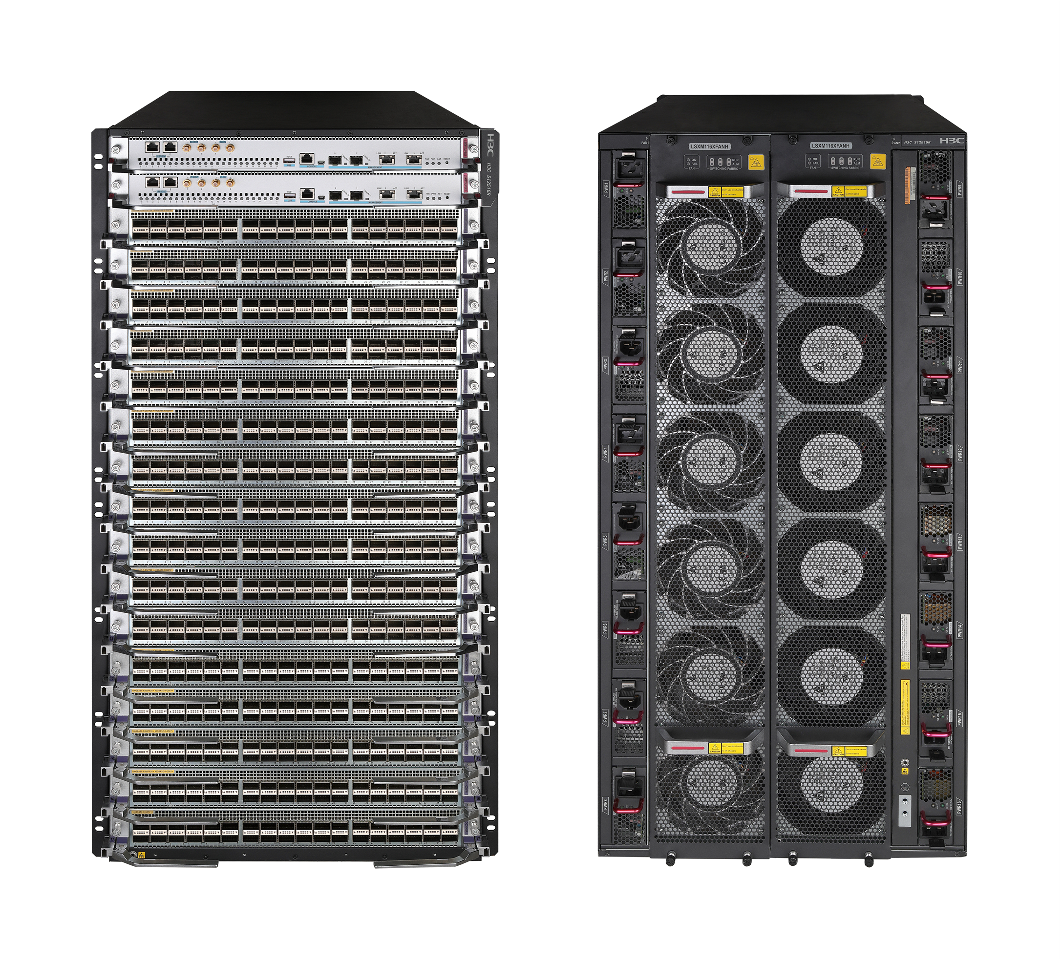
Figure 1-2 S12508R
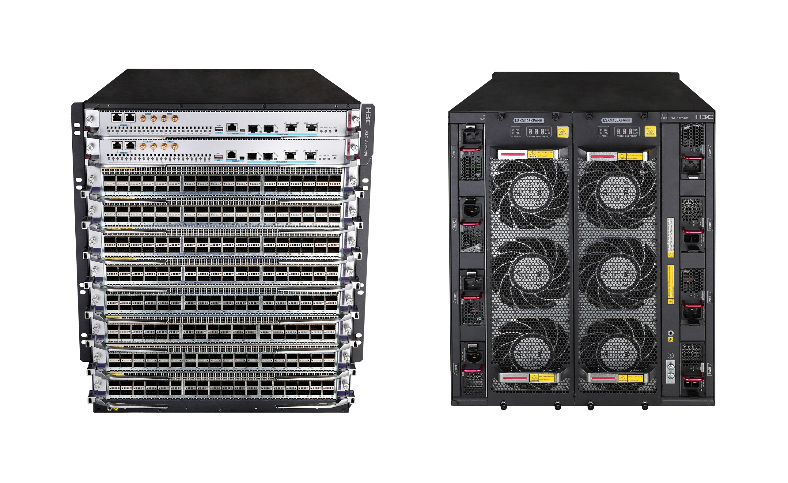
Figure 1-3 S12504R
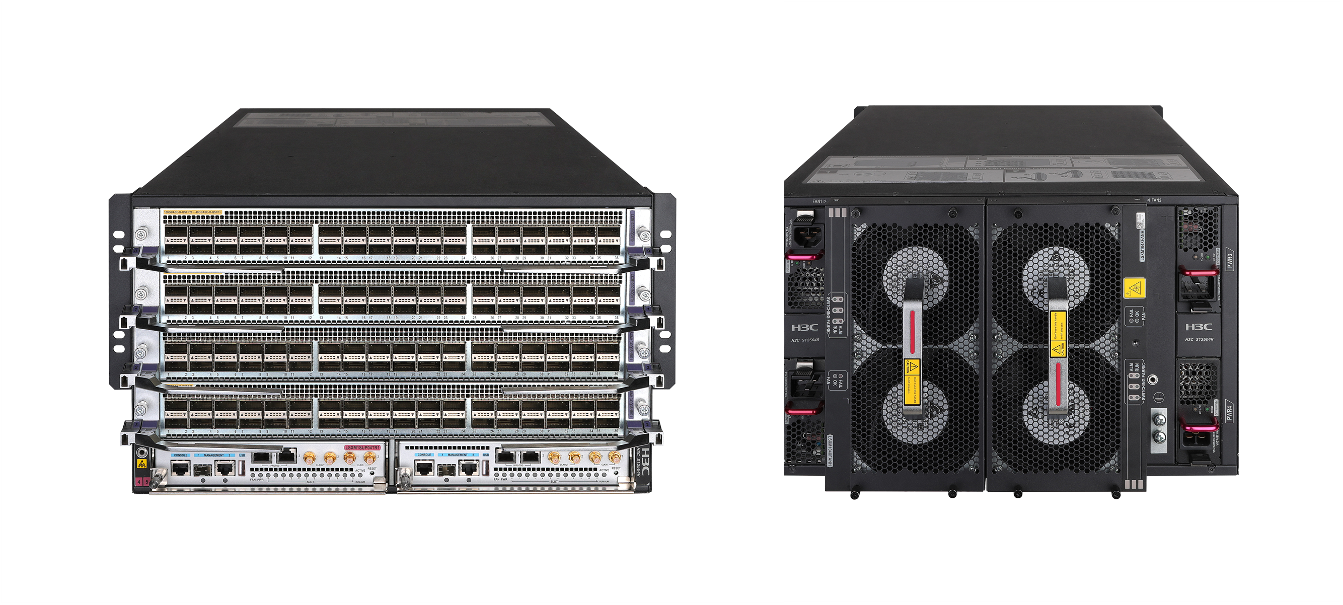
Figure 1-4 S12516CR
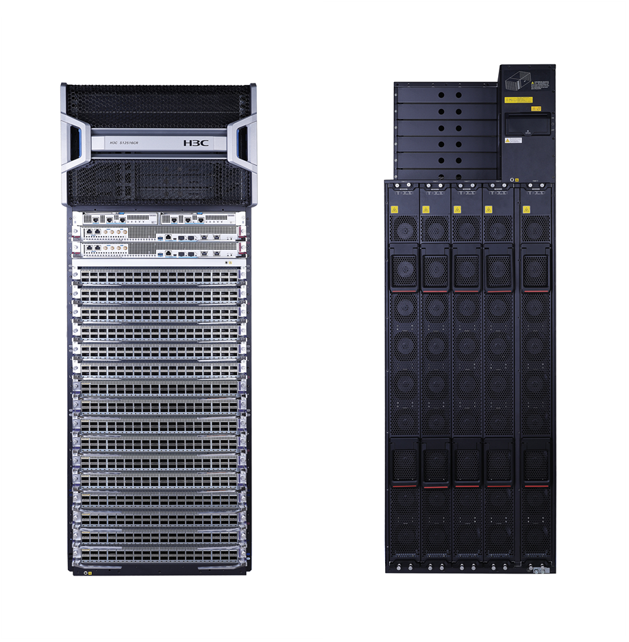
Figure 1-5 S12508CR
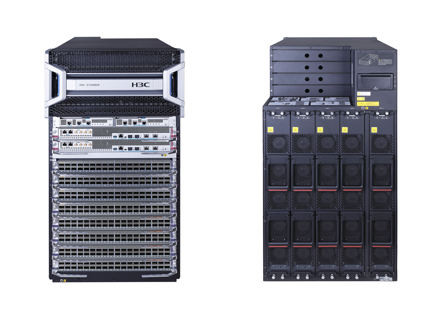
Figure 1-6 S12500R-2XL
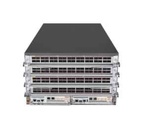
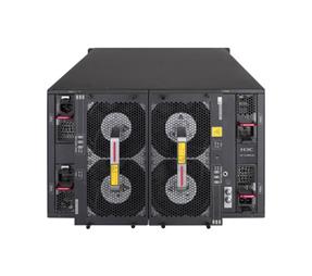
Figure 1-7 S12500R-2L
Chassis components
The device has a service module section, power module section, fan tray section, fabric module section, MPU section, and environment management module section. The S12500R-2XL and S12500R-2L use built-in fabric modules and do not have a fabric module section. Only the S12508CR and S12516CR have environment management module sections. The following figures use the S12500R-2L, S12516R, and S12516CR for illustration.
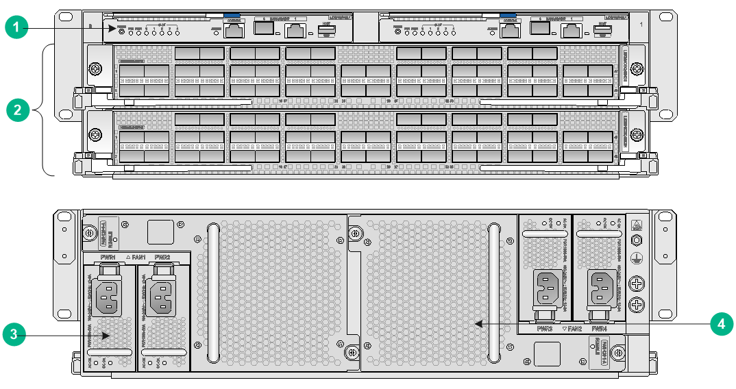
Figure 1-8 Front and rear views of the S12500R-2L
|
(1) SEU section |
(2) Interface module section |
|
(3) Power supply section |
(4) Fan tray section |
Table 1-1 Section descriptions for the S12500R-2L
|
Section |
Description |
|
SEU section (The SEU slot number and SEU module identifier are pink marked.) |
No SEUs are provided with the device. Purchase SEUs yourself. The device has two SEU slots. You can install one SEU, or two SEUs for redundancy. To install only one SEU for the device, you can install it in either of the SEU slots. |
|
Interface module section (The edges or ejector levers of the interface modules and the ejector lever pillow blocks on the interface module slots are purple marked.) |
No interface modules are provided with the device. Purchase interface modules yourself. The device has two interface module slots. You can install one or two interface modules for the device as needed. To install only one interface module for the device, you can install it in either of the interface module slots. |
|
Power supply section |
No power supplies are provided with the device. Purchase power supplies yourself. The device has four power supply slots, with two on each side of the chassis rear. The device supports N+N (dual power input lines) and N+1 (single power input line) power supply redundancy. Determine the number of power supplies based on the power supply mode and system power consumption. You can install a power supply in any of the empty power supply slots. |
|
Fan tray section (The fan tray section is at the rear of the chassis.) |
No fan trays are provided with the device. Purchase fan trays yourself. The device provides two fan tray slots FAN1 and FAN2. As a best practice, install two fan trays for redundancy. |
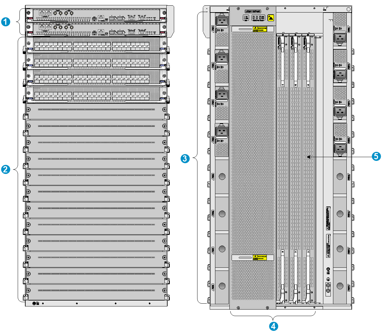
Figure 1-9 Front and rear views of the S12516R
|
(1) MPU section |
(2) Service module section |
(3) Power module section |
|
(4) Fan tray section |
(5) Fabric module section |
|
Table 1-2 Section description for the S12516R
|
Section |
Description |
|
MPU section · (S12516R and S12508R—Ejector levers of the MPUs and ejector lever pillow blocks on the MPU slots are pink marked. The MPU slots are above the service module slots. · S12504R—MPU slot numbers on the chassis and the names on the MPUs are pink marked. The MPU slots are below the service module slots.) |
No MPUs are provided with the device. Purchase MPUs yourself. The device has two MPU slots. You can install one MPU, or two MPUs for redundancy for the device. To install only one MPU for the device, you can install it in either of the MPU slots. |
|
Service module section (The edges or ejector levers of the service modules and the ejector lever pillow blocks on the service module slots are purple marked.) |
No service modules are provided with the device. Purchase service modules yourself. · S12516R—16 service module slots. · S12508R—8 service module slots. · S12504R—4 service module slots. You can install a service module in any of the empty service module slots. |
|
Power module section |
No power modules are provided with the device. Purchase power modules yourself. · S12516R—16 power module slots, with eight on each side of the chassis rear. · S12508R—8 power module slots, with four on each side of the chassis rear. · S12504R—4 power module slots, with two on each side of the chassis rear. The device supports N+N (dual power input lines) and N+1 (single power input line) power module redundancy. Determine the number of power modules based on power supply mode and the system power consumption. You can install a power module in any of the empty power module slots. |
|
Fan tray section (The fan tray section is at the rear of the chassis. Each fan tray covers three fabric module slots.) |
No fan trays are provided with the device. Purchase fan trays yourself. The device provides two fan tray slots FAN1 and FAN2. It can operate correctly with one fan tray. As a best practice, install two fan trays for redundancy. |
|
Fabric module section (Covered by the fan trays) |
No fabric modules or fabric module slot filler panels are provided with the device. Purchase fabric modules and fabric module slot filler panels yourself. · Configure two to six fabric modules for the device. Install filler panels in the empty fabric module slots. · The fabric module slots are covered by fan trays. To replace a fabric module, remove the fan tray above it. |
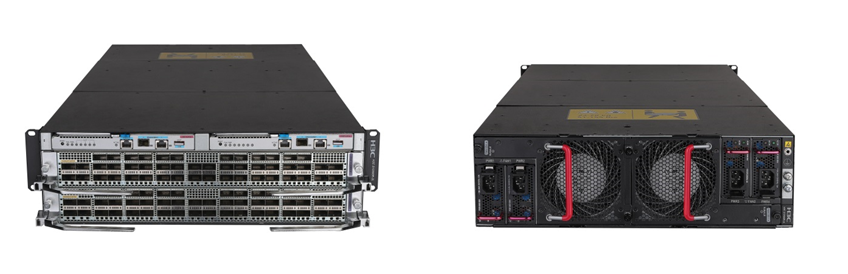
Figure 1-10 Front and rear views of the S12516CR
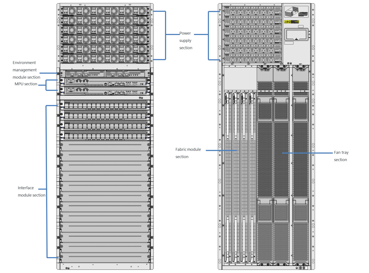
Table 1-3 Section description for the S12516CR
|
Section |
Description |
|
Power supply section |
No power trays or power supplies are provided with the device. Purchase power trays and power supplies yourself. · S12516CR—Six power tray slots. Each power tray has six power supply slots. Install a minimum of two power trays on an S12516CR. · S12508CR—Four power tray slots. Each power tray has six power supply slots. Install a minimum of one power tray on an S12508CR. The device supports N+N (dual power input lines) and N+1 (single power input line) power supply redundancy. Determine the number of power supplies based on power supply mode and the system power consumption. You can install a power supply in any of the empty power supply slots. |
|
Environment management module section |
No environment management modules are provided with the device. Purchase environment management modules yourself. The device has two environment management module slots and is shipped with an environment management module in each slot. |
|
MPU section (Ejector levers of the MPUs and ejector lever pillow blocks on the MPU slots are pink marked.) |
No MPUs are provided with the device. Purchase MPUs yourself. The device has two MPU slots. You can install one MPU, or two MPUs for redundancy. To install only one MPU for the device, you can install it in either of the MPU slots. |
|
Interface module section (The edges or ejector levers of the interface modules and the ejector lever pillow blocks on the interface module slots are purple marked.) |
No interface modules are provided with the device. Purchase interface modules yourself. · S12516CR—16 interface module slots. · S12508CR—8 interface module slots. You can install an interface module in any of the empty interface module slots. |
|
Fan tray section |
No fan trays are provided with the device. Purchase fan trays yourself. The device provides five fan tray slots. For adequate heat dissipation, make sure each fan tray slot has a fan tray installed. |
|
Fabric module section |
The device provides nine fabric module slots. No fabric modules are provided with the device. Purchase fabric modules yourself for the device as required. Before you remove a fabric module, remove the fan tray that covers it. |
Table 1-4 describes the slot arrangements for the removable components.
Table 1-4 Slot arrangement for the removable components
|
Model |
Environment management module |
MPU |
Service module |
Fabric module |
Power module |
Power tray |
Fan tray |
|
S12516R |
N/A |
Slots 0 and 1 |
Slots 2 to 17 |
Slots 18 to 23 · Slots 18 to 20 are covered by FAN 1. · Slots 21 to 23 are covered by FAN 2. |
PWR 1 to PWR 16 |
N/A |
FAN 1 and FAN 2 |
|
S12508R |
N/A |
Slots 0 and 1 |
Slots 2 to 9 |
Slots 10 to 15 · Slots 10 to 12 are covered by FAN 1. · Slots 13 to 15 are covered by FAN 2. |
PWR 1 to PWR 8 |
N/A |
FAN 1 and FAN 2 |
|
S12504R |
N/A |
Slots 4 and 5 |
Slots 0 to 3 |
Slots 6 to 11 · Slots 6 to 8 are covered by FAN 1. · Slots 9 to 11 are covered by FAN 2. |
PWR 1 to PWR 4 |
N/A |
FAN 1 and FAN 2 |
|
S12516CR |
Slots 0 and 1 |
Slots 2 and 3 |
Slots 4 to 19 |
Slots 20 to 28 · Slots 20 and 21 are covered by FAN 1. · Slots 22 and 23 are covered by FAN 2. · Slots 24 and 25 are covered by FAN 3. · Slots 26 and 27 are covered by FAN 4. · Slot 28 is covered by FAN 5. |
PWR 1 to PWR 6 |
PEM 1 to PEM 6 Each power tray provides six power supply slots PWR 1 to PWR 6. |
FAN 1 to FAN 5 |
|
S12508CR |
Slots 0 and 1 |
Slots 2 and 3 |
Slots 4 to 11 |
Slots 12 to 20 · Slots 12 and 13 are covered by FAN 1. · Slots 14 and 15 are covered by FAN 2. · Slots 16 and 17 are covered by FAN 3. · Slots 18 and 19 are covered by FAN 4. · Slot 20 is covered by FAN 5. |
PWR 1 to PWR 6 |
PEM 1 to PEM 4 Each power tray provides six power supply slots PWR 1 to PWR 6. |
FAN 1 to FAN 5 |
|
S12500R-2XL |
N/A |
Slots 2 and 3 |
Slots 0 and 1 |
Built-in fabric modules |
PWR 1 to PWR 4 |
N/A |
FAN 1 and FAN 2 |
|
S12500R-2L |
N/A |
Slots 0 and 1 |
Slots 2 and 3 |
Built-in fabric modules |
PWR 1 to PWR 4 |
N/A |
FAN 1 and FAN 2 |
Technical specifications
Weights and dimensions
Table 1-5 Chassis weights and dimensions
|
Model |
Weight |
Height |
Width |
Depth |
|
S12516R |
86.1 kg (189.81 lb) |
931 mm (36.65 in)/21 RU |
440 mm (17.32 in) |
857 mm (33.74 in) |
|
S12508R |
47.0 kg (103.62 lb) |
531 mm (20.91 in)/12 RU |
440 mm (17.32 in) |
857 mm (33.74 in) |
|
S12504R |
36.0 kg (79.37 lb) |
264 mm (10.39 in)/6 RU |
440 mm (17.32 in) |
857 mm (33.74 in) |
|
S12516CR |
111.6 kg (246.03 lb) |
1331 mm (52.40 in)/30 RU |
442 mm (17.40 in) |
920 mm (36.22 in) |
|
S12508CR |
82.4 kg (181.66 lb) |
842 mm (33.15 in)/19 RU |
442 mm (17.40 in) |
920 mm (36.22 in) |
|
S12500R-2L |
22.6 kg (49.82 lb) |
133 mm (5.24 in)/3 RU |
440 mm (17.32 in) |
895 mm (35.24 in) |
|
S12500R-2XL |
46.8 kg (103.17 lb) |
264 mm (10.39 in)/6 RU |
440 mm (17.32 in) |
857 mm (33.74 in) |
|
|
NOTE: · Rack height is measured in RUs. One RU is 44.45 mm (1.75 in). · Table 1-5 lists dimensions for the device, excluding the mounting brackets, cable management brackets, modules, and power modules. |
Table 1-6 Module weights and dimensions
|
Model |
Weight |
Height |
Width |
Depth |
|
LSXM1SUPER1 |
6.2 kg (13.67 lb) |
43.7 mm (1.72 in) |
432.6 mm (17.03 in) |
511.7 mm (20.15 in) |
|
LSXM1SUPEAR1 |
6.4 kg (14.11 lb) |
43.7 mm (1.72 in) |
432.6 mm (17.03 in) |
511.7 mm (20.15 in) |
|
LSXM1SUPKR1 |
6.6 kg (14.55 lb) |
43.7 mm (1.72 in) |
446.4 mm (17.57 in) |
519.8 mm (20.46 in) |
|
LSXM1SUPKAR1 |
6.6 kg (14.55 lb) |
43.7 mm (1.72 in) |
446.4 mm (17.57 in) |
519.8 mm (20.46 in) |
|
LSXM1SUPRS2 |
6.6 kg (14.55 lb) |
43.7 mm (1.72 in) |
446.4 mm (17.57 in) |
519.8 mm (20.46 in) |
|
LSXM1SUP02LR1 |
2.1 kg (4.63 lb) |
22.5 mm (0.89 in) |
193.0 mm (7.60 in) |
364.3 mm (14.34 in) |
|
LSXM1SUP04TR1 |
2.7 kg (5.95 lb) |
39.8 mm (1.57 in) |
200.5 mm (7.89 in) |
411.0 mm (16.18 in) |
|
LSXM2SFH16CR1 |
7.9 kg (17.42 lb) |
39.8 mm (1.57 in) |
853.0 mm (33.58 in) |
278.4 mm (10.96 in) |
|
LSXM1SFH16ER1 |
9.7 kg (21.38 lb) |
39.8 mm (1.57 in) |
853.0 mm (33.58 in) |
278.4 mm (10.96 in) |
|
LSXM1SFH08CR1 |
4.6 kg (10.14 lb) |
39.8 mm (1.57 in) |
453.0 mm (17.83 in) |
278.4 mm (10.96 in) |
|
LSXM1SFH08DR1 |
4.9 kg (10.80 lb) |
39.8 mm (1.57 in) |
453.0 mm (17.83 in) |
278.4 mm (10.96 in) |
|
LSXM1SFH04DR1 |
2.8 kg (6.17 lb) |
39.8 mm (1.57 in) |
243.0 mm (9.57 in) |
278.4 mm (10.96 in) |
|
LSXM1SFK16ER1 |
10.0 kg (22.05 lb) |
39.8 mm (1.57 in) |
853.0 mm (33.58 in) |
278.4 mm (10.96 in) |
|
LSXM1SFK16GR1 |
11.3 kg (24.91 lb) |
39.8 mm (1.57 in) |
853.0 mm (33.58 in) |
278.4 mm (10.96 in) |
|
LSXM1SFK08ER1 |
4.8 kg (10.58 lb) |
39.8 mm (1.57 in) |
453.0 mm (17.83 in) |
278.4 mm (10.96 in) |
|
LSXM1SFK08FR1 |
5.7 kg (12.57 lb) |
39.8 mm (1.57 in) |
453.0 mm (17.83 in) |
278.4 mm (10.96 in) |
|
LSXM1SFK08GR1 |
5.9 kg (13.01 lb) |
39.8 mm (1.57 in) |
453.0 mm (17.83 in) |
278.4 mm (10.96 in) |
|
LSXM1SFK04FR1 |
3.0 kg (6.67 lb) |
39.8 mm (1.57 in) |
243.0 mm (9.57 in) |
278.4 mm (10.96 in) |
|
LSXM3SFS16F2 |
9.4 kg (20.72 lb) |
39.8 mm (1.57 in) |
853.0 mm (33.58 in) |
278.4 mm (10.96 in) |
|
LSXM3SFS16G2 |
10.2 kg (22.49 lb) |
39.8 mm (1.57 in) |
853.0 mm (33.58 in) |
278.4 mm (10.96 in) |
|
LSXM3SFS08F2 |
4.5 kg (9.92 lb) |
39.8 mm (1.57 in) |
453.0 mm (17.83 in) |
278.4 mm (10.96 in) |
|
LSXM3SFS08G2 |
5.1 kg (11.24 lb) |
39.8 mm (1.57 in) |
453.0 mm (17.83 in) |
278.4 mm (10.96 in) |
|
LSXM1CCQ48KBR1 |
10.5 kg (23.15 lb) |
50.0 mm (1.97 in) |
432.6 mm (17.03 in) |
519.8 mm (20.46 in) |
|
LSXM1CDMS36KCR1 |
11.8 kg (26.01 lb) |
50.0 mm (1.97 in) |
446.4 mm (17.57 in) |
519.8 mm (20.46 in) |
|
LSXM1CDQ24KBR1 |
10.0 kg (22.05 lb) |
50.0 mm (1.97 in) |
432.6 mm (17.03 in) |
519.8 mm (20.46 in) |
|
LSXM1CDQ36KBR1 |
13.1 kg (28.88 lb) |
50.0 mm (1.97 in) |
446.4 mm (17.57 in) |
519.8 mm (20.46 in) |
|
LSXM1CGMS48KBR1 |
9.7 kg (21.38 lb) |
50.0 mm (1.97 in) |
432.6 mm (17.03 in) |
519.8 mm (20.46 in) |
|
LSXM1CGQFX16KBR1 |
10.6 kg (23.37 lb) |
50.0 mm (1.97 in) |
432.6 mm (17.03 in) |
519.8 mm (20.46 in) |
|
LSXM1CGQ36HBR1 |
11.1 kg (24.47 lb) |
50.0 mm (1.97 in) |
432.6 mm (17.03 in) |
519.8 mm (20.46 in) |
|
LSXM1CGQ36HFR1 |
12.3 kg (27.12 lb) |
50.0 mm (1.97 in) |
432.6 mm (17.03 in) |
519.8 mm (20.46 in) |
|
LSXM1CGQ48KBR1 |
9.3 kg (20.50 lb) |
50.0 mm (1.97 in) |
432.6 mm (17.03 in) |
519.8 mm (20.46 in) |
|
LSXM1CGQ72KCR1 |
14.7 kg (32.41 lb) |
100.8 mm (3.97 in) |
432.6 mm (17.03 in) |
519.8 mm (20.46 in) |
|
LSXM1TGS48HFR1 |
7.6 kg (16.75 lb) |
50.0 mm (1.97 in) |
432.6 mm (17.03 in) |
519.8 mm (20.46 in) |
|
LSXM1CGQ18QGHFR1 |
9.0 kg (19.84 lb) |
50.0 mm (1.97 in) |
432.6 mm (17.03 in) |
519.8 mm (20.46 in) |
|
LSXM1CGQ6QGHFR1 |
7.3 kg (16.09 lb) |
50.0 mm (1.97 in) |
432.6 mm (17.03 in) |
519.8 mm (20.46 in) |
|
LSXM1TGS48HBR1 |
7.5 kg (16.53 lb) |
50.0 mm (1.97 in) |
432.6 mm (17.03 in) |
519.8 mm (20.46 in) |
|
LSXM1CGQ18QGHBR1 |
8.3 kg (18.30 lb) |
50.0 mm (1.97 in) |
432.6 mm (17.03 in) |
519.8 mm (20.46 in) |
|
LSXM1MOD24KBR1 |
7.4 kg (16.31 lb) |
50.0 mm (1.97 in) |
432.6 mm (17.03 in) |
519.8 mm (20.46 in) |
|
LSXM3CDQ16SF2 |
8.9 kg (19.62 lb) |
50.0 mm (1.97 in) |
432.6 mm (17.03 in) |
519.8 mm (20.46 in) |
|
LSXM3CDQ8SF2 |
8.5 kg (18.74 lb) |
50.0 mm (1.97 in) |
432.6 mm (17.03 in) |
519.8 mm (20.46 in) |
|
LSXM3CGQ36SF2 |
8.6 kg (18.96 lb) |
50.0 mm (1.97 in) |
432.6 mm (17.03 in) |
519.8 mm (20.46 in) |
|
LSXM3CGQ18SF2 |
7.4 kg (16.31 lb) |
50.0 mm (1.97 in) |
432.6 mm (17.03 in) |
519.8 mm (20.46 in) |
|
LSXM3QGS36SF2 |
7.7 kg (16.98 lb) |
50.0 mm (1.97 in) |
432.6 mm (17.03 in) |
519.8 mm (20.46 in) |
|
LSXM3YGS48SF2 |
7.2 kg (15.87 lb) |
50.0 mm (1.97 in) |
432.6 mm (17.03 in) |
519.8 mm (20.46 in) |
|
LSXM3TGS48SF2 |
7.2 kg (15.87 lb) |
50.0 mm (1.97 in) |
432.6 mm (17.03 in) |
519.8 mm (20.46 in) |
|
LSXM1CMUR1 |
2.5 kg (5.51 lb) |
32.0 mm (1.26 in) |
192.0 mm (7.56 in) |
396.9 mm (15.63 in) |
|
LSXM1CMURS2 |
2.5 kg (5.51 lb) |
32.0 mm (1.26 in) |
192.0 mm (7.56 in) |
396.9 mm (15.63 in) |
|
|
NOTE: Module dimensions are expressed as follows: · Height—Height of the front panel of the module. · Width—Width of the front panel of the module. · Depth—Depth from the front panel of the module to the connector (Including the connector, but excluding the ejector levers and captive screws). |
Table 1-7 Weights and dimensions of the interface modules
|
Model |
Weight |
Height |
Width |
Depth |
|
LSXM1CGQ18C1 |
1.78 kg (3.92 lb) |
44.0 mm (1.73 in) |
191.0 mm (7.52 in) |
271.0 mm (10.67 in) |
|
LSXM1CGQ8C1 |
1.50 kg (3.31 lb) |
44.0 mm (1.73 in) |
191.0 mm (7.52 in) |
271.0 mm (10.67 in) |
|
LSXM1TGS24C1 |
1.53 kg (3.37 lb) |
44.0 mm (1.73 in) |
191.0 mm (7.52 in) |
271.0 mm (10.67 in) |
Table 1-8 Weights and dimensions of the fabric module slot filler panels
|
Model |
Weight |
Height |
Width |
Depth |
|
S12516R fabric module slot filler panel |
2.8 kg (6.17 lb) |
39.8 mm (1.57 in) |
853.6 mm (33.60 in) |
136.0 mm (5.35 in) |
|
S12508R fabric module slot filler panel |
1.6 kg (3.53 lb) |
40.0 mm (1.57 in) |
453.0 mm (17.83 in) |
133.0 mm (5.24 in) |
|
S12504R fabric module slot filler panel |
0.9 kg (1.98 lb) |
40.0 mm (1.57 in) |
243.0 mm (9.57 in) |
136.0 mm (5.35 in) |
|
S12516CR fabric module slot filler panel |
2.8 kg (6.17 lb) |
39.8 mm (1.57 in) |
853.0 mm (33.58 in) |
289.0 mm (11.38 in) |
|
S12508CR fabric module slot filler panel |
1.6 kg (3.53 lb) |
39.8 mm (1.57 in) |
453.0 mm (17.83 in) |
289.0 mm (11.38 in) |
Table 1-9 Power tray weights and dimensions
|
Model |
Net weight |
Height |
Width |
Depth |
|
CR-PEM-DC2000 |
7.3 kg (16.09 lb) |
46.7 mm (1.84 in) |
437.5 mm (17.22 in) |
750 mm (29.53 in) |
|
CR-PEM-AC3000 |
6.7 kg (14.77 lb) |
46.7 mm (1.84 in) |
437.5 mm (17.22 in) |
750 mm (29.53 in) |
|
CR-PEM-HVDC3000 |
6.7 kg (14.77 lb) |
46.7 mm (1.84 in) |
437.5 mm (17.22 in) |
750 mm (29.53 in) |
Table 1-10 Power module weights and dimensions
|
Model |
Weight |
Height |
Width |
Depth |
|
PSR1800-56A |
1.6 kg (3.53 lb) |
40.1 mm (1.58 in) |
82.6 mm (3.25 in) |
297.7 mm (11.72 in) |
|
PSR1800-56D |
2.0 kg (4.41 lb) |
40.1 mm (1.58 in) |
82.6 mm (3.25 in) |
297.7 mm (11.72 in) |
|
PSR2400-54A |
1.9 kg (4.19 lb) |
100.0 mm (3.93 in) |
332.0 mm (13.07 in) |
|
|
PSR2400-54D |
1.9 kg (4.19 lb) |
41.0 mm (1.61 in) |
100.0 mm (3.93 in) |
332.0 mm (13.07 in) |
|
PSR3000-54A |
2.1 kg (4.63 lb) |
41.0 mm (1.61 in) |
100.0 mm (3.93 in) |
332.0 mm (13.07 in) |
|
PSR3000-54AHD |
2.1 kg (4.63 lb) |
41.0 mm (1.61 in) |
100.0 mm (3.93 in) |
332.0 mm (13.07 in) |
|
PSR2000B-54D |
2.0 kg (4.41 lb) |
40.5 mm (1.59 in) |
68.0 mm (2.68 in) |
450.0 mm (17.72 in) |
|
PSR3000B-54AHD |
2.0 kg (4.41 lb) |
40.5 mm (1.59 in) |
68.0 mm (2.68 in) |
450.0 mm (17.72 in) |
Table 1-11 Fan tray weights and dimensions
|
Model |
Weight |
Height |
Width |
Depth |
|
S12516R fan tray—LSXM116XFAN |
6.7 kg (14.77 lb) |
144.0 mm (5.67 in) |
927.0 mm (36.50 in) |
183.0 mm (7.20 in) |
|
S12516R fan tray —LSXM116XFANH |
8.4 kg (18.52 lb) |
144.0 mm (5.67 in) |
927.0 mm (36.50 in) |
183.0 mm (7.20 in) |
|
S12508R fan tray—LSXM108XFAN |
3.8 kg (8.38 lb) |
144.0 mm (5.67 in) |
527.0 mm (20.75 in) |
183.0 mm (7.20 in) |
|
S12508R fan tray—LSXM108XFANH |
4.4 kg (9.70 lb) |
144.0 mm (5.67 in) |
527.0 mm (20.75 in) |
183.0 mm (7.20 in) |
|
S12504R fan tray—LSXM104XFAN |
1.8 kg (3.97 lb) |
144.0 mm (5.67 in) |
263.0 mm (10.35 in) |
97.0 mm (3.82 in) |
|
S12504R fan tray—LSXM104XFANH |
3.0 kg (6.61 lb) |
144.0 mm (5.67 in) |
263.0 mm (10.35 in) |
136.0 mm (5.35 in) |
|
S12500R-2XL fan tray—LSXM104XFANH |
3.0 kg (6.61 lb) |
144.0 mm (5.67 in) |
263.0 mm (10.35 in) |
136.0 mm (5.35 in) |
|
S12516CR fan tray—FAN-80-9-A |
8.4 kg (18.52 lb) |
1100.0 mm (43.31 in) |
80.4 mm (3.17 in) |
183.2 mm (7.21 in) |
|
S12508CR fan tray—FAN-80-5-A |
5.1 kg (11.24 lb) |
601.3 mm (23.67 in) |
80.4 mm (3.17 in) |
183.2 mm (7.21 in) |
|
S12500R-2L fan tray—FAN-120-1-A |
1.6 kg (3.53 lb) |
123.0 mm (4.84 in) |
214.0 mm (8.43 in) |
123.0 mm (4.84 in) |
Module power consumption and system power consumption
Module power consumption
The power consumption varies by module model and state. Table 1-12 shows the power consumption for different module models.
· The static power consumption of a module refers to the power consumed by the module when module is running but all ports on the module are down and when no transceiver module is available on the optical interface of the module.
· The dynamic power consumption of a module refers to the power consumed by the module when all the ports on the module are link up and send broadcasts.
Table 1-12 Module power consumption
|
Model |
Minimum static power consumption |
Typical power consumption |
Maximum dynamic power consumption |
|
LSXM1SUPER1 |
52 W |
52 W |
70 W |
|
LSXM1SUPEAR1 |
55 W |
55 W |
65 W |
|
LSXM1SUPKR1 |
50 W |
50 W |
60 W |
|
LSXM1SUPKAR1 |
60 W |
60 W |
70 W |
|
LSXM1SUPRS2 |
50 W |
50 W |
60 W |
|
LSXM1SUP02LR1 |
28 W |
28 W |
35 W |
|
LSXM1SUP04TR1 |
24 W |
24 W |
35 W |
|
LSXM2SFH16CR1 |
194 W |
281 W |
308 W |
|
LSXM1SFH16ER1 |
487 W |
752 W |
816 W |
|
LSXM1SFH08CR1 |
84 W |
117 W |
135 W |
|
LSXM1SFH08DR1 |
159 W |
231 W |
255 W |
|
LSXM1SFH04DR1 |
86 W |
124 W |
140 W |
|
LSXM1SFK16ER1 |
159 W |
226 W |
293 W |
|
LSXM1SFK16GR1 |
471 W |
647 W |
822 W |
|
LSXM1SFK08ER1 |
90 W |
146 W |
157 W |
|
LSXM1SFK08FR1 |
160 W |
322 W |
284 W |
|
LSXM1SFK08GR1 |
206 W |
277 W |
366 W |
|
LSXM1SFK04FR1 |
104 W |
147 W |
212 W |
|
LSXM3SFS16F2 |
123 W |
172 W |
257 W |
|
LSXM3SFS16G2 |
241 W |
317 W |
500 W |
|
LSXM3SFS08F2 |
68 W |
86 W |
124 W |
|
LSXM3SFS08G2 |
137 W |
176 W |
259 W |
|
LSXM1CCQ48KBR1 |
412 W |
564 W |
1142 W |
|
LSXM1CDMS36KCR1 |
485 W |
785 W |
1710 W |
|
LSXM1CDQ24KBR1 |
469 W |
696 W |
1020 W |
|
LSXM1CDQ36KBR1 |
739.2 W |
1130 W |
1869 W |
|
LSXM1CGMS48KBR1 |
525 W |
675 W |
1040 W |
|
LSXM1CGQFX16KBR1 |
330 W |
385 W |
485 W |
|
LSXM1CGQ36HBR1 (*) |
608 W |
662 W |
1070 W |
|
LSXM1CGQ36HFR1 (*) |
585 W |
819 W |
1100 W |
|
LSXM1CGQ48KBR1 |
395 W |
447 W |
765 W |
|
LSXM1CGQ72KCR1 |
530 W |
635 W |
980 W |
|
LSXM1TGS48HFR1 |
136 W |
161 W |
230 W |
|
LSXM1CGQ18QGHFR1 |
316 W |
425 W |
650 W |
|
LSXM1CGQ6QGHFR1 |
132 W |
171 W |
325 W |
|
LSXM1TGS48HBR1 |
111 W |
127 W |
210 W |
|
LSXM1CGQ18QGHBR1 |
256 W |
326 W |
525 W |
|
LSXM1MOD24KBR1 |
135 W |
350 W |
577 W |
|
LSXM3CDQ16SF2 |
260 W |
365 W |
679 W |
|
LSXM3CDQ8SF2 |
258 W |
320 W |
542 W |
|
LSXM3CGQ36SF2 |
252 W |
328 W |
587 W |
|
LSXM3CGQ18SF2 |
144 W |
194 W |
311 W |
|
LSXM3QGS36SF2 |
140 W |
188 W |
356 W |
|
LSXM3YGS48SF2 |
101 W |
118 W |
234 W |
|
LSXM3TGS48SF2 |
95 W |
101 W |
175 W |
|
LSXM1CMUR1 |
22 W |
22 W |
26 W |
|
LSXM1CMURS2 |
22 W |
22 W |
26 W |
|
|
IMPORTANT: High-performance fan trays are required when the device uses the interface modules marked by (*) in the preceding table. For information about high-performance fan trays, see "Fan trays". |
Interface module power consumption
Table 1-13 Interface module power consumption
|
Interface module model |
Minimum power consumption |
Typical power consumption |
Maximum power consumption |
|
LSXM1CGQ18C1 |
90 W |
101 W |
169 W |
|
LSXM1CGQ8C1 |
38 W |
49 W |
79 W |
|
LSXM1TGS24C1 |
33 W |
35 W |
63 W |
Fan tray power consumption
The device uses fan trays that can automatically adjust the fan speed based on the device temperature. The power consumed by a fan tray depends on the fan speed.
Table 1-14 Fan tray power consumption
|
Device model |
Fan tray model |
Minimum power consumption |
Typical power consumption |
Maximum power consumption |
|
S12516R |
LSXM116XFAN |
33 W |
206 W |
793 W |
|
LSXM116XFANH |
187 W |
675 W |
2570 W |
|
|
S12508R |
LSXM108XFAN |
17 W |
103 W |
395 W |
|
LSXM108XFANH |
86 W |
317 W |
1239 W |
|
|
S12504R |
LSXM104XFAN |
14 W |
66 W |
255 W |
|
S12504R |
LSXM104XFANH |
19.4 W |
87 W |
588 W |
|
S12500R-2XL |
LSXM104XFANH |
19.4 W |
87 W |
588 W |
|
S12516CR |
FAN-80-9-A |
54 W |
202 W |
1105 W |
|
S12508CR |
FAN-80-5-A |
27 W |
110 W |
590 W |
|
S12500R-2L |
FAN-120-1-A |
17 W |
31 W |
269 W |
System power consumption
The system power consumption of the device depends on the type and number of modules and the fan tray power consumption.
· The minimum system power consumption is the total static power consumption of all modules plus the minimum fan tray power consumption.
· The maximum system power consumption is the total dynamic power consumption of all modules plus the maximum fan tray power consumption.
For example, for an S12516CR that has two LSXM1SUPKR1 MPUs, two LSXM1CMUR1 environment management modules, two LSXM1CGQ48KBR1 interface modules, six LSXM1SFK16GR1 fabric modules, and five FAN-80-9-A fan trays, the minimum system power consumption of the device is 2 × 50 + 2 × 22 + 2 × 395 + 6 × 471 + 5 × 54 = 4030 W. The maximum system power consumption of the device is 2 × 60 + 2 × 26 + 2 × 765 + 6 × 822 + 5 × 1105 = 12159 W.
Heat dissipation
Heat dissipation is measured in BTU/h, and 1 W equals 3.4121 BTU/h.
The heat dissipation of a device depends on its power consumption. To calculate heat dissipation of the device, assume 90% power consumption is converted to heat, and the efficiency of the power module is 90%. Heat dissipation/hour of the device is 0.9 × (total power consumption of the modules plus power consumption of the fan tray)/0.9 × 3.4121.
For the power consumption of the modules and fan trays, see "Module power consumption and system power consumption."
Environmental specifications
Table 1-15 Environmental specifications
|
Description |
Operating |
Non-operating |
|
Temperature |
0°C to 40°C (32°F to 104°F) |
–40°C to +70°C (–40°F to +158°F) |
|
Relative humidity (noncondensing) |
5% to 95% |
5% to 95% |
Chassis ordering information
To purchase an S12500R chassis, contact the sales agent or H3C sales personnel.
Table 1-16 S12500R chassis ordering information
|
Product code |
Product name |
Description |
|
0235A2FL |
S12516R |
H3C S12516R Ethernet switch router chassis |
|
0235A2FN |
S12508R |
H3C S12508R Ethernet switch router chassis |
|
0235A2FM |
S12504R |
H3C S12504R Ethernet switch router chassis |
|
0235A2JU |
S12516CR |
H3C S12516CR Ethernet switch router chassis |
|
0235A2JT |
S12508CR |
H3C S12508CR Ethernet switch router chassis |
|
0235A2JM |
S12500R-2L |
H3C S12500R-2L Ethernet switch router chassis |
|
0235A2TG |
S12500R-2XL |
H3C S12500R-2XL Ethernet switch router chassis |
