- Table of Contents
- Related Documents
-
| Title | Size | Download |
|---|---|---|
| 02-Hardware Information and Specifications | 2.94 MB |
Product models and technical specifications
1/10GBASE-T autosensing Ethernet port
1/10GBASE-T autosensing Ethernet port LEDs
Product models and technical specifications
Product models
H3C S6861 switch series includes the S6861-54QF, S6861-54QT, and S6861-30QF models.
Technical specifications
Table 1 Technical specifications
|
Item |
S6861-54QF |
S6861-30QF |
S6861-54QT |
|
|
Part number in BOM |
0235A3GL |
0235A3GJ |
0235A3GK |
|
|
Product code |
LS-6861-54QF |
LS-6861-30QF |
LS-6861-54QT |
|
|
Dimensions (H × W × D) |
44 × 440 × 400 mm (1.73 × 17.32 × 15.75 in) |
44 × 440 × 400 mm (1.73 × 17.32 × 15.75 in) |
44 × 440 × 460 mm (1.73 × 17.32 × 18.11 in) |
|
|
Weight |
≤ 10 kg (22.05 lb) |
≤ 10 kg (22.05 lb) |
≤ 10 kg (22.05 lb) |
|
|
Console ports |
· 1 × mini USB console port · 1 × serial console port |
· 1 × mini USB console port · 1 × serial console port |
· 1 × mini USB console port · 1 × serial console port |
|
|
Management Ethernet ports |
· 1 × 10M/100M/1000MBASE-T copper port · 1 × SFP port |
· 1 × 10M/100M/1000MBASE-T copper port · 1 × SFP port |
· 1 × 10M/100M/1000MBASE-T copper port · 1 × SFP port |
|
|
USB ports |
1 |
1 |
1 |
|
|
1/10GBASE-T autosensing Ethernet ports |
N/A |
N/A |
48 |
|
|
SFP+ ports |
48 |
24 |
N/A |
|
|
QSFP+ ports |
6 |
6 |
6 |
|
|
Fan tray slots |
4 |
4 |
5 |
|
|
Power module slots |
2 |
2 |
2 |
|
|
Input voltage |
PSR250-12A/PSR250-12A1: · AC input ¡ Rated voltage: 100 to 240 VAC @ 50/60 Hz ¡ Max voltage: 90 to 290 VAC @ 47 to 63 Hz · High-voltage DC input ¡ Rated voltage: 240 VDC ¡ Max voltage: 180 to 320 VDC PSR450-12A/PSR450-12A1: · AC input ¡ Rated voltage: 100 to 240 VAC @ 50/60 Hz ¡ Max voltage: 90 to 290 VAC @ 47 to 63 Hz · High-voltage DC input ¡ Rated voltage: 240 VDC ¡ Max voltage: 180 to 320 VDC PSR450-12AHD: · AC input ¡ Rated voltage: 100 to 240 VAC @ 50/60 Hz ¡ Max voltage: 90 to 290 VAC @ 47 to 63 Hz · High-voltage DC input ¡ Rated voltage: 240 to 380 VDC ¡ Max voltage: 180 to 400 VDC PSR450-12D: · Rated voltage: –48 to –60 VDC · Max voltage: –36 to –72 VDC |
PSR450-12A/PSR450-12A1: · AC input ¡ Rated voltage: 100 to 240 VAC @ 50/60 Hz ¡ Max voltage: 90 to 290 VAC @ 47 to 63 Hz · High-voltage DC input ¡ Rated voltage: 240 VDC ¡ Max voltage: 180 to 320 VDC PSR450-12AHD: · AC input ¡ Rated voltage: 100 to 240 VAC @ 50/60 Hz ¡ Max voltage: 90 to 290 VAC @ 47 to 63 Hz · High-voltage DC input ¡ Rated voltage: 240 to 380 VDC ¡ Max voltage: 180 to 400 VDC PSR450-12D: · Rated voltage: –48 to –60 VDC · Max voltage: –36 to –72 VDC |
||
|
Minimum power consumption |
PSR250-12A/PSR250-12A1: · Single AC input: 66 W · Dual AC inputs: 74 W PSR450-12A/PSR450-12A1: · Single AC input: 68 W · Dual AC inputs: 76 W PSR450-12AHD: · Single DC input: 65 W · Dual DC inputs: 73 W PSR450-12D: · Single DC input: 68 W · Dual DC inputs: 73 W |
PSR250-12A/PSR250-12A1: · Single AC input: 66 W · Dual AC inputs: 74 W PSR450-12A/PSR450-12A1: · Single AC input: 67 W · Dual AC inputs: 76 W PSR450-12AHD: · Single DC input: 65 W · Dual DC inputs: 73 W PSR450-12D: · Single DC input: 68 W · Dual DC inputs: 74 W |
PSR450-12A/PSR450-12A1 · Single AC input: 101 W · Dual AC inputs: 108 W PSR450-12AHD: · Single DC input: 95 W · Dual DC inputs: 105 W PSR450-12D: · Single DC input: 97 W · Dual DC inputs: 104 W |
|
|
Maximum power consumption |
PSR250-12A/PSR250-12A1: · Single AC input: 171 W · Dual AC inputs: 178 W PSR450-12A/PSR450-12A1: · Single AC input: 169 W · Dual AC inputs: 178 W PSR450-12AHD: · Single DC input: 166 W · Dual DC inputs: 173 W PSR450-12D: · Single DC input: 169 W · Dual DC inputs: 176 W |
PSR250-12A/PSR250-12A1: · Single AC input: 130 W · Dual AC inputs: 134 W PSR450-12A/PSR450-12A1: · Single AC input: 130 W · Dual AC inputs: 138 W PSR450-12AHD: · Single DC input: 131 W · Dual DC inputs: 139 W PSR450-12D: · Single DC input: 133 W · Dual DC inputs: 140 W |
PSR450-12A/PSR450-12A1: · Single AC input: 255 W · Dual AC inputs: 258 W PSR450-12AHD: · Single DC input: 254 W · Dual DC inputs: 261 W PSR450-12D: · Single DC input: 259 W · Dual DC inputs: 264 W |
|
|
Chassis leakage current compliance |
UL60950-1/EN60950-1/IEC60950-1/GB4943 |
|||
|
Melting current of power module fuse |
PSR250-12A/PSR250-12A1: 6.3 A @ 250 VAC PSR450-12A/PSR450-12A1: 10 A @ 250 VAC PSR450-12D: 20 A @ 125 V PSR450-12AHD: 10 A @ 420 V |
PSR450-12A/PSR450-12A1: 10 A @ 250 VAC PSR450-12D: 20 A @ 125 V PSR450-12AHD: 10 A @ 420 V |
||
|
Operating temperature |
0°C to 45°C (32°F to 113°F) |
|||
|
Operating humidity |
10% RH to 90% RH, noncondensing |
|||
|
Fire resistance compliance |
UL60950-1/EN60950-1/IEC60950-1/GB4943 |
|||
Chassis views
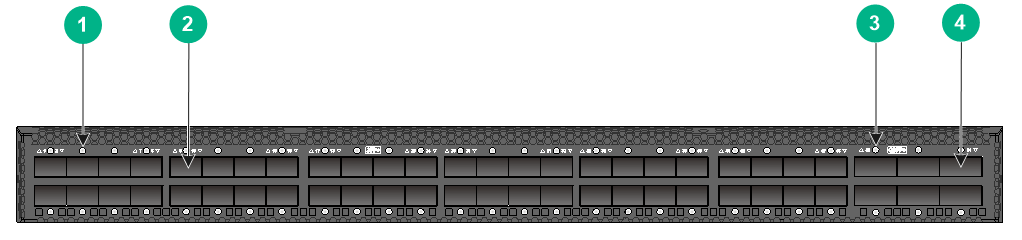
S6861-54QF
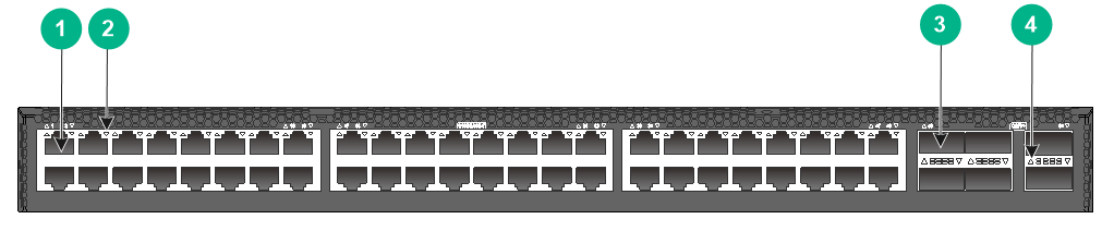
Figure 1 Front panel
|
(1) SFP+ port LED |
(2) SFP+ port |
|
(3) QSFP+ port LED |
(4) QSFP+ port |
|
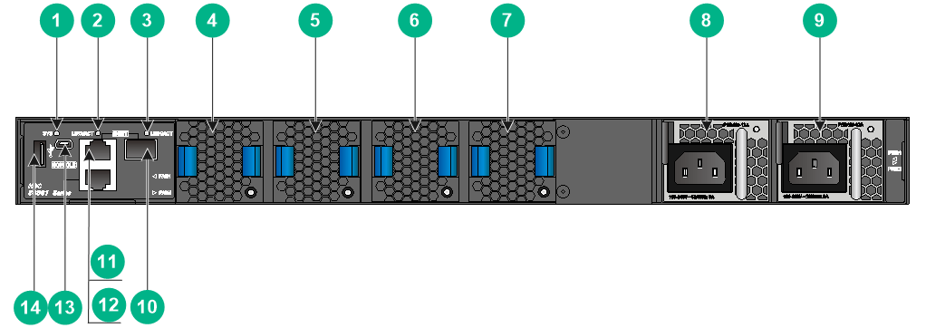
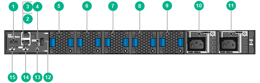
(1) System status LED (SYS) |
(2) LINK/ACT LED for the copper management Ethernet port |
|
(3) LINK/ACT LED for the fiber management Ethernet port |
(4) Fan tray 1 |
|
(5) Fan tray 2 |
(6) Fan tray 3 |
|
(7) Fan tray 4 |
(8) Power module 1 |
|
(9) Power module 2 |
(10) Fiber management Ethernet port |
|
(11) Copper management Ethernet port |
(12) Console port |
|
(13) Mini USB console port |
(14) USB port |
An S6861-54QF switch comes with power module slot PWR1 empty and power module slot PWR2 installed with a filler panel. In Figure 2, two PSR450-12A power modules are installed in the power module slots.
An S6861-54QF switch comes with the four fan tray slots empty. You must install four fan trays of the same model for the switch. In Figure 2, four LSPM1FANSA fan trays are installed in the fan tray slots.
|
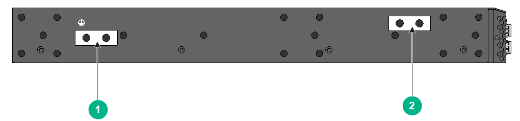
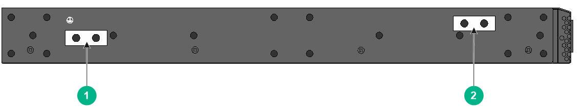
(1) Primary grounding point |
(2) Auxiliary grounding point |
S6861-54QT
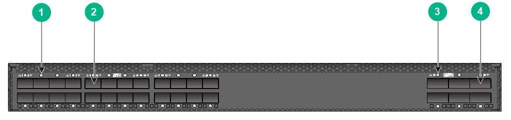
Figure 4 Front panel
|
(1) 1/10GBASE-T autosensing Ethernet port |
(2) 1/10GBASE-T autosensing Ethernet port LED |
|
(3) QSFP+ port |
(4) QSFP+ port LED |
|
(1) Fiber management Ethernet port |
(2) Copper management Ethernet port |
|
(3) Console port |
(4) Mini USB console port |
|
(5) Fan tray 1 |
(6) Fan tray 2 |
|
(7) Fan tray 3 |
(8) Fan tray 4 |
|
(9) Fan tray 5 |
(10) Power module 1 |
|
(11) Power module 2 |
(12) USB port |
|
(13) System status LED (SYS) |
(14) LINK/ACT LED for the copper management Ethernet port |
|
(15) LINK/ACT LED for the fiber management Ethernet port |
|
An S6861-54QT switch comes with power module slot PWR1 empty and power module slot PWR2 installed with a filler panel. In Figure 5, two PSR450-12A1 power modules are installed in the power module slots.
An S6861-54QT switch comes with the five fan tray slots empty. You must install five fan trays of the same model for the switch. In Figure 5, five LSPM1FANSB fan trays are installed in the fan tray slots.
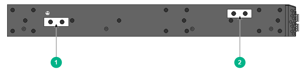
Figure 6 Left side panel
|
(1) Primary grounding point |
(2) Auxiliary grounding point |
S6861-30QF
Figure 7 Front panel
|
(1) SFP+ port LED |
(2) SFP+ port |
|
(3) QSFP+ port LED |
(4) QSFP+ port |
Figure 8 Rear panel

|
(1) System status LED (SYS) |
(2) LINK/ACT LED for the copper management Ethernet port |
|
(3) LINK/ACT LED for the fiber management Ethernet port |
(4) Fan tray 1 |
|
(5) Fan tray 2 |
(6) Fan tray 3 |
|
(7) Fan tray 4 |
(8) Power module 1 |
|
(9) Power module 2 |
(10) Fiber management Ethernet port |
|
(11) Copper management Ethernet port |
(12) Console port |
|
(13) Mini USB console port |
(14) USB port |
An S6861-30QF switch comes with power module slot PWR1 empty and power module slot PWR2 installed with a filler panel. In Figure 2, two PSR450-12A power modules are installed in the power module slots.
An S6861-30QF switch comes with the four fan tray slots empty. You must install four fan trays of the same model for the switch. In Figure 2, four LSPM1FANSA fan trays are installed in the fan tray slots.
Figure 9 Left side panel
|
(1) Primary grounding point |
(2) Auxiliary grounding point |
Removable components
|
|
CAUTION: · Select fan trays and power modules with airflow directions that meet the ventilation requirements at the installation site. As a best practice, make sure the power modules and fan trays have the same airflow direction. · Do not install fan trays of different models on the same switch. · Do not install power modules of different models on the same switch. |
Table 2 FRUs available for the S6861 switches
|
FRUs |
Part number in BOM |
S6861-54QF |
S6861-30QF |
S6861-54QT |
|
Power modules |
||||
|
PSR250-12A |
0231A6M0 |
Yes |
Yes |
No |
|
PSR250-12A1 |
0231A8FP |
Yes |
Yes |
No |
|
PSR450-12A |
0231A6N9 |
Yes |
Yes |
Yes |
|
PSR450-12A1 |
0231A6NC |
Yes |
Yes |
Yes |
|
PSR450-12AHD |
0231A6NA |
Yes |
Yes |
Yes |
|
PSR450-12D |
0231A6NB |
Yes |
Yes |
Yes |
|
Fan trays |
||||
|
LSPM1FANSA |
0231A2VT |
Yes |
Yes |
Yes |
|
LSPM1FANSB |
0231A2VU |
Yes |
Yes |
Yes |
Power modules
|
|
CAUTION: When the switch has power modules in redundancy, you can replace a power module without powering off the switch. Make sure the power module to be replaced is powered off before you replace it. |
|
|
IMPORTANT: As a best practice, use power modules of the same model in 1+1 redundancy for power supply. |
Table 3 Power module specifications
|
Power module |
Specifications |
Remarks |
|
PSR250-12A (with an airflow direction from the power module side to the port side) PSR250-12A1 (with an airflow direction from the port side to the power module side) |
· AC input: ¡ Rated input voltage: 100 to 240 VAC @ 50/60 Hz ¡ Max input voltage: 90 to 290 VAC @ 47 to 63 Hz ¡ Max output power: 250 W · DC input: ¡ Rated input voltage: 240 VDC ¡ Max input voltage: 180 to 320 VDC ¡ Max output power: 250 W |
For more information about the power modules, see H3C PSR250-12A & PSR250-12A1 Power Modules User Manual. |
|
PSR450-12A (with an airflow direction from the power module side to the port side) PSR450-12A1 (with an airflow direction from the port side to the power module side) |
· AC input: ¡ Rated input voltage: 100 to 240 VAC @ 50/60 Hz ¡ Max input voltage: 90 to 290 VAC @ 47 to 63 Hz ¡ Max output power: 450 W · DC input: ¡ Rated input voltage: 240 VDC ¡ Max input voltage: 180 to 320 VDC ¡ Max output power: 450 W |
For more information about the power modules, see H3C PSR450 Power Module Series User Manual. |
|
PSR450-12AHD (with an airflow direction from the port side to the power module side) |
· AC input ¡ Rated voltage: 100 to 240 VAC @ 50/60 Hz ¡ Max voltage: 90 to 290 VAC @ 47 to 63 Hz ¡ Max output power: 450 W · High-voltage DC input ¡ Rated voltage: 240 to 380 VDC ¡ Max voltage: 180 to 400 VDC ¡ Max output power: 450 W |
|
|
PSR450-12D (with an airflow direction from the port side to the power module side) |
· Rated input voltage: –48 to –60 VDC · Max input voltage: –36 to –72 VDC · Max output power: 450 W |
Fan trays
Table 4 Fan tray specifications
|
Item |
Specifications |
|
LSPM1FANSA |
|
|
Fans |
One 40 × 40 × 28 mm (1.57 × 1.57 × 1.10 in) fan |
|
Fan speed |
20000 R.P.M |
|
Max airflow |
20 CFM |
|
Airflow direction |
From the power module side to the port side |
|
Input voltage |
12 V |
|
Maximum power consumption |
9.8 W |
|
Documentation reference |
H3C LSPM1FANSA & LSPM1FANSB Fan Trays User Guide |
|
LSPM1FANSB |
|
|
Fans |
One 40 × 40 × 28 mm (1.57 × 1.57 × 1.10 in) fan |
|
Fan speed |
20000 R.P.M |
|
Max airflow |
20 CFM |
|
Airflow direction |
From the port side to the power module side |
|
Input voltage |
12 V |
|
Maximum power consumption |
9.8 W |
|
Documentation reference |
H3C LSPM1FANSA & LSPM1FANSB Fan Trays User Guide |
Ports and LEDs
Ports
Console port
The switch has two console ports: serial console port and Mini USB console port.
Table 5 Console port specifications
|
Item |
Console port |
Mini USB console port |
|
Connector type |
RJ-45 |
USB mini-Type B |
|
Compliant standard |
EIA/TIA-232 |
USB 2.0 |
|
Transmission baud rate |
9600 bps (default) to 115200 bps |
|
|
Services |
· Provides connection to an ASCII terminal. · Provides connection to the serial port of a local or remote (through a pair of modems) PC running terminal emulation program. |
· Provides connection to an ASCII terminal. · Provides connection to the USB port of a local PC running terminal emulation program. |
Management Ethernet port
The switch provides a copper and a fiber management Ethernet port.
You can connect a management Ethernet port to a PC or management station for loading and debugging software or remote management.
Table 6 Copper management Ethernet port specifications
|
Item |
Specification |
|
Connector type |
RJ-45 |
|
Connector quantity |
1 |
|
Port transmission rate |
10/100/1000 Mbps, half/full duplex |
|
Transmission medium and max transmission distance |
100 m (328.08 ft) over category-5 twisted pair cable |
|
Functions and services |
Switch software and Boot ROM upgrade, network management |
Table 7 Fiber management Ethernet port specifications
|
Item |
Specification |
|
Connector type |
LC |
|
Connector quantity |
1 |
|
Port transmission rate |
100/1000 Mbps, full duplex |
|
Transmission medium and max transmission distance |
|
|
Functions and services |
Software upgrade and network management |
Table 8 FE SFP transceiver modules
|
FE SFP transceiver module |
Central wavelength (nm) |
Connector |
Fiber type and diameter (µm) |
Max transmission distance |
|
SFP-FE-SX-MM1310-A |
1310 |
LC |
Multi-mode, 50/125 |
2 km (1.24 miles) |
|
Multi-mode, 62.5/125 |
||||
|
SFP-FE-LX-SM1310-A |
1310 |
LC |
Single-mode, 9/125 |
15 km (9.32 miles) |
|
SFP-FE-LH40-SM1310 |
1310 |
LC |
Single-mode, 9/125 |
40 km (24.86 miles) |
USB port
The switch has one OHC-compliant USB2.0 port that can upload and download data at a rate up to 480 Mbps. You can use this USB port to access the file system on the Flash of the switch, for example, to upload or download application and configuration files.
|
|
NOTE: USB devices from different manufacturers vary in compatibilities and drivers. H3C does not guarantee the correct operation of all USB devices on the switch. If a USB device fails to operate on the switch, replace it with one from another manufacturer. |
SFP+ port
The S6861-54QF and S6861-30QF switches provide SFP+ ports. The following transceiver modules and cables are available for the SFP+ ports:
· Gigabit SFP transceiver modules in Table 9.
|
|
IMPORTANT: Ports 29 to 36 on the front panel of the S6861-54QF switch do not support Gigabit SFP copper or fiber transceiver modules. |
· 10-Gigabit SFP+ transceiver modules in Table 10.
· 10-Gigabit SFP+ copper cables in Table 11.
· 10-Gigabit SFP+ fiber cables in Table 12.
Table 9 Gigabit SFP transceiver modules available for the SFP+ ports
|
Gigabit SFP transceiver module |
Central wavelength (nm) |
Connector |
Cable/Fiber type and diameter (µm) |
Modal bandwidth (MHz × km) |
Max transmission distance |
|
SFP-GE-T (GE SFP copper transceiver module) |
N/A |
RJ-45 |
Twisted pair cable |
N/A |
100 m (328.08 ft) |
|
SFP-GE-SX-MM850-A |
850 |
LC |
Multi-mode, 50/125 |
500 |
550 m (1804.46 ft) |
|
400 |
500 m (1640.42 ft) |
||||
|
Multi-mode, 62.5/125 |
200 |
275 m (902.23 ft) |
|||
|
160 |
200 m (656.17 ft) |
||||
|
SFP-GE-LX-SM1310-A |
1310 |
LC |
Single-mode, 9/125 |
N/A |
10 km (6.21 miles) |
|
Multi-mode, 50/125 |
500 or 400 |
550 m (1804.46 ft) |
|||
|
Multi-mode, 62.5/125 |
500 |
550 m (1804.46 ft) |
|||
|
SFP-GE-LH40-SM1310 |
1310 |
LC |
Single-mode, 9/125 |
N/A |
40 km (24.86 miles) |
|
SFP-GE-LH40-SM1550 |
1550 |
LC |
Single-mode, 9/125 |
N/A |
40 km (24.86 miles) |
|
SFP-GE-LH80-SM1550 |
1550 |
LC |
Single-mode, 9/125 |
N/A |
80 km (49.71 miles) |
|
|
IMPORTANT: Installed with an SFP-GE-T transceiver module, an SFP+ port can operate only at 1 Gbps. |
Table 10 10-Gigabit SFP+ transceiver modules available for the SFP+ ports
|
10-Gigabit SFP+ transceiver module |
Central wavelength (nm) |
Connector |
Fiber type and diameter (µm) |
Modal bandwidth (MHz × km) |
Max transmission distance |
|
SFP-XG-SX-MM850-A |
850 |
LC |
Multi-mode, 50/125 |
2000 |
300 m (984.25 ft) |
|
500 |
82 m (269.03 ft) |
||||
|
400 |
66 m (216.54 ft) |
||||
|
Multi-mode, 62.5/125 |
200 |
33 m (108.27 ft) |
|||
|
160 |
26 m (85.30 ft) |
||||
|
SFP-XG-LX-SM1310 |
1310 |
LC |
Single-mode, 9/125 |
N/A |
10 km (6.21 miles) |
Table 11 SFP+ copper cables available for the SFP+ ports
|
SFP+ copper cable |
Max transmission distance |
|
LSWM1STK |
0.65 m (2.13 ft) |
|
LSWM2STK |
1.2 m (3.94 ft) |
|
LSWM3STK |
3 m (9.84 ft) |
|
LSTM1STK |
5 m (16.40 ft) |
Table 12 SFP+ fiber cables available for the SFP+ ports
|
SFP+ fiber cable |
Max transmission distance |
Data rate |
|
SFP-XG-D-AOC-7M |
7 m (22.97 ft) |
10.31 Gbps |
|
SFP-XG-D-AOC-10M |
10 m (32.81 ft) |
|
|
SFP-XG-D-AOC-20M |
20 m (65.62 ft) |
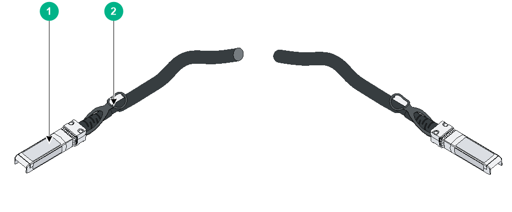
Figure 10 SFP+ copper cable
|
(1) Connector |
(2) Pull latch |
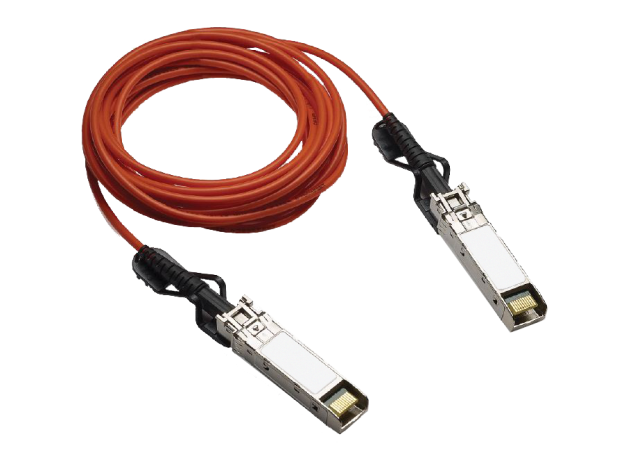
Figure 11 SFP+ fiber cable
|
|
NOTE: · As a best practice, use H3C transceiver modules and cables for the switch. The H3C transceiver modules and cables are subject to change over time. For the most recent list of H3C transceiver modules and cables, contact H3C Support or marketing staff. · For more information about H3C transceiver modules and cables, see H3C Transceiver Modules User Guide. |
QSFP+ port
The switch provides fixed QSFP+ ports. You can install QSFP+ transceiver modules in Table 13, QSFP+ cables in Table 14, and QSFP+ to SFP+ cables in Table 15 in the QSFP+ ports as needed.
Table 13 QSFP+ transceiver modules available for the QSFP+ ports
|
Central wavelength (nm) |
Connector |
Fiber type and diameter (µm) |
Modal bandwidth (MHz × km) |
Max transmission distance |
|
|
QSFP-40G-SR4-MM850 |
850 |
MPO |
Multi-mode, 50/125 |
2000 |
100 m (328.08 ft) |
|
4700 |
150 m (492.12 ft) |
||||
|
QSFP-40G-CSR4-MM850 |
850 |
MPO |
Multi-mode, 50/125 |
2000 |
300 m (984.25 ft) |
|
4700 |
400 m (1312.33 ft) |
||||
|
QSFP-40G-BIDI-SR-MM850 |
850 |
LC |
Multi-mode, 50/125 |
2000 |
100 m (328.08 ft) |
|
4700 |
150 m (492.12 ft) |
||||
|
QSFP-40G-LR4-WDM1300 |
Four lanes: · 1271 · 1291 · 1311 · 1331 |
LC |
Single-mode, 9/125 |
N/A |
10 km (6.21 miles) |
|
QSFP-40G-LR4L-WDM1300 |
Four lanes: · 1271 · 1291 · 1311 · 1331 |
LC |
Single-mode, 9/125 |
N/A |
2 km (1.24 miles) |
|
QSFP-40G-LR4-PSM1310 |
1310 |
MPO |
Single-mode, 9/125 |
N/A |
10 km (6.21 miles) |
Table 14 QSFP+ cables available for the QSFP+ ports
|
QSFP+ cable |
Max transmission distance |
|
LSWM1QSTK0 |
1 m (3.28 ft) |
|
LSWM1QSTK1 |
3 m (9.84 ft) |
|
LSWM1QSTK2 |
5 m (16.40 ft) |
Table 15 QSFP+ to SFP+ cables available for the QSFP+ ports
|
QSFP+ to SFP+ cable |
Max transmission distance |
|
LSWM1QSTK3 |
1 m (3.28 ft) |
|
LSWM1QSTK4 |
3 m (9.84 ft) |
|
LSWM1QSTK5 |
5 m (16.40 ft) |
Table 16 QSFP+ fiber cables available for the QSFP+ ports
|
QSFP+ fiber cable |
Max transmission distance |
Data rate |
|
QSFP-40G-D-AOC-7M |
7 m (22.97 ft) |
40 Gbps |
|
QSFP-40G-D-AOC-10M |
10 m (32.81 ft) |
|
|
QSFP-40G-D-AOC-20M |
20 m (65.62 ft) |
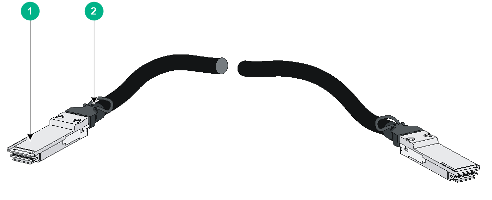
Figure 12 QSFP+ cable
|
(1) Connector |
(2) Pull latch |
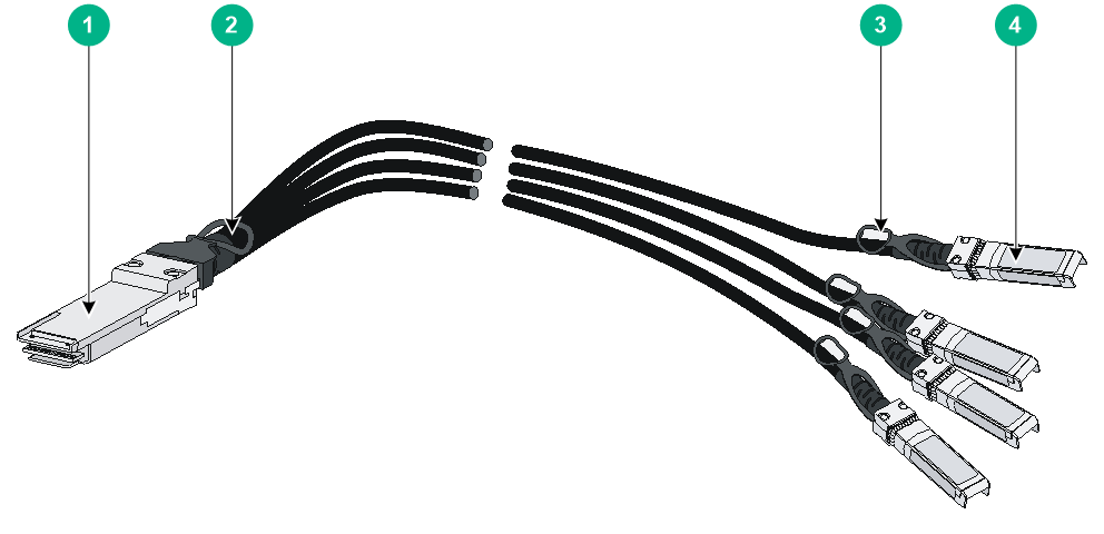
Figure 13 QSFP+ to SFP+ cable
|
(1) QSFP+ module |
(2) QSFP+ side pull latch |
|
(3) SFP+ side pull latch |
(4) SFP+ module |
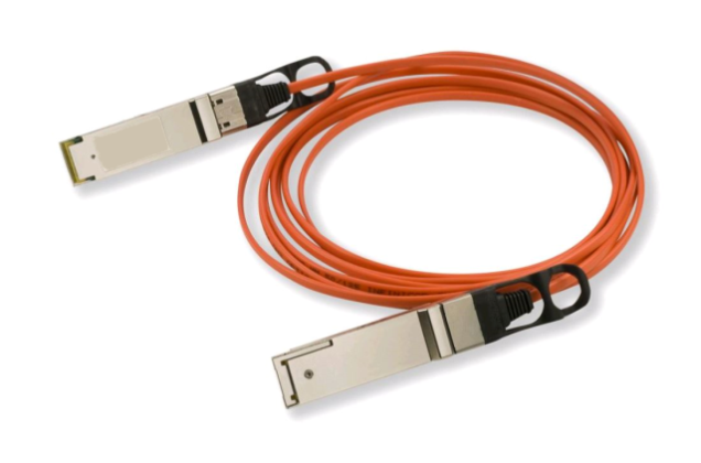
Figure 14 QSFP+ fiber cable
|
|
IMPORTANT: You can use a QSFP-40G-SR4-MM850 or QSFP-40G-CSR4-MM850 transceiver module to connect a QSFP+ port to four SFP+ ports. The QSFP+ transceiver module and SFP+ transceiver modules to be connected must be the same in specifications, including central wavelength and fiber type. |
|
|
NOTE: · As a best practice, use H3C transceiver modules and cables for the switch. The H3C transceiver modules and cables are subject to change over time. For the most recent list of H3C transceiver modules and cables, contact H3C Support or marketing staff. · For more information about H3C transceiver modules and cables, see H3C Transceiver Modules User Guide. |
1/10GBASE-T autosensing Ethernet port
The S6861-54QT switch provides 1/10GBASE-T autosensing Ethernet ports.
Ports 29 to 36 on the front panel of the S6861-54QT switch cannot operate at 1000 Mbps. You can set the speed of the ports to 10000 Mbps or configure the ports to negotiate a speed with their peers. The negotiated speed can only be 10000 Mbps.
Table 17 1/10GBASE-T autosensing Ethernet port specifications
|
Item |
Specification |
|
Connector type |
RJ-45 |
|
Port transmission rate |
1/10 Gbps, full duplex, MDI/MDI-X autosensing |
|
Transmission medium and max transmission distance |
· 55 m (180.45 ft) over category-6 unshielded twisted pair cable · 100 m (328.08 ft) over category-6 shielded twisted pair cable · 100 m (328.08 ft) over category-6A or above twisted pair cable |
|
Compatible standards |
· IEEE 802.3ab · IEEE 802.3an |
To avoid interference between cables, layer cables as follows:
· Use category-6A or above cables and connectors.
· Do not bundle cables in their first 20 m (65.62 ft).
· Separate power cords and twisted pair cables at and around the distribution frame.
· For ports adjacent to one another on the device, the peer ports on the distribution frame are preferably not adjacent, for example:
¡ If the device connects to one distribution frame, connect port 1 on the device to port 1 on the distribution frame, port 2 on the device to port 3 on the distribution frame, and port 3 on the device to port 5 on the distribution frame.
¡ If the device connects to two distribution frames, connect port 1 on the device to port 1 on distribution frame 1, port 2 on the device to port 1 on distribution frame 2, and port 3 on the device to port 2 on distribution frame 1.
LEDs
System status LED
The system status LED shows the operating status of the switch.
Table 18 System status LED description
|
LED mark |
Status |
Description |
|
SYS |
Steady green |
The switch is operating correctly. |
|
Flashing green |
The switch is performing power-on self test (POST). |
|
|
Steady red |
The system has failed POST, or a fault has occurred. |
|
|
Flashing red |
Some ports have failed POST. |
|
|
Off |
The switch is powered off or has failed to start up. |
SFP+ port LED
Each SFP+ port has a status LED to show its operating status and activities.
Table 19 SFP+ port LED description
|
LED status |
Description |
|
Steady green |
A transceiver module or cable has been correctly installed. The port has a link and is operating at 10 Gbps. |
|
Flashing green |
The port is sending or receiving data at 10 Gbps. |
|
Steady yellow |
A transceiver module or cable has been correctly installed. The port has a link and is operating at 1 Gbps. |
|
Flashing yellow (3 Hz) |
The port is sending or receiving data at 1 Gbps. |
|
Off |
No transceiver module or cable has been installed or no link is present on the port. |
QSFP+ port LED
Each QSFP+ port has a status LED to show its operating status and activities.
Table 20 QSFP+ port LED description
|
LED status |
Description |
|
Steady green |
A transceiver module or cable has been correctly installed. The port has a link and is operating at 40 Gbps. |
|
Flashing green |
The port is sending or receiving data at 40 Gbps. |
|
Steady yellow |
A transceiver module or cable has been correctly installed. The port has a link and is operating at 10 Gbps. |
|
Flashing yellow (3 Hz) |
The port is sending or receiving data at 10 Gbps. |
|
Off |
No transceiver module or cable has been installed or no link is present on the port. |
Management Ethernet port LEDs
The switch provides a LINK/ACT LED for each management Ethernet port. For LED description for the copper management Ethernet port, see Table 21. For LED description for the fiber management Ethernet port, see Table 22.
Table 21 Copper management Ethernet port LED description
|
LED mark |
Status |
Description |
|
LINK/ACT |
Steady green |
The port is operating at 10/100/1000 Mbps and a link is present. |
|
Flashing green |
The port is receiving or sending data. |
|
|
Off |
No link is present. |
Table 22 Fiber management Ethernet port LED description
|
LED mark |
Status |
Description |
|
LINK/ACT |
Off |
No link is present. |
|
Steady green |
The port is operating at 100/1000 Mbps and a link is present. |
|
|
Flashing green |
The port is receiving or sending data. |
1/10GBASE-T autosensing Ethernet port LEDs
Table 23 1/10GBASE-T autosensing Ethernet port LED description
|
Status |
Description |
|
Steady green |
The port has a link and is operating at 10 Gbps. |
|
Flashing green |
The port is sending or receiving data at 10 Gbps. |
|
Steady yellow |
The port has a link and is operating at 1 Gbps. |
|
Flashing yellow |
The port is sending or receiving data at 1 Gbps. |
|
Off |
No link is present on the port. |
Fan tray alarm LEDs
The LSPM1FANSA and LSPM1FANSB fan trays provide an Alarm LED.
Table 24 Fan tray alarm LED description
|
Status |
Description |
|
On |
The fan tray is faulty. |
|
Off |
The fan tray is operating correctly. |
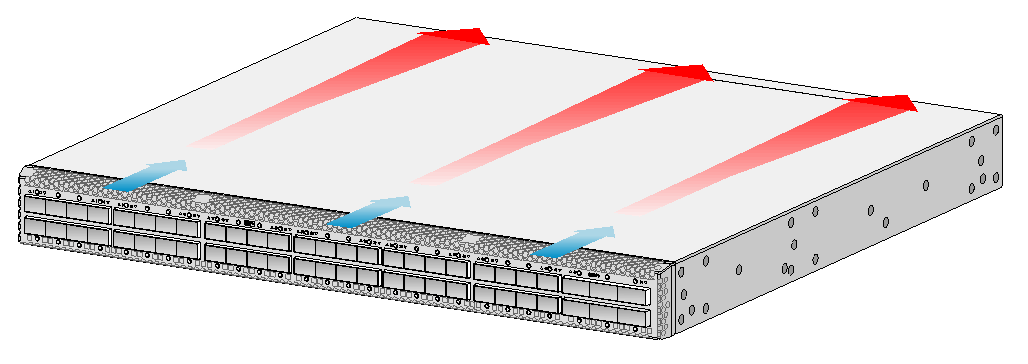
Cooling system
|
|
CAUTION: To guarantee heat dissipation, you must install fan trays of the same model for the switch. |
To dissipate heat timely and ensure system stability, the switch uses the front-rear air aisle cooling system. Consider the site ventilation design when you plan the installation site for the switch.
Table 25 Cooling system for the switch
|
Available fan trays |
Airflow direction |
|
LSPM1FANSA |
From the power module side to the port side |
|
LSPM1FANSB |
From the port side to the power module side |
Figure 15 Airflow from the power module side to the port side through the S6861-54QF chassis (with LSPM1FANSA fan trays)
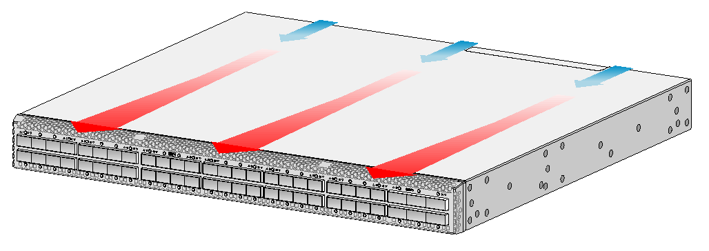
Figure 16 Airflow from the port side to the power module side through the S6861-54QF chassis (with LSPM1FANSB fan trays)