- Table of Contents
- Related Documents
-
| Title | Size | Download |
|---|---|---|
| 01-Installation Guide | 12.16 MB |
Examining the installation site
Installing the switch in a 19-inch rack
Rack-mounting procedures at a glance
Attaching the mounting brackets, chassis rails, and grounding cable to the chassis
Attaching the slide rails to the rack
Mounting the switch in the rack
Grounding the switch by using a grounding strip
Installing and removing a fan tray
Installing and removing a power module
Connecting the power cord for a PSR250-12A/PSR250-12A1/PSR450-12A/PSR450-12A1 power module
Connecting the power cord for a PSR450-12AHD power module
Connecting the DC power cord for a PSR450-12D power module
Accessing the switch for the first time
Setting up the configuration environment
Planning IRF fabric size and the installation site
Identifying the master switch and planning IRF member IDs
Planning IRF topology and connections
Identifying physical IRF ports on the member switches
Configuring basic IRF settings
Connecting the physical IRF ports
Accessing the IRF fabric to verify the configuration
Maintenance and troubleshooting
No display on the configuration terminal
Garbled display on the configuration terminal
Preparing for installation
H3C S6861 switch series includes the following models:
· S6861-54QF.
· S6861-54QT.
· S6861-30QF.
Safety recommendations
To avoid any equipment damage or bodily injury caused by incorrect use, read the following safety recommendations before installation. Note that the recommendations do not cover every possible hazardous condition.
· Before cleaning the switch, remove all power cords from the switch. Do not clean the switch with wet cloth or liquid.
· Do not place the switch near water or in a damp environment. Prevent water or moisture from entering the switch chassis.
· Do not place the switch on an unstable case or desk. The switch might be severely damaged in case of a fall.
· Ensure good ventilation of the equipment room and keep the air inlet and outlet vents of the switch free of obstruction.
· Make sure the operating voltage is in the required range.
· To avoid electrical shocks, do not open the chassis while the switch is operating or when the switch is just powered off.
· When replacing FRUs, including power modules and fan trays, wear an ESD wrist strap to avoid damaging the units.
Examining the installation site
The switch must be used indoors.
Mount your switch in a rack and verify the following items:
· Adequate clearance is reserved at the air inlet and outlet vents for ventilation.
· The rack has a good ventilation system.
· Identify the hot aisle and cold aisle at the installation site, and make sure ambient air flows into the switch from the cold aisle and exhausts to the hot aisle.
· Identify the airflow designs of neighboring devices, and prevent hot air flowing out of the bottom device from entering the top device.
· The rack is sturdy enough to support the switch and its accessories.
· The rack is reliably grounded.
To ensure correct operation and long service life of your switch, install it in an environment that meets the requirements described in the following subsections.
Temperature/humidity
Maintain appropriate temperature and humidity in the equipment room.
· Lasting high relative humidity can cause poor insulation, electricity leakage, mechanical property change of materials, and metal corrosion.
· Lasting low relative humidity can cause washer contraction and ESD and cause problems including loose screws and circuit failure.
· High temperature can accelerate the aging of insulation materials and significantly lower the reliability and lifespan of the switch.
For the temperature and humidity requirements of different switch models, see hardware information and specifications for the switch.
Cleanliness
Dust buildup on the chassis might result in electrostatic adsorption, which causes poor contact of metal components and contact points. In the worst case, electrostatic adsorption can cause communication failure.
Table 1 Dust concentration limits in the equipment room
|
Substance |
Particle diameter |
Concentration limit |
|
Dust particles |
≥ 0.5 µm |
≤ 3.5 × 10⁶ particles/m3 |
|
Dust particles |
≥ 5 µm |
≤ 3 × 10⁴ particles/m3 |
|
Dust (suspension) |
≤ 75 µm |
≤ 0.2 mg/m3 |
|
Dust (sedimentation) |
75 µm to 150 µm |
≤ 1.5 mg/(m2h) |
Corrosive gases can accelerate corrosion and aging of components. Make sure the corrosive gases in the equipment room do not exceed the concentration limits as shown in Table 2.
Table 2 Corrosive gas concentration limits in the equipment room
|
Gas |
Average concentration (mg/m3) |
Maximum concentration (mg/m3) |
|
SO2 |
0.3 |
1.0 |
|
H2S |
0.1 |
0.5 |
|
Cl2 |
0.1 |
0.3 |
|
HCI |
0.1 |
0.5 |
|
HF |
0.01 |
0.03 |
|
NH3 |
1.0 |
3.0 |
|
O3 |
0.05 |
0.1 |
|
NOX |
0.5 |
1.0 |
EMI
All electromagnetic interference (EMI) sources, from outside or inside of the switch and application system, adversely affect the switch in the following ways:
· A conduction pattern of capacitance coupling.
· Inductance coupling.
· Electromagnetic wave radiation.
· Common impedance (including the grounding system) coupling.
To prevent EMI, use the following guidelines:
· If AC power is used, use a single-phase three-wire power receptacle with protection earth (PE) to filter interference from the power grid.
· Keep the switch far away from radio transmitting stations, radar stations, and high-frequency devices.
· Use electromagnetic shielding, for example, shielded interface cables, when necessary.
· To prevent signal ports from getting damaged by overvoltage or overcurrent caused by lightning strikes, route interface cables only indoors.
Laser safety
|
|
WARNING! · The switch is a Class 1 laser device. · Disconnected optical fibers or transceiver modules might emit invisible laser light. Do not stare into beams or view directly with optical instruments when the switch is operating. |
Installation tools
No installation tools are provided with the switch. Prepare the following tools yourself:
· Flathead screwdriver
· Phillips screwdriver.
· ESD wrist strap.
· Marker.
Installation accessories
Before installation, make sure you have all the required installation accessories. If any accessory is damaged or missing, use the part number provided in this table to purchase a new one.
Table 3 Installation accessories
|
Part number in BOM |
Description |
Quantity |
|
0223A15H |
Mounting brackets
|
1 kit (provided) |
|
2150A050 |
1U rack mounting rail kit (long slide rails)
|
1 kit (provided) |
|
2150A05D |
1U rack mounting rail kit
|
Optional |
|
2150A0CP |
1U rack mounting rail kit (super-short slide rails)
|
Optional |
|
N/A |
M6 screw and cage nut
|
User supplied |
|
0404A0KM |
Grounding cable
|
1 (provided) |
|
26010553 |
Grounding screw
|
2 (provided) |
|
2114A09C |
Power module filler panel
|
1 (provided) |
|
N/A |
Releasable cable tie
|
User supplied |
|
04042967 |
Serial console cable
|
1 (provided) |
|
14990101 |
SFP port dust plug
|
Same number as the SFP+ and SPF ports |
|
1499A01G |
QSFP port dust plug
|
Same number as the QSFP+ ports |

Installing the switch
|
|
CAUTION: Keep the tamper-proof seal on a mounting screw on the chassis cover intact, and if you want to open the chassis, contact H3C for permission. Otherwise, H3C shall not be liable for any consequence caused thereby. |
Figure 1 Hardware installation flow

Installing the switch in a 19-inch rack
Installation accessories
Table 4 Installation accessories
|
Switch model |
Mounting brackets |
Rack mounting rail kit |
|
S6861-54QF S6861-30QF |
1U high, one pair (provided). See Figure 2. |
· 1U high, including one pair of chassis rails and one pair of long slide rails (provided). See Figure 5. · 1U high, including one pair of chassis rails and one pair of super-short slide rails (optional). See Figure 3. |
|
S6861-54QT |
1U high, one pair (provided). See Figure 3. |
· 1U high, including one pair of chassis rails and one pair of long slide rails (provided). See Figure 5. · 1U high, including one pair of chassis rails and one pair of slide rails (optional). See Figure 4. |
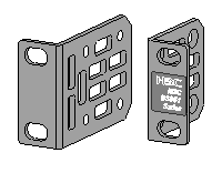
Figure 3 1U chassis rail and super-short slide rail
|
(1) Chassis rail |
(2) Super-short slide rail |
Figure 4 1U chassis rail and slide rail
|
(1) Chassis rail |
(2) Slide rail |
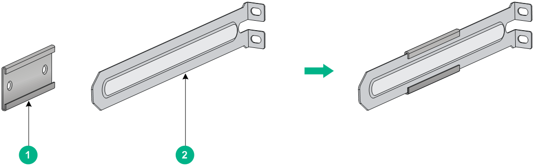
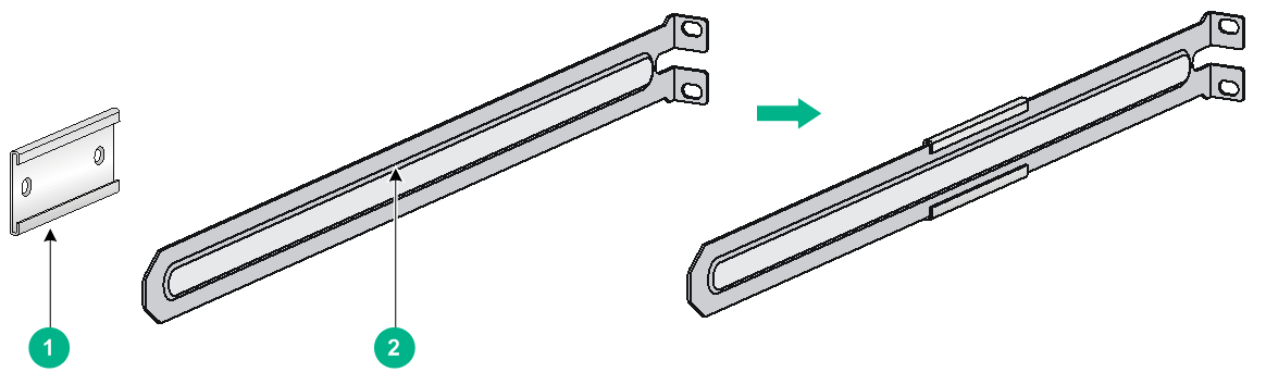
Figure 5 1U chassis rail and long slide rail
|
(2) Long slide rail |
Rack-mounting procedures at a glance
Figure 6 Rack-mounting procedure

|
|
NOTE: If a rack shelf is available, you can put the switch on the rack shelf, slide the switch to an appropriate location, and attach the switch to the rack with the mounting brackets. |
Follow these guidelines when you install the switch in a 19-inch rack:
· The distance between the front and rear posts of the rack must meet the requirements described in Table 5.
· To secure the switch to the rack, you must install not only mounting brackets, but also chassis rails and slide rails.
Table 5 Distance requirements between the front and rear rack posts
|
Switch model |
Installation method |
Minimum distance between the front and rear rack posts |
Maximum distance between the front and rear rack posts |
|
S6861-54QF S6861-30QF |
Using mounting brackets, chassis rails, and long slide rails |
621 mm (24.45 in) |
793 mm (31.22 in) |
|
Using mounting brackets, chassis rails, and super-short slide rails (narrow-spacing installation) |
330 mm (12.99 in) |
505 mm (19.88 in) |
|
|
Using mounting brackets, chassis rails, and super-short slide rails (wide-spacing installation) |
438 mm (17.24 in) |
632 mm (24.88 in) |
|
|
S6861-54QT |
Using mounting brackets, chassis rails, and long slide rails |
621 mm (24.45 in) |
854 mm (33.62 in) |
|
Using mounting brackets, chassis rails, and slide rails |
401 mm (15.79 in) |
634 mm (24.96 in) |
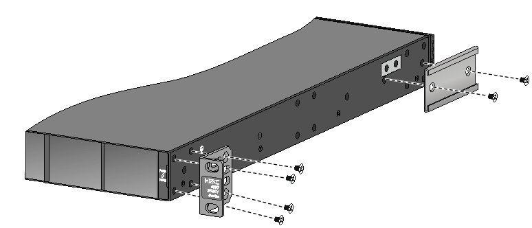
Attaching the mounting brackets, chassis rails, and grounding cable to the chassis
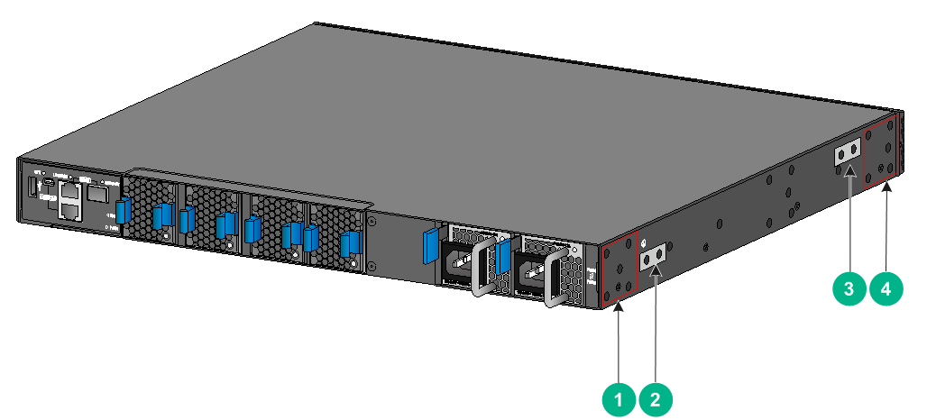
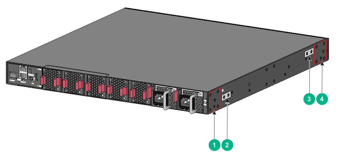
The switch has two mounting bracket installation positions on its two sides: one near the network port side and one near the power module side.
The switch provides a primary grounding point (with a grounding sign) and an auxiliary grounding point.
Figure 7 Mounting bracket installation positions and grounding positions on the S6861-54QF and S6861-30QF switches
|
(1) Mounting bracket installation position near the power module side |
|
|
(2) Primary grounding point |
(3) Auxiliary grounding point |
|
(4) Mounting bracket installation position near the port side |
|
Figure 8 Mounting bracket installation positions and grounding positions on the S6861-54QT switch
|
(1) Mounting bracket installation position near the power module side |
|
|
(2) Primary grounding point |
(3) Auxiliary grounding point |
|
(4) Mounting bracket installation position near the port side |
|
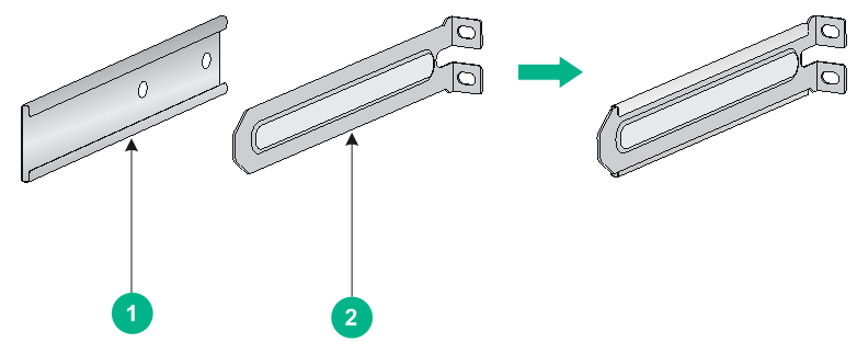
Attaching the mounting brackets and chassis rails to the chassis
|
|
CAUTION: M4 screws are used to attach the mounting brackets and chassis rails to the chassis. As a best practice, use a torque of 12 kgf-cm (1.18 Nm) to fasten M4 screws. |
The mounting bracket and chassis rail installation methods are the same for the S6861-54QF and S6861-30QF switches.
To attach the mounting brackets and chassis rails to the chassis:
1. Align the mounting brackets with the screw holes in the chassis. Use M4 screws (provided) to attach the mounting brackets to the chassis.
¡ To install the mounting brackets at the port side, see Figure 9, Figure 10, Figure 11, and Figure 12.
¡ To install the mounting brackets at the power module side, see Figure 13, Figure 14, Figure 15, and Figure 16.
2. Align the chassis rails with the rail mounting holes in the chassis:
¡ If the mounting brackets are in the port-side mounting position, align the chassis rails with the screw holes at the rear of the side panels (see Figure 9, Figure 10, Figure 11, and Figure 12).
¡ If the mounting brackets are in the power module-side mounting position, align the chassis rails with the screw holes at the front of the side panels (see Figure 13, Figure 14, Figure 15, and Figure 16).
3. Use M4 screws (provided) to attach the chassis rails to the chassis.
Secure the mounting brackets and chassis rails to both sides of the chassis in the same way.
To use super-short slide rails for the switch, you can install the chassis rails through narrow-spacing or wide-spacing installation, depending on the distance between the front and rear rack posts, as shown in Figure 10, Figure 11, Figure 14, and Figure 15.
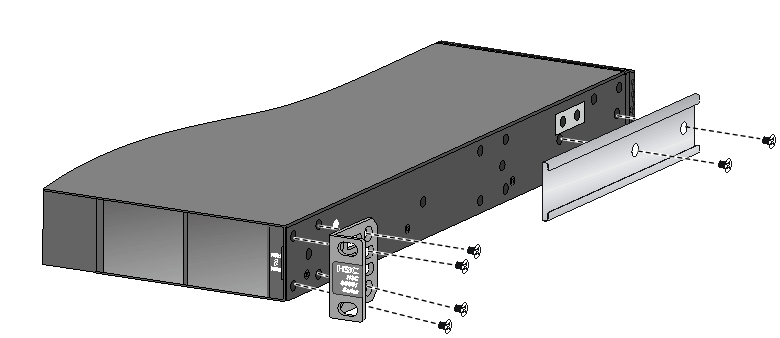
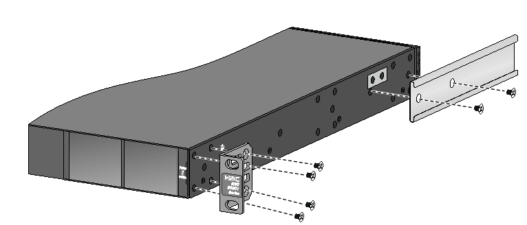
Figure 9 Attaching the mounting brackets and chassis rails to an S6861-54QF switch (mounting brackets installed near the port side)
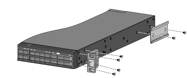
Figure 10 Attaching the mounting brackets and chassis rails (narrow-spacing installation) to an S6861-54QF switch (mounting brackets installed near the port side)
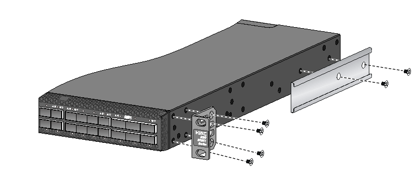
Figure 11 Attaching the mounting brackets and chassis rails (wide-spacing installation) to an S6861-54QF switch (mounting brackets installed near the port side)
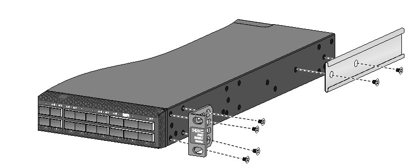
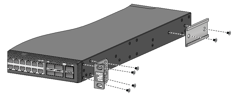
Figure 13 Attaching the mounting brackets and chassis rails to an S6861-54QF switch (mounting brackets installed near the power module side)
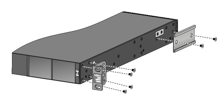
Figure 14 Attaching the mounting brackets and chassis rails (narrow-spacing installation) to an S6861-54QF (mounting brackets installed near the power module side)
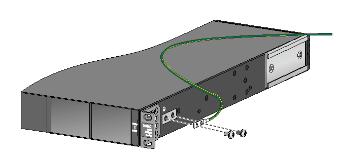
Connecting the grounding cable to the chassis
|
|
CAUTION: Select a grounding point as required. The primary grounding point and auxiliary grounding point are located on the left side panel. If you use one of these grounding points, you must connect the grounding cable to the grounding point before you mount the switch in the rack. |
|
|
CAUTION: Grounding screws are used to attach the grounding cable to the switch. As a best practice, use a torque of 20 kgf-cm (1.96 Nm) to fasten the grounding screws. |
This section uses the primary grounding point on an S6861-54QF switch as an example.
To connect the grounding cable to a grounding point:
1. Choose a grounding point. As a best practice, use the grounding point close to the mounting brackets.
2. Unpack the grounding cable and grounding screws.
You can use the cable and screws shipped with the switch for connecting to the primary grounding point or auxiliary grounding point.
3. Align the two-hole grounding lug at one end of the cable with the grounding holes of the grounding point, insert the grounding screws into the holes, and tighten the screws with a screwdriver, as shown in Figure 17.
Figure 17 Attaching the grounding cable to the primary grounding point on an S6861-54QF switch
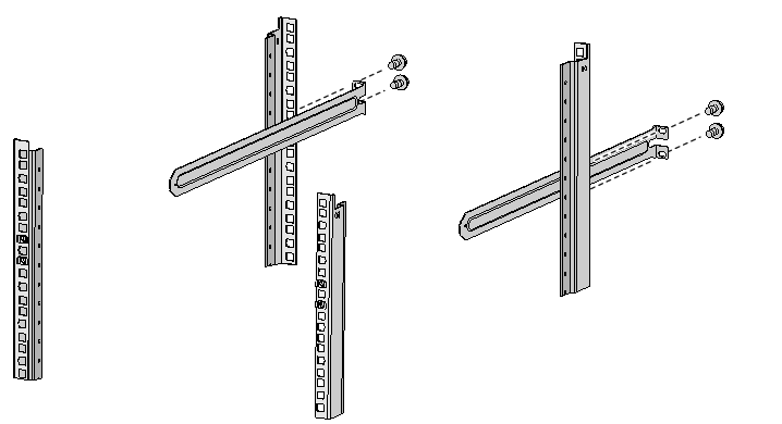
Attaching the slide rails to the rack
|
|
IMPORTANT: M6 screws and cage nuts are used to attach the slide rails to the rack. Prepare M6 screws and cage nuts yourself. As a best practice, use a torque of 30 kgf-cm (2.94 Nm) to fasten the M6 screws. |
The procedures are the same for attaching slide rails to the rack. This section uses the 1U long slide rails as an example.
To attach the slide rails to the rack:
1. Identify the rack attachment position for the slide rails.
2. Install cage nuts (user-supplied) in the mounting holes in the rack posts.
3. Align the screw holes in one slide rail with the cage nuts in the rack post on one side, and use screws matching the cage nuts to attach the slide rail to the rack, as shown in Figure 18.
4. Repeat the preceding steps to attach the other slide rail to the rack post on the other side.
Keep the two slide rails at the same height so the slide rails can attach into the chassis rails.
Figure 18 Installing the 1U long slide rails
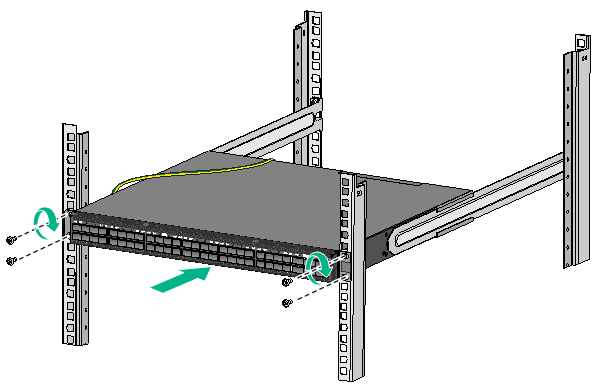
Mounting the switch in the rack
|
|
IMPORTANT: M6 screws are used to attach the mounting brackets to the rack. Prepare M6 screws yourself. As a best practice, use a torque of 30 kgf-cm (2.94 Nm) to fasten the M6 screws. |
The rack-mounting procedure is similar for the switches. The following procedure mounts an S6861-54QF switch in a rack.
This task requires two people.
To mount the switch in the rack:
1. Wear an ESD wrist strap and make sure it makes good skin contact and is reliably grounded.
2. Verify that the mounting brackets and chassis rails have been securely attached to the switch chassis.
3. Verify that the slide rails have been correctly attached to the rear rack posts.
4. Install cage nuts (user-supplied) to the front rack posts and make sure they are at the same level as the slide rails.
5. One person performs the following operations:
a. Supporting the bottom of the switch, aligns the chassis rails with the slide rails on the rack posts.
b. Pushes the switch slowly to slide the chassis rails along the slide rails until the mounting brackets are flush with the rack posts.
6. The other person uses M6 screws to attach the mounting brackets to the rack.
If the slide rails or long slide rails are used, make sure the front ends of the slide rails or long slide rails reach out of the chassis rails. If the super-short slide rails are used, make sure the super-short slide rails slide a minimum length of 90 mm (3.54 in) into the chassis rails.
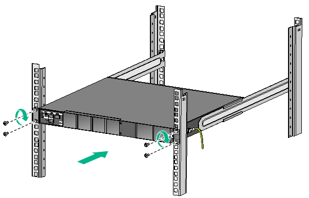
Figure 20 Mounting an S6861-54QF switch in the rack (mounting brackets installed near the port side)
Grounding the switch by using a grounding strip
|
|
CAUTION: · Correctly connecting the grounding cable is crucial to lightning protection and EMI protection. For information about lightning protection for the switch, see H3C Lightning Protection Guide. · Do not connect the grounding cable to a fire main or lightning rod. · To guarantee the grounding effect and avoid switch damage, use the grounding cable provided with the switch to connect the switch to a grounding strip in the equipment room. |
The power input end of the switch has a noise filter, whose central ground is directly connected to the chassis to form the chassis ground (commonly known as PGND). You must securely connect this chassis ground to the earth so the faradism and leakage electricity can be safely released to the earth to minimize EMI susceptibility of the switch.
To ground the switch by using a grounding strip:
1. Attach the two-hole grounding lug at one end of the grounding cable to a grounding point on the switch chassis. For more information, see "Connecting the grounding cable to the chassis."
2. Remove the hex nut of a grounding post on the grounding strip.
3. Attach the ring terminal at the other end of the grounding cable to the grounding post on the grounding strip, and secure the ring terminal to the grounding post with the hex nut.
Figure 21 Connecting the grounding cable to a grounding strip
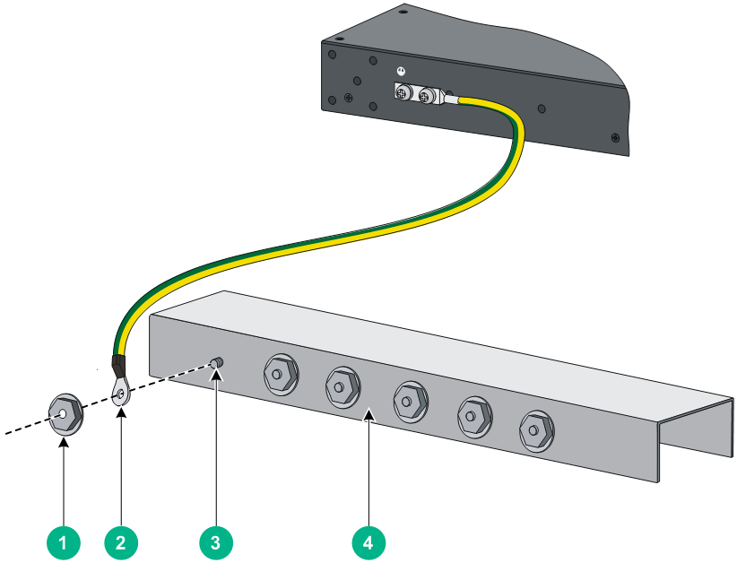
|
(1) Hex nut |
(2) Ring terminal |
|
(3) Grounding post |
(4) Grounding strip |
Installing and removing a fan tray
|
|
CAUTION: · Do not power on the switch unless all fan tray slots are installed with a fan tray. · Install fan trays of the same model on the switch. · Make sure all slots have a module or filler panel installed when the switch is operating. · If more than one fan tray fail during the switch operation, replace the faulty fan trays one by one and finish replacing a fan tray within three minutes. |
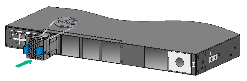
Installing a fan tray
|
|
CAUTION: To prevent damage to the fan tray or the connectors on the backplane, insert the fan tray gently. If you encounter a hard resistance while inserting the fan tray, pull out the fan tray and insert it again. |
Select appropriate fan trays as needed. For the optional fan trays and their specifications, see hardware information and specifications for the switch.
To installing an LSPM1FANSA or LSPM1FANSB fan tray:
1. Wear an ESD wrist strap and make sure it makes good skin contact and is reliably grounded.
2. Unpack the fan tray and verify that the fan tray model is correct.
3. Orient the fan tray with the "TOP" mark on the top. Grasp the handle of the fan tray with one hand and support the fan tray bottom with the other, and slide the fan tray along the guide rails into the slot until the fan tray is fully seated in the slot and has a firm contact with the backplane.
Figure 22 Installing an LSPM1FANSA fan tray
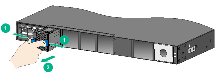
Removing a fan tray
|
|
WARNING! · Ensure electricity safety and never touch the rotating fans when you hot-swap a fan tray. · To prevent an unbalanced fan from causing loud noise, do not touch the fans, even if they are not rotating. · Do not touch any bare wires and terminals on a fan tray. · Do not place a fan tray in a moist location or let liquid flow into it. · Contact H3C Support if the circuits or components on a fan tray are faulty. Do not remove any fan tray components. |
To remove an LSPM1FANSA or LSPM1FANSB fan tray:
1. Wear an ESD wrist strap and make sure it makes good skin contact and is reliably grounded.
2. Grasp the fan tray handle and pull out the fan tray slowly along the guide rails.
3. Place the removed fan tray in an antistatic bag.
Figure 23 Removing an LSPM1FANSA fan tray
Installing and removing a power module
|
|
WARNING! · In power redundancy mode, you can replace a power module without powering off the switch but must strictly follow the installation and procedures in Figure 24 and Figure 25 to avoid any bodily injury or damage to the switch. · Provide a separate circuit breaker for each power module. |
|
|
CAUTION: Do not install power modules with different models on the same switch. |
The switch comes with power module slot PWR1 empty and power module slot PWR2 installed with a filler panel.
For more information about available power modules and their specifications, see hardware information and specifications for the switch.
Figure 24 Installation procedure
![]()
![]()
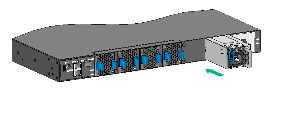
Installing a power module
|
CAUTION: · Follow the forward inertia of the power module when inserting it into the chassis, and make sure the power module has firm contact with the connectors on the backplane. · To prevent damage to the connectors inside the switch chassis, insert the power module gently. If you encounter a hard resistance while inserting the power module, pull out the power module and insert it again. · As a best practice for heat dissipation, make sure each empty power module slot is installed with a filler panel. |
The installation procedure is the same for power modules of different models. The following procedure installs a PSR250-12A power module on an S6861-54QF switch.
To install a power module:
1. Wear an ESD wrist strap and make sure it makes good skin contact and is reliably grounded.
2. Remove the filler panel from the target power module slot, if any, as shown in Figure 26.
Figure 26 Removing the filler panel from a power module slot
3. Unpack the power module and verify that the power module model is correct.
4. Correctly orient the power module with the power module slot (see Figure 27), grasp the handle of the power module with one hand and support its bottom with the other, and slide the power module slowly along the guide rails into the slot.
The slot is foolproof. If you cannot insert the power module into the slot, re-orient the power module rather than use excessive force to push it in.
Figure 27 Installing a power module
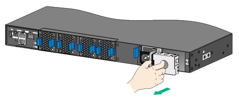
Removing a power module
|
|
CAUTION: When the switch has two power modules in 1+1 redundancy mode, removing one power module does not affect the operation of the switch. When the switch has only one power module installed, removing the power module powers off the switch. |
Removing a PSR250-12A/PSR250-12A1 or PSR450-12A/PSR450-12A1 power module
The removal procedure is the same for the PSR250-12A/PSR250-12A1 and PSR450-12A/PSR450-12A1 power modules. The following procedure removes a PSR250-12A power module from an S6861-54QF switch.
To remove a PSR250-12A power module:
1. Wear an ESD wrist strap and make sure it makes good skin contact and is reliably grounded.
2. Remove the power cord.
3. Hold the handle on the power module with one hand, pivot the latch on the power module to the right with your thumb, and pull the power module part way out of the slot, as shown in Figure 28.
4. Supporting the power module bottom with one hand, slowly pull the power module out with the other hand.
5. Put away the removed power module in an antistatic bag for future use.
Figure 28 Removing a PSR250-12A power module
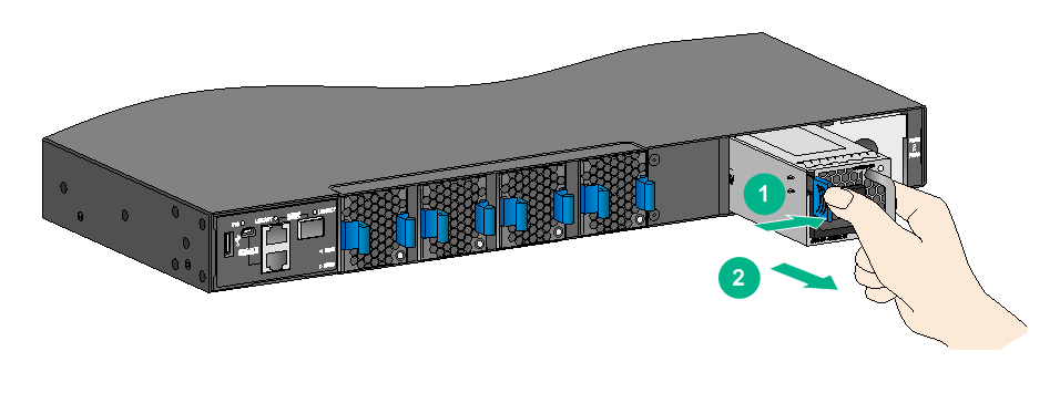
|
(1) Pivot the latch to the right with your thumb |
(2) Pull the power module out |
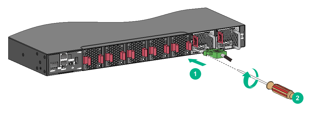
Removing a PSR450-12AHD power module
The following procedure removes a PSR450-12AHD power module from an S6861-54QT switch.
To remove a PSR450-12AHD power module:
1. Wear an ESD wrist strap and make sure it makes good skin contact and is reliably grounded.
2. Open the cable clamp (see Figure 29), and then remove the power cord connector from the power module (see Figure 30).
Figure 29 Opening the cable clamp
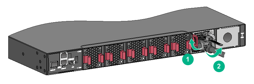
Figure 30 Removing the power cord from the power module
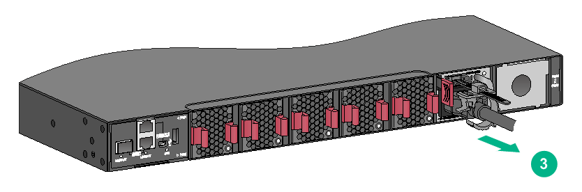
3. Hold the handle of the power module with one hand, press the latch on the power module to the right with your thumb, and pull the power module part way out of the slot. Supporting the power module bottom with one hand, slowly pull the power module out of the slot along the guide rails with the other.
Removing a PSR450-12D DC power module
The following procedure removes a PSR450-12D power module from an S6861-54QT switch.
To remove a PSR450-12D power module:
1. Wear an ESD wrist strap and make sure it makes good skin contact and is reliably grounded.
2. Use a flat-head screwdriver to loosen the screws on the power cord connector, and then pull the connector out to remove the power cord. See Figure 31.
3. Hold the handle on the power module with one hand, pivot the latch on the power module to the right with your thumb, and pull the power module part way out of the slot, as shown in Figure 28.
4. Supporting the power module bottom with one hand, slowly pull the power module out with the other hand.
5. Put the removed power module in an antistatic bag for future use.
Figure 31 Removing a PSR450-12D power module
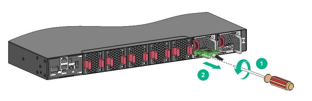
|
(1) Use a flathead screwdriver to loosen the screws on the power cord connector |
|
(2) Pull the power cord out |
Connecting the power cord
|
|
WARNING! Provide a circuit breaker for each power input. When you connect a power cord, make sure the circuit breaker is switched off. |
Connecting the power cord for a PSR250-12A/PSR250-12A1/PSR450-12A/PSR450-12A1 power module
1. Insert the female connector of the power cord supplied with the power module into the power receptacle on the power module.
2. Use a cable tie to secure the power cord to the handle of the power module, as shown in Figure 32.
3. Connect the other end of the power cord to an AC or DC power source.
Figure 32 Connecting the power cord (PSR250-12A power module)
|
(1) Cable tie |
|
(2) Tighten the cable tie to secure the power cord to the handle of the power module |
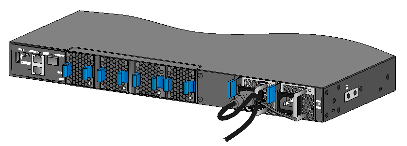
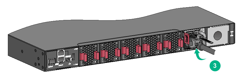
Connecting the power cord for a PSR450-12AHD power module
1. Slide the cable clamp onto the tie mount on the power module, as shown in Figure 33.
2. Connect the female connector of the power cord to the power receptacle on the power module, as shown in Figure 34
3. Close the cable clamp and slide it forward until it is flush against the edge of the female connector, as shown in Figure 35.
4. Connect the other end of the power cord to an AC or DC power source.
Figure 33 Connecting the power cord for a PSR450-12AHD power module (1)

Figure 34 Connecting the power cord for a PSR450-12AHD power module (2)
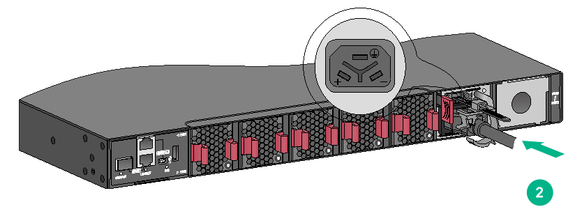
Figure 35 Connecting the power cord for a PSR450-12AHD power module (3)
Connecting the DC power cord for a PSR450-12D power module
1. Correctly orient the DC power cord plug and insert the plug into the power receptacle on the power module.
If you orient the DC power cord plug upside down, you cannot insert the plug into the power receptacle.
2. Use a flat-head screwdriver to fasten the screws on the power cord connector, as shown in Figure 36.
3. Connect the other end of the power cord to the DC power source.
Figure 36 Connecting the DC power cord for a PSR450-12D power module
If the provided DC power cord cannot meet your connection requirements, use the following table to prepare a suitable copper cable as the DC power cord.
Table 6 Requirements for a suitable DC power cord
|
Power module model |
Power cord connector |
Minimum cross sectional area of the conductor |
Cross sectional area of the provided power cord |
Maximum cross sectional area of the conductor |
|
PSR450-12D |
Use the connector of the provided power cord |
2.1 mm2 or 14 AWG |
3.3 mm2 or 12 AWG |
3.3 mm2 or 12 AWG |
Verifying the installation
After you complete the installation, verify the following items:
· There is enough space for heat dissipation around the switch, and the rack is stable.
· The grounding cable is securely connected.
· The correct power source is used.
· The power cords are correctly connected.
· If part of the network cable for a port is routed outdoors, verify that a network port lightning protector is used for the port.
· If a power line is routed from outdoors, verify that a surge protected power strip is used for the switch.
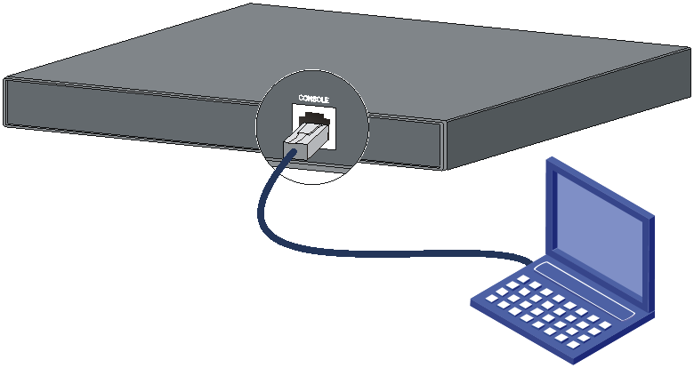
Accessing the switch for the first time
Setting up the configuration environment
You can use the serial console port or the mini USB console port to connect the switch to a configuration terminal. These two configuration methods cannot be used simultaneously.
As a best practice, use the serial console port to connect the switch to a configuration terminal. The switch is provided with a serial console cable.
To connect the switch to a configuration terminal through the mini USB console port, prepare a mini USB console cable yourself.
This example uses the serial console port to connect the switch to a configuration terminal (PC).
Figure 37 Connecting the serial console port to a terminal
Connecting the console cable
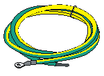
Serial console cable
A serial console cable is an 8-core cable, with a crimped RJ-45 connector at one end for connecting to the serial console port of the switch, and a DB-9 female connector at the other end for connecting to the serial port on the console terminal.
Figure 38 Serial console cable
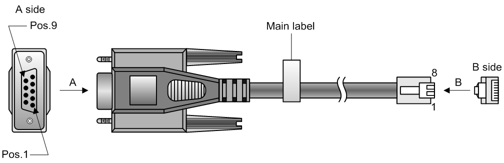
Table 7 Serial console cable pinout
|
RJ-45 |
Signal |
DB-9 |
Signal |
|
1 |
RTS |
8 |
CTS |
|
2 |
DTR |
6 |
DSR |
|
3 |
TXD |
2 |
RXD |
|
4 |
SG |
5 |
SG |
|
5 |
SG |
5 |
SG |
|
6 |
RXD |
3 |
TXD |
|
7 |
DSR |
4 |
DTR |
|
8 |
CTS |
7 |
RTS |
USB mini console cable
A USB mini console cable has a USB mini-Type B connector at one end to connect to the Mini USB console port of the switch, and a standard USB Type A connector at the other end to connect to the USB port on the configuration terminal.
Connection procedure
To connect a terminal (for example, a PC) to the switch by using the serial console cable:
1. Plug the DB-9 female connector of the serial console cable to the serial port of the PC.
2. Connect the RJ-45 connector to the serial console port of the switch.
|
|
NOTE: · Identify the mark on the console port and make sure you are connecting to the correct port. · The serial ports on PCs do not support hot swapping. If the switch has been powered on, connect the serial console cable to the PC before connecting to the switch, and when you disconnect the cable, first disconnect from the switch. |
To connect to the configuration terminal through the USB mini console cable:
1. Connect the standard USB Type A connector to the USB port of the configuration terminal.
2. Connect the USB mini Type B connector to the Mini USB console port of the switch.
3. Click the following link, or copy it to the address bar on the browser to log in to download page of the USB console driver, and download the driver.
4. Select a driver program according to the operating system you use:
¡ XR21V1410_XR21B1411_Windows_Ver1840_x86_Installer.EXE—32-bit operating system.
¡ XR21V1410_XR21B1411_Windows_Ver1840_x64_Installer.EXE—64-bit operating system.
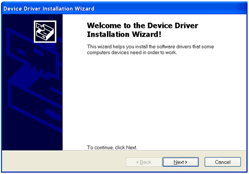
5. Click Next on the installation wizard.
Figure 39 Device Driver Installation Wizard
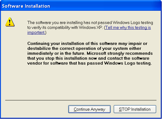
6. Click Continue Anyway if the following dialog box appears.
Figure 40 Software Installation
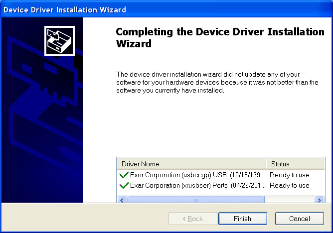
7. Click Finish.
Figure 41 Completing the device driver installation wizard
Setting terminal parameters
To configure and manage the switch through the console port, you must run a terminal emulator program, HyperTerminal or PuTTY, on your configuration terminal. You can use the emulator program to connect a network device, a Telnet site, or an SSH site. For more information about the terminal emulator programs, see the user guides for these programs
The following are the required terminal settings:
· Bits per second—9600.
· Data bits—8.
· Stop bits—1.
· Parity—None.
· Flow control—None.
Powering on the switch
Before powering on the switch, verify that the following conditions are met:
· The power cord is correctly connected.
· The input power voltage meets the requirement of the switch.
· The console cable is correctly connected.
· The configuration terminal (a PC, for example) has started, and its serial port settings are consistent with the console port settings on the switch.
Power on the switch. During the startup process, you can access Boot ROM menus to perform tasks such as software upgrade and file management. The Boot ROM interface and menu options differ with software versions. For more information about Boot ROM menu options, see the software-matching release notes for the device.
After the startup completes, you can access the CLI to configure the switch.
For more information about the configuration commands and CLI, see H3C S6861 Switch Series Configuration Guides and H3C S6861 Switch Series Command References.
Setting up an IRF fabric
You can use H3C IRF technology to connect and virtualize S6861 switches into a large virtual switch called an "IRF fabric" for flattened network topology, and high availability, scalability, and manageability.
The switch can set up an IRF fabric only with switches of the same switch series.
The 10-GE and 40-GE ports on the switch can be used for IRF connections.
IRF fabric setup flowchart
Figure 42 IRF fabric setup flowchart
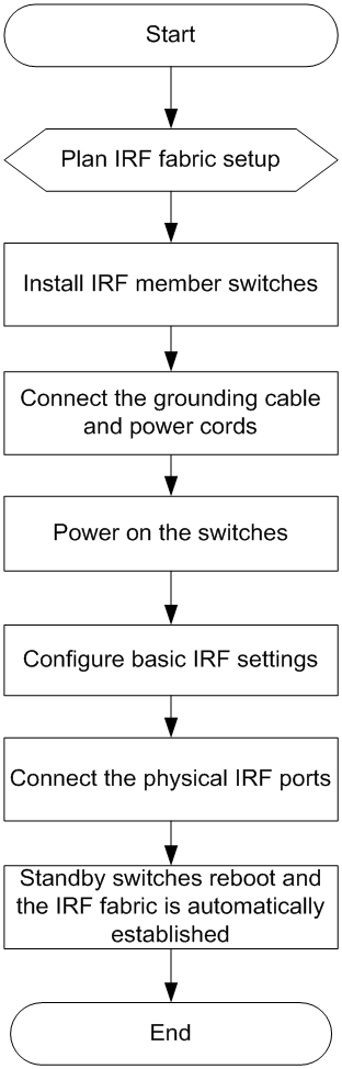
To set up an IRF fabric:
|
Step |
Description |
|
1. Plan IRF fabric setup. |
Plan the installation site and IRF fabric setup parameters: · Planning IRF fabric size and the installation site · Identifying the master switch and planning IRF member IDs · Planning IRF topology and connections · Identifying physical IRF ports on the member switches · Planning the cabling scheme |
|
2. Install IRF member switches. |
See "Installing the switch in a 19-inch rack." |
|
3. Connect ground wires and power cords. |
See "Grounding the switch by using a grounding strip" and "Connecting the power cord." |
|
4. Power on the switches. |
N/A |
|
5. Configure basic IRF settings. |
See H3C S6861 Switch Series IRF Configuration Guide or H3C S6861 Switch Series Virtual Technologies Configuration Guide, depending on the software version. |
|
6. Connect the physical IRF ports. |
Connect the physical IRF ports on switches. Use SFP+/QSFP+ transceiver modules and fibers for a long-distance connection. Use twisted pair cables, SFP+ cables, or QSFP+ cables for a short-distance connection. All switches except the master switch automatically reboot, and the IRF fabric is established. |
Planning IRF fabric setup
This section describes issues that an IRF fabric setup plan must cover.
Planning IRF fabric size and the installation site
Choose switch models and identify the number of required IRF member switches, depending on the user density and upstream bandwidth requirements. The switching capacity of an IRF fabric equals the total switching capacities of all member switches.
Plan the installation site depending on your network solution as follows:
· Place all IRF member switches in one rack for centralized high-density access.
· Distribute the IRF member switches in different racks to implement the top-of-rack (ToR) access solution for a data center.
As your business grows, you can plug H3C S6861 switches into the IRF fabric to increase the switching capacity without any topology change or replacement.
Identifying the master switch and planning IRF member IDs
Determine which switch you want to use as the master for managing all member switches in the IRF fabric. An IRF fabric has only one master switch. You configure and manage all member switches in the IRF fabric at the command line interface of the master switch.
|
|
NOTE: IRF member switches will automatically elect a master. You can affect the election result by assigning a high member priority to the intended master switch. For more information about master election, see H3C S6861 Switch Series IRF Configuration Guide or H3C S6861 Switch Series Virtual Technologies Configuration Guide, depending on the software version. |
Prepare an IRF member ID assignment scheme. An IRF fabric uses member IDs to uniquely identify and manage its members, and you must assign each IRF member switch a unique member ID.
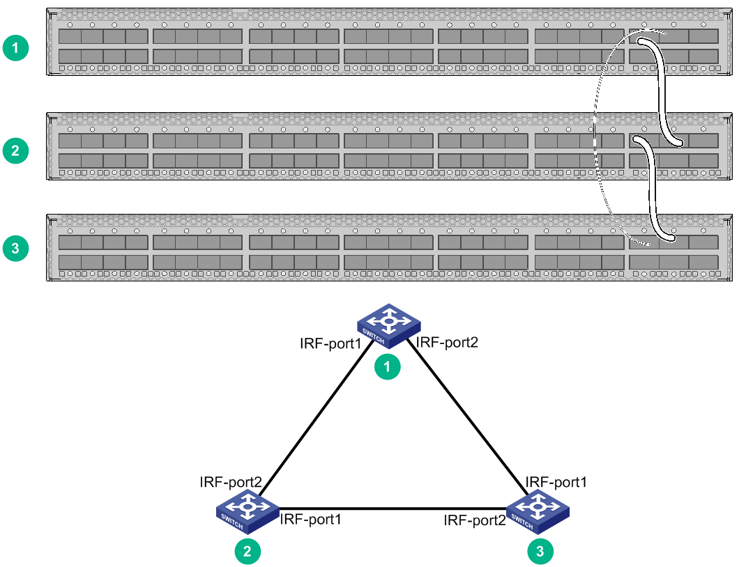
Planning IRF topology and connections
You can create an IRF fabric in daisy chain topology, or more reliably, ring topology. In ring topology, the failure of one IRF link does not cause the IRF fabric to split as in daisy chain topology. Rather, the IRF fabric changes to a daisy chain topology without interrupting network services.
You connect the IRF member switches through IRF ports, the logical interfaces for the connections between IRF member switches. Each IRF member switch has two IRF ports: IRF-port 1 and IRF-port 2. To use an IRF port, you must bind at least one physical port to it.
When connecting two neighboring IRF member switches, you must connect the physical ports of IRF-port 1 on one switch to the physical ports of IRF-port 2 on the other switch.
The IRF port connections in the two figures are for illustration only, and more connection methods are available.
Figure 43 IRF fabric in daisy chain topology
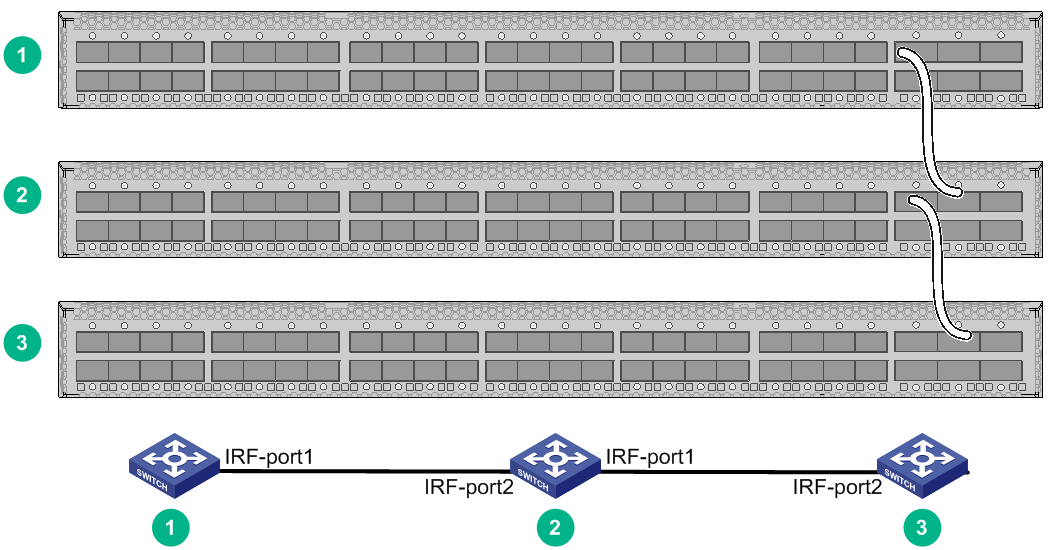
Figure 44 IRF fabric in ring topology
Depending on the switch model, you can connect the physical ports between the switches as follows for IRF connections:
· Connect 10GBASE-T Ethernet ports or SFP+ ports to provide a 10-GE IRF physical connection.
· Connect QSFP+ ports to provide a 40-GE IRF physical connection.
· Connect a QSFP+ port and four SFP+ ports by using a 40G QSFP+ to 4 × 10G SFP+ cable.
You can bind several ports to an IRF port for increased bandwidth and availability.
Identifying physical IRF ports on the member switches
Identify the 10GBASE-T Ethernet ports, SFP+ ports, and QSFP+ ports to be used for IRF connections on the member switches according to your topology and connection scheme.
All the 10GBASE-T Ethernet ports, SFP+ ports, and QSFP+ ports on the switch can be used for IRF connections.
Planning the cabling scheme
You can use twisted pair cables, SFP+/QSFP+ cables, or SFP+/QSFP+ transceiver modules and optical fibers to connect the switches for IRF connections. For a long-distance connection, use SFP+/QSFP+ transceiver modules and optical fibers. For a short-distance connection, use twisted pair cables, SFP+ cables, or QSFP+ cables. For more information about available transceiver modules and cables, see hardware information and specifications for the switch.
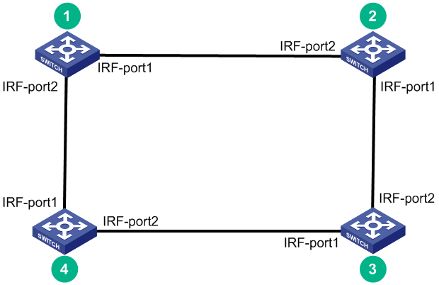
The following subsections describe several H3C recommended IRF connection schemes, and all these schemes use a ring topology.
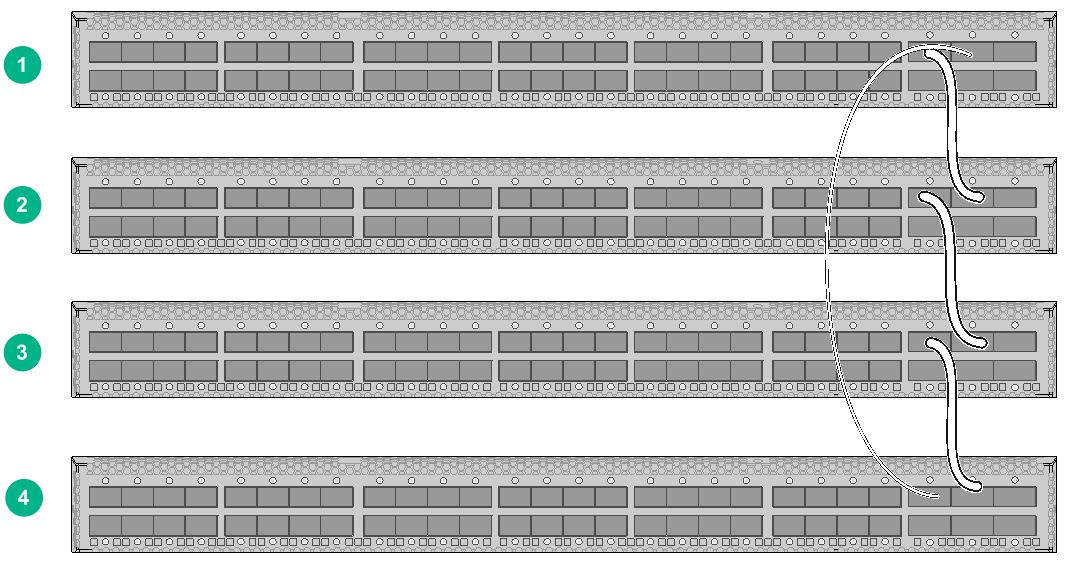
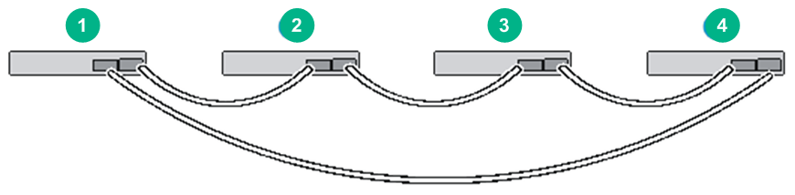
Connecting the IRF member switches in one rack
Figure 45 shows an example for connecting four IRF member switches in a rack by using QSFP+ cables and QSFP+ transceiver modules and optical fibers. The switches in the ring topology (see Figure 46) are in the same order as connected in the rack.
Figure 45 Connecting the switches in one rack
Connecting the IRF member switches in a ToR solution
You can install IRF member switches in different racks side by side to deploy a top of rack (ToR) solution.
Figure 47 shows an example for connecting four top of rack IRF member switches by using QSFP+ cables and QSFP+ transceiver modules and optical fibers. The topology is the same as Figure 46.
Configuring basic IRF settings
After you install the IRF member switches, power on the switches, and log in to each IRF member switch (see H3C S6861 Switch Series Fundamentals Configuration Guide) to configure their member IDs, member priorities, and IRF port bindings.
Follow these guidelines when you configure the switches:
· Assign the master switch higher member priority than any other switch.
· Bind physical ports to IRF port 1 on one switch and to IRF port 2 on the other switch. You perform IRF port binding before or after connecting IRF physical ports depending on the software release.
· Execute the display irf configuration command to verify the basic IRF settings.
For more information about configuring basic IRF settings, see H3C S6861 Switch Series IRF Configuration Guide or H3C S6861 Switch Series Virtual Technologies Configuration Guide, depending on the software version.
Connecting the physical IRF ports
|
|
CAUTION: Wear an ESD wrist strap when you connect cables or transceiver modules and optical fibers. For more information, see the installation guide for the transceiver modules. |
Use cables or transceiver modules and optical fibers to connect the IRF member switches as planned.
Accessing the IRF fabric to verify the configuration
To verify the basic functionality of the IRF fabric after you finish configuring basic IRF settings and connecting IRF ports:
1. Log in to the IRF fabric through the console port of any member switch.
2. Create a Layer 3 interface, assign it an IP address, and make sure the IRF fabric and the remote network management station can reach each other.
3. Use Telnet or SNMP to access the IRF fabric from the network management station. (See H3C S6861 Switch Series Fundamentals Configuration Guide.)
4. Verify that you can manage all member switches as if they were one node.
5. Display the running status of the IRF fabric by using the commands in Table 8.
Table 8 Displaying and maintaining IRF configuration and running status
|
Task |
Command |
|
Display information about the IRF fabric. |
display irf |
|
Display all members' IRF configurations. |
display irf configuration |
|
Display IRF fabric topology information. |
display irf topology |
|
|
NOTE: To avoid IP address collision and network problems, configure at least one multi-active detection (MAD) mechanism to detect the presence of multiple identical IRF fabrics and handle collisions. For more information about MAD detection, see H3C S6861 Switch Series IRF Configuration Guide or H3C S6861 Switch Series Virtual Technologies Configuration Guide, depending on the software version. |
Maintenance and troubleshooting
Power module failure
Symptom
The status LED on a power module is not steady green (active state) or flashing green (standby state).
You can use the status LED on a power module to identify a power module failure. For more information about the status LED on a power module, see H3C PSR250-12A & PSR250-12A1 Power Modules User Manual or H3C PSR450 Power Module Series User Manual.
Solution
To resolve the issue:
1. Verify that the power cord is correctly connected.
2. Verify that the power source is as required by the power module.
3. Verify that the operating temperature of the switch is in an acceptable range and good ventilation is provided for the power module.
4. If the issue persists, contact the H3C Support.
To replace a power module, see "Installing and removing a power module."
Fan tray failure
|
|
CAUTION: If more than one fan tray fails during the switch operation, do not remove the failed fan trays simultaneously. Replace the fan trays one by one and finish replacing each fan tray within 3 minutes. |
Symptom
The status LED on a fan tray is on and the system outputs fan tray alarm messages.
Solution
See "Installing and removing a fan tray" to replace the failed fan tray.
Configuration terminal issues
If the configuration environment setup is correct, the configuration terminal displays booting information when the switch is powered on. If the setup is incorrect, the configuration terminal displays nothing or garbled text.
No display on the configuration terminal
Symptom
The configuration terminal has no display when the switch is powered on.
Solution
To resolve the issue:
1. Verify that the power system is operating correctly.
2. Verify that the console cable has been connected correctly and no fault occurs on the console cable.
3. Verify that the following settings are configured for the terminal:
¡ Baud rate—9600.
¡ Data bits—8.
¡ Stop bits—1.
¡ Parity—None.
¡ Flow control—None.
4. If the issue persists, contact H3C Support.
Garbled display on the configuration terminal
Symptom
The configuration terminal displays garbled text.
Solution
To resolve the issue:
1. Verify that the following settings are configured for the terminal:
¡ Baud rate—9600.
¡ Data bits—8.
¡ Stop bits—1.
¡ Parity—None.
¡ Flow control—None.
2. If the issue persists, contact H3C Support.
