- Table of Contents
-
- 08-Layer 3—IP Routing Configuration Guide
- 00-Preface
- 01-Basic IP routing configuration
- 02-Static routing configuration
- 03-RIP configuration
- 04-OSPF configuration
- 05-IS-IS configuration
- 06-EIGRP configuration
- 07-BGP configuration
- 08-Policy-based routing configuration
- 09-IPv6 static routing configuration
- 10-RIPng configuration
- 11-OSPFv3 configuration
- 12-IPv6 policy-based routing configuration
- 13-Routing policy configuration
- 14-MTR configuration
- 15-RIR configuration
- Related Documents
-
| Title | Size | Download |
|---|---|---|
| 09-IPv6 static routing configuration | 235.55 KB |
Configuring IPv6 static routing
Restrictions: Hardware compatibility with IPv6 static routing
Configuring an IPv6 static route
Configuring an IPv6 static route with the gateway address as the next hop
Configuring an IPv6 floating static route
Configuring BFD for IPv6 static routes
About BFD for IPv6 static routes
Restrictions and guidelines for BFD
Configuring BFD control packet mode
Configuring BFD echo packet mode
Configuring IPv6 static route FRR
Restrictions and guidelines for IPv6 static route FRR
Configuring IPv6 static route FRR to automatically select a backup next hop
Enabling BFD echo packet mode for IPv6 static route FRR
Display and maintenance commands for IPv6 static routing
IPv6 static routing configuration examples
Example: Configuring basic IPv6 static route
Example: Configuring BFD for IPv6 static routes (direct next hop)
Example: Configuring BFD for IPv6 static routes (indirect next hop)
Example: Configuring IPv6 static route FRR
Configuring an IPv6 default route
Configuring IPv6 static routing
About IPv6 static routing
Static routes are manually configured and cannot adapt to network topology changes. If a fault or a topological change occurs in the network, the network administrator must modify the static routes manually. IPv6 static routing works well in a simple IPv6 network.
Restrictions: Hardware compatibility with IPv6 static routing
|
Hardware |
IPv6 static routing compatibility |
|
MSR610 |
No |
|
MSR810, MSR810-W, MSR810-W-DB, MSR810-LM, MSR810-W-LM, MSR810-10-PoE, MSR810-LM-HK, MSR810-W-LM-HK, MSR810-LM-CNDE-SJK, MSR810-CNDE-SJK, MSR810-EI, MSR810-LM-EA, MSR810-LM-EI |
Yes |
|
MSR810-LMS, MSR810-LUS |
Yes |
|
MSR810-SI, MSR810-LM-SI |
Yes |
|
MSR810-LMS-EA, MSR810-LME |
Yes |
|
MSR1004S-5G, MSR1004S-5G-CN |
Yes |
|
MSR1104S-W, MSR1104S-W-CAT6, MSR1104S-5G-CN, MSR1104S-W-5G-CN |
Yes |
|
MSR2600-6-X1, MSR2600-15-X1, MSR2600-15-X1-T |
Yes |
|
MSR2600-10-X1 |
Yes |
|
MSR 2630 |
Yes |
|
MSR3600-28, MSR3600-51 |
Yes |
|
MSR3600-28-SI, MSR3600-51-SI |
Yes |
|
MSR3600-28-X1, MSR3600-28-X1-DP, MSR3600-51-X1, MSR3600-51-X1-DP |
Yes |
|
MSR3600-28-G-DP, MSR3600-51-G-DP |
Yes |
|
MSR3610-I-DP, MSR3610-IE-DP, MSR3610-IE-ES, MSR3610-IE-EAD, MSR-EAD-AK770, MSR3610-I-IG, MSR3610-IE-IG |
Yes |
|
MSR3610-X1, MSR3610-X1-DP, MSR3610-X1-DC, MSR3610-X1-DP-DC, MSR3620-X1, MSR3640-X1 |
Yes |
|
MSR3610, MSR3620, MSR3620-DP, MSR3640, MSR3660 |
Yes |
|
MSR3610-G, MSR3620-G |
Yes |
|
MSR3640-G |
Yes |
|
MSR3640-X1-HI |
Yes |
|
Hardware |
IPv6 static routing compatibility |
|
MSR810-W-WiNet, MSR810-LM-WiNet |
Yes |
|
MSR830-4LM-WiNet |
Yes |
|
MSR830-5BEI-WiNet, MSR830-6EI-WiNet, MSR830-10BEI-WiNet |
Yes |
|
MSR830-6BHI-WiNet, MSR830-10BHI-WiNet |
Yes |
|
MSR2600-6-WiNet |
Yes |
|
MSR2600-10-X1-WiNet |
Yes |
|
MSR2630-WiNet |
Yes |
|
MSR3600-28-WiNet |
Yes |
|
MSR3610-X1-WiNet |
Yes |
|
MSR3610-WiNet, MSR3620-10-WiNet, MSR3620-DP-WiNet, MSR3620-WiNet, MSR3660-WiNet |
Yes |
|
Hardware |
IPv6 static routing compatibility |
|
MSR860-6EI-XS |
Yes |
|
MSR860-6HI-XS |
Yes |
|
MSR2630-XS |
Yes |
|
MSR3600-28-XS |
Yes |
|
MSR3610-XS |
Yes |
|
MSR3620-XS |
Yes |
|
MSR3610-I-XS |
Yes |
|
MSR3610-IE-XS |
Yes |
|
MSR3620-X1-XS |
Yes |
|
MSR3640-XS |
Yes |
|
MSR3660-XS |
Yes |
|
Hardware |
IPv6 static routing compatibility |
|
MSR810-LM-GL |
Yes |
|
MSR810-W-LM-GL |
Yes |
|
MSR830-6EI-GL |
Yes |
|
MSR830-10EI-GL |
Yes |
|
MSR830-6HI-GL |
Yes |
|
MSR830-10HI-GL |
Yes |
|
MSR1004S-5G-GL |
Yes |
|
MSR2600-6-X1-GL |
Yes |
|
MSR3600-28-SI-GL |
Yes |
Configuring an IPv6 static route
1. Enter system view.
system-view
2. Configure an IPv6 static route.
Public network:
ipv6 route-static ipv6-address prefix-length { interface-type interface-number [ next-hop-address ] | next-hop-address | vpn-instance d-vpn-instance-name nexthop-address } [ permanent | track track-entry-number ] [ preference preference ] [ tag tag-value ] [ description text ]
ipv6 route-static ipv6-address prefix-length srv6-policy { color color-value end-point ipv6 ipv6-address | name policy-name } [ sid sid ] [ preference preference ] [ tag tag-value ] [ description text ]
By default, no IPv6 static route is configured.
VPN:
ipv6 route-static vpn-instance s-vpn-instance-name ipv6-address prefix-length { interface-type interface-number [ next-hop-address ] | vpn-instance d-vpn-instance-name next-hop-address } [ permanent | track track-entry-number ] [ preference preference ] [ tag tag-value ] [ description text ]
ipv6 route-static vpn-instance s-vpn-instance-name ipv6-address prefix-length nexthop-address [ public ] [ permanent ] [ preference preference ] [ tag tag-value ] [ description text ]
ipv6 route-static vpn-instance s-vpn-instance-name ipv6-address prefix-length srv6-policy { color color-value end-point ipv6 ipv6-address | name policy-name } [ sid sid ] [ preference preference ] [ tag tag-value ] [ description text ]
By default, no IPv6 static route is configured.
3. (Optional.) Set the default preference for IPv6 static routes.
ipv6 route-static default-preference default-preference
The default setting is 60.
Configuring an IPv6 static route with the gateway address as the next hop
About this task
An interface can obtain the gateway address during IPv6 address autoconfiguration. You can configure this feature for an IPv6 static route to use the gateway address as the next hop. When the gateway address changes, the device automatically updates the next hop IPv6 address of the IPv6 static route accordingly. For more information about IPv6 address autoconfiguration, see IPv6 basics and DHCPv6 in Layer 3—IP Services Configuration Guide.
Restrictions and guidelines
If the specified interface has not obtained the gateway address, the IPv6 static route with the gateway address as the next hop address does not take effect.
Procedure
Public network:
ipv6 route-static ipv6-address prefix-length interface-type interface-number gateway [ bfd { { control-packet | echo-packet } [ bfd-source ipv6-address ] | static session-name } | track track-entry-number ] [ preference preference ] [ tag tag-value ] [ description text ]
VPN:
ipv6 route-static vpn-instance s-vpn-instance-name ipv6-address prefix-length interface-type interface-number gateway [ bfd { { control-packet | echo-packet } [ bfd-source ipv6-address ] | static session-name } | track track-entry-number ]
Configuring an IPv6 floating static route
Perform this task to implement route backup and improve network reliability.
When an IPv6 static or dynamic route to a destination address already exists on the device, you configure another IPv6 static route with a lower priority as the backup route to improve the network reliability. This backup IPv6 static route is called an IPv6 floating static route, and it is activated only when the primary route fails. After the primary route recovers from failure, the IPv6 floating static route becomes inactive, and data forwarding switches back to the primary route.
You can configure an IPv6 floating static route in either of the following ways
· Configure different priorities for multiple IPv6 static routes to the same destination address. The route with lower priority automatically becomes the IPv6 floating static route.
· When an IPv6 route to a destination address already exists on the device, configure an IPv6 static route with a lower priority to the same destination address.
When you configure an IPv6 floating static route, the priority value of the route must be larger than then priority value of the primary route. For more information, see "Configuring an IPv6 static route."
Deleting IPv6 static routes
About this task
To delete an IPv6 static route, use the undo ipv6 route-static command. To delete all IPv6 static routes including the default route, use the delete ipv6 static-routes all command.
Procedure
1. Enter system view.
system-view
2. Delete all IPv6 static routes, including the default route.
delete ipv6 [ vpn-instance vpn-instance-name ] static-routes all
|
|
CAUTION: This command might interrupt network communication and cause packet forwarding failure. Before executing the command, make sure you fully understand the potential impact on the network. |
Configuring BFD for IPv6 static routes
About BFD for IPv6 static routes
BFD provides a general purpose, standard, and medium- and protocol-independent fast failure detection mechanism. It can uniformly and quickly detect the failures of the bidirectional forwarding paths between two routers for protocols, such as routing protocols and MPLS. BFD for IPv6 static routes tests the reachability of the next hop for each IPv6 static route. If a next hop is unreachable, BFD deletes the associated IPv6 static route.
For more information about BFD, see High Availability Configuration Guide.
Restrictions and guidelines for BFD
When you configure BFD for IPv6 static routes, follow these restrictions and guidelines:
· If you specify a source IPv6 address for BFD packets on the local device, you must specify that IPv6 address as the next hop IPv6 address on the peer device.
· If you specify a non-P2P output interface and a direct next hop, specify the bfd-source ipv6-address option as a best practice. Make sure the source IPv6 address of BFD packets meets the following requirements:
¡ The address is the same as the IPv6 address of the output interface.
¡ The address is on the same network segment as the next hop IPv6 address of the same type.
For example, if the next hop IPv6 address is a link-local address, the source IPv6 address of BFD packets must also be a link-local address.
· Enabling BFD for a flapping route could worsen the situation.
Configuring BFD control packet mode
About this task
This mode uses BFD control packets to detect the status of a link bidirectionally at a millisecond level.
BFD control packet mode can be applied to IPv6 static routes with a direct next hop or with an indirect next hop.
Restrictions and guidelines for BFD control packet mode
If you configure BFD control packet mode at the local end, you must also configure this mode at the peer end.
Configuring BFD control packet mode for an IPv6 static route (direct next hop)
1. Enter system view.
system-view
2. Configure BFD control packet mode for an IPv6 static route.
ipv6 route-static [ vpn-instance s-vpn-instance-name ] ipv6-address prefix-length interface-type interface-number next-hop-address bfd { control-packet [ bfd-source ipv6-address ] | static session-name } [ preference preference ] [ tag tag-value ] [ description text ]
By default, BFD control packet mode for an IPv6 static route is not configured.
Configuring BFD control packet mode for an IPv6 static route (indirect next hop)
1. Enter system view.
system-view
2. Configure BFD control packet mode for an IPv6 static route.
ipv6 route-static [ vpn-instance s-vpn-instance-name ] ipv6-address prefix-length [ vpn-instance d-vpn-instance-name ] next-hop-address bfd { control-packet bfd-source ipv6-address | static session-name } [ preference preference ] [ tag tag-value ] [ description text ]
By default, BFD control packet mode for an IPv6 static route is not configured.
Configuring BFD echo packet mode
About this task
With BFD echo packet mode enabled for a static route, the output interface sends BFD echo packets to the destination device, which loops the packets back to test the link reachability.
Restrictions and guidelines
You do not need to configure BFD echo packet mode at the peer end.
Do not use BFD for a static route with the output interface in spoofing state.
Procedure
1. Enter system view.
system-view
2. (Optional.) Configure the source address of echo packets.
bfd echo-source-ipv6 ipv6-address
By default, the source address of echo packets is not configured.
As a best practice to avoid network congestion caused by excessive ICMPv6 redirect packets from the peer, use this command. Make sure the source IPv6 address is not on the subnet of any interfaces on the device.
For more information about this command, see High Availability Command Reference.
3. Configure BFD echo packet mode for an IPv6 static route.
ipv6 route-static [ vpn-instance s-vpn-instance-name ] ipv6-address prefix-length interface-type interface-number next-hop-address bfd { echo-packet [ bfd-source ipv6-address ] | static session-name } [ preference preference ] [ tag tag-value ] [ description text ]
By default, BFD echo packet mode for an IPv6 static route is not configured.
The next hop IPv6 address must be a global unicast address.
Configuring IPv6 static route FRR
About IPv6 static route FRR
A link or router failure on a path can cause packet loss. IPv6 static route fast reroute (FRR) enables fast rerouting to minimize the impact of link or node failures.
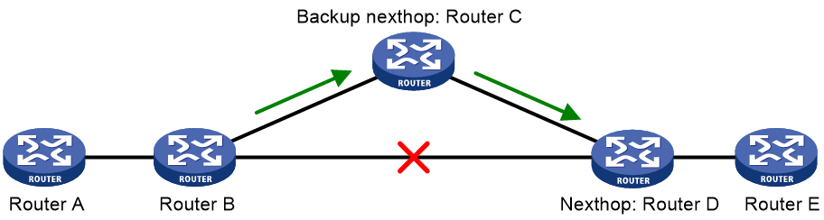
As shown in Figure 1, upon a link failure, packets are directed to the backup next hop to avoid traffic interruption. You can enable FRR to automatically select a backup next hop (which must be configured in advance).
Restrictions and guidelines for IPv6 static route FRR
Do not use IPv6 static route FRR and BFD (for an IPv6 static route) at the same time.
Equal-cost routes do not support IPv6 static route FRR.
Besides the configured IPv6 static route for FRR, the device must have another route to reach the destination. When the state of the primary link (with Layer 3 interfaces staying up) changes from bidirectional to unidirectional or down, IPv6 static route FRR quickly redirects traffic to the backup next hop. When the Layer 3 interfaces of the primary link are down, IPv6 static route FRR temporarily redirects traffic to the backup next hop. In addition, the device searches for another route to reach the destination and redirects traffic to the new path if a route is found. If no route is found, traffic interruption occurs.
Configuring IPv6 static route FRR to automatically select a backup next hop
1. Enter system view.
system-view
2. Configure IPv6 static route FRR to automatically select a backup next hop.
ipv6 route-static fast-reroute auto
By default, IPv6 static route FRR is disabled from automatically selecting a backup next hop.
Enabling BFD echo packet mode for IPv6 static route FRR
About this task
By default, IPv6 static route FRR uses IPv6 ND to detect primary link failures. For quicker IPv6 static route FRR, use BFD echo packet mode on the primary link of redundant links to detect link failure.
Procedure
1. Enter system view.
system-view
2. (Optional.) Configure the source IP address of BFD echo packets.
bfd echo-source-ipv6 ipv6-address
By default, the source IPv6 address of BFD echo packets is not configured.
As a best practice to avoid network congestion caused by excessive ICMPv6 redirect packets from the peer, use this command. Make sure the source IPv6 address is not on the subnet of any interfaces on the device.
You must specify a global unicast address as the source IPv6 address of BFD echo packets.
For more information about this command, see BFD commands in High Availability Command Reference.
3. Enable BFD echo packet mode for IPv6 static route FRR.
ipv6 route-static primary-path-detect bfd echo
By default, BFD echo packet mode is disabled for IPv6 static route FRR.
Display and maintenance commands for IPv6 static routing
Execute display commands in any view.
|
Task |
Command |
|
Display IPv6 static route next hop information. |
display ipv6 route-static nib [ nib-id ] [ verbose ] |
|
Display IPv6 static routing table information. |
display ipv6 route-static routing-table [ vpn-instance vpn-instance-name ] [ ipv6-address prefix-length ] |
|
Display IPv6 static route information. |
display ipv6 routing-table protocol static [ inactive | verbose ] |
For more information about the display ipv6 routing-table protocol static [ inactive | verbose ] command, see basic IP routing in Layer 3—IP Routing Command Reference.
IPv6 static routing configuration examples
Example: Configuring basic IPv6 static route
Network configuration
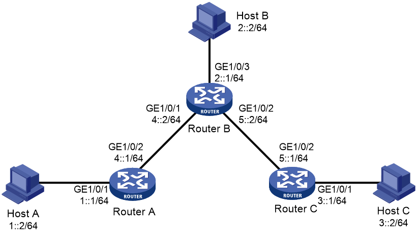
As shown in Figure 2, configure IPv6 static routes so that hosts can reach each other.
Procedure
1. Configure IPv6 addresses for interfaces. (Details not shown.)
2. Configure IPv6 static routes:
# Configure the default IPv6 route on Router A.
<RouterA> system-view
[RouterA] ipv6 route-static :: 0 4::2
# Configure two IPv6 static routes on Router B.
<RouterB> system-view
[RouterB] ipv6 route-static 1:: 64 4::1
[RouterB] ipv6 route-static 3:: 64 5::1
# Configure the default IPv6 route on Router C.
<RouterC> system-view
[RouterC] ipv6 route-static :: 0 5::2
3. Configure the IPv6 addresses for all hosts and configure the default gateway of Host A, Host B, and Host C as 1::1, 2::1, and 3::1.
Verifying the configuration
# Display the IPv6 static route information on Router A.
[RouterA] display ipv6 routing-table protocol static
Summary Count : 1
Static Routing table Status : <Active>
Summary Count : 1
Destination: :: Protocol : Static
NextHop : 4::2 Preference: 60
Interface : GE1/0/2 Cost : 0
Static Routing table Status : <Inactive>
Summary Count : 0
# Display the IPv6 static route information on Router B.
[RouterB] display ipv6 routing-table protocol static
Summary Count : 2
Static Routing table Status : <Active>
Summary Count : 2
Destination: 1::/64 Protocol : Static
NextHop : 4::1 Preference: 60
Interface : GE1/0/1 Cost : 0
Destination: 3::/64 Protocol : Static
NextHop : 5::1 Preference: 60
Interface : GE1/0/2 Cost : 0
Static Routing table Status : <Inactive>
Summary Count : 0
# Use the ping command to test reachability.
Ping6(56 data bytes) 4::1 --> 3::1, press CTRL_C to break
56 bytes from 3::1, icmp_seq=0 hlim=62 time=0.700 ms
56 bytes from 3::1, icmp_seq=1 hlim=62 time=0.351 ms
56 bytes from 3::1, icmp_seq=2 hlim=62 time=0.338 ms
56 bytes from 3::1, icmp_seq=3 hlim=62 time=0.373 ms
56 bytes from 3::1, icmp_seq=4 hlim=62 time=0.316 ms
--- Ping6 statistics for 3::1 ---
5 packet(s) transmitted, 5 packet(s) received, 0.0% packet loss
round-trip min/avg/max/std-dev = 0.316/0.416/0.700/0.143 ms
Example: Configuring BFD for IPv6 static routes (direct next hop)
Network configuration
As shown in Figure 3:
· Configure an IPv6 static route to subnet 120::/64 on Router A.
· Configure an IPv6 static route to subnet 121::/64 on Router B.
· Enable BFD for both routes.
· Configure an IPv6 static route to subnet 120::/64 and an IPv6 static route to subnet 121::/64 on Router C.
When the link between Router A and Router B through the Layer 2 switch fails, BFD can detect the failure immediately and inform Router A and Router B to communicate through Router C.
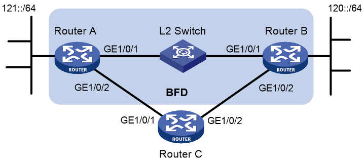
Table 1 Interface and IP address assignment
|
Device |
Interface |
IPv6 address |
|
Router A |
GE1/0/1 |
12::1/64 |
|
Router A |
GE1/0/2 |
10::102/64 |
|
Router B |
GE1/0/1 |
12::2/64 |
|
Router B |
GE1/0/2 |
13::1/64 |
|
Router C |
GE1/0/1 |
10::100/64 |
|
Router C |
GE1/0/2 |
13::2/64 |
Procedure
1. Configure IPv6 addresses for interfaces. (Details not shown.)
2. Configure IPv6 static routes and BFD:
# Configure IPv6 static routes on Router A, and enable BFD control packet mode for the IPv6 static route that traverses GigabitEthernet 1/0/1.
<RouterA> system-view
[RouterA] interface gigabitethernet 1/0/1
[RouterA-GigabitEthernet1/0/1] bfd min-transmit-interval 500
[RouterA-GigabitEthernet1/0/1] bfd min-receive-interval 500
[RouterA-GigabitEthernet1/0/1] bfd detect-multiplier 9
[RouterA-GigabitEthernet1/0/1] quit
[RouterA] ipv6 route-static 120:: 64 gigabitethernet 1/0/1 12::2 bfd control-packet
[RouterA] ipv6 route-static 120:: 64 10::100 preference 65
[RouterA] quit
# Configure IPv6 static routes on Router B, and enable BFD control packet mode for the IPv6 static route that traverses the Layer 2 switch.
<RouterB> system-view
[RouterB] interface gigabitethernet 1/0/1
[RouterB-GigabitEthernet1/0/1] bfd min-transmit-interval 500
[RouterB-GigabitEthernet1/0/1] bfd min-receive-interval 500
[RouterB-GigabitEthernet1/0/1] bfd detect-multiplier 9
[RouterB-GigabitEthernet1/0/1] quit
[RouterB] ipv6 route-static 121:: 64 gigabitethernet 1/0/1 12::1 bfd control-packet
[RouterB] ipv6 route-static 121:: 64 13::2 preference 65
[RouterB] quit
# Configure IPv6 static routes on Router C.
<RouterC> system-view
[RouterC] ipv6 route-static 120:: 64 13::1
[RouterC] ipv6 route-static 121:: 64 10::102
Verifying the configuration
# Display BFD sessions on Router A.
<RouterA> display bfd session
Total sessions: 1 Up sessions: 1 Init mode: Active
IPv6 session working in control packet mode:
Local discr: 513 Remote discr: 33
Source IP: 12::1
Destination IP: 12::2
Session state: Up Interface: GE1/0/1
Hold time: 2012ms
The output shows that the BFD session has been created.
# Display IPv6 static routes on Router A.
<RouterA> display ipv6 routing-table protocol static
Summary Count : 1
Static Routing table Status : <Active>
Summary Count : 1
Destination: 120::/64 Protocol : Static
NextHop : 12::2 Preference: 60
Interface : GE1/0/1 Cost : 0
Static Routing table Status : <Inactive>
Summary Count : 0
The output shows that Router A communicates with Router B through GigabitEthernet 1/0/1. The link over GigabitEthernet 1/0/1 fails.
# Display IPv6 static routes on Router A.
<RouterA> display ipv6 routing-table protocol static
Summary Count : 1
Static Routing table Status : <Active>
Summary Count : 1
Destination: 120::/64 Protocol : Static
NextHop : 10::100 Preference: 65
Interface : GE1/0/2 Cost : 0
Static Routing table Status : <Inactive>
Summary Count : 0
The output shows that Router A communicates with Router B through GigabitEthernet 1/0/2.
Example: Configuring BFD for IPv6 static routes (indirect next hop)
Network configuration
As shown in Figure 4:
· Router A has a route to interface Loopback 1 (2::9/128) on Router B, and the output interface is GigabitEthernet 1/0/1.
· Router B has a route to interface Loopback 1 (1::9/128) on Router A, and the output interface is GigabitEthernet 1/0/1.
· Router D has a route to 1::9/128, and the output interface is GigabitEthernet 1/0/1. It also has a route to 2::9/128, and the output interface is GigabitEthernet 1/0/2.
Configure the following:
· Configure an IPv6 static route to subnet 120::/64 on Router A.
· Configure an IPv6 static route to subnet 121::/64 on Router B.
· Enable BFD for both routes.
· Configure an IPv6 static route to subnet 120::/64 and an IPv6 static route to subnet 121::/64 on both Router C and Router D.
When the link between Router A and Router B through Router D fails, BFD can detect the failure immediately and Router A and Router B can communicate through Router C.
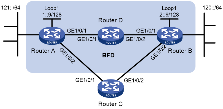
Table 2 Interface and IP address assignment
|
Device |
Interface |
IPv6 address |
|
Router A |
GE1/0/1 |
12::1/64 |
|
Router A |
GE1/0/2 |
10::102/64 |
|
Router A |
Loop1 |
1::9/128 |
|
Router B |
GE1/0/1 |
11::2/64 |
|
Router B |
GE1/0/2 |
13::1/64 |
|
Router B |
Loop1 |
2::9/128 |
|
Router C |
GE1/0/1 |
10::100/64 |
|
Router C |
GE1/0/2 |
13::2/64 |
|
Router D |
GE1/0/1 |
12::2/64 |
|
Router D |
GE1/0/2 |
11::1/64 |
Procedure
1. Configure IPv6 addresses for interfaces. (Details not shown.)
2. Configure IPv6 static routes and BFD:
# Configure IPv6 static routes on Router A and enable BFD control packet mode for the IPv6 static route that traverses Router D.
<RouterA> system-view
[RouterA] bfd multi-hop min-transmit-interval 500
[RouterA] bfd multi-hop min-receive-interval 500
[RouterA] bfd multi-hop detect-multiplier 9
[RouterA] ipv6 route-static 120:: 64 2::9 bfd control-packet bfd-source 1::9
[RouterA] ipv6 route-static 120:: 64 10::100 preference 65
[RouterA] ipv6 route-static 2::9 128 12::2
[RouterA] quit
# Configure IPv6 static routes on Router B and enable BFD control packet mode for the IPv6 static route that traverses Router D.
<RouterB> system-view
[RouterB] bfd multi-hop min-transmit-interval 500
[RouterB] bfd multi-hop min-receive-interval 500
[RouterB] bfd multi-hop detect-multiplier 9
[RouterB] ipv6 route-static 121:: 64 1::9 bfd control-packet bfd-source 2::9
[RouterB] ipv6 route-static 121:: 64 13::2 preference 65
[RouterB] ipv6 route-static 1::9 128 11::1
[RouterB] quit
# Configure IPv6 static routes on Router C.
<RouterC> system-view
[RouterC] ipv6 route-static 120:: 64 13::1
[RouterC] ipv6 route-static 121:: 64 10::102
# Configure IPv6 static routes on Router D.
<RouterD> system-view
[RouterD] ipv6 route-static 120:: 64 11::2
[RouterD] ipv6 route-static 121:: 64 12::1
[RouterD] ipv6 route-static 2::9 128 11::2
[RouterD] ipv6 route-static 1::9 128 12::1
Verifying the configuration
# Display BFD sessions on Router A.
<RouterA> display bfd session
Total sessions: 1 Up sessions: 1 Init mode: Active
IPv6 session working in control packet mode:
Local discr: 513 Remote discr: 33
Source IP: 1::9
Destination IP: 2::9
Session state: Up Interface: N/A
Hold time: 2012ms
The output shows that the BFD session has been created.
# Display IPv6 static routes on Router A.
<RouterA> display ipv6 routing-table protocol static
Summary Count : 1
Static Routing table Status : <Active>
Summary Count : 1
Destination: 120::/64 Protocol : Static
NextHop : 2::9 Preference: 60
Interface : GE1/0/1 Cost : 0
Static Routing table Status : <Inactive>
Summary Count : 0
The output shows that Router A communicates with Router B through GigabitEthernet 1/0/1. The link over GigabitEthernet 1/0/1 fails.
# Display IPv6 static routes on Router A.
<RouterA> display ipv6 routing-table protocol static
Summary Count : 1
Static Routing table Status : <Active>
Summary Count : 1
Destination: 120::/64 Protocol : Static
NextHop : 10::100 Preference: 65
Interface : GE1/0/2 Cost : 0
Static Routing table Status : <Inactive>
Summary Count : 0
The output shows that Router A communicates with Router B through GigabitEthernet 1/0/2.
Example: Configuring IPv6 static route FRR
Network configuration
As shown in Figure 5, configure IPv6 static routes on Router A, Router B, and Router C, and configure IPv6 static route FRR. When Link A becomes unidirectional, traffic can be switched to Link B immediately.
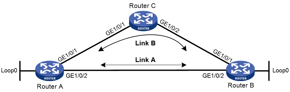
Table 3 Interface and IP address assignment
|
Device |
Interface |
IP address |
|
Router A |
GE1/0/1 |
13::1/64 |
|
Router A |
GE1/0/2 |
12::1/64 |
|
Router A |
Loopback 0 |
1::9/128 |
|
Router B |
GE1/0/1 |
23::2/64 |
|
Router B |
GE1/0/2 |
12::2/64 |
|
Router B |
Loopback 0 |
2::9/128 |
|
Router C |
GE1/0/1 |
13::3/64 |
|
Router C |
GE1/0/2 |
23::3/64 |
Procedure
1. Configure IPv6 addresses for interfaces. (Details not shown.)
2. Configure IPv6 static route FRR to automatically select a backup next hop:
# Configure IPv6 static routes on Router A, and configure IPv6 static route FRR to automatically select a backup next hop.
<RouterA> system-view
[RouterA] ipv6 route-static 2::9 128 gigabitethernet 1/0/2 12::2
[RouterA] ipv6 route-static 2::9 128 gigabitethernet 1/0/1 13::3 preference 70
[RouterA] ipv6 route-static 23:: 64 gigabitethernet 1/0/2 12::2
[RouterA] ipv6 route-static 23:: 64 gigabitethernet 1/0/1 13::3 preference 70
[RouterA] ipv6 route-static fast-reroute auto
# Configure IPv6 static routes on Router B, and configure IPv6 static route FRR to automatically select a backup next hop.
<RouterB> system-view
[RouterB] ipv6 route-static 1::9 128 gigabitethernet 1/0/2 12::1
[RouterB] ipv6 route-static 1::9 128 gigabitethernet 1/0/1 23::3 preference 70
[RouterB] ipv6 route-static 13:: 64 gigabitethernet 1/0/2 12::1
[RouterB] ipv6 route-static 13:: 64 gigabitethernet 1/0/1 23::3 preference 70
[RouterB] ipv6 route-static fast-reroute auto
3. Configure IPv6 static routes on Router C.
<RouterC> system-view
[RouterC] ipv6 route-static 1::9 128 gigabitethernet 1/0/1 13::1
[RouterC] ipv6 route-static 2::9 128 gigabitethernet 1/0/2 23::2
Verifying the configuration
# Display route 2::9/128 on Router A to view the backup next hop information.
[RouterA] display ipv6 routing-table 2::9 verbose
Summary Count : 1
Destination: 2::9/128
Protocol: Static
Process ID: 0
SubProtID: 0x1 Age: 00h09m12s
Cost: 0 Preference: 60
IpPre: N/A QosLocalID: N/A
Tag: 0 State: Active Adv
OrigTblID: 0x0 OrigVrf: default-vrf
TableID: 0xa OrigAs: 0
NibID: 0x21000002 LastAs: 0
AttrID: 0xffffffff Neighbor: ::
Flags: 0x10040 OrigNextHop: 12::2
Label: NULL RealNextHop: 12::2
BkLabel: NULL BkNextHop: 13::3
SRLabel: NULL Interface: GigabitEthernet1/0/2
BkSRLabel: NULL BkInterface: GigabitEthernet1/0/1
SIDIndex: NULL InLabel: NULL
Tunnel ID: Invalid IPInterface: GigabitEthernet1/0/2
BkTunnel ID: Invalid BkIPInterface: GigabitEthernet1/0/1
FtnIndex: 0x0 ColorInterface: N/A
TrafficIndex: N/A BkColorInterface: N/A
Connector: N/A VpnPeerId: N/A
Dscp: N/A Exp: N/A
SRTunnelID: Invalid StatFlags: 0x0
SID Type: N/A SID: N/A
BkSID: N/A NID: Invalid
FlushNID: Invalid BkNID: Invalid
BkFlushNID: Invalid PathID: 0x0
CommBlockLen: 0
OrigLinkID: 0x0 RealLinkID: 0x0
# Display route 1::9/128 on Router B to view the backup next hop information.
[RouterB] display ipv6 routing-table 1::9 verbose
Summary Count : 1
Destination: 1::9/128
Protocol: Static
Process ID: 0
SubProtID: 0x1 Age: 00h09m57s
Cost: 0 Preference: 60
IpPre: N/A QosLocalID: N/A
Tag: 0 State: Active Adv
OrigTblID: 0x0 OrigVrf: default-vrf
TableID: 0xa OrigAs: 0
NibID: 0x21000002 LastAs: 0
AttrID: 0xffffffff Neighbor: ::
Flags: 0x10040 OrigNextHop: 12::1
Label: NULL RealNextHop: 12::1
BkLabel: NULL BkNextHop: 23::3
SRLabel: NULL Interface: GigabitEthernet1/0/2
BkSRLabel: NULL BkInterface: GigabitEthernet1/0/1
SIDIndex: NULL InLabel: NULL
Tunnel ID: Invalid IPInterface: GigabitEthernet1/0/2
BkTunnel ID: Invalid BkIPInterface: GigabitEthernet1/0/1
FtnIndex: 0x0 ColorInterface: N/A
TrafficIndex: N/A BkColorInterface: N/A
Connector: N/A VpnPeerId: N/A
Dscp: N/A Exp: N/A
SRTunnelID: Invalid StatFlags: 0x0
SID Type: N/A SID: N/A
BkSID: N/A NID: Invalid
FlushNID: Invalid BkNID: Invalid
BkFlushNID: Invalid PathID: 0x0
CommBlockLen: 0
OrigLinkID: 0x0 RealLinkID: 0x0
Configuring an IPv6 default route
A default IPv6 route is used to forward packets that match no entry in the routing table.
A default IPv6 route can be configured in either of the following ways:
· The network administrator can configure a default route with a destination prefix of ::/0. For more information, see "Configuring IPv6 static routing."
· Some dynamic routing protocols (such as OSPFv3, IPv6 IS-IS, and RIPng) can generate a default IPv6 route. For example, an upstream router running OSPFv3 can generate a default IPv6 route and advertise it to other routers. These routers install the default IPv6 route with the next hop being the upstream router. For more information, see the respective chapters on those routing protocols in this configuration guide.
As shown in Figure 6, Device B is the next hop for packets from Device A to Device C, Device D, and Device E. You can configure a default route on Device A to replace the three IPv6 static routes from Device A to Device C, Device D, and Device E.
Configure the IPv6 default route as follows:
· Configure the next hop address as 1::2.
· Configure the destination address as ::.
· Configure the prefix length as 0.
Figure 6 Configuring an IPv6 default route

