- Table of Contents
-
- 01-Fundamentals Configuration Guide
- 00-Preface
- 01-CLI configuration
- 02-RBAC configuration
- 03-Login management configuration
- 04-FTP and TFTP configuration
- 05-File system management configuration
- 06-Configuration file management configuration
- 07-Software upgrade configuration
- 08-Emergency shell configuration
- 09-Automatic configuration
- 10-Device management configuration
- 11-Tcl configuration
- 12-Python configuration
- 13-License management
- 14-RAID management configuration
- 15-Preprovisioning feature configuration
- Related Documents
-
| Title | Size | Download |
|---|---|---|
| 09-Automatic configuration | 247.52 KB |
Contents
Using server-based automatic configuration
About server-based automatic configuration
Server-based automatic configuration tasks at a glance
Preparing the interface used for automatic configuration
Starting and completing automatic configuration
Using URL-based automatic configuration
About URL-based automatic configuration
Restrictions: Hardware compatibility with URL-based automatic configuration
How URL-based automatic configuration works
Using USB-based automatic configuration
About USB-based automatic configuration
Preparing the USB disk for automatic configuration
Configuring and using USB-based automatic configuration
Using SMS-based automatic configuration
About SMS-based automatic configuration
SMS-based automatic configuration tasks at a glance
Prerequisites for SMS-based automatic configuration
Enabling SMS-based automatic configuration on the device
Configuring the IMC server and using a cell phone to trigger automatic configuration
Configuring the IMC server and using the IMC server to trigger automatic configuration
Verifying and completing SMS-based automatic configuration
Public cloud-based automatic configuration
Server-based automatic configuration examples
Example: Using a TFTP server for automatic configuration
Example: Using an HTTP server and Tcl scripts for automatic configuration
Example: Using an HTTP server and Python scripts for automatic configuration
Example: Setting up an IRF fabric
Using automatic configuration
About automatic configuration
With the automatic configuration feature, the device can automatically obtain a set of configuration settings at startup. This feature simplifies network configuration and maintenance.
Automatic configuration can be implemented by using the implementation methods in Table 1.
Table 1 Automatic configuration implementation methods
|
Implementation method |
Configuration file location |
Application scenarios |
|
Server-based automatic configuration |
File server |
A number of geographically distributed devices need to be configured. |
|
URL-based automatic configuration |
Saved on the device before the device is shipped |
Devices are geographically distributed. |
|
USB-based automatic configuration |
USB disk |
· On a small network, the devices reside near to each other, and no host can be used as a file server. · On a large network, only a few devices require automatic configuration or configuration update. |
|
SMS-based automatic configuration |
IMC server |
The devices to be configured are geographically distributed. A 3G or 4G network is available. |
If both server-based automatic configuration and USB-based automatic configuration are available, the device prefers USB-based automatic configuration.
As a best practice, use SMS-based automatic configuration only if you do not have any other choices. SMS-based automatic configuration has the following disadvantages:
· High cost.
· Low reliability. Short messages depend on 3G or 4G networks. Wireless signals might be unstable.
Using server-based automatic configuration
About server-based automatic configuration
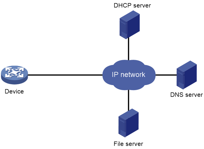
As shown in Figure 1, server-based automatic configuration requires the following servers:
· DHCP server.
· File server (TFTP or HTTP server).
· (Optional.) DNS server.
Figure 1 Server-based automatic configuration network diagram
Server-based automatic configuration tasks at a glance
To configure server-based automatic configuration, perform the following tasks:
1. Configuring the file server
2. Prepare the files for automatic configuration:
¡ Preparing configuration files
3. Configuring the DHCP server
4. (Optional.) Configuring the DNS server
5. (Optional.) Configuring the gateway
6. Preparing the interface used for automatic configuration
7. Starting and completing automatic configuration
Configuring the file server
For devices to obtain configuration information from a TFTP server, start TFTP service on the file server.
For devices to obtain configuration information from an HTTP server, start HTTP service on the file server.
Preparing configuration files
Configuration file types
The device supports the configuration file types listed in Table 2.
Table 2 Configuration file types
|
Configuration file type |
Application objects |
File name requirements |
Supported file server types |
|
Dedicated configuration file |
Devices that require different settings |
File name.cfg For simple file name identification, use configuration file names that do not contain spaces. |
· TFTP server · HTTP server |
|
Common configuration file |
Devices that share all or some settings |
File name.cfg |
· TFTP server · HTTP server |
|
Default configuration file |
Other devices. The file contains only common configurations that devices use to start up. |
device.cfg |
TFTP server |
Identifying requirements for and preparing configuration files
1. Identify the requirements of the devices for configuration files.
2. For devices that require different configurations, prepare a configuration file for each of them and save the files to the file server.
3. For devices that share all or some configurations, save the common configurations to a .cfg file on the file server.
4. If a TFTP file server is used, you can save the common configurations that devices use to start up to the device.cfg file on the server. The file is assigned to a device only when the device does not have any other configuration file to use.
Preparing the host name file on the TFTP server
If a TFTP server is used and the DHCP server does not assign configuration file names, you can configure a host name file on the TFTP server. The host name file contains the host name-IP address mappings of the devices to be automatically configured.
To prepare the host name file:
1. Create a host name file named network.cfg.
2. Add each mapping entry in the ip host host-name ip-address format on a separate line. For example:
ip host host1 101.101.101.101
ip host host2 101.101.101.102
ip host client1 101.101.101.103
ip host client2 101.101.101.104
|
|
IMPORTANT: The host name for a device must be the same as the name of the configuration file configured for the device. |
Preparing script files
About this task
Script files can be used for automatic software upgrade and automatic configuration.
The device supports Python scripts (.py files) and Tcl scripts (.tcl files). For more information about Python and Tcl scripts, see "Using Python" and "Using Tcl."
The device supports dedicated script files and common dedicated script files. It does not support using a default script file. For information about dedicated script files and common dedicated script files, see Table 2.
When script files are used, you cannot use a host name file to provide the host name-IP address mappings for devices.
Restrictions and guidelines
To use a Tcl script, make sure all commands in the script are supported and correctly configured. Any error in a command causes the automatic configuration process to quit.
Procedure
· For devices that share all or some configurations, create a script file that contains the common configurations.
· For the other devices, create a separate script file for each of them.
Configuring the DHCP server
About this task
The DHCP server assigns the following items to devices that need to be automatically configured:
· IP addresses.
· Paths of the configuration or script files.
Restrictions and guidelines
When you configure the DHCP server, follow these guidelines:
· For devices for which you have prepared different configuration files, perform the following tasks for each of the devices on the DHCP server:
¡ Create a DHCP address pool.
¡ Configure a static address binding.
¡ Specify a configuration file or script file.
Because an address pool can use only one configuration file, you can specify only one static address binding for an address pool.
· For devices for which you have prepared the same configuration file, use either of the following methods:
¡ Method 1:
- Create a DHCP address pool for the devices.
- Configure a static address binding for each of the devices in the address pool.
- Specify the configuration file for the devices.
¡ Method 2:
- Create a DHCP address pool for the devices.
- Specify the subnet for dynamic allocation.
- Specify the TFTP server.
- Specify the configuration file for the devices.
· If all devices on a subnet share the same configuration file or script file, perform the following tasks on the DHCP server:
¡ Configure dynamic address allocation.
¡ Specify the configuration file or script file for the devices.
The configuration file can contain only the common settings for the devices. You can provide a method for the device administrators to change the configurations after their devices start up.
Configuring the DHCP server when an HTTP file server is used
1. Enter system view.
system-view
2. Enable DHCP.
dhcp enable
By default, DHCP is disabled.
3. Create a DHCP address pool and enter its view.
dhcp server ip-pool pool-name
4. Configure the address pool.
Choose the options to configure as needed:
¡ Specify the primary subnet for the address pool.
network network-address [ mask-length | mask mask ]
By default, no primary subnet is specified.
¡ Configure a static binding.
static-bind ip-address ip-address [ mask-length | mask mask ] { client-identifier client-identifier | hardware-address hardware-address [ ethernet | token-ring ] }
By default, no static binding is configured.
You can configure multiple static bindings. However, one IP address can be bound to only one client. To change the binding for a DHCP client, you must remove the binding and reconfigure a binding.
5. Specify the URL of the configuration or script file.
bootfile-name url
By default, no configuration or script file URL is specified.
Configuring the DHCP server when a TFTP file server is used
1. Enter system view.
system-view
2. Enable DHCP.
dhcp enable
By default, DHCP is disabled.
3. Create a DHCP address pool and enter its view.
dhcp server ip-pool pool-name
4. Configure the address pool.
Choose the options to configure as needed:
¡ Specify the primary subnet for the address pool.
network network-address [ mask-length | mask mask ]
By default, no primary subnet is specified.
¡ Configure a static binding.
static-bind ip-address ip-address [ mask-length | mask mask ] { client-identifier client-identifier | hardware-address hardware-address [ ethernet | token-ring ] }
By default, no static binding is configured.
You can configure multiple static bindings. However, one IP address can be bound to only one client. To change the binding for a DHCP client, you must remove the binding and reconfigure a binding.
5. Specify a TFTP server.
Choose one option as needed:
¡ Specify the IP address of the TFTP server.
tftp-server ip-address ip-address
By default, no TFTP server IP address is specified.
¡ Specify the name of the TFTP server.
tftp-server domain-name domain-name
By default, no TFTP server name is specified.
If you specify a TFTP server by its name, a DNS server is required on the network.
6. Specify the name of the configuration or script file.
bootfile-name bootfile-name
By default, no configuration or script file name is specified.
Configuring the DNS server
A DNS server is required in the following situations:
· The TFTP server does not have a host name file.
Devices need to provide the DNS server with their IP addresses to obtain their host names. Then, the devices can obtain configuration files named in the host name.cfg format from the TFTP server.
· The DHCP server assigns the TFTP server domain name through the DHCP reply message. Devices must use the domain name to obtain the IP address of the TFTP server.
Configuring the gateway
If the devices to be automatically configured and the servers for automatic configuration reside in different network segments, you must perform the following tasks:
· Deploy a gateway and make sure the devices can communicate with the servers.
· Configure the DHCP relay agent feature on the gateway.
· Configure the UDP helper feature on the gateway.
This task is required if devices send requests to a TFTP server by using broadcast packets. A device uses broadcast packets to send requests to a TFTP server in the following situations:
¡ The DHCP reply does not contain the IP address or domain name of the TFTP server.
¡ The IP address or domain name of the TFTP server is invalid.
The UDP helper transforms a broadcast packet into a unicast packet and forwards the unicast packet to the file server. For more information about UDP helper, see Layer 3—IP Services Configuration Guide.
Preparing the interface used for automatic configuration
The device selects the interface for automatic configuration as follows:
1. Identifies the status of the management Ethernet interface at Layer 2. If the status is up, the device uses the management Ethernet interface.
2. Identifies the status of Layer 2 Ethernet interfaces. If one or more Layer 2 Ethernet interfaces are in up state, the device uses the VLAN interface of the default VLAN.
3. Sorts all Layer 3 Ethernet interfaces in up state first in lexicographical order of interface types and then in ascending order of interface numbers. Uses the interface with the smallest interface number among the interfaces of the first interface type.
4. If no Layer 3 Ethernet interfaces are in up state, the device waits 30 seconds and goes to step 1 to try again.
For fast automatic device configuration, connect only the management Ethernet interface on each device to the network.
Starting and completing automatic configuration
1. Power on the devices to be automatically configured.
If a device does not find a next-start configuration file locally, it starts the automatic configuration process to obtain a configuration file.
¡ If the device obtains a configuration file and executes the file successfully, the automatic configuration process ends.
¡ If one attempt fails, the device tries again until the maximum number of attempts is reached. To stop the process, press Ctrl+C or Ctrl+D.
If the device fails to obtain a configuration file, the device starts up without loading any configuration.
2. Save the running configuration.
save
The device does not save the obtained configuration file locally. If you do not save the running configuration, the device must use the automatic configuration feature again after a reboot.
For more information about the save command, see Fundamentals Command Reference.
Using URL-based automatic configuration
About URL-based automatic configuration
URL-based automatic configuration uses a customizable configuration file saved on the device by default to implement basic device configuration after the device starts up. The configuration file contains the basic network configuration command lines. This feature requires you to construct a URL to indicate the values for the parameters in the command lines. The URL can be in either of the following forms:
· Plaintext form—The user directly configures the plaintext URL. Parameters in the URL are configured and transmitted in plaintext form.
· Encrypted form—The administrator generates the encrypted URL and an authentication password for the URL by using the controller. Within the validity of the URL, a user can enter the authentication password as prompted to use the URL to perform URL-based automatic configuration.
Restrictions: Hardware compatibility with URL-based automatic configuration
|
Hardware |
URL-based automatic configuration compatibility |
|
MSR610 |
Yes |
|
MSR810, MSR810-W, MSR810-W-DB, MSR810-LM, MSR810-W-LM, MSR810-10-PoE, MSR810-LM-HK, MSR810-W-LM-HK, MSR810-LM-CNDE-SJK, MSR810-CNDE-SJK, MSR810-EI, MSR810-LM-EA, MSR810-LM-EI |
Yes |
|
MSR810-LMS, MSR810-LUS |
No |
|
MSR810-SI, MSR810-LM-SI |
No |
|
MSR810-LMS-EA, MSR810-LME |
Yes |
|
MSR1004S-5G, MSR1004S-5G-CN |
Yes |
|
MSR1104S-W, MSR1104S-W-CAT6, MSR1104S-5G-CN, MSR1104S-W-5G-CN |
Yes |
|
MSR2600-6-X1, MSR2600-15-X1, MSR2600-15-X1-T |
Yes |
|
MSR2600-10-X1 |
Yes |
|
MSR 2630 |
Yes |
|
MSR3600-28, MSR3600-51 |
Yes |
|
MSR3600-28-SI, MSR3600-51-SI |
No |
|
MSR3600-28-X1, MSR3600-28-X1-DP, MSR3600-51-X1, MSR3600-51-X1-DP |
Yes |
|
MSR3600-28-G-DP, MSR3600-51-G-DP |
Yes |
|
MSR3610-I-DP, MSR3610-IE-DP, MSR3610-IE-ES, MSR3610-IE-EAD, MSR-EAD-AK770, MSR3610-I-IG, MSR3610-IE-IG |
Yes |
|
MSR3610-X1, MSR3610-X1-DP, MSR3610-X1-DC, MSR3610-X1-DP-DC, MSR3620-X1, MSR3640-X1 |
Yes |
|
MSR 3610, MSR 3620, MSR 3620-DP, MSR 3640, MSR 3660 |
Yes |
|
MSR3610-G, MSR3620-G |
Yes |
|
MSR3640-G |
Yes |
|
MSR3640-X1-HI |
Yes |
|
Hardware |
URL-based automatic configuration compatibility |
|
MSR810-W-WiNet, MSR810-LM-WiNet |
Yes |
|
MSR830-4LM-WiNet |
Yes |
|
MSR830-5BEI-WiNet, MSR830-6EI-WiNet, MSR830-10BEI-WiNet |
Yes |
|
MSR830-6BHI-WiNet, MSR830-10BHI-WiNet |
Yes |
|
MSR2600-6-WiNet |
Yes |
|
MSR2600-10-X1-WiNet |
Yes |
|
MSR2630-WiNet |
Yes |
|
MSR3600-28-WiNet |
Yes |
|
MSR3610-X1-WiNet |
Yes |
|
MSR3610-WiNet, MSR3620-10-WiNet, MSR3620-DP-WiNet, MSR3620-WiNet, MSR3660-WiNet |
Yes |
|
Hardware |
URL-based automatic configuration compatibility |
|
MSR860-6EI-XS |
Yes |
|
MSR860-6HI-XS |
Yes |
|
MSR2630-XS |
Yes |
|
MSR3600-28-XS |
Yes |
|
MSR3610-XS |
Yes |
|
MSR3620-XS |
Yes |
|
MSR3610-I-XS |
Yes |
|
MSR3610-IE-XS |
Yes |
|
MSR3620-X1-XS |
Yes |
|
MSR3640-XS |
Yes |
|
MSR3660-XS |
Yes |
|
Hardware |
URL-based automatic configuration compatibility |
|
MSR810-LM-GL |
Yes |
|
MSR810-W-LM-GL |
Yes |
|
MSR830-6EI-GL |
Yes |
|
MSR830-10EI-GL |
Yes |
|
MSR830-6HI-GL |
Yes |
|
MSR830-10HI-GL |
Yes |
|
MSR1004S-5G-GL |
Yes |
|
MSR2600-6-X1-GL |
Yes |
|
MSR3600-28-SI-GL |
No |
How URL-based automatic configuration works
The basic device configuration defines how the device connects to the network. By default, the following connection modes are available: PPPoE mode, static IP address mode, and DHCP mode. The customizable configuration file contains the command lines for the connection modes. The required URL varies by connection mode.
PPPoE mode
Table 3 lists the parameters required or optional in the URL in PPPoE mode. The following is the format of the URL in PPPoE mode:
http://Device IP address/urlcfg?sys_name=Device name&link_mode=Link mode&dialer_if=Dialer interface name&ntp_server=NTP server (optional)&link_if=WAN interface&ac_host=Server IP address&ac_port=Server port&ac_password=Server password&pap_user=PPPoE PAP authentication password&pap_password=PPPoE PAP authentication password&chap_user=PPPoE CHAP authentication username&chap_password=PPPoE CHAP authentication password
Table 3 Parameters required for PPPoE mode
|
Item |
Parameter |
Value type |
Value range |
Corresponding command |
Required |
|
Device address |
Device IP address |
IP address |
N/A |
N/A |
Yes |
|
Device name |
sys_name |
String |
1 to 64 |
sysname sysname |
Yes |
|
Server address |
ac_host |
IP address |
N/A |
cloud-management server domain ip-address |
Yes |
|
Server port |
ac_port |
Integer |
1 to 65535 |
cloud-management server port port-number |
Yes |
|
Server password |
ac_password |
String |
1 to 63 |
cloud-management server password simple password |
Yes |
|
NTP server |
ntp_server |
IP address |
N/A |
ntp-service unicast-server ip-address |
No |
|
WAN interface |
link_if |
Interface type and number |
N/A |
interface interface-type interface-number |
Yes |
|
PPPoE connection mode |
link_mode |
String |
PPPoE |
N/A |
Yes |
|
PPPoE dialer interface |
dialer_if |
String |
N/A |
interface dialer number |
Yes |
|
PPPoE PAP authentication username |
pap_user |
String |
1 to 80 |
ppp pap local-user user-name password simple password |
Yes |
|
PPPoE PAP authentication password |
pap_password |
String |
1 to 255 |
ppp pap local-user user-name password simple password |
Yes |
|
PPPoE CHAP authentication username |
chap_user |
String |
1 to 80 |
ppp chap user user-name |
Yes |
|
PPPoE CHAP authentication password |
chap_password |
String |
1 to 255 |
ppp chap password simple password |
Yes |
Static IP address mode
Table 4 lists the parameters required or optional in static IP address mode. The following is the format of the URL in static IP address mode:
http://Device IP address/urlcfg?sys_name=Device name&link_mode=Link mode&ntp_server=NTP server (optional)&dest_ip=Destination IP address&dest_mask=Destination IP mask&next_hop=IP address of the next hop&link_if=WAN interface&static_ip=Static IP address&static_mask=Static IP mask&ac_host=Server address&ac_port=Server port&ac_password=Server password
Table 4 Parameters required for static IP address mode
|
Item |
Parameter |
Value type |
Value range |
Corresponding command |
Required |
|
Device address |
Device IP address |
IP address |
N/A |
N/A |
Yes |
|
Device name |
sys_name |
String |
1 to 64 |
sysname sysname |
Yes |
|
Server address |
ac_host |
IP address |
N/A |
cloud-management server domain ip-address |
Yes |
|
Server port |
ac_port |
Integer |
1 to 65535 |
cloud-management server port port-number |
Yes |
|
Server password |
ac_password |
String |
1 to 63 |
cloud-management server password simple password |
Yes |
|
NTP server |
ntp_server |
IP address |
N/A |
ntp-service unicast-server ip-address |
No |
|
Destination IP address |
dest_ip |
IP address |
N/A |
ip route-static dest-address mask next-hop-address |
Yes |
|
Destination IP mask |
dest_mask |
IP mask |
N/A |
ip route-static dest-address mask next-hop-address |
Yes |
|
IP address of the next hop |
next_hop |
IP address |
N/A |
ip route-static dest-address mask next-hop-address |
Yes |
|
WAN interface |
link_if |
Interface type and number |
N/A |
interface interface-type interface-number |
Yes |
|
Static IP address connection mode |
link_mode |
String |
STATIC |
N/A |
Yes |
|
Static IP address |
static_ip |
IP address |
N/A |
ip address ip-address mask |
Yes |
|
Static IP mask |
static_mask |
IP mask |
N/A |
ip address ip-address mask |
Yes |
|
Static default gateway |
gateway |
IP address |
N/A |
ip route-static 0.0.0.0 0.0.0.0 next-hop-address |
Yes |
DHCP mode
Table 5 lists the parameters required or optional in DHCP mode. The following is the format of the URL in DHCP mode:
http://Device IP address/urlcfg?sys_name=Device name&link_mode=Link mode&ntp_server=NTP server (optional)&link_if=WAN interface&ac_host=Server address&ac_port=Server port&ac_password=Server password
Table 5 Parameters required for DHCP mode
|
Item |
Parameter |
Value type |
Value range |
Corresponding command |
Required |
|
Device address |
Device IP address |
IP address |
N/A |
N/A |
Yes |
|
Device name |
sys_name |
String |
1 to 64 |
sysname sysname |
Yes |
|
Server address |
ac_host |
IP address |
N/A |
cloud-management server domain ip-address |
Yes |
|
Server port |
ac_port |
Integer |
1 to 65535 |
cloud-management server port port-number |
Yes |
|
Server password |
ac_password |
String |
1 to 63 |
cloud-management server password simple password |
Yes |
|
NTP server |
ntp_server |
IP address |
N/A |
ntp-service unicast-server ip-address |
No |
|
WAN interface |
link_if |
Interface type and number |
N/A |
interface interface-type interface-number |
Yes |
|
DHCP connection mode |
link_mode |
String |
DHCP |
N/A |
Yes |
Procedure
1. Power on the device.
2. Enable URL-based automatic configuration.
a. Enter system view.
system-view
b. Enable URL-based automatic configuration.
autodeploy url enable
By default, URL-based automatic configuration is enabled the state.
c. Save the current configuration.
save
A device reboot is required for URL-based automatic configuration. Save the running configuration to ensure that the URL-based automatic configuration feature takes effect after a reboot.
3. On the configuration terminal, launch a Web browser and enter the default IP address of the device in the address bar. Then, enter the default username and password as prompted to log in to the device.
You can change the default IP address, username, and password on the device. The IP address and username are the device address and device name required in the URL.
4. Construct a URL as describe in "How URL-based automatic configuration works."
5. Enter the URL in the address bar and enter the username and password as prompted.
The device will use the parameters and values in the URL and the customizable configuration file to reconstruct a configuration file, and then execute the file to complete automatic configuration.
Configuration file
|
|
IMPORTANT: The contents of the configuration file might vary by device model. |
PPPoE mode section
{link_mode = PPPoE}
#
system-view
#
sysname [sys_name]
#
dialer-group 1 rule ip permit
#
interface Dialer1
1:ppp chap password simple [chap_password]
1:ppp chap user [chap_user]
ppp ipcp dns admit-any
ppp ipcp dns request
1:ppp pap local-user [pap_user] password simple [pap_password]
dialer bundle enable
dialer-group 1
dialer timer idle 0
dialer timer autodial 5
ip address ppp-negotiate
tcp mss 1024
nat outbound
#
quit
#
interface [link_if]
port link-mode route
pppoe-client dial-bundle-number 1
#
quit
#
1:ntp-service unicast-server [ntp_server]
#
cloud-management server domain [ac_host]
cloud-management server port [ac_port]
cloud-management server password simple [ac_password]
#
ip route-static 0.0.0.0 0 Dialer1
#
Static IP address mode section
{link_mode = STATIC}
#
system-view
#
sysname [sys_name]
#
interface [link_if]
port link-mode route
ip address [static_ip] [static_mask]
nat outbound
#
qu
#
1:ntp-service unicast-server [ntp_server]
#
cloud-management server domain [ac_host]
cloud-management server port [ac_port]
cloud-management server password simple [ac_password]
#
ip route-static 0.0.0.0 0.0.0.0 [gateway]
#
DHCP mode section
{link_mode = DHCP}
#
system-view
#
sysname [sys_name]
#
interface [link_if]
port link-mode route
ip address dhcp-alloc
nat outbound
#
qu
#
1:ntp-service unicast-server [ntp_server]
#
cloud-management server domain [ac_host]
cloud-management server port [ac_port]
cloud-management server password simple [ac_password]
#
Using USB-based automatic configuration
About USB-based automatic configuration
USB-based automatic configuration enables the device to obtain a configuration file from a connected USB disk at startup. The configuration file can be in either of the following forms:
· Plaintext form—The configuration file is saved in plaintext form.
· Encrypted form—The configuration file is generated by the administrator in encrypted form by using the controller. When being transmitted to a USB disk, the configuration data in the file is transmitted in encrypted form. When being used to perform automatic configuration, the configuration data is automatically decrypted by the device.
After obtaining a configuration file, the device compares the file with its main startup configuration file. If the two files have the same settings, the device loads its main startup configuration file. If the two files have different settings, the device performs the following operations:
1. Identifies whether its main startup configuration file is using the same name as the obtained configuration file.
¡ If yes, the device renames its main startup configuration file by adding _bak to the base name of the file, and copies the obtained configuration file.
¡ If not, the system uses the obtained configuration file to overwrite its main startup configuration file.
2. Loads the obtained configuration file.
¡ If all commands in the obtained configuration file are successfully loaded, the device sets the obtained configuration file as the main startup configuration file.
¡ If a command in the obtained configuration file fails, the device removes all loaded settings
and searches for a local configuration file.
- If a configuration file is found, the device loads the configuration file.
- If no configuration file is found, the device finishes the automatic configuration process without loading any configurations.
Preparing the USB disk for automatic configuration
1. Prepare a USB disk that has only one partition.
2. Display the serial number of the device.
display device manuinfo
For more information about this command, see Fundamentals Command Reference.
3. Create a configuration file named Device serial number.cfg or autodeploy.cfg, and save the file to the root directory of the file system on the USB disk.
If a configuration file named Device serial number.cfg coexists with configuration file autodeploy.cfg, configuration file Device serial number.cfg is used.
Configuring and using USB-based automatic configuration
1. Enable USB-based automatic configuration on the device:
a. Enter system view.
system-view
b. Enable USB-based automatic configuration.
autodeploy udisk enable
By default, USB-based automatic configuration is enabled.
c. Save the running configuration.
save
A device reboot is required for USB-based automatic configuration. Save the running configuration to ensure that the USB-based automatic configuration feature takes effect after a reboot.
2. Connect the USB disk to the USB1 interface on the device.
The USB disk will be identified as usba0.
3. Reboot the device and observe the LEDs of the device.
If the device finds no configuration files to load at startup, it performs the following operations:
a. Copies the configuration file on the USB disk.
b. Specifies the file as the startup configuration file.
c. Reboots to load the configuration file.
¡ If the SYS LED flashes green quickly for 5 seconds, the automatic configuration succeeded. Proceed to step 5.
¡ If the SYS LED flashes yellow quickly for 10 seconds, the automatic configuration failed. Display the log file named Fully qualified configuration file name.log in the USB disk root directory to locate and resolve the problem.
For more information about the LEDs, see the installation guide.
4. If the automatic configuration succeeded, use the display current-configuration command to verify that the configuration file has been loaded correctly.
5. Remove the USB disk to make sure the device does not start USB-based automatic configuration at the next reboot.
6. If you removed one MPU previously, install the MPU.
The MPU automatically synchronizes its configuration with the active MPU at startup.
Using SMS-based automatic configuration
About SMS-based automatic configuration
With SMS-based automatic configuration, the device can connect to an IMC server over a 3G or 4G network to obtain a configuration file.
The SMS-based automatic configuration process requires a short message to trigger. The short message can come from one of the following sources:
· A cell phone.
· The IMC server. The IMC server sends short messages to devices through an SMS gateway.
SMS-based automatic configuration tasks at a glance
To configure SMS-based automatic configuration, perform the following tasks:
1. Enabling SMS-based automatic configuration on the device
2. Configuring the IMC server and using a cell phone or the IMC server to trigger automatic configuration:
¡ Configuring the IMC server and using a cell phone to trigger automatic configuration
¡ Configuring the IMC server and using the IMC server to trigger automatic configuration
3. Verifying and completing SMS-based automatic configuration
Prerequisites for SMS-based automatic configuration
1. Verify that the device to be configured has a 3G or 4G modem module. Make sure the modem module has a 3G or 4G SIM card installed and the SIM card account balance is sufficient.
If the modem uses a USB interface, you can install the modem to a PC to test whether you can use the modem to connect to the 3G or 4G network correctly.
2. To use an SMS gateway, verify that the IMC server and the SMS gateway can reach each other.
3. On the device to be automatically configured, assign an IP address to a loopback interface.
Enabling SMS-based automatic configuration on the device
1. Enter system view.
system-view
2. Enable SMS-based automatic configuration.
autodeploy sms enable
By default, SMS-based automatic configuration is enabled.
Configuring the IMC server and using a cell phone to trigger automatic configuration
About this task
You can create a short message on a cell phone and send the message to the device to trigger automatic configuration.
Configuring the IMC server for cell phone-triggered automatic configuration
Perform the following tasks on the Web interface of the IMC server:
1. Add the device to be configured.
Configure parameters for the device, including the device name, SIM card number, and SIM card vendor. Use the IP address of the previously configured loopback interface as the management address for the device.
2. Prepare the configuration file for the device:
a. Create the configuration file.
b. Configure the binding between the file and the device.
c. Configure IMC to assign the configuration file to the device.
Using a cell phone to trigger automatic configuration
1. Create a short message on the cell phone.
A short message sent by a cell phone must be compliant with the following template:
dpl:
pu:card
ps:card
dn:*99#
an:3gnet
ac:http://60.191.123.87:9090
au:admin
as:admin
Table 6 shows the fields that the short message can use.
Table 6 Short message template fields
|
Field |
Description |
|
dpl |
(Required.) Deployment short message identification. The device initiates the automatic configuration process only when the short message starts with this identification. |
|
pu |
(Required when CHAP authentication and PAP authentication are used.) Username for PPP authentication. |
|
cu |
(Required when only CHAP authentication is used.) Username for PPP authentication. |
|
1u |
(Required when only PAP authentication is used.) Username for PPP authentication. |
|
ps |
(Required when PPP authentication is used.) Password for PPP authentication. |
|
dn |
(Required.) PPP dial number provided by the service provider. For example, the PPP dial number is *99# for both China Mobile and China Unicom, and is #777 for China Telecom. |
|
an |
(Required when the service provider is not China Mobile, China Unicom, or China Telecom.) Name of the 3G or 4G access point provided by the service provider. |
|
ac |
(Required.) URL of the IMC ACS. |
|
au |
(Required.) Username for IMC login. |
|
as |
(Required.) Password for IMC login. |
2. Send the short message to the device.
3. Identify whether the cell phone receives a confirmation from the device. If the cell phone does not receive a confirmation, send the short message to the device again.
A short message might take some time to arrive at the device because of reasons such as wireless signal interference and strength decrease.
Configuring the IMC server and using the IMC server to trigger automatic configuration
Perform the following tasks on the Web interface of the IMC server:
1. Add the device to be configured.
Configure parameters for the device, including the device name, SIM number, and SIM card vendor. Use the IP address for the previously configured loopback interface as the management address for the device.
2. Prepare the configuration file for the device:
a. Create the configuration file.
b. Configure the binding between the file and the device.
c. Configure IMC to assign the configuration file to the device.
3. Configure the SMS gateway feature:
a. Configure the IMC server to use an SMS gateway to initiate SMS-based device configuration.
b. Select the SMS gateway, set the maximum number of short-message retransmission attempts, and set the timeout time.
4. Configure the IMC server to create the short message and send the short message to the SMS gateway.
Verifying and completing SMS-based automatic configuration
1. Check the automatic configuration result on the IMC server.
Whether the automatic configuration succeeds or fails, the device reports the result to the IMC server over the 3G or 4G network.
2. On the device, use the display current-configuration command to view whether the device has loaded the configuration file. For more information about this command, see Fundamentals Command Reference.
3. If the automatic configuration succeeded, save the running configuration.
save
Public cloud-based automatic configuration
About this task
VSRs use the mature Comware platform, and run on standard server VMs and bare-metal servers. VSRs provide the same experience as physical routers, and provide features such as routing, firewall, VPN, QoS, and configuration management. VSRs help an enterprise to build a secure, unified, expandable intelligent branch, and also reduce the number of branch infrastructures and the investments.
Traditionally, you must configure VSRs one by one or bulk configure VSRs through a script. In the public cloud scenario, this configuration method is inconvenient and slow. This feature allows the system to bulk configure VSRs through a public cloud. The administrator only needs to select related parameters on related Web pages of the public cloud.
Restrictions and guidelines
The public clouds that can automatically configure VSRs depend on the VSR compatibility.
Server-based automatic configuration examples
Example: Using a TFTP server for automatic configuration
Network configuration
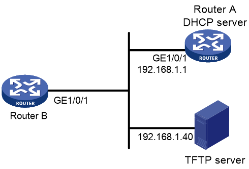
As shown in Figure 2, Router B does not have a configuration file.
Configure the servers so Router B can obtain a configuration file to complete the following configuration tasks:
· Enable the administrator to Telnet to Router B to manage Router B.
· Require the administrator to enter the correct username and password at login.
Procedure
1. Configure the DHCP server:
# Enable DHCP.
<RouterA> system-view
[RouterA] dhcp enable
# Configure address pool 1 to assign IP addresses on the 192.168.1.0/24 subnet to clients. Specify the TFTP server and configuration file name for the clients.
[RouterA] dhcp server ip-pool 1
[RouterA-dhcp-pool-1] network 192.168.1.0 24
[RouterA-dhcp-pool-1] tftp-server ip-address 192.168.1.40
[RouterA-dhcp-pool-1] bootfile-name device.cfg
[RouterA-dhcp-pool-market] quit
2. Configure the TFTP server:
# On the TFTP server, create a configuration file named device.cfg.
#
telnet server enable
#
local-user user
password simple abcabc
service-type telnet
quit
#
user-interface vty 0 63
authentication-mode scheme
user-role network-admin
quit
#
interface gigabitethernet 1/0/1
port link-mode route
ip address dhcp-alloc
return
# Start TFTP service software. (Details not shown.)
Verifying the configuration
1. Power on Router B.
2. After Router B starts up, display assigned IP addresses on Router A.
<RouterA> display dhcp server ip-in-use
IP address Client identifier/ Lease expiration Type
Hardware address
192.168.1.2 0030-3030-632e-3239- Dec 12 17:41:15 2013 Auto(C)
3035-2e36-3736-622d-
4574-6830-2f30-2f32
3. Telnet to 192.168.1.2 from Router A.
<RouterA> telnet 192.168.1.2
4. Enter username user and password abcabc as prompted. (Details not shown.)
You are logged in to Router B.
Example: Using an HTTP server and Tcl scripts for automatic configuration
Network configuration
As shown in Figure 3, Router B does not have a configuration file.
Configure the servers so Router B can obtain a Tcl script to complete the following configuration tasks:
· Enable the administrator to Telnet to Router B to manage Router B.
· Require the administrator to enter the correct username and password at login.

Procedure
1. Configure the DHCP server:
# Enable DHCP.
<RouterA> system-view
[RouterA] dhcp enable
# Configure address pool 1 to assign IP addresses on the 192.168.1.0/24 subnet to clients.
[RouterA] dhcp server ip-pool 1
[RouterA-dhcp-pool-1] network 192.168.1.0 24
# Specify the URL of the script file for the clients.
[RouterA-dhcp-pool-1] bootfile-name http://192.168.1.40/device.tcl
2. Configure the HTTP server:
# Create a configuration file named device.tcl on the HTTP server.
return
system-view
telnet server enable
local-user user
password simple abcabc
service-type telnet
quit
user-interface vty 0 63
authentication-mode scheme
user-role network-admin
quit
interface gigabitethernet 1/0/1
port link-mode route
ip address dhcp-alloc
return
# Start HTTP service software and enable HTTP service. (Details not shown.)
Verifying the configuration
1. Power on Router B.
2. After Router B starts up, display assigned IP addresses on Router A.
<RouterA> display dhcp server ip-in-use
IP address Client identifier/ Lease expiration Type
Hardware address
192.168.1.2 0030-3030-632e-3239- Dec 12 17:41:15 2013 Auto(C)
3035-2e36-3736-622d-
4574-6830-2f30-2f32
3. Telnet to 192.168.1.2 from Router A.
<RouterA> telnet 192.168.1.2
4. Enter username user and password abcabc as prompted. (Details not shown.)
You are logged in to Router B.
Example: Using an HTTP server and Python scripts for automatic configuration
Network configuration
As shown in Figure 4, Router B does not have a configuration file.
Configure the servers so Router B can obtain a Python script to complete the following configuration tasks:
· Enable the administrator to Telnet to Router B to manage Router B.
· Require the administrator to enter the correct username and password at login.

Procedure
1. Configure the DHCP server:
# Enable DHCP.
<RouterA> system-view
[RouterA] dhcp enable
# Configure address pool 1 to assign IP addresses on the 192.168.1.0/24 subnet to clients.
[RouterA] dhcp server ip-pool 1
[RouterA-dhcp-pool-1] network 192.168.1.0 24
# Specify the URL of the script file for the clients.
[RouterA-dhcp-pool-1] bootfile-name http://192.168.1.40/device.py
2. Configure the HTTP server:
# Create a configuration file named device.py on the HTTP server.
#!usr/bin/python
import comware
comware.CLI(‘system-view ;telnet server enable ;local-user user ;password simple abcabc ;service-type telnet ;quit ;user-interface vty 0 63 ;authentication-mode scheme ;user-role network-admin ;quit ;interface gigabitethernet 1/0/1 ;port link-mode route ;ip address dhcp-alloc ;return’)
# Start HTTP service software and enable HTTP service. (Details not shown.)
Verifying the configuration
1. Power on Router B.
2. After Router B starts up, display assigned IP addresses on Router A.
<RouterA> display dhcp server ip-in-use
IP address Client identifier/ Lease expiration Type
Hardware address
192.168.1.2 0030-3030-632e-3239- Dec 12 17:41:15 2013 Auto(C)
3035-2e36-3736-622d-
4574-6830-2f30-2f32
3. Telnet to 192.168.1.2 from Router A.
<RouterA> telnet 192.168.1.2
4. Enter username user and password abcabc as prompted. (Details not shown.)
You are logged in to Router B.
Example: Setting up an IRF fabric
Network configuration
As shown in Figure 5, Router A and Router B do not have a configuration file.
Configure the servers so the routers can obtain a Python script to complete their respective configurations and form an IRF fabric.
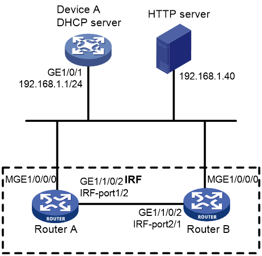
Procedure
1. Assign IP addresses to the interfaces. Make sure the devices can reach each other. (Details not shown.)
2. Configure the following files on the HTTP server:
|
File |
Content |
Remarks |
|
.cfg configuration file |
Commands required for IRF setup. |
You can create a configuration file by copying and modifying the configuration file of an existing IRF fabric. |
|
sn.txt |
Serial numbers of the member routers. |
Each SN uniquely identifies a router. These SNs will be used for assigning a unique IRF member ID to each member router. |
|
(Optional.) .ipe or .bin software image file |
Software images. |
If the member routers are running different software versions, you must prepare the software image file used for software upgrade. |
|
.py Python script file |
Python commands that complete the following tasks: a (Optional.) Verify that the flash memory has sufficient space for the files to be downloaded. b Download the configuration file and sn.txt. c (Optional.) Download the software image file and specify it as the main startup image file. d Resolve sn.txt and assign a unique IRF member ID to each SN. e Specify the configuration file as the main next-startup configuration file. f Reboot the member routers. |
For more information about Python script configuration, see "Using Python." |
3. Configure Device A as the DHCP server:
# Enable DHCP.
<DeviceA> system-view
[DeviceA] dhcp enable
# Configure address pool 1 to assign IP addresses on the 192.168.1.0/24 subnet to clients.
[DeviceA] dhcp server ip-pool 1
[DeviceA-dhcp-pool-1] network 192.168.1.0 24
# Specify the URL of the script file for the clients.
[DeviceA-dhcp-pool-1] bootfile-name http://192.168.1.40/device.py
[DeviceA-dhcp-pool-1] quit
# Enable the DHCP server on GigabitEthernet 1/0/1.
[DeviceA] interface gigabitethernet 1/0/1
[DeviceA-GigabitEthernet1/0/1] dhcp select server
[DeviceA-GigabitEthernet1/0/1] quit
4. Power on Router A and Router B.
Router A and Router B will obtain the Python script file from the DHCP server and execute the script. After completing the IRF configuration, Router A and Router B reboot.
5. After Router A and Router B start up again, use a cable to connect Router A and Router B through their IRF physical ports.
Router A and Router B will elect a master member. The subordinate member will reboot to join the IRF fabric.
Verifying the configuration
# On Router A, display IRF member devices. You can also use the display irf command on Router B to display IRF member devices.
<RouterA> display irf
MemberID Role Priority CPU-Mac Description
1 Standby 1 00e0-fc0f-8c02 ---
*+2 Master 30 00e0-fc0f-8c14 ---
--------------------------------------------------
* indicates the device is the master.
+ indicates the device through which the user logs in.
The Bridge MAC of the IRF is: 000c-1000-1111
Auto upgrade : yes
Mac persistent : always
Domain ID : 0
Auto merge : yes
The output shows that the routers have formed an IRF fabric.
