- Table of Contents
- Related Documents
-
| Title | Size | Download |
|---|---|---|
| 01-Hardware Information and Specifications | 2.43 MB |
1 Product models and technical specifications
Product models
This document is applicable to the S9820-8M switch model (BOM part number 0235A2SM, product code LS-9820-8M).
Technical specifications
Table1-1 Technical specifications
|
Item |
Specification |
|
Dimensions (H × W × D) |
130.5 × 440 × 760 mm (5.14 × 17.32 × 29.92 in) |
|
Weight (fully configured with fan trays and power supplies, excluding transceiver modules and cables) |
≤ 45 kg (99.21 lb) |
|
Console port |
· 1 × mini USB console port · 1 × serial console port |
|
Management Ethernet port |
· 1 × 10/100/1000BASE-T copper port · 1 × SFP port |
|
USB port |
1 |
|
Power supply slot |
4 |
|
Interface module slot |
8 |
|
Fan tray slot |
5 |
|
Minimum power consumption |
305 W For the conditions under which the minimum power consumption is collected, see Table1-2. |
|
Typical power consumption |
· Configured with LSWM116H interface modules: 921 W · Configured with LSWM1M4CD interface modules: 820.2 W For the conditions under which the typical power consumption is collected, see Table1-2. |
|
Maximum power consumption |
· Configured with LSWM116H interface modules: 1818 W · Configured with LSWM1M4CD interface modules: 1654.8 W For the conditions under which the maximum power consumption is collected, see Table1-2. |
|
Chassis leakage current compliance |
· UL60950-1 · EN60950-1 · IEC60950-1 · GB4943.1 |
|
Operating temperature |
0°C to 45°C (32°F to 113°F) |
|
Operating humidity |
5% RH to 95% RH, noncondensing |
|
Fire resistance compliance |
· UL60950-1 · EN60950-1 · IEC60950-1 · GB4943.1 |
Table1-2 Power consumption collection conditions
|
Item |
Minimum power consumption |
Typical power consumption |
Maximum power consumption |
|
Configuration |
· Two power supplies · No transceiver modules or cables installed in ports |
· Two power supplies · Fully configured with cables |
· Two power supplies · Fully configured with transceiver modules |
|
Load |
No |
50% load |
100% load |
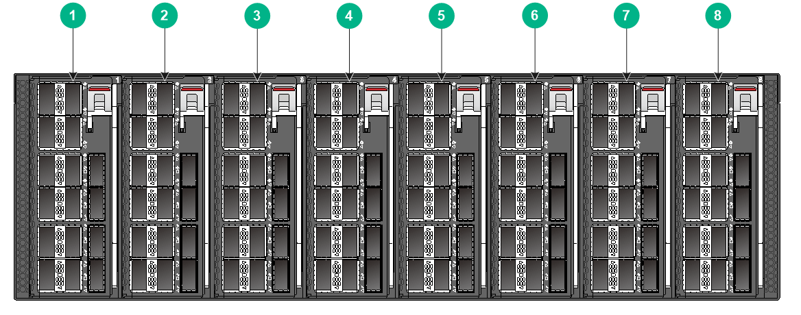
2 Chassis views
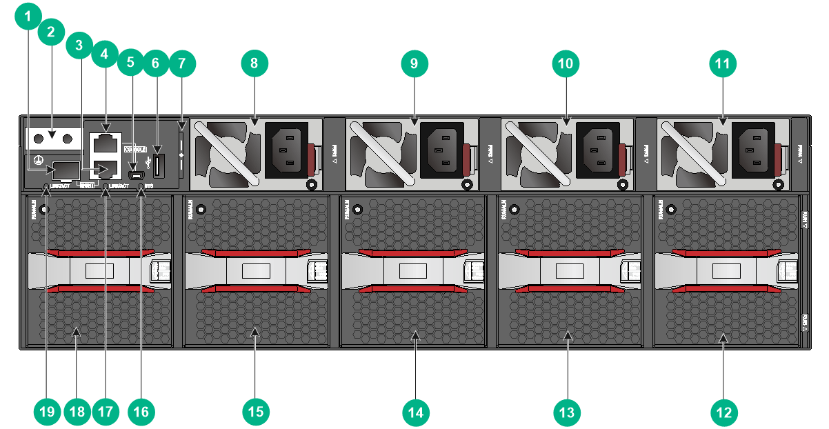
|
(1) Interface module 1 |
(2) Interface module 2 |
|
(3) Interface module 3 |
(4) Interface module 4 |
|
(5) Interface module 5 |
(6) Interface module 6 |
|
(7) Interface module 7 |
(8) Interface module 8 |
|
(1) Fiber management Ethernet port |
(2) Grounding point |
|
(3) Copper management Ethernet port |
(4) Serial console port |
|
(5) Mini USB console port |
(6) USB port |
|
(7) Serial label pull tab |
(8) Power supply 1 |
|
(9) Power supply 2 |
(10) Power supply 3 |
|
(11) Power supply 4 |
(12) Fan tray 5 |
|
(13) Fan tray 4 |
(14) Fan tray 3 |
|
(15) Fan tray 2 |
(16) System status LED (SYS) |
|
(17) Copper management Ethernet port LED (LINK/ACT) |
|
|
(18) Fan tray 1 |
(19) Fiber management Ethernet port LED (LINK/ACT) |
The ESN serial number and MAC address of the switch can be found on the serial label pull tab.
The switch comes with power supply slots PWR1 and PWR2 empty and power supply slots PWR3 and PWR4 each installed with a filler panel. You can install two to four power supplies for the switch as needed. In Figure2-2, PSR1600B-12A-B power supplies are installed in the four power supply slots.
The switch comes with the five fan tray slots empty. You must install five fan trays of the same model for the switch. In Figure2-2, FAN-80B-1-B fan trays are installed in the five fan tray slots.
The switch comes with the eight interface module slots each installed with a filler panel. You can install one to eight interface modules for the switch as needed. In Figure2-1, LSWM116H interface modules are installed in the eight interface module slots.
3 Removable components
The switch uses modular design and supports the following removable components:
· PSR1600B-12A-B power supply (BOM part number: 0231ABV7)
· FAN-80B-1-B fan tray (BOM part number: 0231ABV6)
· LSWM116H interface module (BOM part number: 0231ABV8)
· LSWM1M4CD interface module (BOM part number: 0231ACXF)
|
|
IMPORTANT: For interface module compatibility with software releases, see the release notes. |
Power supplies
|
|
WARNING! When the switch has power supplies in redundancy, you can replace a power supply without powering off the switch. To avoid device damage and personal injury, make sure the power supply is powered off before you replace it. |
The switch can operate correctly with two power supplies. You can install three or four power supplies on the switch for 2+1 or 2+2 redundancy, respectively.
Table3-1 Power supply specifications
|
Power supply model |
Specifications |
Remarks |
|
PSR1600B-12A-B |
· Rated input voltage: 100 VAC to 240 VAC @ 50 Hz or 60 Hz · Max input voltage: 90 VAC to 290 VAC @ 47 Hz to 63 Hz · Max output power: 1600 W · Melting current of the power supply fuse: 10 A/250 V |
For more information about the power supply, see H3C PSR1600B-12A-B Power Module User Manual. |
Fan trays
|
|
CAUTION: For adequate heat dissipation, you must install five fan trays of the same model for the switch. |
Table3-2 Fan tray specifications
|
Fan tray model |
Item |
Specifications |
|
FAN-80B-1-B |
Dimensions (including the handle) |
84 × 81 × 240 mm (3.31 × 3.19 × 9.45 in) |
|
Fan speed |
12800 R.P.M |
|
|
Maximum airflow |
130 CFM |
|
|
Maximum power consumption |
102 W |
|
|
Documentation reference |
H3C FAN-80B-1-B Fan tray User Guide |
Interface modules
The switch provides eight interface module slots. Table3-3 describes the interface modules available for the switch.
Table3-3 Interface module specifications
|
Model |
Description |
Port type and number |
Available transceiver modules and cables |
|
LSWM116H |
16-port QSFP28 Ethernet optical interface module |
16 × QSFP28 ports |
See "QSFP28 port." |
|
LSWM1M4CD |
4-port 400GBASE Ethernet optical interface module(QSFP-DD) |
4 × QSFP-DD ports |
See "QSFP-DD port." |
4 Ports and LEDs
As a best practice, use H3C transceiver modules and cables for the switch. H3C transceiver modules and cables are subject to change over time. For the most up-to-date list of H3C transceiver modules and cables, contact H3C Support or marketing staff.
For information about the specifications of H3C transceiver modules and cables, see H3C Transceiver Modules User Guide.
The switch uses high-power ports in high density. Bringing up the ports simultaneously takes a comparatively long time. To reduce the time to bring up a port, the system does not turn off the laser transmitter on the transceiver module when shutting down the port.
Ports
Console port
The switch has a serial console port and a mini USB console port.
Table4-1 Console port specifications
|
Item |
Serial console port |
Mini USB console port |
|
Connector type |
RJ-45 |
USB mini-Type B |
|
Compliant standard |
EIA/TIA-232 |
USB 2.0 |
|
Transmission baud rate |
9600 bps (default) to 115200 bps |
|
|
Services |
· Provides connection to an ASCII terminal. · Provides connection to the serial port of a local terminal (a PC for example) or remote terminal (through a pair of modems) running a terminal emulation program. |
· Provides connection to an ASCII terminal. · Provides connection to the USB port of a local terminal (a PC for example) running a terminal emulation program. |
Management Ethernet port
The switch has two management Ethernet ports: a copper management port and an SFP management port. You can connect the ports to a local PC for software loading and debugging or to a remote management station for remote management.
Table4-2 Management Ethernet port specifications
|
Item |
Specification |
|
Connector type |
· 10/100/1000BASE-T management port: RJ-45. · SFP management port: LC. |
|
Port transmission rate, duplex mode, and auto MDI/MDI-X |
· 10/100/1000BASE-T management port: ¡ 10/100 Mbps, half/full duplex, auto MDI/MDI-X. ¡ 1000 Mbps, full duplex, auto MDI/MDI-X. · SFP management port: 1000/100 Mbps, full duplex. |
|
Transmission medium and max transmission distance |
· 10/100/1000BASE-T management port: 100 m (328.08 ft) over category-5 UTP cable. · SFP management port: See FE SFP transceiver modules in Table4-3 and GE SFP transceiver modules in Table4-4. |
|
Functions and services |
Software upgrade and network management. |
Table4-3 FE SFP transceiver modules available for the SFP management port
|
FE SFP transceiver module |
Central wavelength (nm) |
Connector |
Fiber type and diameter (µm) |
Max transmission distance |
|
SFP-FE-SX-MM1310-A |
1310 |
LC |
Multi-mode, 50/125 |
2 km (1.24 miles) |
|
Multi-mode, 62.5/125 |
||||
|
SFP-FE-LX-SM1310-A |
1310 |
LC |
Single-mode, 9/125 |
15 km (9.32 miles) |
|
SFP-FE-LH40-SM1310 |
1310 |
LC |
Single-mode, 9/125 |
40 km (24.86 miles) |
Table4-4 GE SFP transceiver modules available for the SFP management port
|
GE SFP transceiver module |
Central wavelength (nm) |
Connector |
Cable/Fiber type and diameter (µm) |
Modal bandwidth (MHz × km) |
Max transmission distance |
|
SFP-GE-T |
N/A |
RJ-45 |
Twisted pair cable |
N/A |
100 m (328.08 ft) |
|
SFP-GE-SX-MM850-A |
850 |
LC |
Multi-mode, 50/125 |
500 |
550 m (1804.46 ft) |
|
400 |
500 m (1640.42 ft) |
||||
|
Multi-mode, 62.5/125 |
200 |
275 m (902.23 ft) |
|||
|
160 |
200 m (656.17 ft) |
||||
|
SFP-GE-LX-SM1310-A |
1310 |
LC |
Single-mode, 9/125 |
N/A |
10 km (6.21 miles) |
|
Multi-mode, 50/125 |
500 or 400 |
550 m (1804.46 ft) |
|||
|
Multi-mode, 62.5/125 |
500 |
550 m (1804.46 ft) |
|||
|
SFP-GE-LH40-SM1310 |
1310 |
LC |
Single-mode, 9/125 |
N/A |
40 km (24.86 miles) |
|
SFP-GE-LH40-SM1550 |
1550 |
LC |
Single-mode, 9/125 |
N/A |
40 km (24.86 miles) |
|
SFP-GE-LH80-SM1550 |
1550 |
LC |
Single-mode, 9/125 |
N/A |
80 km (49.71 miles) |
USB port
The switch has one OHCI-compliant USB 2.0 port that can upload and download data at a rate up to 480 Mbps. You can use this USB port to access the file system on the flash of the switch, for example, to upload or download application and configuration files.
The USB port supplies power as per USB 2.0 specifications. Use only USB 2.0-compliant USB devices for the USB port. The port might not identify USB devices that are not compliant with USB 2.0.
|
|
NOTE: USB devices from different vendors vary in compatibilities and drivers. H3C does not guarantee correct operation of USB devices of all vendors on the switch. If a USB device fails to operate on the switch, replace it with one from another vendor. |
QSFP28 port
The LSWM116H interface module provides 16 QSFP28 ports and does not support splitting a QSFP28 port into four breakout interfaces.
The following transceiver modules and cables are available for the QSFP28 ports:
· QSFP28 transceiver modules in Table4-5.
· QSFP28 copper cables in Table4-6.
· QSFP28 fiber cables in Table4-7.
Table4-5 QSFP28 transceiver modules available for the QSFP28 ports
|
QSFP28 transceiver module |
Central wavelength (nm) |
Connector |
Fiber type and diameter (µm) |
Modal bandwidth (MHz*km) |
Maximum transmission distance |
|
QSFP-100G-SR4-MM850 |
850 |
MPO (PC polished, 12-fiber) |
Multi-mode, 50/125 |
2000 |
70 m (229.66 ft) |
|
4700 |
100 m (328.08 ft) |
||||
|
QSFP-100G-PSM4-SM1310 |
1295 to 1325 |
MPO (APC polished, 12-fiber) |
Single-mode, 9/125 |
N/A |
0.5 km (0.31 miles) |
|
QSFP-100G-LR4-WDM1300 |
Four lanes: · 1295 · 1300 · 1304 · 1309 |
LC |
Single-mode, 9/125 |
N/A |
10 km (6.21 miles) |
|
QSFP-100G-LR4L-WDM1300 |
Four lanes: · 1264.5 to 1277.5 · 1284.5 to 1297.5 · 1304.5 to 1317.5 · 1324.5 to 1337.5 |
LC |
Single-mode, 9/125 |
N/A |
2 km (1.24 miles) |
Table4-6 QSFP28 copper cables available for the QSFP28 ports
|
QSFP28 copper cable |
Cable length |
|
QSFP-100G-D-CAB-1M |
1 m (3.28 ft) |
|
QSFP-100G-D-CAB-3M |
3 m (9.84 ft) |
|
QSFP-100G-D-CAB-5M |
5 m (16.40 ft) |
Table4-7 QSFP28 fiber cables available for the QSFP28 ports
|
QSFP28 fiber cable |
Cable length |
|
QSFP-100G-D-AOC-7M |
7 m (22.97 ft) |
|
QSFP-100G-D-AOC-10M |
10 m (32.81 ft) |
|
QSFP-100G-D-AOC-20M |
20 m (65.62 ft) |
|
|
NOTE: MPO connectors include physical contact (PC) connectors with a flat-polished face and angle-polished contact (APC) connectors with an angle-polished face (8°). |
QSFP-DD port
The LSWM1M4CD interface module provides 4 QSFP-DD ports.
The following transceiver modules and cables are available for the QSFP-DD ports:
· QSFP-DD transceiver modules in Table4-8.
· QSFP-DD copper cables in Table4-9.
Table4-8 QSFP-DD transceiver modules available for the QSFP-DD ports
|
QSFP-DD transceiver module |
Central wavelength (nm) |
Connector |
Fiber type and diameter (µm) |
Modal bandwidth (MHz*km) |
Maximum transmission distance |
|
QSFPDD-400G-SR8-MM850 |
850 |
MPO (APC polished, 16-fiber) |
50/125 µm MMF |
2000 |
70 m (229.66 ft) |
|
4700 |
100 m (328.08 ft) |
||||
|
QSFPDD-400G-FR4-WDM1300 |
Four lanes · 1271 · 1291 · 1311 · 1331 |
LC |
Single-mode, 9/125 |
N/A |
2 km (1.24 miles) |
Table4-9 QSFP-DD copper cables available for the QSFP-DD ports
|
QSFP-DD copper cable |
Cable length |
|
QSFPDD-400G-D-CAB-2M |
2 m (6.56 ft) |
LEDs
System status LED
The system status LED shows the operating status of the switch.
Table4-10 System status LED description
|
LED mark |
Status |
Description |
|
SYS |
Steady green |
The switch is operating correctly. |
|
Flashing green |
The switch is performing power-on self-test (POST). |
|
|
Steady red |
The system has failed to pass POST or a fault has occurred. |
|
|
Flashing blue (3 Hz) |
Helps identifying the switch. To identify the switch location, execute the locator blink blink-time command. This LED will flash blue at 3 Hz. |
|
|
Off |
The switch is powered off or has failed to start up. |
QSFP28 port LED
Table4-11 QSFP28 port LED description
|
LED status |
Description |
|
Steady green |
A transceiver module or cable has been correctly installed in the port. The port has a link and is operating at 100 Gbps. |
|
Flashing green |
The port is sending or receiving data at 100 Gbps. |
|
Off |
No transceiver module or cable has been installed in the port, or no link is present on the port. |
QSFP-DD port LED
Table4-12 QSFP-DD port LED description
|
LED status |
Description |
|
Steady green |
A transceiver module is installed in the port. The port is operating at its maximum speed of 400 Gbps, and a link is present on the port. |
|
Flashing green |
The port is sending or receiving data at its maximum speed of 400 Gbps. |
|
Steady yellow |
A transceiver module is installed in the port. The port is operating at a speed lower than the maximum speed. |
|
Flashing yellow (3 Hz) |
The port is sending or receiving data at a speed lower than the maximum speed. |
|
Off |
No transceiver module is installed in the port, or no link is present on the port. |
Management Ethernet port LEDs
The switch provides a LINK/ACT LED for each management Ethernet port to indicate their operating status.
Table4-13 Management Ethernet port LED description
|
LED mark |
Status |
Description |
|
LINK/ACT |
Off |
No link is present on the port. |
|
Steady green |
The port is operating at 1000 Mbps. |
|
|
Flashing green |
The port is receiving or sending data at 1000 Mbps. |
|
|
Steady yellow |
The port is operating at 100 Mbps. |
|
|
Flashing yellow |
The port is receiving or sending data at 100 Mbps. |
Power supply alarm LED
A PSR1600B-12A-B power supply provides an alarm LED.
Table4-14 Description for the alarm LED on a PSR1600B-12A-B power supply
|
Status |
Description |
|
Steady green |
The power supply is operating correctly and in active state. |
|
Flashing green at 1 Hz |
The power supply is operating correctly and in standby state. |
|
Flashing green at 2 Hz |
The power supply software is being upgraded. |
|
Steady amber |
The power supply is faulty or has entered self-protection mode. |
|
Flashing amber at 1 Hz |
An alarm has occurred on the power supply. |
|
Flashing amber at 2 Hz |
The power supply does not have input power but the power supplies working in parallel with it have input power. |
|
Off |
Neither this power supply nor power supplies working in parallel with it have input power. |
Fan tray alarm LED
A FAN-80B-1-B fan tray provides an alarm LED.
Table4-15 Description for the alarm LED on a FAN-80B-1-B fan tray
|
Status |
Description |
|
Steady green |
The fan tray is operating correctly. |
|
Steady red |
The fan tray is faulty. |
|
Off |
The fan tray is operating correctly or no power is present. |
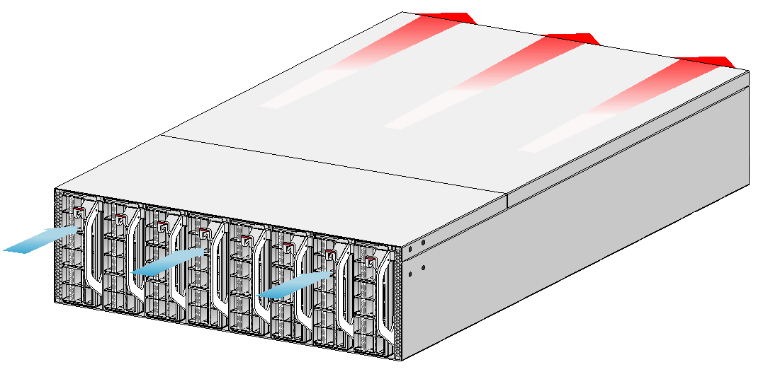
5 Cooling system
|
|
CAUTION: The chassis and power supplies use separate air aisles. Make sure the two aisles are not blocked when the switch is operating. |
The switch uses a highly efficient front-rear air aisle cooling system to ensure adequate heat dissipation and improve system reliability. Consider the ventilation design at the installation site when you plan the installation location for the switch.
Table5-1 Fan tray options for the switch
|
Available fan tray |
Airflow direction of the chassis |
|
FAN-80B-1-B |
From the port side to the power supply side |
Figure5-1 Airflow from the port side to the power supply side (with FAN-80B-1-B fan trays)
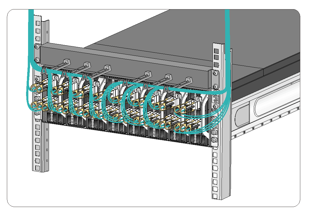
6 Cable routing recommendations
You can purchase one cable management frame for the switch and install it on the rack posts immediately above or below the switch as required. For more organized cabling, you can purchase two cable management frames so that the switch has a cable management frame installed both above and below it.
Route the signal cables along the left or right side of the cable management frame as required. Cable routing in Figure6-1 is for your reference.