- Table of Contents
- Related Documents
-
| Title | Size | Download |
|---|---|---|
| 04-EVPN VPWS configuration | 517.23 KB |
Contents
Remote connection establishment
Inter-AS communication of EVPN VPWS
Restrictions and guidelines: MDC restrictions
Configuring a remote connection
Configuring an Ethernet service instance on an interface
Configuring EVPN route advertisement
Restrictions and guidelines for EVPN route advertisement configuration
Enabling BGP to advertise BGP EVPN routes
Configuring optimal route selection and route advertisement settings
Mapping an AC to a cross-connect
About mapping an AC to a cross-connect
Restrictions and guidelines for mapping an AC to a cross-connect
Mapping an Ethernet service instance to a cross-connect
Enabling packet statistics for an AC
Restrictions and guidelines for AC packet statistics
Enabling packet statistics for an Ethernet service instance
Display and maintenance commands for EVPN VPWS
EVPN VPWS configuration examples
Example: Configuring a remote connection between singlehomed sites
Example: Configuring PW concatenation
Example: Configuring inter-AS option A
Example: Configuring inter-AS option B
Example: Configuring inter-AS option C
Configuring EVPN VPWS
About EVPN VPWS
EVPN Virtual Private Wire Service (VPWS) is a Layer 2 VPN technology that uses MP-BGP for BGP EVPN route advertisement in the control plane and MPLS for forwarding in the data plane. EVPN VPWS provides point-to-point forwarding services for users by using ACs and PWs associated with cross-connects without MAC address table lookup.
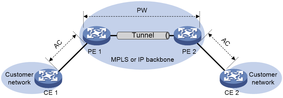
EVPN VPWS network model
As shown in Figure 1, an EVPN VPWS network contains the following devices:
· Customer edge (CE)—Customer device directly connected to the service provider network.
· Provider edge (PE)—Service provider device connected to CEs. PEs provide access to the EVPN VPWS network and forward traffic between customer network sites by using public tunnels.
A PE uses ACs, PWs, tunnels, and cross-connects to provide EVPN VPWS services.
· Attachment circuit (AC)—A physical or virtual link between a CE and a PE.
· Pseudowire (PW)—A virtual bidirectional connection between two PEs. A PW comprises a pair of LSPs in opposite directions.
· Public tunnel—A connection that carries one or more PWs across the MPLS or IP backbone. A public tunnel can be an LSP, GRE tunnel, or MPLS TE tunnel.
· Cross-connect—A connection formed by two physical or virtual circuits such as ACs and PWs. It switches packets between the two physical or virtual circuits. Cross-connects include AC to AC cross-connect and AC to PW cross-connect.
Remote connection establishment
To set up a remote EVPN VPWS connection:
1. Set up a public tunnel to carry one or more PWs between PEs.
2. Set up a PW to connect customer networks.
3. Set up an AC between a PE and a CE.
4. Bind the AC to the PW.
After the PE receives packets from the AC, it adds the PW label into the packets and sends the packets to the peer PE through the public tunnel.
After the peer PE receives the packets from the public tunnel, it removes the PW label of the packets and forwards the packets to the AC bound to the PW.
Public tunnel establishment
The public tunnel can be an LSP, MPLS TE, or GRE tunnel.
If multiple public tunnels are set up between two PEs, you can configure a tunnel policy to control tunnel selection. For more information about tunnel policies, see MPLS Configuration Guide.
If a PW is established over an LSP or MPLS TE tunnel, packets on the PW have two labels. The outer label is the public LSP or MPLS TE tunnel label that MPLS uses to forward the packet to the peer PE. The inner label is the PW label that the peer PE uses to forward the packet to the destination CE.
PW establishment
A PW is established between two PEs based on the local and remote service IDs configured on the PEs. In an EVPN VPWS network, each PE advertises its local service ID through Ethernet auto-discovery routes and compares received local service IDs with its remote service ID. A PE establishes a unidirectional LSP to a peer If the local service ID advertised by the peer matches the remote service ID. PW establishment is finished when two LSPs in opposite directions are established between two PEs.
AC establishment
For EVPN VPWS, an AC is associated with a cross-connect and can be a Layer 3 Ethernet interface, Layer 3 Ethernet subinterface, or Ethernet service instance on a PE. An Ethernet service instance is created on a Layer 2 Ethernet interface to match incoming customer traffic on that interface based on a frame match criterion.
AC-to-PW bindings
For PEs to forward packets between an AC and a PW, bind the AC to the PW.
Control word
The control word field is between the MPLS label stack and the Layer 2 data. It carries control information for the Layer 2 frame, for example, the sequence number.
The control word feature has the following functions:
· Avoids fragment disorder. In multipath forwarding, fragments received might be disordered. The control word feature reorders the fragments according to the sequence number carried in the control word field.
· Identifies the original payload length for packets that include padding.
The control word field is optional for EVPN PWs. You can configure whether to carry the control word field in packets sent on the PW. If you enable the control word feature on both PEs, packets transmitted on the PW carry the control word field. Otherwise, the packets do not carry the control word field.
L2VPN flow label
Packets carrying different types of traffic might be transmitted through the same PW and encapsulated with the same PW label. The P devices forward the traffic flows of a PW over the same path even if Equal Cost Multiple Paths (ECMPs) exist.
The L2VPN flow label feature can enable a P device to perform load sharing on packets based on the flow types.
After you configure this feature, the P and PE devices process packets as follows:
· When the ingress PE encapsulates a packet, it adds a flow label before it adds a PW label, as shown in Figure 2.
The ingress PE adds different flow labels for packets of different traffic types.
· The P devices perform load sharing on packets based on the flow labels.
· The egress PE removes both the PW and flow labels from a packet before forwarding the packet.
Figure 2 L2VPN flow label feature
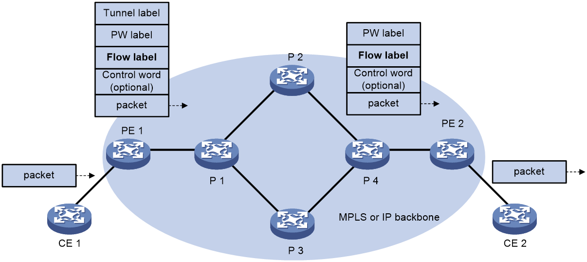
You can enable the flow label sending, receiving, or both sending and receiving capabilities on a PE.
· The sending capability enables a PE to send packets with flow labels. The PE adds a flow label before it adds a PW label to a packet during PW encapsulation.
· The receiving capability enables a PE to identify the flow label in a received packet and removes the flow label before forwarding the packet.
For two PEs to successfully negotiate the flow label capabilities, make sure one end has the sending capability and the other end has the receiving capability.
For EVPN VPWS PWs, you must manually configure flow label capabilities for the local and remote PEs.
PW concatenation
About PW concatenation
As shown in Figure 3, EVPN VPWS supports concatenating two or more PWs into one PW. PW concatenation allows two PEs that do not have an end-to-end public tunnel between them to communicate. An intermediate PE forwards packets between two concatenated PWs as follows:
1. Removes the tunnel identifier and PW label from the packets received on one PW.
2. Encapsulates the packets with the label of another PW and forwards them through the public tunnel that conveys this PW.
Two PWs are concatenated by creating them on the same cross-connect. For example, to concatenate PW 1 and PW 2 in Figure 3, create them on the same cross-connect on PE 2.
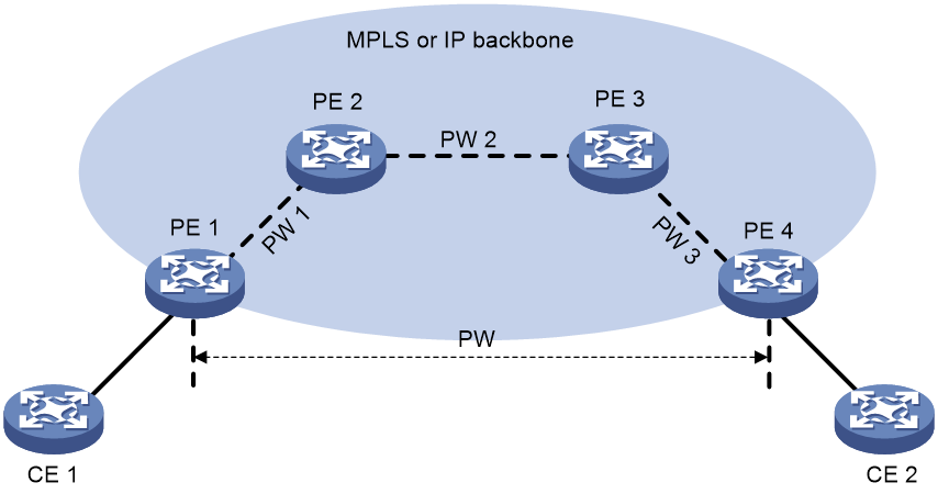
PW concatenation includes intra-AS PW concatenation and inter-AS PW concatenation.
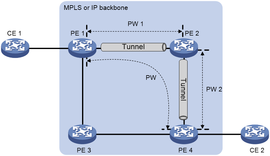
· Intra-AS PW concatenation—Concatenates PWs within an AS. As shown in Figure 4, all PEs are in the same AS, and no end-to-end public tunnel exists between PE 1 and PE 4. By concatenating PW 1 and PW 2, you can enable PE 1 and PE 4 to communicate through the existing public tunnels instead of creating a new one.
Figure 4 Intra-AS PW concatenation
· Inter-AS PW concatenation—Concatenates PWs in different ASs. For more information, see "Inter-AS option B."
Inter-AS communication of EVPN VPWS
In an inter-AS networking scenario, multiple sites of an EVPN VPWS network are connected to multiple ISPs in different ASs, or to multiple ASs of an ISP.
EVPN VPWS provides the following inter-AS communication solutions:
· Inter-AS option A—Associates the AC between ASBRs with each EVPN PW established between a PE and ASBR pair.
· Inter-AS option B—Establishes an EVPN PW between ASBRs and concatenates it with the EVPN PWs established between PE and ASBR pairs.
· Inter-AS option C—Establishes an EVPN PW between PEs in different ASs through a multihop MP-EGBP session.
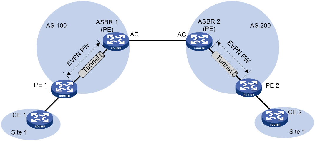
Inter-AS option A
As shown in Figure 5, in this solution, PEs of two ASs are directly connected, and each PE is also the ASBR of its AS. Each PE treats the other as a CE and associates its EVPN PW with the interface facing the peer PE for inter-AS communication.
This solution features simple implementation. You need to configure only EVPN PW and AC associations for each site on the PEs that act as ASBRs. However, the management workload increases if more sites are attached to the ASBRs.
Figure 5 Inter-AS option A network model
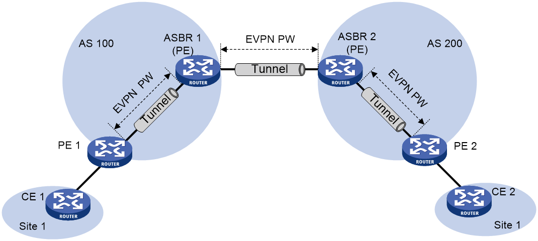
Inter-AS option B
As shown in Figure 6, in this solution, an EVPN PW is established between the ASBRs for inter-AS communication. The ASBRs uses MP-EBGP to exchange BGP EVPN routes to establish the EVPN PW. The PE and the ASBR in each AS use MP-IBGP to establish an EVPN PW. The EVPN PWs between the ASBRs and between each PE and ASBR pair are concatenated to forward inter-AS traffic.
This solution provides better scalability than inter-AS option A. To use this solution, you need to configure PW concatenation for each pair of sites.
Figure 6 Inter-AS option B network model
Inter-AS option C
As shown in Figure 7, in this solution, PEs in different ASs establish a multihop MP-EGBP session to exchange BGP EVPN routes and create an EVPN PW. Each PE must have a route to the peer PE and a label for the route so that the inter-AS public tunnel can be set up between the PEs. Inter-AS option C sets up a public tunnel by using the following methods:
· A label distribution protocol within the AS, for example, LDP.
· Labeled IPv4 unicast route advertisement by ASBRs through BGP.
Labeled IPv4 unicast route advertisement refers to the process of assigning MPLS labels to IPv4 unicast routes and advertising IPv4 unicast routes and their labels.
Figure 7 Inter-AS option C network model
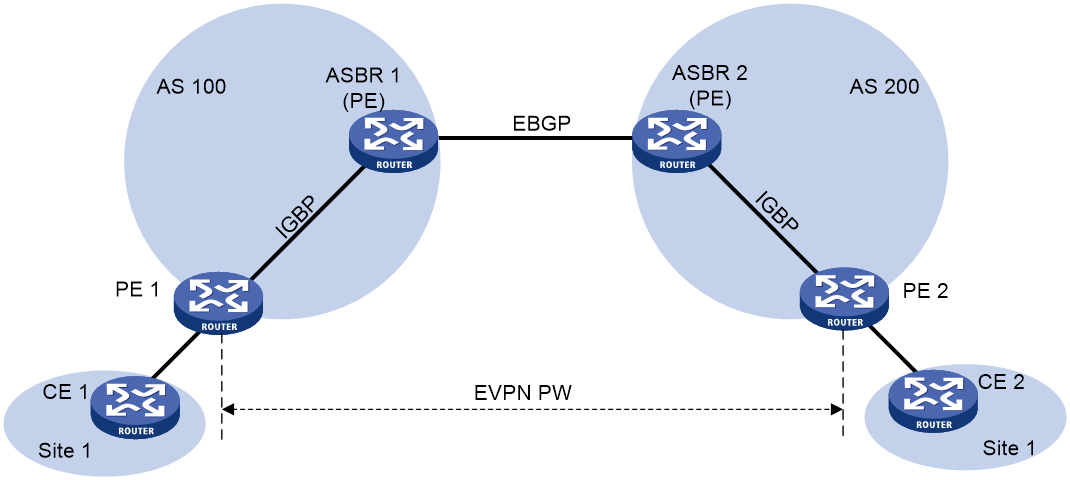
The following is the process for setting up a public tunnel between PE 1 and PE 2 in Figure 7:
1. Within AS 100, the public tunnel from ASBR 1 to PE 1 is set up by using a label distribution protocol, for example, LDP.
Assume that the outgoing label for the public tunnel on ASBR 1 is L1.
2. ASBR 1 advertises labeled IPv4 unicast routes to ASBR 2 through EBGP.
The route destined for PE 1 and the label (L2) assigned by ASBR 1 to the route are advertised from ASBR 1 to ASBR 2. The next hop of the route is ASBR 1. The public tunnel from ASBR 2 to ASBR 1 is set up. The incoming label for the public tunnel on ASBR 1 is L2.
3. ASBR 2 advertises labeled IPv4 unicast routes to PE 2 through IBGP.
The route destined for PE 1 and the label (L3) assigned by ASBR 2 to the route are advertised from ASBR 2 to PE 2. The next hop for the route is ASBR 2. The public tunnel from PE 2 to ASBR 2 is set up. The incoming label for the public tunnel on ASBR 2 is L3, and the outgoing label is L2.
4. MPLS packets cannot be forwarded directly from PE 2 to ASBR 2. Within AS 200, the public tunnel from PE 2 to ASBR 2 is required to be set up hop by hop through a label distribution protocol, for example, LDP.
Assume that the outgoing label for the public tunnel on PE 3 is Lv.
After route advertisement and public tunnel setup, PE 1 and PE 2 set up a multihop MP-EBGP session to establish an EVPN PW. You must associate the EVPN PW with an AC on PE 1 and PE 2 to enable inter-AS forwarding.
To improve scalability, you can specify a RR in each AS to exchange BGP EVPN routes with PEs in the same AS. The RR in each AS maintains all BGP EVPN routes. The RRs in two ASs establish a multihop MP-EBGP session to advertise BGP EVPN routes.
Inter-AS option C features the best scalability. It allows PEs to directly exchange BGP EVPN routes. The ASBRs do not maintain or advertise BGP EVPN routes.
Restrictions and guidelines: MDC restrictions
A non-default MDC supports a maximum of 256 cross-connects.
EVPN VPWS tasks at a glance
Configuring a remote connection
To configure a remote connection, perform the following tasks:
2. Configure an AC
¡ Configuring an Ethernet service instance on an interface
3. Configuring EVPN route advertisement
4. Configuring a cross-connect
a. (Optional.) Configuring a PW class
6. Mapping an AC to a cross-connect
7. (Optional.) Enabling packet statistics for EVPN VPWS
¡ Enabling packet statistics for an AC
Configuring PW concatenation
To configure PW concatenation, perform the following tasks:
2. Configuring a cross-connect
To concatenate two PWs, create them on the same cross-connect.
a. (Optional.) Configuring a PW class
Prerequisites for EVPN VPWS
To configure EVPN VPWS, you must perform the following tasks:
1. Configure an IGP to achieve IP connectivity within the backbone.
2. Configure basic MPLS, LDP, GRE, or MPLS TE to set up public tunnels across the backbone.
Enabling L2VPN
Prerequisites
Before you enable L2VPN, perform the following tasks:
· Configure an LSR ID for the PE by using the mpls lsr-id command.
· Enable MPLS by using the mpls enable command on the transport-facing interface of the PE.
For more information about the mpls lsr-id and mpls enable commands, see MPLS Command Reference.
Procedure
1. Enter system view.
system-view
2. Enable L2VPN.
l2vpn enable
By default, L2VPN is disabled.
Configuring an Ethernet service instance on an interface
About this task
When the PE is connected to a CE through a Layer 2 Ethernet interface or Layer 2 aggregate interface, you can configure an Ethernet service instance on the interface to match packets for the AC.
Restrictions and guidelines
You cannot repeat the encapsulation command to modify the frame match criterion of an Ethernet service instance. To change the frame match criterion, first execute the undo encapsulation command to remove the original frame match criterion.
If the frame match criterion of an Ethernet service instance is removed, the binding between the Ethernet service instance and the cross-connect is removed automatically.
For more information about the MPLS L2VPN commands used in this task, see MPLS Command Reference.
Procedure
1. Enter system view.
system-view
2. Enter interface view.
¡ Enter Layer 2 Ethernet interface view.
interface interface-type interface-number
¡ Enter Layer 2 aggregate interface view.
interface bridge-aggregation interface-number
3. Create an Ethernet service instance and enter Ethernet service instance view.
service-instance instance-id
4. Configure a frame match criterion for the Ethernet service instance.
¡ Match packets with the specified inner VLAN IDs.
encapsulation c-vid vlan-id-list
¡ Match packets with the specified outer VLAN IDs.
encapsulation s-vid vlan-id-list [ only-tagged ]
¡ Match packets with the specified outer and inner VLAN IDs.
encapsulation s-vid vlan-id c-vid { vlan-id-list | all }
encapsulation s-vid vlan-id-list c-vid vlan-id-list
¡ Match packets that have a VLAN tag or packets that do not have a VLAN tag.
encapsulation { tagged | untagged }
¡ Match packets that do not match any other Ethernet service instances on the interface.
encapsulation default
On an interface, you can configure the default criterion for only one Ethernet service instance. The Ethernet service instance matches all packets if it is the only instance on the interface.
By default, no frame match criterion is configured.
Configuring EVPN route advertisement
Restrictions and guidelines for EVPN route advertisement configuration
For more information about the BGP commands used in this task, see Layer 3—IP Routing Command Reference.
Enabling BGP to advertise BGP EVPN routes
1. Enter system view.
system-view
2. Configure a global router ID.
router id router-id
By default, no global router ID is configured.
3. Enable a BGP instance and enter BGP instance view.
bgp as-number [ instance instance-name ]
By default, BGP is disabled and no BGP instances exist.
4. Specify remote PEs as BGP peers.
peer { group-name | ipv4-address [ mask-length ] } as-number as-number
5. Create the BGP EVPN address family and enter BGP EVPN address family view.
address-family l2vpn evpn
6. Enable BGP to exchange BGP EVPN routes with a peer or peer group.
peer { group-name | ipv4-address [ mask-length ] } enable
By default, BGP does not exchange BGP EVPN routes with peers.
Configuring optimal route selection and route advertisement settings
1. Enter system view.
system-view
2. Enter BGP instance view.
bgp as-number [ instance instance-name ]
3. Enter BGP EVPN address family view.
address-family l2vpn evpn
4. Permit the local AS number to appear in routes from a peer or peer group and set the number of appearances.
peer { group-name | ipv4-address [ mask-length ] } allow-as-loop [ number ]
By default, the local AS number is not allowed in routes from peers.
5. Enable route target filtering for BGP EVPN routes.
policy vpn-target
By default, route target filtering is enabled for BGP EVPN routes.
6. (Optional.) Set the optimal route selection delay timer.
route-select delay delay-value
By default, the optimal route selection delay timer is 0 seconds, which means optimal route selection is not delayed.
7. Configure BGP route reflection settings:
a. Configure the device as an RR and specify a peer or peer group as its client.
peer { group-name | ipv4-address [ mask-length ] } reflect-client
By default, no RR or client is configured.
b. (Optional.) Enable BGP EVPN route reflection between clients.
reflect between-clients
By default, BGP EVPN route reflection between clients is enabled.
c. (Optional.) Configure the cluster ID of the RR.
reflector cluster-id { cluster-id | ipv4-address }
By default, an RR uses its own router ID as the cluster ID.
d. (Optional.) Create a reflection policy for the RR to filter reflected BGP EVPN routes.
rr-filter ext-comm-list-number
By default, an RR does not filter reflected BGP EVPN routes.
e. (Optional.) Create a reflection policy for the RR to filter reflected BGP EVPN routes.
reflect change-path-attribute
By default, an RR does not filter reflected BGP EVPN routes.
8. Configure the device to not change the next hop of routes advertised to an EBGP peer or peer group.
peer { group-name | ipv4-address [ mask-length ] } next-hop-invariable
By default, the device uses its address as the next hop of routes advertised to EBGP peers.
9. Apply a routing policy to routes received from or advertised to a peer or peer group.
peer { group-name | ipv4-address [ mask-length ] } route-policy route-policy-name { export | import }
By default, no routing policies are applied to routes received from or advertised to peers or peer groups.
10. Advertise the COMMUNITY attribute to a peer or peer group.
peer { group-name | ipv4-address [ mask-length ] } advertise-community
By default, the device does not advertise the COMMUNITY attribute to peers or peer groups.
11. Configure the BGP Additional Paths feature:
a. Configure the BGP Additional Paths capabilities.
peer { group-name | ipv4-address [ mask-length ] } additional-paths { receive | send } *
By default, no BGP Additional Paths capabilities are configured.
b. Set the maximum number of Add-Path optimal routes that can be advertised to a peer or peer group.
peer { group-name | ipv4-address [ mask-length ] } advertise additional-paths best number
By default, a maximum of one Add-Path optimal route can be advertised to a peer or peer group.
c. Set the maximum number of Add-Path optimal routes that can be advertised to all peers.
additional-paths select-best best-number
By default, a maximum of one Add-Path optimal route can be advertised to all peers.
Maintaining BGP sessions
Perform the following tasks in user view:
· Reset BGP sessions of the BGP EVPN address family.
reset bgp [ instance instance-name ] { as-number | ipv4-address [ mask-length ] | all | external | group group-name | internal } l2vpn evpn
· Soft-reset BGP sessions of the BGP EVPN address family.
refresh bgp [ instance instance-name ] { ipv4-address [ mask-length ] | all | external | group group-name | internal } { export | import } l2vpn evpn
Configuring a cross-connect
Restrictions and guidelines
For more information about the cross-connect commands used in this task, see MPLS L2VPN commands in MPLS Command Reference.
Procedure
1. Enter system view.
system-view
2. Create a cross-connect group and enter cross-connect group view.
xconnect-group group-name
3. (Optional.) Configure a description for the cross-connect group.
description text
By default, no description is configured for a cross-connect group.
4. (Optional.) Enable the cross-connect group.
undo shutdown
By default, the cross-connect group is enabled.
5. Create a cross-connect and enter cross-connect view.
connection connection-name
Configuring a PW
Configuring a PW class
About this task
You can configure PW attributes such as the PW data encapsulation type and enable control word in a PW class. PWs with the same attributes can use the same PW class.
Restrictions and guidelines
For more information about the PW class commands used in this task, see MPLS L2VPN commands in MPLS Command Reference.
You must configure the same data encapsulation type on the two PEs that are connected by the same PW.
For correct PW setup, make sure the status of the control word feature is the same on the two PEs that are connected by the same PW.
Procedure
1. Enter system view.
system-view
2. Create a PW class and enter PW class view.
pw-class class-name
3. Enable control word.
control-word enable
By default, control word is disabled.
4. Specify the PW data encapsulation type.
pw-type { ethernet | vlan }
By default, the PW data encapsulation type is VLAN.
5. Enable the flow label feature and configure flow label capabilities.
flow-label { both | receive | send } static
By default, the flow label feature is disabled.
EVPN VPWS does not support flow label capability negotiation for dynamic PWs in the current software version. For this command to take effect, you must specify the static keyword.
Configuring an EVPN PW
About this task
To establish an EVPN PW between two PEs, specify a local service ID and a remote service ID on both PEs. The local service ID specified on one PE must be the same as the remote service ID specified on the other PE.
Restrictions and guidelines
To modify an EVPN PW, first use the undo evpn local-service-id remote-service-id command to delete the original EVPN PW.
Procedure
1. Enter system view.
system-view
2. Enter cross-connect group view.
xconnect-group group-name
3. Create an EVPN instance for the cross-connect group and enter its view.
evpn encapsulation mpls
4. Configure an RD for the EVPN instance.
route-distinguisher route-distinguisher
By default, no RD is configured for the EVPN instance of a cross-connect group.
5. Configure route targets for the EVPN instance.
vpn-target { vpn-target&<1-8> } [ both | export-extcommunity | import-extcommunity ]
By default, no route targets are configured for the EVPN instance of a cross-connect group.
Make sure the following requirements are met:
¡ The import targets of the EVPN instance of a cross-connect group do not match the export targets of a VPN instance, the public instance, or the EVPN instance of a VSI.
¡ The export targets of the EVPN instance of a cross-connect group do not match the import targets of a VPN instance, the public instance, or the EVPN instance of a VSI.
6. Enter cross-connect view.
connection connection-name
7. (Optional.) Set an MTU for the PW.
mtu size
The default MTU is 1500 bytes.
8. Create an EVPN PW and enter its view.
evpn local-service-id local-service-id remote-service-id remote-service-id [ tunnel-policy tunnel-policy-name ] [ pw-class class-name ]
Do not use this command together with the peer command for a cross-connect.
Mapping an AC to a cross-connect
About mapping an AC to a cross-connect
After you map an Ethernet service instance to a cross-connect, packets received from the Ethernet service instance are forwarded to the PW or another AC bound to the cross-connect. An Ethernet service instance matches a list of VLANs on a site-facing interface. The PE assigns customer traffic from the VLANs to a cross-connect by mapping the Ethernet service instance to the cross-connect.
When you map an AC to a cross-connect, you can associate Track with the AC. Then, the AC is up only when one or more of the associated track entries are positive.
Restrictions and guidelines for mapping an AC to a cross-connect
This task is mutually exclusive with Ethernet link aggregation. If a Layer 2 Ethernet interface has been added to a link aggregation group, you cannot map an Ethernet service instance on the Layer 2 interface to a cross-connect, and vice versa.
Mapping an Ethernet service instance to a cross-connect
1. Enter system view.
system-view
2. Enter cross-connect group view.
xconnect-group group-name
3. Enter cross-connect view.
connection connection-name
4. Map an Ethernet service instance to the cross-connect.
ac interface interface-type interface-number service-instance instance-id [ access-mode { ethernet | vlan } ] [ track track-entry-number&<1-3> ]
By default, no Ethernet service instance is mapped to a cross-connect.
Enabling packet statistics for an AC
Restrictions and guidelines for AC packet statistics
For the statistics enable command to take effect on an Ethernet service instance, you must configure a frame match criterion for the Ethernet service instance and map it to a cross-connect. When you modify the frame match criterion or cross-connect mapping, the packet statistics of the instance are cleared. To display the statistics, use the display l2vpn service-instance verbose command.
To clear packet statistics for ACs, use the reset l2vpn statistics ac command.
Enabling packet statistics for an Ethernet service instance
1. Enter system view.
system-view
2. Enter interface view.
¡ Enter Layer 2 Ethernet interface view.
interface interface-type interface-number
¡ Enter Layer 2 aggregate interface view.
interface bridge-aggregation interface-number
3. Enter Ethernet service instance view.
service-instance instance-id
4. Enable packet statistics for the Ethernet service instance.
statistics enable
By default, the packet statistics feature is disabled for all Ethernet service instances.
Display and maintenance commands for EVPN VPWS
Execute display commands in any view and reset commands in user view.
For more information about the following BGP commands, see Layer 3—IP Routing Command Reference:
· display bgp group.
· display bgp peer.
· display bgp update-group.
For more information about the following MPLS L2VPN commands, see MPLS Command Reference:
· display l2vpn forwarding.
· display l2vpn pw.
· display l2vpn pw-class.
· display l2vpn service-instance.
· reset l2vpn statistics ac.
|
Task |
Command |
|
Display BGP peer group information. |
display bgp [ instance instance-name ] group l2vpn evpn [ group-name group-name ] |
|
Display BGP peer or peer group information. |
display bgp [ instance instance-name ] peer l2vpn evpn [ ipv4-address mask-length | { ipv4-address | group-name group-name } log-info | [ ipv4-address ] verbose ] |
|
Display information about BGP update groups. |
display bgp [ instance instance-name ] update-group l2vpn evpn [ ipv4-address ] |
|
Display EVPN routing table information. |
display evpn routing-table { public-instance | vpn-instance vpn-instance-name } [ count ] |
|
Display cross-connect forwarding information. |
In standalone mode: display l2vpn forwarding { ac | pw } [ xconnect-group group-name ] [ slot slot-number ] [ verbose ] In IRF mode: display l2vpn forwarding { ac | pw } [ xconnect-group group-name ] [ chassis chassis-number slot slot-number ] [ verbose ] |
|
Display L2VPN PW information. |
display l2vpn pw [ xconnect-group group-name ] [ protocol { bgp | ldp | evpn | static } ] [ verbose ] |
|
Display PW class information. |
display l2vpn pw-class [ class-name ] |
|
Display Ethernet service instance information. |
display l2vpn service-instance [ interface interface-type interface-number [ service-instance instance-id ] ] [ verbose ] |
|
Display EVPN information about cross-connects. |
display evpn xconnect-group [ name group-name [ connection connection-name ] ] [ count ] |
|
Clear packet statistics for ACs. |
reset l2vpn statistics ac [ interface interface-type interface-number [ service-instance instance-id ] ] |
EVPN VPWS configuration examples
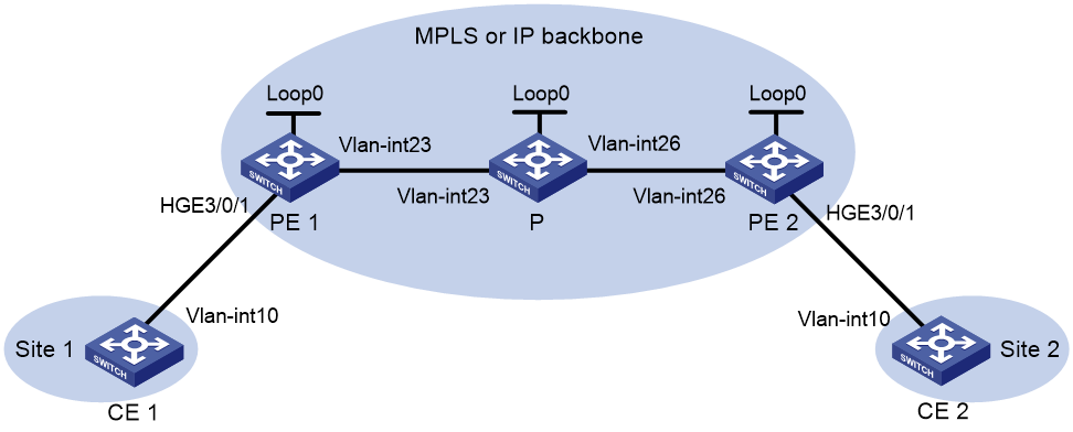
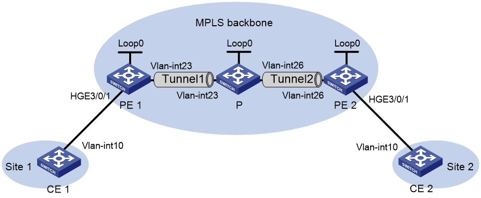
Example: Configuring a remote connection between singlehomed sites
Network configuration
As shown in Figure 8, set up a remote connection between CE 1 and CE 2 for users in VLAN 10 of site 1 and site 2 to communicate through EVPN VPWS over the MPLS or IP backbone network.
|
Device |
Interface |
IP address |
Device |
Interface |
IP address |
|
CE 1 |
Vlan-int10 |
10.1.1.10/24 |
P |
Loop0 |
3.3.3.3/32 |
|
PE 1 |
Loop0 |
1.1.1.1/32 |
|
Vlan-int23 |
11.1.1.2/24 |
|
|
Vlan-int23 |
11.1.1.1/24 |
|
Vlan-int26 |
11.1.2.2/24 |
|
CE 2 |
Vlan-int10 |
10.1.1.20/24 |
PE 2 |
Loop0 |
2.2.2.2/32 |
|
|
|
|
|
Vlan-int26 |
11.1.2.1/24 |
Procedure
1. Create VLANs on all devices and assign interfaces to the VLANs. (Details not shown.)
2. Configure CE 1.
<CE1> system-view
[CE1] interface vlan-interface 10
[CE1-Vlan-interface10] ip address 10.1.1.10 24
[CE1-Vlan-interface10] quit
3. Configure PE 1:
# Configure the LSR ID.
<PE1> system-view
[PE1] interface loopback 0
[PE1-LoopBack0] ip address 1.1.1.1 32
[PE1-LoopBack0] quit
[PE1] mpls lsr-id 1.1.1.1
# Enable L2VPN.
[PE1] l2vpn enable
# Enable global LDP.
[PE1] mpls ldp
[PE1-ldp] quit
# Configure VLAN-interface 23 (the interface connected to the P device), and enable LDP on the interface.
[PE1] interface vlan-interface 23
[PE1-Vlan-interface23] ip address 11.1.1.1 24
[PE1-Vlan-interface23] mpls enable
[PE1-Vlan-interface23] mpls ldp enable
[PE1-Vlan-interface23] undo shutdown
[PE1-Vlan-interface23] quit
# Configure OSPF for LDP to create LSPs.
[PE1] ospf
[PE1-ospf-1] area 0
[PE1-ospf-1-area-0.0.0.0] network 11.1.1.0 0.0.0.255
[PE1-ospf-1-area-0.0.0.0] network 1.1.1.1 0.0.0.0
[PE1-ospf-1-area-0.0.0.0] quit
[PE1-ospf-1] quit
# Create an IBGP connection to PE 2, and enable BGP to advertise L2VPN information to PE 2.
[PE1] bgp 100
[PE1-bgp-default] peer 2.2.2.2 as-number 100
[PE1-bgp-default] peer 2.2.2.2 connect-interface loopback 0
[PE1-bgp-default] address-family l2vpn evpn
[PE1-bgp-default-evpn] peer 2.2.2.2 enable
[PE1-bgp-default-evpn] quit
[PE1-bgp-default] quit
# Configure Ethernet service instance 1000 to match VLAN 10 on HundredGigE 3/0/1 (the interface connected to CE 1).
[PE1] interface hundredgige 3/0/1
[PE1-HundredGigE3/0/1] service-instance 1000
[PE1-HundredGigE3/0/1-srv1000] encapsulation s-vid 10
[PE1-HundredGigE3/0/1-srv1000] quit
[PE1-HundredGigE3/0/1] quit
# Create a cross-connect group named vpna, create an EVPN instance for it, and enable MPLS encapsulation. Configure an RD and route targets for the EVPN instance.
[PE1] xconnect-group vpna
[PE1-xcg-vpna] evpn encapsulation mpls
[PE1-xcg-vpna-evpn-mpls] route-distinguisher 1:1
[PE1-xcg-vpna-evpn-mpls] vpn-target 1:1 export-extcommunity
[PE1-xcg-vpna-evpn-mpls] vpn-target 1:1 import-extcommunity
[PE1-xcg-vpna-evpn-mpls] quit
# Create cross-connect pw1 and map Ethernet service instance 1000 on HundredGigE 3/0/1 to it. Create an EVPN PW on the cross-connect.
[PE1-xcg-vpna] connection pw1
[PE1-xcg-vpna-pw1] ac interface hundredgige 3/0/1 service-instance 1000
[PE1-xcg-vpna-pw1-HundredGigE3/0/1-srv1000] quit
[PE1-xcg-vpna-pw1] evpn local-service-id 1 remote-service-id 2
[PE1-xcg-vpna-pw1-1-2] quit
[PE1-xcg-vpna-pw1] quit
[PE1-xcg-vpna] quit
4. Configure the P device:
# Configure the LSR ID.
<P> system-view
[P] interface loopback 0
[P-LoopBack0] ip address 3.3.3.3 32
[P-LoopBack0] quit
[P] mpls lsr-id 3.3.3.3
# Enable global LDP.
[P] mpls ldp
[P-ldp] quit
# Configure VLAN-interface 23 (the interface connected to PE 1), and enable LDP on the interface.
[P] interface vlan-interface 23
[P-Vlan-interface23] ip address 11.1.1.2 24
[P-Vlan-interface23] mpls enable
[P-Vlan-interface23] mpls ldp enable
[P-Vlan-interface23] undo shutdown
[P-Vlan-interface23] quit
# Configure VLAN-interface 26 (the interface connected to PE 2), and enable LDP on the interface.
[P] interface vlan-interface 26
[P-Vlan-interface26] ip address 11.1.2.2 24
[P-Vlan-interface26] mpls enable
[P-Vlan-interface26] mpls ldp enable
[P-Vlan-interface26] undo shutdown
[P-Vlan-interface26] quit
# Configure OSPF for LDP to create LSPs.
[P] ospf
[P-ospf-1] area 0
[P-ospf-1-area-0.0.0.0] network 11.1.1.0 0.0.0.255
[P-ospf-1-area-0.0.0.0] network 11.1.2.0 0.0.0.255
[P-ospf-1-area-0.0.0.0] network 3.3.3.3 0.0.0.0
[P-ospf-1-area-0.0.0.0] quit
[P-ospf-1] quit
5. Configure PE 2:
# Configure the LSR ID.
<PE2> system-view
[PE2] interface loopback 0
[PE2-LoopBack0] ip address 2.2.2.2 32
[PE2-LoopBack0] quit
[PE2] mpls lsr-id 2.2.2.2
# Enable L2VPN.
[PE2] l2vpn enable
# Enable global LDP.
[PE2] mpls ldp
[PE2-ldp] quit
# Configure VLAN-interface 26 (the interface connected to the P device), and enable LDP on the interface.
[PE2] interface vlan-interface 26
[PE2-Vlan-interface26] ip address 11.1.2.1 24
[PE2-Vlan-interface26] mpls enable
[PE2-Vlan-interface26] mpls ldp enable
[PE2-Vlan-interface26] undo shutdown
[PE2-Vlan-interface26] quit
# Configure OSPF for LDP to create LSPs.
[PE2] ospf
[PE2-ospf-1] area 0
[PE2-ospf-1-area-0.0.0.0] network 2.2.2.2 0.0.0.0
[PE2-ospf-1-area-0.0.0.0] network 11.1.2.0 0.0.0.255
[PE2-ospf-1-area-0.0.0.0] quit
[PE2-ospf-1] quit
# Create an IBGP connection to PE 1, and enable BGP to advertise L2VPN information to PE 1.
[PE2] bgp 100
[PE2-bgp-default] peer 1.1.1.1 as-number 100
[PE2-bgp-default] peer 1.1.1.1 connect-interface loopback 0
[PE2-bgp-default] address-family l2vpn evpn
[PE2-bgp-default-evpn] peer 1.1.1.1 enable
[PE2-bgp-default-evpn] quit
[PE2-bgp-default] quit
# Configure Ethernet service instance 1000 to match VLAN 10 on HundredGigE 3/0/1 (the interface connected to CE 2).
[PE2] interface hundredgige 3/0/1
[PE2-HundredGigE3/0/1] service-instance 1000
[PE2-HundredGigE3/0/1-srv1000] encapsulation s-vid 10
[PE2-HundredGigE3/0/1-srv1000] quit
[PE2-HundredGigE3/0/1] quit
# Create a cross-connect group named vpna, create an EVPN instance for it, and enable MPLS encapsulation. Configure an RD and route targets for the EVPN instance.
[PE2] xconnect-group vpna
[PE2-xcg-vpna] evpn encapsulation mpls
[PE2-xcg-vpna-evpn-mpls] route-distinguisher 1:1
[PE2-xcg-vpna-evpn-mpls] vpn-target 1:1 export-extcommunity
[PE2-xcg-vpna-evpn-mpls] vpn-target 1:1 import-extcommunity
[PE2-xcg-vpna-evpn-mpls] quit
# Create cross-connect pw1 and map Ethernet service instance 1000 on HundredGigE 3/0/1 to it. Create an EVPN PW on the cross-connect.
[PE2-xcg-vpna] connection pw1
[PE2-xcg-vpna-pw1] ac interface hundredgige 3/0/1 service-instance 1000
[PE2-xcg-vpna-pw1-HundredGigE3/0/1-srv1000] quit
[PE2-xcg-vpna-pw1] evpn local-service-id 2 remote-service-id 1
[PE2-xcg-vpna-pw1-2-1] quit
[PE2-xcg-vpna-pw1] quit
[PE2-xcg-vpna] quit
6. Configure CE 2.
<CE2> system-view
[CE2] interface vlan-interface 10
[CE2-Vlan-interface10] ip address 10.1.1.20 24
[CE2-Vlan-interface10] quit
Verifying the configuration
# Verify that an EVPN PW has been established between PE 1 and PE 2.
[PE1] display l2vpn pw
Flags: M - main, B - backup, E - ecmp, BY - bypass, H - hub link, S - spoke link
N - no split horizon, A - administration, ABY - ac-bypass
PBY - pw-bypass
Total number of PWs: 1
1 up, 0 blocked, 0 down, 0 defect, 0 idle, 0 duplicate
Xconnect-group Name: vpna
Peer PWID/RmtSite/SrvID In/Out Label Proto Flag Link ID State
2.2.2.2 2 710127/710127 EVPN M 0 Up
# Verify that the EVPN information about the cross-connect on PE 1 is correct.
<Sysname> display evpn xconnect-group
Flags: P - Primary, B - Backup, C - Control word
Xconnect group name: vpna
Connection Name: pw1
ESI : 0000.0000.0000.0000.0000
Local service ID : 1
Remote service ID : 2
Control word : Disable
In label : 502
Local MTU : 1500
AC State : Up
PW type : VLAN
Nexthop ESI Out label Flags MTU State
2.2.2.2 0000.0000.0000.0000.0000 1299 P 1500 Up
# Verify that the EVPN information about the cross-connect on PE 2 is correct.
[PE2] display l2vpn pw
Flags: M - main, B - backup, E - ecmp, BY - bypass, H - hub link, S - spoke link
N - no split horizon, A - administration, ABY - ac-bypass
PBY - pw-bypass
Total number of PWs: 1
1 up, 0 blocked, 0 down, 0 defect, 0 idle, 0 duplicate
Xconnect-group Name: vpna
Peer PWID/RmtSite/SrvID In/Out Label Proto Flag Link ID State
1.1.1.1 1 710127/710127 EVPN M 0 Up
# Verify that CE 1 and CE 2 can ping each other. (Details not shown.)
Example: Configuring PW concatenation
Network configuration
As shown in Figure 9:
· Set up an MPLS TE tunnel between each PE and the P device, and configure each MPLS TE tunnel to convey an EVPN PW.
· Concatenate the EVPN PWs on the P device for the CEs to communicate at Layer 2 over the MPLS backbone.
|
Device |
Interface |
IP address |
Device |
Interface |
IP address |
|
CE 1 |
Vlan-int10 |
100.1.1.1/24 |
P |
Loop0 |
192.4.4.4/32 |
|
PE 1 |
Loop0 |
192.2.2.2/32 |
|
Vlan-int23 |
23.1.1.2/24 |
|
|
Vlan-int23 |
23.1.1.1/24 |
|
Vlan-int26 |
26.2.2.2/24 |
|
CE 2 |
Vlan-int10 |
100.1.1.2/24 |
PE 2 |
Loop0 |
192.3.3.3/32 |
|
|
|
|
|
Vlan-int26 |
26.2.2.1/24 |
Procedure
1. Create VLANs on all devices and assign interfaces to the VLANs. (Details not shown.)
2. Configure CE 1.
<CE1> system-view
[CE1] interface vlan-interface 10
[CE1-Vlan-interface10] ip address 100.1.1.1 24
[CE1-Vlan-interface10] quit
3. Configure PE 1:
# Configure the LSR ID.
<PE1> system-view
[PE1] interface loopback 0
[PE1-LoopBack0] ip address 192.2.2.2 32
[PE1-LoopBack0] quit
[PE1] mpls lsr-id 192.2.2.2
# Enable L2VPN.
[PE1] l2vpn enable
# Enable global LDP.
[PE1] mpls ldp
[PE1-ldp] quit
# Set up an MPLS TE tunnel between PE 1 and the P device as described in MPLS TE configuration in MPLS Configuration Guide.
# On HundredGigE 3/0/1, configure Ethernet service instance 1000 to match VLAN 10.
[PE1] interface hundredgige 3/0/1
[PE1-HundredGigE3/0/1] service-instance 1000
[PE1-HundredGigE3/0/1-srv1000] encapsulation s-vid 10
[PE1-HundredGigE3/0/1-srv1000] quit
[PE1-HundredGigE3/0/1] quit
# Create a cross-connect group named vpna, create an EVPN instance for it, and enable MPLS encapsulation. Configure an RD and route targets for the EVPN instance.
[PE1] xconnect-group vpna
[PE1-xcg-vpna] evpn encapsulation mpls
[PE1-xcg-vpna-evpn-mpls] route-distinguisher 1:1
[PE1-xcg-vpna-evpn-mpls] vpn-target 1:1 export-extcommunity
[PE1-xcg-vpna-evpn-mpls] vpn-target 1:2 import-extcommunity
[PE1-xcg-vpna-evpn-mpls] quit
# Create cross-connect pw1 and map Ethernet service instance 1000 on HundredGigE 3/0/1 to it. Create an EVPN PW on the cross-connect.
[PE1-xcg-vpna] connection pw1
[PE1-xcg-vpna-pw1] evpn local-service-id 2 remote-service-id 1
[PE1-xcg-vpna-pw1-2-1] quit
[PE1-xcg-vpna-pw1] ac interface hundredgige 3/0/1 service-instance 1000
[PE1-xcg-vpna-pw1-HundredGigE3/0/1-srv1000] quit
[PE1-xcg-vpna-pw1] quit
[PE1-xcg-vpna] quit
# Create an IBGP connection to the P device, and enable BGP to advertise BGP EVPN routes to the P device.
[PE1] bgp 100
[PE1-bgp-default] peer 192.4.4.4 as-number 100
[PE1-bgp-default] peer 192.4.4.4 connect-interface LoopBack0
[PE1-bgp-default] address-family l2vpn evpn
[PE1-bgp-default-evpn] peer 194.4.4.4 enable
[PE1-bgp-default-evpn] quit
[PE1-bgp-default] quit
4. Configure the P device:
# Configure the LSR ID.
<P> system-view
[P] interface loopback 0
[P-LoopBack0] ip address 192.4.4.4 32
[P-LoopBack0] quit
[P] mpls lsr-id 192.4.4.4
# Enable L2VPN.
[P] l2vpn enable
# Enable global LDP.
[P] mpls ldp
[P-ldp] quit
# Set up an MPLS TE tunnel to each PE as described in MPLS TE configuration in MPLS Configuration Guide.
# Create a cross-connect group named vpna, create an EVPN instance for it, and enable MPLS encapsulation. Configure an RD and route targets for the EVPN instance.
[P] xconnect-group vpna
[P-xcg-vpna] evpn encapsulation mpls
[P-xcg-vpna-evpn-mpls] route-distinguisher 1:1
[P-xcg-vpna-evpn-mpls] vpn-target 1:2 export-extcommunity
[P-xcg-vpna-evpn-mpls] vpn-target 1:1 1:3 import-extcommunity
[P-xcg-vpna-evpn-mpls] quit
# Create cross-connect pw1 and create two EVPN PWs on the cross-connect.
[P-xcg-vpna] connection pw1
[P-xcg-vpna-pw1] evpn local-service-id 1 remote-service-id 2
[P-xcg-vpna-pw1-1-2] quit
[P-xcg-vpna-pw1] evpn local-service-id 3 remote-service-id 4
[P-xcg-vpna-pw1-3-4] quit
[P-xcg-vpna-pw1] quit
[P-xcg-vpna] quit
# Create an IBGP connection to each PE, and enable BGP to advertise BGP EVPN routes to the PEs.
[P] bgp 100
[P-bgp-default] peer 192.2.2.2 as-number 100
[P-bgp-default] peer 192.2.2.2 connect-interface LoopBack0
[P-bgp-default] peer 192.3.3.3 as-number 100
[P-bgp-default] peer 192.3.3.3 connect-interface LoopBack0
[P-bgp-default] address-family l2vpn evpn
[P-bgp-default-evpn] peer 192.2.2.2 enable
[P-bgp-default-evpn] peer 192.3.3.3 enable
[P-bgp-default-evpn] quit
[P-bgp-default] quit
5. Configure PE 2:
# Configure the LSR ID.
<PE2> system-view
[PE2] interface loopback 0
[PE2-LoopBack0] ip address 192.3.3.3 32
[PE2-LoopBack0] quit
[PE2] mpls lsr-id 192.3.3.3
# Enable L2VPN.
[PE2] l2vpn enable
# Enable global LDP.
[PE2] mpls ldp
[PE2-ldp] quit
# Set up an MPLS TE tunnel between PE 2 and the P device as described in MPLS TE configuration in MPLS Configuration Guide.
# On HundredGigE 3/0/1, configure Ethernet service instance 1000 to match VLAN 10.
[PE2] interface hundredgige 3/0/1
[PE2-HundredGigE3/0/1] service-instance 1000
[PE2-HundredGigE3/0/1-srv1000] encapsulation s-vid 10
[PE2-HundredGigE3/0/1-srv1000] quit
[PE2-HundredGigE3/0/1] quit
# Create a cross-connect group named vpna, create an EVPN instance for it, and enable MPLS encapsulation. Configure an RD and route targets for the EVPN instance.
[PE2] xconnect-group vpna
[PE2-xcg-vpna] evpn encapsulation mpls
[PE2-xcg-vpna-evpn-mpls] route-distinguisher 1:1
[PE2-xcg-vpna-evpn-mpls] vpn-target 1:3 export-extcommunity
[PE2-xcg-vpna-evpn-mpls] vpn-target 1:2 import-extcommunity
[PE2-xcg-vpna-evpn-mpls] quit
# Create cross-connect pw1 and map Ethernet service instance 1000 on HundredGigE 3/0/1 to it. Create an EVPN PW on the cross-connect.
[PE2-xcg-vpna] connection pw1
[PE2-xcg-vpna-pw1] evpn local-service-id 4 remote-service-id 3
[PE2-xcg-vpna-pw1-4-3] quit
[PE2-xcg-vpna-pw1] ac interface hundredgige 3/0/1 service-instance 1000
[PE2-xcg-vpna-pw1-HundredGigE3/0/1-srv1000] quit
[PE2-xcg-vpna-pw1] quit
[PE2-xcg-vpna] quit
# Create an IBGP connection to the P device, and enable BGP to advertise BGP EVPN routes to the P device.
[PE2] bgp 100
[PE2-bgp-default] peer 192.4.4.4 as-number 100
[PE2-bgp-default] peer 192.4.4.4 connect-interface LoopBack0
[PE2-bgp-default] address-family l2vpn evpn
[PE2-bgp-default-evpn] peer 192.4.4.4 enable
[PE2-bgp-default-evpn] quit
[PE2-bgp-default] quit
6. Configure CE 2.
<CE2> system-view
[CE2] interface vlan-interface 10
[CE2-Vlan-interface10] ip address 100.1.1.2 24
[CE2-Vlan-interface10] quit
Verifying the configuration
# Verify that an EVPN PW has been established on PE 1.
[PE1] display l2vpn pw
Flags: M - main, B - backup, E - ecmp, BY - bypass, H - hub link, S - spoke link
N - no split horizon, A - administration, ABY - ac-bypass
PBY - pw-bypass
Total number of PWs: 1
1 up, 0 blocked, 0 down, 0 defect, 0 idle, 0 duplicate
Xconnect-group Name: vpna
Peer PWID/RmtSite/SrvID In/Out Label Proto Flag Link ID State
192.4.4.4 1 1151/1150 EVPN M 0 Up
# Verify that two EVPN PWs are concatenated on the P device.
[P] display l2vpn pw
Flags: M - main, B - backup, E - ecmp, BY - bypass, H - hub link, S - spoke link
N - no split horizon, A - administration, ABY - ac-bypass
PBY - pw-bypass
Total number of PWs: 2
2 up, 0 blocked, 0 down, 0 defect, 0 idle, 0 duplicate
Xconnect-group Name: vpna
Peer PWID/RmtSite/SrvID In/Out Label Proto Flag Link ID State
192.2.2.2 2 1150/1151 EVPN M 0 Up
192.3.3.3 4 1151/1151 EVPN M 1 Up
# Verify that an EVPN PW has been established on PE 2.
[PE2] display l2vpn pw
Flags: M - main, B - backup, E - ecmp, BY - bypass, H - hub link, S - spoke link
N - no split horizon, A - administration, ABY - ac-bypass
PBY - pw-bypass
Total number of PWs: 1
1 up, 0 blocked, 0 down, 0 defect, 0 idle, 0 duplicate
Xconnect-group Name: vpna
Peer PWID/RmtSite/SrvID In/Out Label Proto Flag Link ID State
192.4.4.4 3 1151/1151 EVPN M 0 Up
# Verify that CE 1 and CE 2 can ping each other. (Details not shown.)
Example: Configuring inter-AS option A
Network configuration
As shown in Figure 10:
· Establish an EVPN PW between the PE and the ASBR in each AS.
· Associate HundredGigE 3/0/1 with the EVPN PW on each ASBR.
· Associate the Ethernet service instance on HundredGigE 3/0/1 with the EVPN PW on each PE.
· Run OSPF on the MPLS backbone of each AS.

|
Device |
Interface |
IP address |
Device |
Interface |
IP address |
|
CE 1 |
Vlan-int10 |
100.1.1.1/24 |
ASBR 1 |
Loop0 |
192.2.2.2/32 |
|
PE 1 |
Loop0 |
192.1.1.1/32 |
|
Vlan-int23 |
23.1.1.2/24 |
|
|
Vlan-int23 |
23.1.1.1/24 |
|
Vlan-int26 |
26.2.2.2/24 |
|
PE 2 |
Loop0 |
192.4.4.4/32 |
ASBR 2 |
Loop0 |
192.3.3.3/32 |
|
|
Vlan-int22 |
22.2.2.1/24 |
|
Vlan-int26 |
26.2.2.3/24 |
|
CE 2 |
Vlan-int10 |
100.1.1.2/24 |
|
Vlan-int22 |
22.2.2.3/24 |
Procedure
1. Create VLANs on all devices and assign interfaces to the VLANs. (Details not shown.)
2. Configure CE 1.
<CE1> system-view
[CE1] interface vlan-interface 10
[CE1-Vlan-interface10] ip address 100.1.1.1 24
[CE1-Vlan-interface10] quit
3. Configure PE 1:
# Configure the LSR ID.
<PE1> system-view
[PE1] interface loopback 0
[PE1-LoopBack0] ip address 192.1.1.1 32
[PE1-LoopBack0] quit
[PE1] mpls lsr-id 192.1.1.1
# Enable L2VPN.
[PE1] l2vpn enable
# Enable global LDP.
[PE1] mpls ldp
[PE1-ldp] quit
# Enable LDP on VLAN-interface 23, the interface connected to ASBR 1.
[PE1] interface vlan-interface 23
[PE1-Vlan-interface23] ip address 23.1.1.1 24
[PE1-Vlan-interface23] mpls enable
[PE1-Vlan-interface23] mpls ldp enable
[PE1-Vlan-interface23] quit
# Configure OSPF for LDP to create LSPs.
[PE1] ospf
[PE1-ospf-1] area 0
[PE1-ospf-1-area-0.0.0.0] network 23.1.1.0 0.0.0.255
[PE1-ospf-1-area-0.0.0.0] network 192.1.1.1 0.0.0.0
[PE1-ospf-1-area-0.0.0.0] quit
[PE1-ospf-1] quit
# On HundredGigE 3/0/1, configure Ethernet service instance 1000 to match VLAN 10.
[PE1] interface hundredgige 3/0/1
[PE1-HundredGigE3/0/1] service-instance 1000
[PE1-HundredGigE3/0/1-srv1000] encapsulation s-vid 10
[PE1-HundredGigE3/0/1-srv1000] quit
[PE1-HundredGigE3/0/1] quit
# Create a cross-connect group named vpna, create an EVPN instance for it, and enable MPLS encapsulation. Configure an RD and route targets for the EVPN instance.
[PE1] xconnect-group vpna
[PE1-xcg-vpna] evpn encapsulation mpls
[PE1-xcg-vpna-evpn-mpls] route-distinguisher 1:1
[PE1-xcg-vpna-evpn-mpls] vpn-target 1:1 export-extcommunity
[PE1-xcg-vpna-evpn-mpls] vpn-target 1:2 import-extcommunity
[PE1-xcg-vpna-evpn-mpls] quit
# Create cross-connect pw1 and map Ethernet service instance 1000 on HundredGigE 3/0/1 to it. Create an EVPN PW on the cross-connect.
[PE1-xcg-vpna] connection pw1
[PE1-xcg-vpna-pw1] evpn local-service-id 2 remote-service-id 1
[PE1-xcg-vpna-pw1-2-1] quit
[PE1-xcg-vpna-pw1] ac interface hundredgige 3/0/1 service-instance 1000
[PE1-xcg-vpna-pw1-HundredGigE3/0/1-srv1000] quit
[PE1-xcg-vpna-pw1] quit
[PE1-xcg-vpna] quit
# Create an IBGP connection to ASBR 1, and enable BGP to advertise BGP EVPN routes to ASBR 1.
[PE1] bgp 100
[PE1-bgp-default] peer 192.2.2.2 as-number 100
[PE1-bgp-default] peer 192.2.2.2 connect-interface LoopBack0
[PE1-bgp-default] address-family l2vpn evpn
[PE1-bgp-default-evpn] peer 192.2.2.2 enable
[PE1-bgp-default-evpn] quit
[PE1-bgp-default] quit
4. Configure ASBR 1:
# Configure the LSR ID.
<ASBR1> system-view
[ASBR1] interface loopback 0
[ASBR1-LoopBack0] ip address 192.2.2.2 32
[ASBR1-LoopBack0] quit
[ASBR1] mpls lsr-id 192.2.2.2
# Enable L2VPN.
[ASBR1] l2vpn enable
# Enable global LDP.
[ASBR1] mpls ldp
[ASBR1-ldp] quit
# Enable LDP on VLAN-interface 23, the interface connected to PE 1.
[ASBR1] interface vlan-interface 23
[ASBR1-Vlan-interface23] ip address 23.1.1.2 24
[ASBR1-Vlan-interface23] mpls enable
[ASBR1-Vlan-interface23] mpls ldp enable
[ASBR1-Vlan-interface23] quit
# Configure OSPF for LDP to create LSPs.
[ASBR1] ospf
[ASBR1-ospf-1] area 0
[ASBR1-ospf-1-area-0.0.0.0] network 23.1.1.0 0.0.0.255
[ASBR1-ospf-1-area-0.0.0.0] network 192.2.2.2 0.0.0.0
[ASBR1-ospf-1-area-0.0.0.0] quit
[ASBR1-ospf-1] quit
# On HundredGigE 3/0/1, configure Ethernet service instance 1000 to match VLAN 10.
[ASBR1] interface hundredgige 3/0/1
[ASBR1-HundredGigE3/0/1] service-instance 1000
[ASBR1-HundredGigE3/0/1-srv1000] encapsulation s-vid 10
[ASBR1-HundredGigE3/0/1-srv1000] quit
[ASBR1-HundredGigE3/0/1] quit
# Create a cross-connect group named vpna, create an EVPN instance for it, and enable MPLS encapsulation. Configure an RD and route targets for the EVPN instance.
[ASBR1] xconnect-group vpna
[ASBR1-xcg-vpna] evpn encapsulation mpls
[ASBR1-xcg-vpna-evpn-mpls] route-distinguisher 1:1
[ASBR1-xcg-vpna-evpn-mpls] vpn-target 1:2 export-extcommunity
[ASBR1-xcg-vpna-evpn-mpls] vpn-target 1:1 import-extcommunity
[ASBR1-xcg-vpna-evpn-mpls] quit
# Create cross-connect pw1 and map Ethernet service instance 1000 on HundredGigE 3/0/1 (the interface connected to ASBR 2) to it. Create an EVPN PW on the cross-connect.
[ASBR1-xcg-vpna] connection pw1
[ASBR1-xcg-vpna-pw1] evpn local-service-id 1 remote-service-id 2
[ASBR1-xcg-vpna-pw1-1-2] quit
[ASBR1-xcg-vpna-pw1] ac interface hundredgige 3/0/1 service-instance 1000
[ASBR1-xcg-vpna-pw1-HundredGigE3/0/1-srv1000] quit
[ASBR1-xcg-vpna-pw1] quit
[ASBR1-xcg-vpna] quit
# Create an IBGP connection to PE 1, and enable BGP to advertise BGP EVPN routes to PE 1.
[ASBR1] bgp 100
[ASBR1-bgp-default] peer 192.1.1.1 as-number 100
[ASBR1-bgp-default] peer 192.1.1.1 connect-interface LoopBack0
[ASBR1-bgp-default] address-family l2vpn evpn
[ASBR1-bgp-default-evpn] peer 192.1.1.1 enable
[ASBR1-bgp-default-evpn] quit
[ASBR1-bgp-default] quit
5. Configure ASBR 2:
# Configure the LSR ID.
<ASBR2> system-view
[ASBR2] interface loopback 0
[ASBR2-LoopBack0] ip address 192.3.3.3 32
[ASBR2-LoopBack0] quit
[ASBR2] mpls lsr-id 192.3.3.3
# Enable L2VPN.
[ASBR2] l2vpn enable
# Enable global LDP.
[ASBR2] mpls ldp
[ASBR2-ldp] quit
# Enable LDP on VLAN-interface 22, the interface connected to PE 2.
[ASBR2] interface vlan-interface 22
[ASBR2-Vlan-interface22] ip address 22.2.2.3 24
[ASBR2-Vlan-interface22] mpls enable
[ASBR2-Vlan-interface22] mpls ldp enable
[ASBR2-Vlan-interface22] quit
# Configure OSPF for LDP to create LSPs.
[ASBR2] ospf
[ASBR2-ospf-1] area 0
[ASBR2-ospf-1-area-0.0.0.0] network 22.2.2.0 0.0.0.255
[ASBR2-ospf-1-area-0.0.0.0] network 192.3.3.3 0.0.0.0
[ASBR2-ospf-1-area-0.0.0.0] quit
[ASBR2-ospf-1] quit
# On HundredGigE 3/0/1, configure Ethernet service instance 1000 to match VLAN 10.
[ASBR2] interface hundredgige 3/0/1
[ASBR2-HundredGigE3/0/1] service-instance 1000
[ASBR2-HundredGigE3/0/1-srv1000] encapsulation s-vid 10
[ASBR2-HundredGigE3/0/1-srv1000] quit
[ASBR2-HundredGigE3/0/1] quit
# Create a cross-connect group named vpna, create an EVPN instance for it, and enable MPLS encapsulation. Configure an RD and route targets for the EVPN instance.
[ASBR2] xconnect-group vpna
[ASBR2-xcg-vpna] evpn encapsulation mpls
[ASBR2-xcg-vpna-evpn-mpls] route-distinguisher 1:1
[ASBR2-xcg-vpna-evpn-mpls] vpn-target 2:2 export-extcommunity
[ASBR2-xcg-vpna-evpn-mpls] vpn-target 2:1 import-extcommunity
[ASBR2-xcg-vpna-evpn-mpls] quit
# Create cross-connect pw1 and map Ethernet service instance 1000 on HundredGigE 3/0/1 (the interface connected to ASBR 1) to it. Create an EVPN PW on the cross-connect.
[ASBR2-xcg-vpna] connection pw1
[ASBR2-xcg-vpna-pw1] evpn local-service-id 3 remote-service-id 4
[ASBR2-xcg-vpna-pw1-3-4] quit
[ASBR2-xcg-vpna-pw1] ac interface hundredgige 3/0/1 service-instance 1000
[ASBR2-xcg-vpna-pw1-HundredGigE3/0/1-srv1000] quit
[ASBR2-xcg-vpna-pw1] quit
[ASBR2-xcg-vpna] quit
# Create an IBGP connection to PE 2, and enable BGP to advertise BGP EVPN routes to PE 2.
[ASBR2] bgp 200
[ASBR2-bgp-default] peer 192.4.4.4 as-number 200
[ASBR2-bgp-default] peer 192.4.4.4 connect-interface LoopBack0
[ASBR2-bgp-default] address-family l2vpn evpn
[ASBR2-bgp-default-evpn] peer 192.4.4.4 enable
[ASBR2-bgp-default-evpn] quit
[ASBR2-bgp-default] quit
6. Configure PE 2:
# Configure the LSR ID.
<PE2> system-view
[PE2] interface loopback 0
[PE2-LoopBack0] ip address 192.4.4.4 32
[PE2-LoopBack0] quit
[PE2] mpls lsr-id 192.4.4.4
# Enable L2VPN.
[PE2] l2vpn enable
# Enable global LDP.
[PE2] mpls ldp
[PE2-ldp] quit
# Enable LDP on VLAN-interface 22, the interface connected to ASBR 2.
[PE2] interface vlan-interface 22
[PE2-Vlan-interface22] ip address 22.2.2.1 24
[PE2-Vlan-interface22] mpls enable
[PE2-Vlan-interface22] mpls ldp enable
[PE2-Vlan-interface22] quit
# On HundredGigE 3/0/1, configure Ethernet service instance 1000 to match VLAN 10.
[PE2] interface hundredgige 3/0/1
[PE2-HundredGigE3/0/1] service-instance 1000
[PE2-HundredGigE3/0/1-srv1000] encapsulation s-vid 10
[PE2-HundredGigE3/0/1-srv1000] quit
[PE2-HundredGigE3/0/1] quit
# Configure OSPF for LDP to create LSPs.
[PE2] ospf
[PE2-ospf-1] area 0
[PE2-ospf-1-area-0.0.0.0] network 192.4.4.4 0.0.0.0
[PE2-ospf-1-area-0.0.0.0] network 22.2.2.0 0.0.0.255
[PE2-ospf-1-area-0.0.0.0] quit
[PE2-ospf-1] quit
# Create a cross-connect group named vpna, create an EVPN instance for it, and enable MPLS encapsulation. Configure an RD and route targets for the EVPN instance.
[PE2] xconnect-group vpna
[PE2-xcg-vpna] evpn encapsulation mpls
[PE2-xcg-vpna-evpn-mpls] route-distinguisher 1:1
[PE2-xcg-vpna-evpn-mpls] vpn-target 2:1 export-extcommunity
[PE2-xcg-vpna-evpn-mpls] vpn-target 2:2 import-extcommunity
[PE2-xcg-vpna-evpn-mpls] quit
# Create cross-connect pw1 and map Ethernet service instance 1000 on HundredGigE 3/0/1 to it. Create an EVPN PW on the cross-connect.
[PE2-xcg-vpna] connection pw1
[PE2-xcg-vpna-pw1] evpn local-service-id 4 remote-service-id 3
[PE2-xcg-vpna-pw1-4-3] quit
[PE2-xcg-vpna-pw1] ac interface hundredgige 3/0/1 service-instance 1000
[PE2-xcg-vpna-pw1-HundredGigE3/0/1-srv1000] quit
[PE2-xcg-vpna-pw1] quit
[PE2-xcg-vpna] quit
# Create an IBGP connection to ASBR 2, and enable BGP to advertise BGP EVPN routes to ASBR 2.
[PE2] bgp 200
[PE2-bgp-default] peer 192.3.3.3 as-number 200
[PE2-bgp-default] peer 192.3.3.3 connect-interface LoopBack0
[PE2-bgp-default] address-family l2vpn evpn
[PE2-bgp-default-evpn] peer 192.3.3.3 enable
[PE2-bgp-default-evpn] quit
[PE2-bgp-default] quit
7. Configure CE 2.
<CE2> system-view
[CE2] interface vlan-interface 10
[CE2-Vlan-interface10] ip address 100.1.1.2 24
[CE2-Vlan-interface10] quit
Verifying the configuration
# Verify that an EVPN PW has been established on PE 1.
[PE1] display l2vpn pw
Flags: M - main, B - backup, E - ecmp, BY - bypass, H - hub link, S - spoke link
N - no split horizon, A - administration, ABY - ac-bypass,
PBY - pw-bypass
Total number of PWs: 1
1 up, 0 blocked, 0 down, 0 defect, 0 idle, 0 duplicate
Xconnect-group Name: vpna
Peer PWID/RmtSite/SrvID In/Out Label Proto Flag Link ID State
192.2.2.2 1 710127/710126 EVPN M 0 Up
# Verify that an EVPN PW has been established on ASBR 1.
[ASBR1] display l2vpn pw
Flags: M - main, B - backup, E - ecmp, BY - bypass, H - hub link, S - spoke link
N - no split horizon, A - administration, ABY - ac-bypass
PBY - pw-bypass
Total number of PWs: 2
2 up, 0 blocked, 0 down, 0 defect, 0 idle, 0 duplicate
Xconnect-group Name: vpna
Peer PWID/RmtSite/SrvID In/Out Label Proto Flag Link ID State
192.1.1.1 2 710126/710127 EVPN M 0 Up
# Verify that an EVPN PW has been established on ASBR 2.
[ASBR2] display l2vpn pw
Flags: M - main, B - backup, E - ecmp, BY - bypass, H - hub link, S - spoke link
N - no split horizon, A - administration, ABY - ac-bypass
PBY - pw-bypass
Total number of PWs: 2
2 up, 0 blocked, 0 down, 0 defect, 0 idle, 0 duplicate
Xconnect-group Name: vpna
Peer PWID/RmtSite/SrvID In/Out Label Proto Flag Link ID State
192.4.4.4 4 710127/710127 EVPN M 1 Up
# Verify that an EVPN PW has been established on PE 2.
[PE2] display l2vpn pw
Flags: M - main, B - backup, E - ecmp, BY - bypass, H - hub link, S - spoke link
N - no split horizon, A - administration, ABY - ac-bypass
PBY - pw-bypass
Total number of PWs: 1
1 up, 0 blocked, 0 down, 0 defect, 0 idle, 0 duplicate
Xconnect-group Name: vpna
Peer PWID/RmtSite/SrvID In/Out Label Proto Flag Link ID State
192.3.3.3 3 710127/710127 EVPN M 0 Up
# Verify that CE 1 and CE 2 can ping each other. (Details not shown.)
Example: Configuring inter-AS option B
Network configuration
As shown in Figure 11:
· Establish an EVPN PW between the PE and the ASBR in each AS, and use LDP to establish the public tunnels that convey the EVPN PWs.
· Establish an EVPN PW between the ASBRs, and configure BGP to advertise labeled IPv4 unicast routes to establish the public tunnel that conveys the EVPN PW.
· Concatenate the EVPN PWs on the ASBRs.

|
Device |
Interface |
IP address |
Device |
Interface |
IP address |
|
CE 1 |
Vlan-int10 |
100.1.1.1/24 |
ASBR 1 |
Loop0 |
192.2.2.2/32 |
|
PE 1 |
Loop0 |
192.1.1.1/32 |
|
Vlan-int23 |
23.1.1.2/24 |
|
|
Vlan-int23 |
23.1.1.1/24 |
|
Vlan-int26 |
26.2.2.2/24 |
|
PE 2 |
Loop0 |
192.4.4.4/32 |
ASBR 2 |
Loop0 |
192.3.3.3/32 |
|
|
Vlan-int22 |
22.2.2.1/24 |
|
Vlan-int26 |
26.2.2.3/24 |
|
CE 2 |
Vlan-int10 |
100.1.1.2/24 |
|
Vlan-int22 |
22.2.2.3/24 |
Procedure
1. Create VLANs on all devices and assign interfaces to the VLANs. (Details not shown.)
2. Configure CE 1.
<CE1> system-view
[CE1] interface vlan-interface 10
[CE1-Vlan-interface10] ip address 100.1.1.1 24
[CE1-Vlan-interface10] quit
3. Configure PE 1:
# Configure the LSR ID.
<PE1> system-view
[PE1] interface loopback 0
[PE1-LoopBack0] ip address 192.1.1.1 32
[PE1-LoopBack0] quit
[PE1] mpls lsr-id 192.1.1.1
# Enable L2VPN.
[PE1] l2vpn enable
# Enable global LDP.
[PE1] mpls ldp
[PE1-ldp] quit
# Enable LDP on VLAN-interface 23, the interface connected to ASBR 1.
[PE1] interface vlan-interface 23
[PE1-Vlan-interface23] ip address 23.1.1.1 24
[PE1-Vlan-interface23] mpls enable
[PE1-Vlan-interface23] mpls ldp enable
[PE1-Vlan-interface23] quit
# Configure OSPF for LDP to create LSPs.
[PE1] ospf
[PE1-ospf-1] area 0
[PE1-ospf-1-area-0.0.0.0] network 23.1.1.0 0.0.0.255
[PE1-ospf-1-area-0.0.0.0] network 192.1.1.1 0.0.0.0
[PE1-ospf-1-area-0.0.0.0] quit
[PE1-ospf-1] quit
# On HundredGigE 3/0/1, configure Ethernet service instance 1000 to match VLAN 10.
[PE1] interface hundredgige 3/0/1
[PE1-HundredGigE3/0/1] service-instance 1000
[PE1-HundredGigE3/0/1-srv1000] encapsulation s-vid 10
[PE1-HundredGigE3/0/1-srv1000] quit
[PE1-HundredGigE3/0/1] quit
# Create a cross-connect group named vpna, create an EVPN instance for it, and enable MPLS encapsulation. Configure an RD and route targets for the EVPN instance.
[PE1] xconnect-group vpna
[PE1-xcg-vpna] evpn encapsulation mpls
[PE1-xcg-vpna-evpn-mpls] route-distinguisher 1:1
[PE1-xcg-vpna-evpn-mpls] vpn-target 1:1 export-extcommunity
[PE1-xcg-vpna-evpn-mpls] vpn-target 1:2 import-extcommunity
[PE1-xcg-vpna-evpn-mpls] quit
# Create cross-connect pw1 and map Ethernet service instance 1000 on HundredGigE 3/0/1 to it. Create an EVPN PW on the cross-connect.
[PE1-xcg-vpna] connection pw1
[PE1-xcg-vpna-pw1] evpn local-service-id 2 remote-service-id 1
[PE1-xcg-vpna-pw1-2-1] quit
[PE1-xcg-vpna-pw1] ac interface hundredgige 3/0/1 service-instance 1000
[PE1-xcg-vpna-pw1-HundredGigE3/0/1-srv1000] quit
[PE1-xcg-vpna-pw1] quit
[PE1-xcg-vpna] quit
# Create an IBGP connection to ASBR 1, and enable BGP to advertise BGP EVPN routes to ASBR 1.
[PE1] bgp 100
[PE1-bgp-default] peer 192.2.2.2 as-number 100
[PE1-bgp-default] peer 192.2.2.2 connect-interface LoopBack0
[PE1-bgp-default] address-family l2vpn evpn
[PE1-bgp-default-evpn] peer 192.2.2.2 enable
[PE1-bgp-default-evpn] quit
[PE1-bgp-default] quit
4. Configure ASBR 1:
# Configure the LSR ID.
<ASBR1> system-view
[ASBR1] interface loopback 0
[ASBR1-LoopBack0] ip address 192.2.2.2 32
[ASBR1-LoopBack0] quit
[ASBR1] mpls lsr-id 192.2.2.2
# Enable L2VPN.
[ASBR1] l2vpn enable
# Enable global LDP.
[ASBR1] mpls ldp
[ASBR1-ldp] quit
# Enable LDP on VLAN-interface 23, the interface connected to PE 1.
[ASBR1] interface vlan-interface 23
[ASBR1-Vlan-interface23] ip address 23.1.1.2 24
[ASBR1-Vlan-interface23] mpls enable
[ASBR1-Vlan-interface23] mpls ldp enable
[ASBR1-Vlan-interface23] quit
# Enable MPLS on VLAN-interface 26, the interface connected to ASBR 2.
[ASBR1] interface vlan-interface 26
[ASBR1-Vlan-interface26] ip address 26.2.2.2 24
[ASBR1-Vlan-interface26] mpls enable
[ASBR1-Vlan-interface26] quit
# Configure OSPF for LDP to create LSPs.
[ASBR1] ospf
[ASBR1-ospf-1] area 0
[ASBR1-ospf-1-area-0.0.0.0] network 23.1.1.0 0.0.0.255
[ASBR1-ospf-1-area-0.0.0.0] network 192.2.2.2 0.0.0.0
[ASBR1-ospf-1-area-0.0.0.0] quit
[ASBR1-ospf-1] quit
# Create an IBGP connection to PE 1, and enable BGP to advertise BGP EVPN routes to PE 1.
[ASBR1] bgp 100
[ASBR1-bgp-default] peer 192.1.1.1 as-number 100
[ASBR1-bgp-default] peer 192.1.1.1 connect-interface LoopBack0
[ASBR1-bgp-default] address-family l2vpn evpn
[ASBR1-bgp-default-evpn] peer 192.1.1.1 enable
[ASBR1-bgp-default-evpn] quit
[ASBR1-bgp-default] quit
# Create an EBGP connection to ASBR 2, and enable BGP to advertise BGP EVPN routes and labeled unicast routes to ASBR 2.
[ASBR1] bgp 100
[ASBR1-bgp-default] peer 26.2.2.3 as-number 200
[ASBR1-bgp-default] address-family ipv4 unicast
[ASBR1-bgp-default-ipv4] import-route direct
[ASBR1-bgp-default-ipv4] peer 26.2.2.3 enable
[ASBR1-bgp-default-ipv4] peer 26.2.2.3 route-policy policy1 export
[ASBR1-bgp-default-ipv4] peer 26.2.2.3 label-route-capability
[ASBR1-bgp-default] address-family l2vpn evpn
[ASBR1-bgp-default-evpn] peer 26.2.2.3 enable
[ASBR1-bgp-default-evpn] quit
[ASBR1-bgp-default] quit
[ASBR1] route-policy policy1 permit node 1
[ASBR1-route-policy-policy1-1] apply mpls-label
[ASBR1-route-policy-policy1-1] quit
# Create a cross-connect group named vpna, create an EVPN instance for it, and enable MPLS encapsulation. Configure an RD and route targets for the EVPN instance.
[ASBR1] xconnect-group vpna
[ASBR1-xcg-vpna] evpn encapsulation mpls
[ASBR1-xcg-vpna-evpn-mpls] route-distinguisher 1:1
[ASBR1-xcg-vpna-evpn-mpls] vpn-target 1:2 export-extcommunity
[ASBR1-xcg-vpna-evpn-mpls] vpn-target 1:1 2:2 import-extcommunity
[ASBR1-xcg-vpna-evpn-mpls] quit
# Create cross-connect pw1 and create two EVPN PWs on the cross-connect.
[ASBR1-xcg-vpna] connection pw1
[ASBR1-xcg-vpna-pw1] evpn local-service-id 1 remote-service-id 2
[ASBR1-xcg-vpna-pw1-1-2] quit
[ASBR1-xcg-vpna-pw1] evpn local-service-id 3 remote-service-id 4
[ASBR1-xcg-vpna-pw1-3-4] quit
[ASBR1-xcg-vpna-pw1] quit
[ASBR1-xcg-vpna] quit
5. Configure ASBR 2:
# Configure the LSR ID.
<ASBR2> system-view
[ASBR2] interface loopback 0
[ASBR2-LoopBack0] ip address 192.3.3.3 32
[ASBR2-LoopBack0] quit
[ASBR2] mpls lsr-id 192.3.3.3
# Enable L2VPN.
[ASBR2] l2vpn enable
# Enable global LDP.
[ASBR2] mpls ldp
[ASBR2-ldp] quit
# Enable LDP on VLAN-interface 22, the interface connected to PE 2.
[ASBR2] interface vlan-interface 22
[ASBR2-Vlan-interface22] ip address 22.2.2.3 24
[ASBR2-Vlan-interface22] mpls enable
[ASBR2-Vlan-interface22] mpls ldp enable
[ASBR2-Vlan-interface22] quit
# Enable MPLS on VLAN-interface 26, the interface connected to ASBR 1.
[ASBR2] interface vlan-interface 26
[ASBR2-Vlan-interface26] ip address 26.2.2.3 24
[ASBR2-Vlan-interface26] mpls enable
[ASBR2-Vlan-interface26] quit
# Configure OSPF for LDP to create LSPs.
[ASBR2] ospf
[ASBR2-ospf-1] area 0
[ASBR2-ospf-1-area-0.0.0.0] network 22.2.2.0 0.0.0.255
[ASBR2-ospf-1-area-0.0.0.0] network 192.3.3.3 0.0.0.0
[ASBR2-ospf-1-area-0.0.0.0] quit
[ASBR2-ospf-1] quit
# Create an IBGP connection to PE 2, and enable BGP to advertise BGP EVPN routes to PE 2.
[ASBR2] bgp 200
[ASBR2-bgp-default] peer 192.4.4.4 as-number 200
[ASBR2-bgp-default] peer 192.4.4.4 connect-interface LoopBack0
[ASBR2-bgp-default] address-family l2vpn evpn
[ASBR2-bgp-default-evpn] peer 192.4.4.4 enable
[ASBR2-bgp-default-evpn] quit
[ASBR2-bgp-default] quit
# Create an EBGP connection to ASBR 1, and enable BGP to advertise BGP EVPN routes and labeled unicast routes to ASBR 1.
[ASBR2] bgp 100
[ASBR2-bgp-default] peer 26.2.2.2 as-number 100
[ASBR2-bgp-default] address-family ipv4 unicast
[ASBR2-bgp-default-ipv4] import-route direct
[ASBR2-bgp-default-ipv4] peer 26.2.2.2 enable
[ASBR2-bgp-default-ipv4] peer 26.2.2.2 route-policy policy1 export
[ASBR2-bgp-default-ipv4] peer 26.2.2.2 label-route-capability
[ASBR2-bgp-default-ipv4] quit
[ASBR2-bgp-default] address-family l2vpn evpn
[ASBR2-bgp-default-evpn] peer 26.2.2.2 enable
[ASBR2-bgp-default-evpn] quit
[ASBR2-bgp-default] quit
[ASBR2] route-policy policy1 permit node 1
[ASBR2-route-policy-policy1-1] apply mpls-label
[ASBR2-route-policy-policy1-1] quit
# Create a cross-connect group named vpna, create an EVPN instance for it, and enable MPLS encapsulation. Configure an RD and route targets for the EVPN instance.
[ASBR2] xconnect-group vpna
[ASBR2-xcg-vpna] evpn encapsulation mpls
[ASBR2-xcg-vpna-evpn-mpls] route-distinguisher 1:1
[ASBR2-xcg-vpna-evpn-mpls] vpn-target 2:2 export-extcommunity
[ASBR2-xcg-vpna-evpn-mpls] vpn-target 1:2 2:1 import-extcommunity
[ASBR2-xcg-vpna-evpn-mpls] quit
# Create cross-connect pw1 and create two EVPN PWs on the cross-connect.
[ASBR2-xcg-vpna] connection pw1
[ASBR2-xcg-vpna-pw1] evpn local-service-id 4 remote-service-id 3
[ASBR2-xcg-vpna-pw1-4-3] quit
[ASBR2-xcg-vpna-pw1] evpn local-service-id 5 remote-service-id 6
[ASBR2-xcg-vpna-pw1-5-6] quit
[ASBR2-xcg-vpna-pw1] quit
[ASBR2-xcg-vpna] quit
6. Configure PE 2:
# Configure the LSR ID.
<PE2> system-view
[PE2] interface loopback 0
[PE2-LoopBack0] ip address 192.4.4.4 32
[PE2-LoopBack0] quit
[PE2] mpls lsr-id 192.4.4.4
# Enable L2VPN.
[PE2] l2vpn enable
# Enable global LDP.
[PE2] mpls ldp
[PE2-ldp] quit
# Enable LDP on VLAN-interface 22, the interface connected to ASBR 2.
[PE2] interface vlan-interface 22
[PE2-Vlan-interface22] ip address 22.2.2.1 24
[PE2-Vlan-interface22] mpls enable
[PE2-Vlan-interface22] mpls ldp enable
[PE2-Vlan-interface22] quit
# Configure OSPF for LDP to create LSPs.
[PE2] ospf
[PE2-ospf-1] area 0
[PE2-ospf-1-area-0.0.0.0] network 192.4.4.4 0.0.0.0
[PE2-ospf-1-area-0.0.0.0] network 22.2.2.0 0.0.0.255
[PE2-ospf-1-area-0.0.0.0] quit
[PE2-ospf-1] quit
# On HundredGigE 3/0/1, configure Ethernet service instance 1000 to match VLAN 10.
[PE2] interface hundredgige 3/0/1
[PE2-HundredGigE3/0/1] service-instance 1000
[PE2-HundredGigE3/0/1-srv1000] encapsulation s-vid 10
[PE2-HundredGigE3/0/1-srv1000] quit
[PE2-HundredGigE3/0/1] quit
# Create a cross-connect group named vpna, create an EVPN instance for it, and enable MPLS encapsulation. Configure an RD and route targets for the EVPN instance.
[PE2] xconnect-group vpna
[PE2-xcg-vpna] evpn encapsulation mpls
[PE2-xcg-vpna-evpn-mpls] route-distinguisher 1:1
[PE2-xcg-vpna-evpn-mpls] vpn-target 2:1 export-extcommunity
[PE2-xcg-vpna-evpn-mpls] vpn-target 2:2 import-extcommunity
[PE2-xcg-vpna-evpn-mpls] quit
# Create cross-connect pw1 and map Ethernet service instance 1000 on HundredGigE 3/0/1 to it. Create an EVPN PW on the cross-connect.
[PE2-xcg-vpna] connection pw1
[PE2-xcg-vpna-pw1] evpn local-service-id 6 remote-service-id 5
[PE2-xcg-vpna-pw1-6-5] quit
[PE2-xcg-vpna-pw1] ac interface hundredgige 3/0/1 service-instance 1000
[PE2-xcg-vpna-pw1-HundredGigE3/0/1-srv1000] quit
[PE2-xcg-vpna-pw1] quit
[PE2-xcg-vpna] quit
# Create an IBGP connection to ASBR 2, and enable BGP to advertise BGP EVPN routes to ASBR 2.
[PE2] bgp 200
[PE2-bgp-default] peer 192.3.3.3 as-number 200
[PE2-bgp-default] peer 192.3.3.3 connect-interface LoopBack0
[PE2-bgp-default] address-family l2vpn evpn
[PE2-bgp-default-evpn] peer 192.3.3.3 enable
[PE2-bgp-default-evpn] quit
[PE2-bgp-default] quit
7. Configure CE 2.
<CE2> system-view
[CE2] interface vlan-interface 10
[CE2-Vlan-interface10] ip address 100.1.1.2 24
[CE2-Vlan-interface10] quit
Verifying the configuration
# Verify that an EVPN PW has been established on PE 1.
[PE1] display l2vpn pw
Flags: M - main, B - backup, E - ecmp, BY - bypass, H - hub link, S - spoke link
N - no split horizon, A - administration, ABY - ac-bypass
PBY - pw-bypass
Total number of PWs: 1
1 up, 0 blocked, 0 down, 0 defect, 0 idle, 0 duplicate
Xconnect-group Name: vpna
Peer PWID/RmtSite/SrvID In/Out Label Proto Flag Link ID State
192.2.2.2 1 710127/710126 EVPN M 0 Up
# Verify that two EVPN PWs are concatenated on ASBR 1.
[ASBR1] display l2vpn pw
Flags: M - main, B - backup, E - ecmp, BY - bypass, H - hub link, S - spoke link
N - no split horizon, A - administration, ABY - ac-bypass
PBY - pw-bypass
Total number of PWs: 2
2 up, 0 blocked, 0 down, 0 defect, 0 idle, 0 duplicate
Xconnect-group Name: vpna
Peer PWID/RmtSite/SrvID In/Out Label Proto Flag Link ID State
192.1.1.1 2 710126/710127 EVPN M 0 Up
26.2.2.3 4 710127/710126 EVPN M 1 Up
# Verify that two EVPN PWs are concatenated on ASBR 2.
[ASBR2] display l2vpn pw
Flags: M - main, B - backup, E - ecmp, BY - bypass, H - hub link, S - spoke link
N - no split horizon, A - administration, ABY - ac-bypass
PBY - pw-bypass
Total number of PWs: 2
2 up, 0 blocked, 0 down, 0 defect, 0 idle, 0 duplicate
Xconnect-group Name: vpna
Peer PWID/RmtSite/SrvID In/Out Label Proto Flag Link ID State
26.2.2.2 3 710126/710127 EVPN M 0 Up
192.4.4.4 6 710127/710127 EVPN M 1 Up
# Verify that an EVPN PW has been established on PE 2.
[PE2] display l2vpn pw
Flags: M - main, B - backup, E - ecmp, BY - bypass, H - hub link, S - spoke link
N - no split horizon, A - administration, ABY - ac-bypass
PBY - pw-bypass
Total number of PWs: 1
1 up, 0 blocked, 0 down, 0 defect, 0 idle, 0 duplicate
Xconnect-group Name: vpna
Peer PWID/RmtSite/SrvID In/Out Label Proto Flag Link ID State
192.3.3.3 5 710127/710127 EVPN M 0 Up
# Verify that CE 1 and CE 2 can ping each other. (Details not shown.)
Example: Configuring inter-AS option C
Network configuration
As shown in Figure 12:
· Configure the PE and the ASBR in each AS to use IBGP to exchange labeled IPv4 routes.
· Configure the PEs to exchange BGP EVPN routes to establish an EVPN PW.
· Establish an EVPN PW between the ASBRs, and configure BGP to advertise labeled IPv4 unicast routes to establish the public tunnel that conveys the EVPN PW.
· Configure a PBR policy on each ASBR for it to insert labels into received routes.
· Configure the ASBRs to exchange labeled IPv4 routes through EBGP.
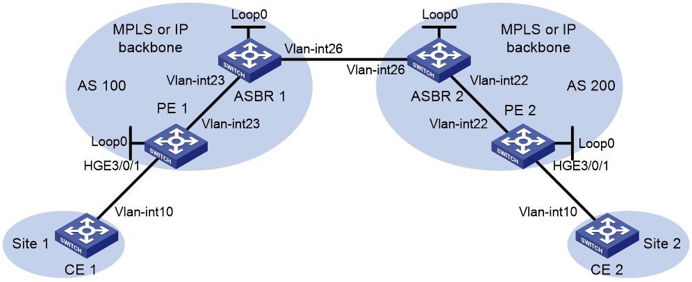
|
Device |
Interface |
IP address |
Device |
Interface |
IP address |
|
CE 1 |
Vlan-int10 |
100.1.1.1/24 |
ASBR 1 |
Loop0 |
192.2.2.2/32 |
|
PE 1 |
Loop0 |
192.1.1.1/32 |
|
Vlan-int23 |
23.1.1.2/24 |
|
|
Vlan-int23 |
23.1.1.1/24 |
|
Vlan-int26 |
26.2.2.2/24 |
|
PE 2 |
Loop0 |
192.4.4.4/32 |
ASBR 2 |
Loop0 |
192.3.3.3/32 |
|
|
Vlan-int22 |
22.2.2.1/24 |
|
Vlan-int26 |
26.2.2.3/24 |
|
CE 2 |
Vlan-int10 |
100.1.1.2/24 |
|
Vlan-int22 |
22.2.2.3/24 |
Procedure
1. Create VLANs on all devices and assign interfaces to the VLANs. (Details not shown.)
2. Configure CE 1.
<CE1> system-view
[CE1] interface vlan-interface 10
[CE1-Vlan-interface10] ip address 100.1.1.1 24
[CE1-Vlan-interface10] quit
3. Configure PE 1:
# Configure the LSR ID.
<PE1> system-view
[PE1] interface loopback 0
[PE1-LoopBack0] ip address 192.1.1.1 32
[PE1-LoopBack0] quit
[PE1] mpls lsr-id 192.1.1.1
# Enable L2VPN.
[PE1] l2vpn enable
# Enable global LDP.
[PE1] mpls ldp
[PE1-ldp] quit
# Enable LDP on VLAN-interface 23, the interface connected to ASBR 1.
[PE1] interface vlan-interface 23
[PE1-Vlan-interface23] ip address 23.1.1.1 24
[PE1-Vlan-interface23] mpls enable
[PE1-Vlan-interface23] mpls ldp enable
[PE1-Vlan-interface23] quit
# Configure OSPF for LDP to create LSPs.
[PE1] ospf
[PE1-ospf-1] area 0
[PE1-ospf-1-area-0.0.0.0] network 23.1.1.0 0.0.0.255
[PE1-ospf-1-area-0.0.0.0] network 192.1.1.1 0.0.0.0
[PE1-ospf-1-area-0.0.0.0] quit
[PE1-ospf-1] quit
# On HundredGigE 3/0/1, configure Ethernet service instance 1000 to match VLAN 10.
[PE1] interface hundredgige 3/0/1
[PE1-HundredGigE3/0/1] service-instance 1000
[PE1-HundredGigE3/0/1-srv1000] encapsulation s-vid 10
[PE1-HundredGigE3/0/1-srv1000] quit
[PE1-HundredGigE3/0/1] quit
# Create a cross-connect group named vpna, create an EVPN instance for it, and enable MPLS encapsulation. Configure an RD and route targets for the EVPN instance.
[PE1] xconnect-group vpna
[PE1-xcg-vpna] evpn encapsulation mpls
[PE1-xcg-vpna-evpn-mpls] route-distinguisher 1:1
[PE1-xcg-vpna-evpn-mpls] vpn-target 1:1 export-extcommunity
[PE1-xcg-vpna-evpn-mpls] vpn-target 2:2 import-extcommunity
[PE1-xcg-vpna-evpn-mpls] quit
# Create cross-connect pw1 and map Ethernet service instance 1000 on HundredGigE 3/0/1 to it. Create an EVPN PW on the cross-connect.
[PE1-xcg-vpna] connection pw1
[PE1-xcg-vpna-pw1] evpn local-service-id 2 remote-service-id 1
[PE1-xcg-vpna-pw1-2-1] quit
[PE1-xcg-vpna-pw1] ac interface hundredgige 3/0/1 service-instance 1000
[PE1-xcg-vpna-pw1-HundredGigE3/0/1-srv1000] quit
[PE1-xcg-vpna-pw1] quit
[PE1-xcg-vpna] quit
# Create an IBGP connection to ASBR 1, and enable BGP to advertise BGP EVPN routes and labeled unicast routes to ASBR 1.
[PE1] bgp 100
[PE1-bgp-default] peer 192.2.2.2 as-number 100
[PE1-bgp-default] peer 192.2.2.2 connect-interface LoopBack0
[PE1-bgp-default] address-family ipv4 unicast
[PE1-bgp-default-ipv4] peer 192.2.2.2 enable
[PE1-bgp-default-ipv4] peer 192.2.2.2 label-route-capability
[PE1-bgp-default-ipv4] quit
[PE1-bgp-default] address-family l2vpn evpn
[PE1-bgp-default-evpn] peer 192.2.2.2 enable
[PE1-bgp-default] quit
# Configure BGP to advertise BGP EVPN routes to PE 2 to establish an EVPN PW.
[PE1] bgp 100
[PE1-bgp-default] peer 192.4.4.4 as-number 200
[PE1-bgp-default] peer 192.4.4.4 connect-interface LoopBack0
[PE1-bgp-default] peer 192.4.4.4 ebgp-max-hop 10
[PE1-bgp-default] address-family l2vpn evpn
[PE1-bgp-default-evpn] peer 192.4.4.4 enable
[PE1-bgp-default-evpn] quit
[PE1-bgp-default] quit
4. Configure ASBR 1:
# Configure the LSR ID.
<ASBR1> system-view
[ASBR1] interface loopback 0
[ASBR1-LoopBack0] ip address 192.2.2.2 32
[ASBR1-LoopBack0] quit
[ASBR1] mpls lsr-id 192.2.2.2
# Enable L2VPN.
[ASBR1] l2vpn enable
# Enable global LDP.
[ASBR1] mpls ldp
[ASBR1-ldp] quit
# Enable LDP on VLAN-interface 23, the interface connected to PE 1.
[ASBR1] interface vlan-interface 23
[ASBR1-Vlan-interface23] ip address 23.1.1.2 24
[ASBR1-Vlan-interface23] mpls enable
[ASBR1-Vlan-interface23] mpls ldp enable
[ASBR1-Vlan-interface23] quit
# Enable MPLS on VLAN-interface 26, the interface connected to ASBR 2.
[ASBR1] interface vlan-interface 26
[ASBR1-Vlan-interface26] ip address 26.2.2.2 24
[ASBR1-Vlan-interface26] mpls enable
[ASBR1-Vlan-interface26] quit
# Configure OSPF for LDP to create LSPs.
[ASBR1] ospf
[ASBR1-ospf-1] area 0
[ASBR1-ospf-1-area-0.0.0.0] network 23.1.1.0 0.0.0.255
[ASBR1-ospf-1-area-0.0.0.0] network 192.2.2.2 0.0.0.0
[ASBR1-ospf-1-area-0.0.0.0] quit
[ASBR1-ospf-1] quit
# Configure routing policies.
[ASBR1] route-policy policy1 permit node 1
[ASBR1-route-policy-policy1-1] apply mpls-label
[ASBR1-route-policy-policy1-1] quit
[ASBR1] route-policy policy2 permit node 1
[ASBR1-route-policy-policy2-1] if-match mpls-label
[ASBR1-route-policy-policy2-1] apply mpls-label
[ASBR1-route-policy-policy2-1] quit
# Create an IBGP connection to PE 1, and enable BGP to advertise BGP EVPN routes and labeled unicast routes to PE 1.
[ASBR1] bgp 100
[ASBR1-bgp-default] peer 192.1.1.1 as-number 100
[ASBR1-bgp-default] peer 192.1.1.1 connect-interface LoopBack0
[ASBR1-bgp-default] address-family ipv4 unicast
[ASBR1-bgp-default-ipv4] peer 192.1.1.1 enable
[ASBR1-bgp-default-ipv4] peer 192.1.1.1 route-policy policy2 export
[ASBR1-bgp-default-ipv4] peer 192.1.1.1 label-route-capability
[ASBR1-bgp-default-ipv4] import-route ospf 1
[ASBR1-bgp-default-ipv4] quit
[ASBR1-bgp-default] address-family l2vpn evpn
[ASBR1-bgp-default-evpn] peer 192.1.1.1 enable
[ASBR1-bgp-default-evpn] quit
# Create an EBGP connection to ASBR 2, and enable BGP to advertise BGP EVPN routes and labeled unicast routes to ASBR 2.
[ASBR1-bgp-default] peer 26.2.2.3 as-number 200
[ASBR1-bgp-default] address-family ipv4 unicast
[ASBR1-bgp-default-ipv4] peer 26.2.2.3 enable
[ASBR1-bgp-default-ipv4] peer 26.2.2.3 route-policy policy1 export
[ASBR1-bgp-default-ipv4] peer 26.2.2.3 label-route-capability
[ASBR1-bgp-default-ipv4] quit
[ASBR1-bgp-default] address-family l2vpn evpn
[ASBR1-bgp-default-evpn] peer 26.2.2.3 enable
[ASBR1-bgp-default-evpn] quit
[ASBR1-bgp-default] quit
5. Configure ASBR 2:
# Configure the LSR ID.
<ASBR2> system-view
[ASBR2] interface loopback 0
[ASBR2-LoopBack0] ip address 192.3.3.3 32
[ASBR2-LoopBack0] quit
[ASBR2] mpls lsr-id 192.3.3.3
# Enable L2VPN.
[ASBR2] l2vpn enable
# Enable global LDP.
[ASBR2] mpls ldp
[ASBR2-ldp] quit
# Enable LDP on VLAN-interface 22, the interface connected to PE 2.
[ASBR2] interface vlan-interface 22
[ASBR2-Vlan-interface22] ip address 22.2.2.3 24
[ASBR2-Vlan-interface22] mpls enable
[ASBR2-Vlan-interface22] mpls ldp enable
[ASBR2-Vlan-interface22] quit
# Enable MPLS on VLAN-interface 26, the interface connected to ASBR 1.
[ASBR2] interface vlan-interface 26
[ASBR2-Vlan-interface26] ip address 26.2.2.3 24
[ASBR2-Vlan-interface26] mpls enable
[ASBR2-Vlan-interface26] quit
# Configure OSPF for LDP to create LSPs.
[ASBR2] ospf
[ASBR2-ospf-1] area 0
[ASBR2-ospf-1-area-0.0.0.0] network 22.2.2.0 0.0.0.255
[ASBR2-ospf-1-area-0.0.0.0] network 192.3.3.3 0.0.0.0
[ASBR2-ospf-1-area-0.0.0.0] quit
[ASBR2-ospf-1] quit
# Configure routing policies.
[ASBR2] route-policy policy1 permit node 1
[ASBR2-route-policy-policy1-1] apply mpls-label
[ASBR2-route-policy-policy1-1] quit
[ASBR2] route-policy policy2 permit node 1
[ASBR2-route-policy-policy2-1] if-match mpls-label
[ASBR2-route-policy-policy2-1] apply mpls-label
[ASBR2-route-policy-policy2-1] quit
# Create an IBGP connection to PE 2, and enable BGP to advertise BGP EVPN routes and labeled unicast routes to PE 2.
[ASBR2] bgp 200
[ASBR2-bgp-default] peer 192.4.4.4 as-number 200
[ASBR2-bgp-default] peer 192.4.4.4 connect-interface LoopBack0
[ASBR2-bgp-default] address-family ipv4 unicast
[ASBR2-bgp-default-ipv4] peer 192.4.4.4 enable
[ASBR2-bgp-default-ipv4] peer 192.4.4.4 route-policy policy2 export
[ASBR2-bgp-default-ipv4] peer 192.4.4.4 label-route-capability
[ASBR2-bgp-default-ipv4] import-route ospf 1
[ASBR2-bgp-default-ipv4] quit
[ASBR2-bgp-default] address-family l2vpn evpn
[ASBR2-bgp-default-evpn] peer 192.4.4.4 enable
[ASBR2-bgp-default-evpn] quit
# Create an EBGP connection to ASBR 1, and enable BGP to advertise BGP EVPN routes and labeled unicast routes to ASBR 1.
[ASBR2-bgp-default] peer 26.2.2.2 as-number 100
[ASBR2-bgp-default] address-family ipv4 unicast
[ASBR2-bgp-default-ipv4] peer 26.2.2.2 enable
[ASBR2-bgp-default-ipv4] peer 26.2.2.2 route-policy policy1 export
[ASBR2-bgp-default-ipv4] peer 26.2.2.2 label-route-capability
[ASBR2-bgp-default-ipv4] quit
[ASBR2-bgp-default] address-family l2vpn evpn
[ASBR2-bgp-default-evpn] peer 26.2.2.2 enable
[ASBR2-bgp-default-evpn] quit
[ASBR2-bgp-default] quit
6. Configure PE 2:
# Configure the LSR ID.
<PE2> system-view
[PE2] interface loopback 0
[PE2-LoopBack0] ip address 192.4.4.4 32
[PE2-LoopBack0] quit
[PE2] mpls lsr-id 192.4.4.4
# Enable L2VPN.
[PE2] l2vpn enable
# Enable global LDP.
[PE2] mpls ldp
[PE2-ldp] quit
# Enable LDP on VLAN-interface 22, the interface connected to ASBR 2.
[PE2] interface vlan-interface 22
[PE2-Vlan-interface22] ip address 22.2.2.1 24
[PE2-Vlan-interface22] mpls enable
[PE2-Vlan-interface22] mpls ldp enable
[PE2-Vlan-interface22] quit
# Configure OSPF for LDP to create LSPs.
[PE2] ospf
[PE2-ospf-1] area 0
[PE2-ospf-1-area-0.0.0.0] network 192.4.4.4 0.0.0.0
[PE2-ospf-1-area-0.0.0.0] network 22.2.2.0 0.0.0.255
[PE2-ospf-1-area-0.0.0.0] quit
[PE2-ospf-1] quit
# On HundredGigE 3/0/1, configure Ethernet service instance 1000 to match VLAN 10.
[PE2] interface hundredgige 3/0/1
[PE2-HundredGigE3/0/1] service-instance 1000
[PE2-HundredGigE3/0/1-srv1000] encapsulation s-vid 10
[PE2-HundredGigE3/0/1-srv1000] quit
[PE2-HundredGigE3/0/1] quit
# Create a cross-connect group named vpna, create an EVPN instance for it, and enable MPLS encapsulation. Configure an RD and route targets for the EVPN instance.
[PE2] xconnect-group vpna
[PE2-xcg-vpna] evpn encapsulation mpls
[PE2-xcg-vpna-evpn-mpls] route-distinguisher 1:1
[PE2-xcg-vpna-evpn-mpls] vpn-target 2:2 export-extcommunity
[PE2-xcg-vpna-evpn-mpls] vpn-target 1:1 import-extcommunity
[PE2-xcg-vpna-evpn-mpls] quit
# Create cross-connect pw1 and map Ethernet service instance 1000 on HundredGigE 3/0/1 to it. Create an EVPN PW on the cross-connect.
[PE2-xcg-vpna] connection pw1
[PE2-xcg-vpna-pw1] evpn local-service-id 1 remote-service-id 2
[PE2-xcg-vpna-pw1-1-2] quit
[PE2-xcg-vpna-pw1] ac interface hundredgige 3/0/1 service-instance 1000
[PE2-xcg-vpna-pw1-HundredGigE3/0/1-srv1000] quit
[PE2-xcg-vpna-pw1] quit
[PE2-xcg-vpna] quit
# Create an IBGP connection to ASBR 2, and enable BGP to advertise BGP EVPN routes and labeled unicast routes to ASBR 2.
[PE2] bgp 200
[PE2-bgp-default] peer 192.3.3.3 as-number 200
[PE2-bgp-default] peer 192.3.3.3 connect-interface LoopBack0
[PE2-bgp-default] address-family ipv4 unicast
[PE2-bgp-default-ipv4] peer 192.3.3.3 enable
[PE2-bgp-default-ipv4] peer 192.3.3.3 label-route-capability
[PE2-bgp-default-ipv4] quit
[PE2-bgp-default] address-family l2vpn evpn
[PE2-bgp-default-evpn] peer 192.3.3.3 enable
[PE2-bgp-default-evpn] quit
[PE2-bgp-default] quit
# Configure BGP to advertise BGP EVPN routes to PE 1 to establish an EVPN PW.
[PE2] bgp 200
[PE2-bgp-default] peer 192.1.1.1 as-number 100
[PE2-bgp-default] peer 192.1.1.1 connect-interface LoopBack0
[PE2-bgp-default] peer 192.1.1.1 ebgp-max-hop 10
[PE2-bgp-default] address-family l2vpn evpn
[PE2-bgp-default-evpn] peer 192.1.1.1 enable
[PE2-bgp-default-evpn] quit
[PE2-bgp-default] quit
7. Configure CE 2.
<CE2> system-view
[CE2] interface vlan-interface 10
[CE2-Vlan-interface10] ip address 100.1.1.2 24
[CE2-Vlan-interface10] quit
Verifying the configuration
# Verify that an EVPN PW has been established on PE 1.
[PE1] display l2vpn pw
Flags: M - main, B - backup, E - ecmp, BY - bypass, H - hub link, S - spoke link
N - no split horizon, A - administration, ABY - ac-bypass,
PBY - pw-bypass
Total number of PWs: 1
1 up, 0 blocked, 0 down, 0 defect, 0 idle, 0 duplicate
Xconnect-group Name: vpna
Peer PWID/RmtSite/SrvID In/Out Label Proto Flag Link ID State
192.4.4.4 1 710127/710126 EVPN M 0 Up
# Verify that an EVPN PW has been established on PE 2.
[PE2] display l2vpn pw
Flags: M - main, B - backup, E - ecmp, BY - bypass, H - hub link, S - spoke link
N - no split horizon, A - administration, ABY - ac-bypass
PBY - pw-bypass
Total number of PWs: 1
1 up, 0 blocked, 0 down, 0 defect, 0 idle, 0 duplicate
Xconnect-group Name: vpna
Peer PWID/RmtSite/SrvID In/Out Label Proto Flag Link ID State
192.1.1.1 2 710126/710127 EVPN M 0 Up
# Verify that CE 1 and CE 2 can ping each other. (Details not shown.)
