- Table of Contents
-
- 11-Security Configuration Guide
- 00-Preface
- 01-AAA configuration
- 02-802.1X configuration
- 03-MAC authentication configuration
- 04-Portal configuration
- 05-Port security configuration
- 06-Password control configuration
- 07-Keychain configuration
- 08-Public key management
- 09-PKI configuration
- 10-IPsec configuration
- 11-SSH configuration
- 12-SSL configuration
- 13-Attack detection and prevention configuration
- 14-TCP attack prevention configuration
- 15-IP source guard configuration
- 16-ARP attack protection configuration
- 17-ND attack defense configuration
- 18-uRPF configuration
- 19-MFF configuration
- 20-FIPS configuration
- 21-802.1X client configuration
- 22-Web authentication configuration
- 23-Object group configuration
- 24-Microsegmentation configuration
- 25-Triple authentication configuration
- Related Documents
-
| Title | Size | Download |
|---|---|---|
| 24-Microsegmentation configuration | 106.12 KB |
Contents
Components of microsegmentation
Restrictions and guidelines: Microsegmentation configuration
Microsegmentation tasks at a glance
Prerequisites for microsegmentation configuration
Display and maintenance commands for microsegmentation
Configuring microsegmentation
About microsegmentation
The microsegmentation feature, also called group-based security segregation, controls traffic based on groups the traffic assigned to. For example, you can group servers in data centers based on specific criteria and apply traffic control policies to different groups.
Basic concepts
Microsegment
A microsegment groups endpoints (such as servers) based on specific criteria. Each microsegment has a globally unique ID.
Group-based policy
A group-based policy (GBP) is a microsegment-based traffic control policy can be implemented by using the following functions:
· PBR—A policy node corresponds to a GBP and controls communication between microsegments through the apply next-hop or apply output-interface null0 action. For more information about PBR, see Layer 3—IP Routing Configuration Guide.
· QoS policy—A class-behavior association corresponds to a GBP and controls communication between microsegments through the filter deny or filter permit action in the traffic behavior. For more information about QoS policy, see QoS configuration ACL and QoS Configuration Guide.
· Packet filtering—A packet filter corresponds to a GBP and controls communication between microsegments through the permit or deny rule in an ACL. For more information about packet filtering, see ACL configuration ACL and QoS Configuration Guide.
Components of microsegmentation
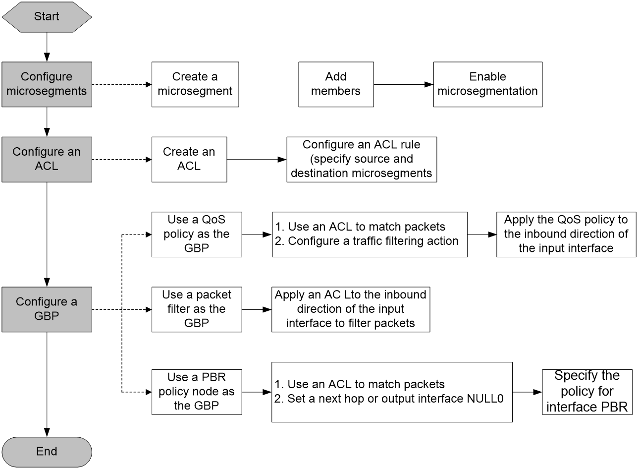
As shown in Figure 1, the microsegmentation feature contains the microsegment, ACL, and GBP settings. A GBP can be a QoS policy, a packet filter, or a PBR policy node.
This feature controls whether members in different microsegments can communicate. The GBP takes effect on the local end of a link. To control bidirectional traffic, configure this feature on both ends. Intermediate nodes do not require the configuration of this feature.
This feature can be used in IP and VXLAN networks. In an IP network, all settings must be configured on the Layer 3 gateway devices. In a VXLAN network, all settings must be configured on the VTEPs.
Figure 1 Microsegmentation configuration workflow
How microsegmentation works
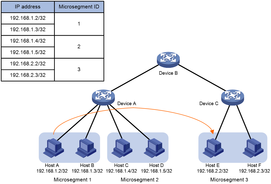
The microsegmentation feature works in the same way in IP and VXLAN networks. As shown in Figure 2, this section takes unidirectional traffic in an IP network as an example to illustrate how this feature works. This example uses a QoS policy as the GBP.
1. After receiving a packet sent from Host A to Host D, Device A obtains its source IP address (192.168.1.2) and destination IP address (192.168.1.5).
2. Device A searches the FIB table for the source IP address according to the longest match rule and determines that Host A belongs to microsegment 1.
3. Device A searches the FIB table for the destination IP address according to the longest match rule and determines that Host B belongs to microsegment 2.
4. Device A matches microsegment 1 and microsegment 2 against ACLs and executes one of the following actions in the QoS policy on matching packets:
¡ Forwards matching packets if the action is filter permit.
¡ Drops matching packets if the action is filter deny.
Figure 2 Forwarding of Layer 3 packets in an IP network
The microsegmentation feature works in the same way for cross-device packet forwarding.
Restrictions and guidelines: Microsegmentation configuration
· Configure this feature at the early stage of network deployment. Otherwise, this feature might fail to work because a large number of routes exist.
· This feature does not take effect in an EVPN network.
· If Layer 3-related proxy functions, such as ARP proxy and ND proxy are configured, this feature does not take effect.
· This feature does not take effect on a port operating as the customer-side port.
· This feature does not take effect for gateway IP addresses.
· In terms of VLANs, this feature is supported only for common VLANs.
· This feature does not take effect on outgoing traffic matching an ACL.
· After you apply this feature to the default route, the apply default-next-hop command configuration does not take effect.
When you use this feature to control unidirectional inter-VPN traffic, follow these restrictions and guidelines:
· On the source PE device, if the route guiding traffic forwarding is a network route, you must add the destination address of the route to a microsegment as a member.
· On the destination PE device, if the route is a host route, you must add the destination address of the route to a microsegment as a member.
Microsegmentation tasks at a glance
To configure microsegmentation, perform the following tasks:
· Configure a GBP. Choose one option as needed:
¡ Configuring packet filtering
Prerequisites for microsegmentation configuration
This feature can be used in IP and VXLAN For information about configuring these features, see the relevant configuration guides.
Configuring a microsegment
Restrictions and guidelines
To control bidirectional traffic in an IP or VXLAN network, you must configure the same microsegment on the two ends.
Procedure
1. Enter system view.
system-view
2. Create a microsegment and enter microsegment view.
microsegment microsegment-id [ name microsegment-name ]
3. Add a member to the microsegment.
member ipv4 ipv4-address { mask | mask-length } [ vpn-instance vpn-instance-name ]
member ipv6 ipv6-address prefix-length [ vpn-instance vpn-instance-name ]
By default, a microsegment does not contain members.
4. Return to system view.
quit
5. Enable microsegmentation.
microsegment enable
By default, microsegmentation is disabled.
Configuring an ACL
Restrictions and guidelines
To control bidirectional traffic, you must configure an ACL on both ends and configure an ACL rule with swapped source and destination microsegments on the two ends.
If you use a PBR policy node or a QoS policy as the GBP, the ACL rules must be permit rules. The apply action or QoS action is taken on matching packets.
If you use a packet filter as the GBP, the ACL rules can be permit or deny rules. Matching packets are permitted or denied.
Procedure
1. Enter system view.
system-view
2. Create an IPv4 or IPv6 advanced ACL and enter its view. Choose one option as needed:
¡ acl [ ipv6 ] number acl-number [ name acl-name ] [ match-order { auto | config } ]
¡ acl [ ipv6 ] { advanced | basic } { acl-number | name acl-name } [ match-order { auto | config } ]
3. Configure a rule.
For more information, see the rule command in ACL and QoS Command Reference.
In the rule command, the destination microsegment microsegment-id and source microsegment microsegment-id options must be specified, and other parameters can be configured as needed.
Configuring a GBP
Configuring PBR
About this task
You can control communication between microsegments by referencing an ACL and specifying a next hop (permitting traffic) or the output interface NULL0 (dropping traffic) in a PBR policy.
For more information about PBR, see Layer 3—IP Routing Configuration Guide.
Restrictions and guidelines
To control bidirectional traffic, you must configure PBR on both ends.
Procedure
1. Enter system view.
system-view
2. Create a node for a policy, and enter its view.
policy-based-route policy-name [ deny | permit ] node node-number
3. Set an ACL match criterion for the node.
if-match acl { acl-number | name acl-name }
By default, no ACL match criterion is set.
4. Configure an action for the node. Choose one option as needed:
¡ Set a next hop.
apply next-hop ip-address
¡ Set NULL0 as the output interface.
apply output-interface null0
By default, no action is configured.
5. Return to system view.
quit
6. Specify the policy for interface PBR.
ip policy-based-route policy-name
By default, no interface policy is applied to an interface.
Configuring a QoS policy
About this task
You can use the traffic filtering action in a QoS policy to control communication between microsegments.
Procedure
1. Enter system view.
system-view
2. Define a traffic class.
a. Create a traffic class and enter traffic class view.
traffic classifier classifier-name [ operator { and | or } ]
b. Configure a match criterion.
if-match acl [ ipv6 ] { acl-number | name acl-name }
By default, no match criterion is configured.
Only IPv4 and IPv6 advanced ACLs can be used to match packets.
c. Return to system view.
quit
3. Define a traffic behavior.
a. Create a traffic behavior and enter traffic behavior view.
traffic behavior behavior-name
b. Configure a traffic filtering action.
filter { deny | permit }
By default, no traffic filtering action is configured.
c. Return to system view.
quit
4. Define a QoS policy.
a. Create a QoS policy and enter QoS policy view.
qos policy policy-name
b. Associate the traffic class with the traffic behavior in the QoS policy.
classifier classifier-name behavior behavior-name
By default, a traffic class is not associated with a traffic behavior.
c. Return to system view.
quit
5. Apply the QoS policy to an interface.
a. Enter interface view.
interface interface-type interface-number
b. Apply the QoS policy to the inbound direction of the interface.
qos apply policy policy-name inbound
By default, no QoS policy is applied to an interface.
Configuring packet filtering
About this task
You can apply an ACL to the inbound direction of an interface to control communication between microsegments.
Procedure
6. Enter system view.
system-view
7. Enter interface view.
interface interface-type interface-number
8. Apply an ACL to the inbound direction of the interface.
packet-filter [ ipv6 ] { acl-number | name acl-name } inbound
By default, no ACL is applied to an interface.
Display and maintenance commands for microsegmentation
Execute display commands in any view.
|
Task |
Command |
|
Display microsegment configuration. |
display microsegment [ microsegment-id | name microsegment-name ] |
