- Table of Contents
- Related Documents
-
| Title | Size | Download |
|---|---|---|
| 04-Data buffer configuration | 98.31 KB |
Contents
Cell resources and packet resources
Configuring data buffer alarms
Restrictions and guidelines for data buffer alarm configuration
Configuring alarm thresholds for the ingress or egress buffer
Configuring alarm thresholds for the Headroom buffer
Configuring packet-drop alarms
Configuring data buffers
About data buffers
Data buffer types
Data buffers temporarily store packets to avoid packet loss.
The following data buffers are available:
· Ingress buffer—Stores incoming packets when the CPU is busy.
· Egress buffer—Stores outgoing packets when network congestion occurs.
Figure 1 shows the structure of ingress and egress buffers.
Figure 1 Data buffer structure

Cell resources and packet resources
A buffer uses the following types of resources:
· Cell resources—Store packets. The buffer uses cell resources based on packet sizes. Suppose a cell resource provides 208 bytes. The buffer allocates one cell resource to a 128-byte packet and two cell resources to a 300-byte packet.
· Packet resources—Store packet pointers. A packet pointer indicates where the packet is located in cell resources. The buffer uses one packet resource for each incoming or outgoing packet.
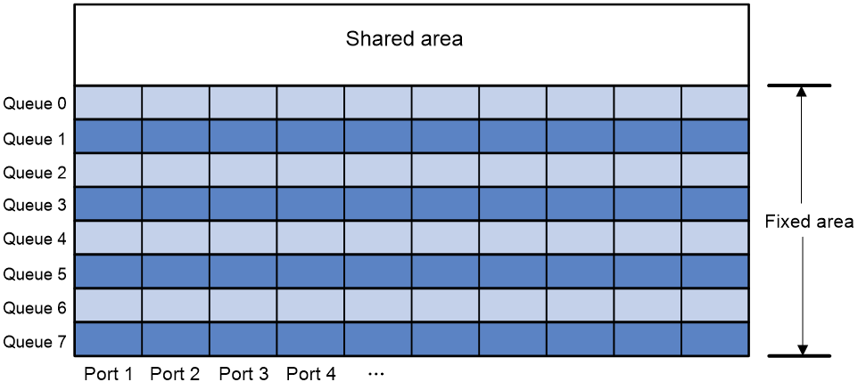
Fixed area and shared area
Each type of resources has a fixed area and a shared area.
· Fixed area—Partitioned into queues, each of which is equally divided by all the interfaces on the switch, as shown in Figure 2. When congestion occurs or the CPU is busy, the following rules apply:
a. An interface first uses the relevant queues of the fixed area to store packets.
b. When a queue is full, the interface uses the corresponding queue of the shared area.
c. When the queue in the shared area is also full, the interface discards subsequent packets.
The system allocates the fixed area among queues as specified by the user. Even if a queue is not full, other queues cannot preempt its space. Similarly, the share of a queue for an interface cannot be preempted by other interfaces even if it is not full.
· Shared area—Partitioned into queues, each of which is not equally divided by the interfaces, as shown in Figure 2. The system determines the actual shared-area space for each queue according to user configuration and the number of packets actually received and sent. If a queue is not full, other queues can preempt its space.
The system puts packets received or sent on all interfaces into a queue in the order they arrive. When the queue is full, subsequent packets are dropped.
Figure 2 Fixed area and shared area
Data buffer tasks at a glance
To configure the data buffer, perform the following tasks:
· (Optional.) Configuring data buffer alarms
¡ Configuring alarm thresholds for the ingress or egress buffer
¡ Configuring alarm thresholds for the Headroom buffer
¡ Configuring packet-drop alarms
Enabling the Burst feature
About this task
The Burst feature enables the device to automatically allocate cell and packet resources. It is well suited to the following scenarios:
· Broadcast or multicast traffic is intensive, resulting in bursts of traffic.
· Traffic comes in and goes out in one of the following ways:
¡ Enters a device from a high-speed interface and goes out of a low-speed interface.
¡ Enters from multiple same-rate interfaces at the same time and goes out of an interface with the same rate.
Procedure
1. Enter system view.
system-view
2. Enable the Burst feature.
In standalone mode:
burst-mode enable
By default, the Burst feature is disabled.
Configuring data buffer alarms
About data buffer alarms
This feature works with a network management system (such as IMC). Data buffer alarms include threshold-crossing alarms and packet drop alarms. The device reports these alarms to the network management system for displaying the data buffer usage.
Restrictions and guidelines for data buffer alarm configuration
If you configure alarm thresholds after you configure the PFC, generic flow control, or Burst feature, you must reconfigure the alarm thresholds. For more information about PFC and generic flow control, see Ethernet interface configuration in Interface Configuration Guide.
Configuring alarm thresholds for the ingress or egress buffer
1. Enter system view.
system-view
2. Configure the alarm thresholds. Choose the options to configure as needed:
¡ Configure the global alarm threshold for a queue.
In standalone mode:
buffer { egress | ingress } usage threshold slot slot-number queue queue-id ratio ratio
In IRF mode:
buffer { egress | ingress } usage threshold chassis chassis-number slot slot-number queue queue-id ratio ratio
The default setting is 100%.
¡ Execute the following commands in sequence to configure the alarm threshold for a queue on an interface:
interface interface-type interface-number
buffer { egress | ingress } usage threshold queue queue-id ratio ratio
By default, an interface uses the global alarm threshold. In this case, the display this [ all ] command does not display the global alarm threshold that the interface uses when it is executed in interface view. For this command to display the alarm threshold that the interface uses, configure the alarm threshold as the default value and or a non-default value in interface view.
3. Enable threshold-crossing alarms.
buffer threshold alarm { egress | ingress } enable
By default, threshold-crossing alarms are disabled.
4. (Optional.) Set the interval for sending threshold-crossing alarms.
buffer threshold alarm { egress | ingress } interval interval
The default setting is 5 seconds.
Configuring alarm thresholds for the Headroom buffer
1. Enter system view.
system-view
2. Configure the alarm thresholds. Choose the options to configure as needed:
¡ Configure the global per-queue alarm threshold.
In standalone mode:
buffer usage threshold headroom slot slot-number ratio ratio
In IRF mode:
buffer usage threshold headroom chassis chassis-number slot slot-number ratio ratio
The default setting is 100%.
¡ Execute the following commands in sequence to configure the alarm threshold for a queue on an interface:
interface interface-type interface-number
buffer usage threshold headroom queue queue-id ratio ratio
By default, an interface uses the global per-queue alarm threshold. In this case, the display this [ all ] command does not display the global per-queue alarm threshold that the interface uses when it is executed in interface view. For this command to display the per-queue alarm threshold that the interface uses, configure the per-queue alarm threshold as the default value and or a non-default value in interface view.
3. Enable threshold-crossing alarms.
buffer threshold alarm headroom enable
By default, threshold-crossing alarms are disabled.
4. (Optional.) Set the interval for sending threshold-crossing alarms.
buffer threshold alarm headroom interval interval
The default setting is 5 seconds.
Configuring packet-drop alarms
About this task
This feature allows the device to periodically send packet-drop information to the NMS.
Restrictions and guidelines
This feature does not take effect on the Headroom buffer.
Procedure
1. Enter system view.
system-view
2. Enable packet-drop alarms.
buffer packet-drop alarm enable
By default, packet-drop alarms are disabled.
3. (Optional.) Set the interval for sending packet-drop alarms.
buffer packet-drop alarm interval interval
The default setting is 5 seconds.
