- Table of Contents
- Related Documents
-
| Title | Size | Download |
|---|---|---|
| 01-H3C_IRF_Configuration_Examples | 186.92 KB |
|
|
|
H3C IRF Configuration Examples |
|
|
|
|
|
|
Software version: Release 7595
Document version: 6W100-20201031
Copyright © 2020 New H3C Technologies Co., Ltd. All rights reserved.
No part of this manual may be reproduced or transmitted in any form or by any means without prior written consent of New H3C Technologies Co., Ltd.
Except for the trademarks of New H3C Technologies Co., Ltd., any trademarks that may be mentioned in this document are the property of their respective owners.
The information in this document is subject to change without notice.
Contents
General restrictions and guidelines
Hardware compatibility with IRF
Bridge MAC restrictions for IRF member devices
Candidate IRF physical interfaces
IRF physical interface configuration restrictions and guidelines
Feature compatibility and configuration restrictions
MAD configuration restrictions
Example: Setting up a LACP MAD-enabled two-chassis IRF fabric
Verifying the link backup function of multichassis aggregations
Verifying the link backup function of IRF connections
Introduction
This document provides examples for deploying two-chassis IRF fabrics and four-chassis IRF fabrics.
Prerequisites
The configuration examples in this document were created and verified in a lab environment, and all the devices were started with the factory default configuration. When you are working on a live network, make sure you understand the potential impact of every command on your network.
This document assumes that you have basic knowledge of H3C IRF.
General restrictions and guidelines
When you set up and configure an IRF fabric, follow the restrictions and guidelines in this section.
Hardware compatibility with IRF
An H3C S12500G-AF switch can form an IRF fabric only with devices in the same series.
All member devices in an IRF fabric must use the same type of MPUs.
Software requirements for IRF
All IRF member devices must run the same software image version. Make sure the software auto-update feature is enabled on all member devices.
IRF fabric size
An S12500G-AF IRF fabric supports a maximum of two chassis.
Bridge MAC restrictions for IRF member devices
Each member device must have a unique bridge MAC address. IRF setup fails if any two member devices have the same bridge MAC address.
Candidate IRF physical interfaces
Use the following physical interfaces for IRF links:
· 10-GE fiber ports.
· 40-GE fiber ports.
· 100-GE fiber ports.
IRF port connection
When you connect neighboring IRF members, connect the physical interfaces of IRF-port 1 on one member to the physical interfaces of IRF-port 2 on the other (see Figure 1). On neighboring members, IRF ports with the same port index cannot have physical connections.
Figure 1 Connecting IRF physical interfaces
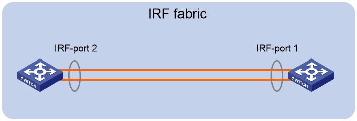
To use the ring topology, you must have a minimum of three member devices.
IRF physical interface configuration restrictions and guidelines
Grouped port binding restrictions
You can use 40-GE ports for IRF links, or use 10-GE breakout interfaces of a 40-GE port for IRF links. To split a 40-GE port, use the using tengige command.
When you use the 10-GE breakout interfaces of a 40-GE port for IRF links, follow these restrictions and guidelines:
· If you use one breakout interface as an IRF physical interface, all remaining breakout interfaces can only act as IRF physical interfaces. To use a breakout interface for any purposes other than IRF physical interfaces, do not bind any of the breakout interfaces to an IRF port.
· You can bind the breakout interfaces to the same or different IRF ports.
· Before you bind one breakout interface to an IRF port, shut down all the breakout interfaces that have not been bound to IRF ports. If any one of the unbound breakout interfaces is in up state, the bind action will fail.
· Before you remove one breakout interface from an IRF port, you must shut down all the breakout interfaces. If any one of the breakout interfaces is in up state, the remove action will fail.
· Bring up all the breakout interfaces after you bind them to an IRF port. If any one of the breakout interfaces is not bound to an IRF port, you cannot bring up any breakout interfaces.
Command configuration restrictions
On a physical interface bound to an IRF port, you can execute only the following commands:
· Basic interface commands, including shutdown and description. For more information about these commands, see Ethernet interface commands in Interface Command Reference.
· The flow-interval command, which sets the statistics polling interval on an interface. For more information about this command, see Ethernet interface commands in Interface Command Reference.
· PFC commands, including the priority-flow-control and priority-flow-control no-drop dot1p commands. For more information about these commands, see Ethernet interface commands in Interface Command Reference.
· The port link-flap protect enable command, which enables link flapping protection on an interface. To prevent IRF link flapping from affecting system performance, link flapping protection acts differently on IRF physical interfaces than on common network interfaces, as follows:
¡ Link flapping protection is enabled by default on IRF physical interfaces. This feature takes effect on an IRF physical interface as long as it is enabled on that interface, regardless of whether link flapping protection has been enabled globally.
¡ If the number of link flappings on an IRF physical interface crosses the link flapping threshold during a flapping detection interval, the system displays an event message. However, the system does not shut down that IRF physical interface as it would do with a common network interface.
For more information about this command, see Ethernet interface commands in Interface Command Reference.
· MAC address table configuration commands, including the mac-address static source-check enable command. In a VXLAN or EVPN network, to ensure successful forwarding of Layer 3 traffic across member devices, use the undo mac-address static source-check enable command on each IRF physical interface. For information about this command, see MAC address table configuration in Layer 2—LAN Switching Command Reference.
· LLDP commands, including:
¡ lldp admin-status.
¡ lldp check-change-interval.
¡ lldp enable.
¡ lldp encapsulation snap.
¡ lldp notification remote-change enable.
¡ lldp tlv-enable.
For more information about these commands, see Layer 2—LAN Switching Command Reference.
· The port service-loopback group command, which assigns the physical interface to a service loopback group. For more information about this command, see Layer 2—LAN Switching Command Reference.
|
|
IMPORTANT: Do not execute the port service-loopback group command on an IRF physical interface if that interface is the only member interface of an IRF port. Doing so will split the IRF fabric, because this command also removes the binding of the physical interface and IRF port. |
· The mirroring-group reflector-port command, which specifies the physical interface as a reflector port for remote mirroring. For more information about this command, see port mirroring in Network Management and Monitoring Command Reference.
|
|
IMPORTANT: Do not execute the mirroring-group reflector-port command on an IRF physical interface if that interface is the only member interface of an IRF port. Doing so will split the IRF fabric, because this command also removes the binding of the physical interface and IRF port. |
Feature compatibility and configuration restrictions
ECMP
To form an IRF fabric, all member devices in the IRF fabric must support the same maximum number of ECMP routes. For more information about ECMP, see Layer 3—IP Routing Configuration Guide.
System operating mode
All member devices in the IRF fabric must work in the same system operating mode (set by using the system-working-mode command). For more information about the system operating mode, see Fundamentals Configuration Guide.
MAD configuration restrictions
You can configure a minimum of one MAD mechanism on an IRF fabric for prompt IRF split detection.
· Do not configure LACP MAD together with ARP MAD or ND MAD, because they handle collisions differently.
· Do not configure BFD MAD together with ARP MAD or ND MAD. BFD MAD is mutually exclusive with the spanning tree feature. ARP MAD and ND MAD require the spanning tree feature.
Licensing requirements
For a license-based feature to run correctly on an IRF fabric, make sure the licenses installed for the feature on all member devices are the same. For more information about feature licensing, see Fundamentals Configuration Guide.
Example: Setting up a LACP MAD-enabled two-chassis IRF fabric
Network configuration
As shown in Figure 2:
· Set up a two-chassis IRF fabric at the core layer of the network.
· Use multichassis link aggregations to connect the IRF fabric to the access switches and the upstream egress routers.
· Use LACP MAD to detect IRF split.
· Run OSPF between the IRF fabric and the egress routers.
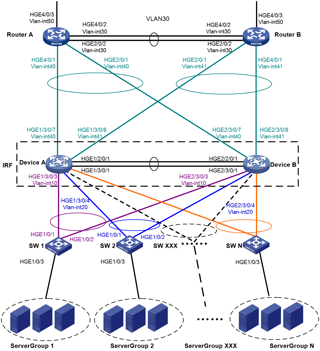
Table 1 VLAN and IP address assignment
|
Device |
VLAN interface |
IP address |
|
Router A |
VLAN-interface 30 |
172.24.2.2/24 |
|
Router A |
VLAN-interface 40 |
172.24.40.2/24 |
|
Router A |
VLAN-interface 50 |
172.24.1.2/24 |
|
Router B |
VLAN-interface 30 |
172.24.2.3/24 |
|
Router B |
VLAN-interface 41 |
172.24.41.3/24 |
|
Router B |
VLAN-interface 50 |
172.24.4.3/24 |
|
IRF fabric |
VLAN-interface 10 |
172.24.10.254/24 |
|
IRF fabric |
VLAN-interface 20 |
172.24.20.254/24 |
|
IRF fabric |
VLAN-interface 40 |
172.24.40.254/24 |
|
IRF fabric |
VLAN-interface 41 |
172.24.41.254/24 |
Restrictions and guidelines
For LACP MAD to run correctly, ensure that the intermediate device supports extended LACPDUs for LACP MAD.
To avoid single points of failure, use multichassis link aggregations to connect the IRF fabric to the downstream and upstream devices.
You do not need to run LACP MAD on all link aggregations. You can detect IRF split effectively by running LACP MAD on one dynamic link aggregation.
When you configure LACP MAD on a link aggregation, follow these restrictions and guidelines:
· The link aggregation must use dynamic aggregation mode.
· The link aggregation must have a minimum of one member link from each member chassis.
· If the intermediate device is also an IRF fabric, you must assign the two IRF fabrics different domain IDs for correct split detection.
Procedures
Setting up the IRF fabric
1. Configure Device A:
# Assign member ID 1 to Device A.
<DeviceA> system-view
[DeviceA] irf member 1
# Bind HundredGigE 2/0/1 and HundredGigE 3/0/1 to IRF-port 2.
[DeviceA] irf-port 2
[DeviceA-irf-port2] port group interface hundredgige 2/0/1
[DeviceA-irf-port2] port group interface hundredgige 3/0/1
[DeviceA-irf-port2] quit
# Save the running configuration to the main next-startup configuration file before changing the operating mode to IRF.
|
|
IMPORTANT: The mode change requires a system reboot. The save operation prevents loss of unsaved settings on reboot. |
[DeviceA] save
# Enable IRF mode.
[DeviceA] chassis convert mode irf
The device will switch to IRF mode and reboot. Continue? [Y/N]:y
You are recommended to save the current running configuration and specify the configuration file for the next startup. Continue? [Y/N]:y
Do you want to convert the content of the next startup configuration file cfa0:/
irf.cfg to make it available in stack mode? [Y/N]:y
Now rebooting, please wait...
2. Configure Device B:
# Assign member ID 2 to Device B.
<DeviceB> system-view
[DeviceB] irf member 2
# Bind HundredGigE 2/0/1 and HundredGigE 3/0/1 to IRF-port 1.
[DeviceB] irf-port 1
[DeviceB-irf-port1] port group interface hundredgige 2/0/1
[DeviceB-irf-port1] port group interface hundredgige 3/0/1
[DeviceB-irf-port1] quit
# Save the configuration.
[DeviceB] save
# Connect IRF-port 2 on Device A to IRF-port 1 on Device B, as shown in Figure 2.
# Enable IRF mode.
[DeviceB] chassis convert mode irf
The device will switch to IRF mode and reboot. Continue? [Y/N]:y
You are recommended to save the current running configuration and specify the configuration file for the next startup. Continue? [Y/N]:y
Do you want to convert the content of the next startup configuration file cfa0:/
irf.cfg to make it available in stack mode? [Y/N]:y
Now rebooting, please wait...
Configuring software features
This example provides only basic software settings.
Configuring the IRF fabric
After the IRF fabric is formed, the master's system name becomes the fabric's system name. You can configure software features on the fabric as you do on a standalone device.
1. Configure link aggregations:
# Create a Layer 2 dynamic aggregate interface Bridge-Aggregation 1. Enable LACP MAD on the aggregate interface.
<DeviceA> system-view
[DeviceA] interface bridge-aggregation 1
[DeviceA-Bridge-Aggregation1] link-aggregation mode dynamic
[DeviceA-Bridge-Aggregation1] mad enable
You need to assign a domain ID (range: 0-4294967295)
[Current domain is: 0]:
The assigned domain ID is: 0
[DeviceA-Bridge-Aggregation1] quit
# Assign the downlink ports connected to SW 1 to the aggregation group of Bridge-Aggregation 1.
[DeviceA] interface hundredgige 1/3/0/3
[DeviceA-HundredGigE1/3/0/3] port link-aggregation group 1
[DeviceA-HundredGigE1/3/0/3] quit
[DeviceA] interface hundredgige 2/3/0/3
[DeviceA-HundredGigE2/3/0/3] port link-aggregation group 1
[DeviceA-HundredGigE2/3/0/3] quit
# Create Bridge-Aggregation 2. Assign the downlink ports connected to SW 2 to the aggregation group.
[DeviceA] interface bridge-aggregation 2
[DeviceA-Bridge-Aggregation2] quit
[DeviceA] interface hundredgige 1/3/0/4
[DeviceA-HundredGigE1/3/0/4] port link-aggregation group 2
[DeviceA-HundredGigE1/3/0/4] quit
[DeviceA] interface hundredgige 2/3/0/4
[DeviceA-HundredGigE2/3/0/4] port link-aggregation group 2
[DeviceA-HundredGigE2/3/0/4] quit
# Create Bridge-Aggregation 1023. Assign the uplink ports connected to Router A to Bridge-Aggregation 1023.
[DeviceA] interface bridge-aggregation 1023
[DeviceA-Bridge-Aggregation1023] quit
[DeviceA] interface hundredgige 1/3/0/7
[DeviceA-HundredGigE1/3/0/7] port link-aggregation group 1023
[DeviceA-HundredGigE1/3/0/7] quit
[DeviceA] interface hundredgige 2/3/0/7
[DeviceA-HundredGigE2/3/0/7] port link-aggregation group 1023
[DeviceA-HundredGigE2/3/0/7] quit
# Create Bridge-Aggregation 1024. Assign the uplink ports connected to Router B to Bridge-Aggregation 1024.
[DeviceA] interface bridge-aggregation 1024
[DeviceA-Bridge-Aggregation1024] quit
[DeviceA] interface hundredgige 1/3/0/8
[DeviceA-HundredGigE1/3/0/8] port link-aggregation group 1024
[DeviceA-HundredGigE1/3/0/8] quit
[DeviceA] interface hundredgige 2/3/0/8
[DeviceA-HundredGigE2/3/0/8] port link-aggregation group 1024
[DeviceA-HundredGigE2/3/0/8] quit
2. Configure VLANs, ports, and IP addresses:
# Create VLAN 10, assign an IP address to VLAN-interface 10, and assign Bridge-Aggregation 1 to VLAN 10.
[DeviceA] vlan 10
[DeviceA-vlan10] quit
[DeviceA] interface vlan-interface 10
[DeviceA-Vlan-interface10] ip address 172.24.10.254 24
[DeviceA-Vlan-interface10] quit
[DeviceA] interface bridge-aggregation 1
[DeviceA-Bridge-Aggregation1] port link-type trunk
[DeviceA-Bridge-Aggregation1] undo port trunk permit vlan 1
[DeviceA-Bridge-Aggregation1] port trunk permit vlan 10
[DeviceA-Bridge-Aggregation1] quit
# Create VLAN 20, assign an IP address to VLAN-interface 20, and assign Bridge-Aggregation 2 to VLAN 20.
[DeviceA] vlan 20
[DeviceA-vlan20] quit
[DeviceA] interface vlan-interface 20
[DeviceA-Vlan-interface20] ip address 172.24.20.254 24
[DeviceA-Vlan-interface20] quit
[DeviceA] interface bridge-aggregation 2
[DeviceA-Bridge-Aggregation2] port link-type trunk
[DeviceA-Bridge-Aggregation2] undo port trunk permit vlan 1
[DeviceA-Bridge-Aggregation2] port trunk permit vlan 20
[DeviceA-Bridge-Aggregation2] quit
# Create VLAN 40, assign an IP address to VLAN-interface 40, and assign Bridge-Aggregation 1023 to VLAN 40.
[DeviceA] vlan 40
[DeviceA-vlan40] quit
[DeviceA] interface vlan-interface 40
[DeviceA-Vlan-interface40] ip address 172.24.40.254 24
[DeviceA-Vlan-interface40] quit
[DeviceA] interface bridge-aggregation 1023
[DeviceA-Bridge-Aggregation1023] port access vlan 40
[DeviceA-Bridge-Aggregation1023] quit
# Create VLAN 41, assign an IP address to VLAN-interface 41, and assign Bridge-Aggregation 1024 to VLAN 41.
[DeviceA] vlan 41
[DeviceA-vlan41] quit
[DeviceA] interface vlan-interface 41
[DeviceA-Vlan-interface41] ip address 172.24.41.254 24
[DeviceA-Vlan-interface41] quit
[DeviceA] interface bridge-aggregation 1024
[DeviceA-Bridge-Aggregation1024] port access vlan 41
[DeviceA-Bridge-Aggregation1024] quit
3. Configure OSPF between the IRF fabric and the egress routers.
[DeviceA] ospf
[DeviceA-ospf-1] import-route direct
[DeviceA-ospf-1] area 0
[DeviceA-ospf-1-area-0.0.0.0] network 172.24.40.0 0.0.0.255
[DeviceA-ospf-1-area-0.0.0.0] network 172.24.41.0 0.0.0.255
[DeviceA-ospf-1-area-0.0.0.0] quit
[DeviceA-ospf-1] quit
Configuring SW 1
1. Configure a link aggregation:
# Create Bridge-Aggregation 1 and enable the dynamic aggregation mode. You must enable the dynamic aggregation mode because this link aggregation will be used for LACP MAD.
<SW1> system-view
[SW1] interface bridge-aggregation 1
[SW1-Bridge-Aggregation1] link-aggregation mode dynamic
[SW1-Bridge-Aggregation1] quit
# Assign the uplink ports connected to the IRF fabric to Bridge-Aggregation 1.
[SW1] interface hundredgige 1/0/1
[SW1-HundredGigE1/0/1] port link-aggregation group 1
[SW1-HundredGigE1/0/1] quit
[SW1] interface hundredgige 1/0/2
[SW1-HundredGigE1/0/2] port link-aggregation group 1
[SW1-HundredGigE1/0/2] quit
2. Configure VLANs, ports, and IP addresses:
# Create all VLANs.
[SW1] vlan all
# Configure VLAN settings on the uplink aggregate interface connected to the IRF fabric.
[SW1] interface bridge-aggregation 1
[SW1-Bridge-Aggregation1] port link-type trunk
[SW1-Bridge-Aggregation1] undo port trunk permit vlan 1
[SW1-Bridge-Aggregation1] port trunk permit vlan 10
[SW1-Bridge-Aggregation1] quit
# Configure VLAN settings on the port connected to Server Group 1.
[SW1] interface hundredgige 1/0/3
[SW1-HundredGigE1/0/3] port link-type trunk
[SW1-HundredGigE1/0/3] port trunk permit vlan all
[SW1-HundredGigE1/0/3] undo port trunk permit vlan 1
[SW1-HundredGigE1/0/3] quit
Configuring SW 2
1. Configure a link aggregation:
# Create Bridge-Aggregation 1.
<SW2> system-view
[SW2] interface bridge-aggregation 1
[SW2-Bridge-Aggregation1] quit
# Assign the uplink ports connected to the IRF fabric to Bridge-Aggregation 1.
[SW2] interface hundredgige 1/0/1
[SW2-HundredGigE1/0/1] port link-aggregation group 1
[SW2-HundredGigE1/0/1] quit
[SW2] interface hundredgige 1/0/2
[SW2-HundredGigE1/0/2] port link-aggregation group 1
[SW2-HundredGigE1/0/2] quit
2. Configure VLANs, ports, and IP addresses:
# Create all VLANs.
[SW2] vlan all
# Configure VLAN settings on the uplink aggregate interface connected to the IRF fabric.
[SW2] interface bridge-aggregation 1
[SW2-Bridge-Aggregation1] port link-type trunk
[SW2-Bridge-Aggregation1] undo port trunk permit vlan 1
[SW2-Bridge-Aggregation1] port trunk permit vlan 20
[SW2-Bridge-Aggregation1] quit
# Configure VLAN settings on the port connected to Server Group 2.
[SW2] interface hundredgige 1/0/3
[SW2-HundredGigE1/0/3] port link-type trunk
[SW2-HundredGigE1/0/3] port trunk permit vlan all
[SW2-HundredGigE1/0/3] undo port trunk permit vlan 1
[SW2-HundredGigE1/0/3] quit
Configuring Router A
In this example, the egress router configuration only includes the connection to the IRF fabric.
1. Configure link aggregations:
# Create Bridge-Aggregation 1. Assign the downlink ports connected to the IRF fabric to Bridge-Aggregation 1.
<RouterA> system-view
[RouterA] interface bridge-aggregation 1
[RouterA-Bridge-Aggregation1] quit
[RouterA] interface hundredgige 4/0/1
[RouterA-HundredGigE4/0/1] port link-mode bridge
[RouterA-HundredGigE4/0/1] port link-aggregation group 1
[RouterA-HundredGigE4/0/1] quit
[RouterA] interface hundredgige 2/0/1
[RouterA-HundredGigE2/0/1] port link-mode bridge
[RouterA-HundredGigE2/0/1] port link-aggregation group 1
[RouterA-HundredGigE2/0/1] quit
# Create Bridge-Aggregation 2. Assign the ports connected to Router B to Bridge-Aggregation 2.
[RouterA] interface bridge-aggregation 2
[RouterA-Bridge-Aggregation2] quit
[RouterA] interface hundredgige 4/0/2
[RouterA-HundredGigE4/0/2] port link-mode bridge
[RouterA-HundredGigE4/0/2] port link-aggregation group 2
[RouterA-HundredGigE4/0/2] quit
[RouterA] interface hundredgige 2/0/2
[RouterA-HundredGigE2/0/2] port link-mode bridge
[RouterA-HundredGigE2/0/2] port link-aggregation group 2
[RouterA-HundredGigE2/0/2] quit
2. Configure VLANs, ports, and IP addresses:
# Create VLAN 40, assign an IP address to VLAN-interface 40, and assign Bridge-Aggregation 1 to VLAN 40.
[RouterA] vlan 40
[RouterA-vlan40] quit
[RouterA] interface vlan-interface 40
[RouterA-vlan-interface40] ip address 172.24.40.2 24
[RouterA-vlan-interface40] quit
[RouterA] interface bridge-aggregation 1
[RouterA-Bridge-Aggregation1] port access vlan 40
[RouterA-Bridge-Aggregation1] quit
# Create VLAN 30, assign an IP address to VLAN-interface 30, and assign Bridge-Aggregation 2 to VLAN 30.
[RouterA] vlan 30
[RouterA-vlan30] quit
[RouterA] interface vlan-interface 30
[RouterA-vlan-interface30] ip address 172.24.2.2 24
[RouterA-vlan-interface30] quit
[RouterA] interface bridge-aggregation 2
[RouterA-Bridge-Aggregation2] port link-type access
[RouterA-Bridge-Aggregation2] port access vlan 30
[RouterA-Bridge-Aggregation2] quit
# Create VLAN 50, assign an IP address to VLAN-interface 50, and assign HundredGigE 4/0/3 to VLAN 50.
[RouterA] vlan 50
[RouterA-vlan50] quit
[RouterA] interface vlan-interface 50
[RouterA-vlan-interface50] ip address 172.24.1.2 24
[RouterA-vlan-interface50] quit
[RouterA] interface hundredgige 4/0/3
[RouterA-HundredGigE4/0/3] port link-mode bridge
[RouterA-HundredGigE4/0/3] port access vlan 50
[RouterA-HundredGigE4/0/3] quit
3. Configure OSPF between Router A and the IRF fabric.
[RouterA] ospf
[RouterA-ospf-1] import-route direct
[RouterA-ospf-1] area 0
[RouterA-ospf-1-area-0.0.0.0] network 172.24.40.0 0.0.0.255
[RouterA-ospf-1-area-0.0.0.0] network 172.24.2.0 0.0.0.255
[RouterA-ospf-1-area-0.0.0.0] quit
[RouterA-ospf-1] quit
Configuring Router B
In this example, the egress router configuration only includes the connection to the IRF fabric.
1. Configure link aggregations:
# Create Bridge-Aggregation 1. Assign the downlink ports connected to the IRF fabric to Bridge-Aggregation 1.
<RouterB> system-view
[RouterB] interface bridge-aggregation 1
[RouterB-Bridge-Aggregation1] quit
[RouterB] interface hundredgige 4/0/1
[RouterB-HundredGigE4/0/1] port link-mode bridge
[RouterB-HundredGigE4/0/1] port link-aggregation group 1
[RouterB-HundredGigE4/0/1] quit
[RouterB] interface hundredgige 2/0/1
[RouterB-HundredGigE2/0/1] port link-mode bridge
[RouterB-HundredGigE2/0/1] port link-aggregation group 1
[RouterB-HundredGigE2/0/1] quit
# Create Bridge-Aggregation 2. Assign the ports connected to Router A to Bridge-Aggregation 2.
[RouterB] interface bridge-aggregation 2
[RouterB-Bridge-Aggregation2] quit
[RouterB] interface hundredgige 4/0/2
[RouterB-HundredGigE4/0/2] port link-mode bridge
[RouterB-HundredGigE4/0/2] port link-aggregation group 2
[RouterB-HundredGigE4/0/2] quit
[RouterB] interface hundredgige 2/0/2
[RouterB-HundredGigE2/0/2] port link-mode bridge
[RouterB-HundredGigE2/0/2] port link-aggregation group 2
[RouterB-HundredGigE2/0/2] quit
2. Configure VLANs, ports, and IP addresses:
# Create VLAN 41, assign an IP address to VLAN-interface 41, and assign Bridge-Aggregation 1 to VLAN 41.
[RouterB] vlan 41
[RouterB-vlan41] quit
[RouterB] interface vlan-interface 41
[RouterB-vlan-interface41] ip address 172.24.41.3 24
[RouterB-vlan-interface41] quit
[RouterB] interface bridge-aggregation 1
[RouterB-Bridge-Aggregation1] port access vlan 41
[RouterB-Bridge-Aggregation1] quit
# Create VLAN 30, assign an IP address to VLAN-interface 30, and assign Bridge-Aggregation 2 to VLAN 30.
[RouterB] vlan 30
[RouterB-vlan30] quit
[RouterB] interface vlan-interface 30
[RouterB-vlan-interface30] ip address 172.24.2.3 24
[RouterB-vlan-interface30] quit
[RouterB] interface bridge-aggregation 2
[RouterB-Bridge-Aggregation2] port link-type access
[RouterB-Bridge-Aggregation2] port access vlan 30
[RouterB-Bridge-Aggregation2] quit
# Create VLAN 50, assign an IP address to VLAN-interface 50, and assign HundredGigE 4/0/3 to VLAN 50.
[RouterB] vlan 50
[RouterB-vlan50] quit
[RouterB] interface vlan-interface 50
[RouterB-vlan-interface50] ip address 172.24.4.3 24
[RouterB-vlan-interface50] quit
[RouterB] interface hundredgige 4/0/3
[RouterB-HundredGigE4/0/3] port link-mode bridge
[RouterB-HundredGigE4/0/3] port access vlan 50
[RouterB-HundredGigE4/0/3] quit
3. Configure OSPF between Router B and the IRF fabric.
[RouterB] ospf
[RouterB-ospf-1] import-route direct
[RouterB-ospf-1] area 0
[RouterB-ospf-1-area-0.0.0.0] network 172.24.41.0 0.0.0.255
[RouterB-ospf-1-area-0.0.0.0] network 172.24.2.0 0.0.0.255
[RouterB-ospf-1-area-0.0.0.0] quit
[RouterB-ospf-1] quit
Verifying the configuration
Verify that the IRF fabric, multichassis link aggregation configuration, and IRF link redundancy operate correctly.
Verifying the IRF function
# Execute the display irf command in any view.
[DeviceA] display irf
MemberID Slot Role Priority CPU-Mac Description
*+1 0 Master 1 0210-fc01-0000 ---
2 0 Standby 1 0210-fc02-0000 ---
--------------------------------------------------
* indicates the device is the master.
+ indicates the device through which the user logs in.
The Bridge MAC of the IRF is: 3822-d60f-2800
Auto upgrade : yes
Mac persistent : always
Domain ID : 0
Auto merge : yes
IRF mode : normal
The command output shows that the member chassis have formed an IRF fabric.
Verifying the link backup function of multichassis aggregations
# Shut down HundredGigE 1/3/0/8, the port connected to the egress router.
[DeviceA] interface hundredgige 1/3/0/8
[DeviceA-HundredGigE1/3/0/8] shutdown
# Ping an IP address on the public network from a PC in Server Group 1.
C:\Users>ping 202.108.22.5 -t
Pinging 202.108.22.5 with 32 bytes of data:
Reply from 202.108.22.5: bytes=32 time=1ms TTL=122
Reply from 202.108.22.5: bytes=32 time=13ms TTL=122
Reply from 202.108.22.5: bytes=32 time<1ms TTL=122
Request timed out.
Request timed out.
Request timed out.
Reply from 202.108.22.5: bytes=32 time<1ms TTL=122
Reply from 202.108.22.5: bytes=32 time<1ms TTL=122
Reply from 202.108.22.5: bytes=32 time<1ms TTL=122
The output shows that the address can be pinged after transient traffic disruption.
# Bring up HundredGigE 1/3/0/8 and shut down HundredGigE 2/3/0/8.
[DeviceA-HundredGigE1/3/0/8] undo shutdown
[DeviceA-HundredGigE1/3/0/8] quit
[DeviceA] interface hundredgige 2/3/0/8
[DeviceA-HundredGigE2/3/0/8] shutdown
# Ping the IP address on the public network from the PC.
C:\Users>ping 202.108.22.5 -t
Pinging 202.108.22.5 with 32 bytes of data:
Reply from 202.108.22.5: bytes=32 time=1ms TTL=122
Reply from 202.108.22.5: bytes=32 time=13ms TTL=122
Reply from 202.108.22.5: bytes=32 time<1ms TTL=122
Request timed out.
Request timed out.
Request timed out.
Reply from 202.108.22.5: bytes=32 time<1ms TTL=122
Reply from 202.108.22.5: bytes=32 time<1ms TTL=122
Reply from 202.108.22.5: bytes=32 time<1ms TTL=122
The output shows that the address can be pinged after transient traffic disruption.
Verifying the link backup function of IRF connections
Verify that the IRF fabric is integrated and can forward traffic across member chassis after one IRF connection cable is removed.
Configuration files
· IRF fabric:
#
irf mac-address persistent always
irf auto-update enable
irf auto-merge enable
undo irf link-delay
irf member 1 priority 1
irf member 2 priority 1
#
ospf 1
import-route direct
area 0.0.0.0
network 172.24.40.0 0.0.0.255
network 172.24.41.0 0.0.0.255
#
vlan 10
#
vlan 20
#
vlan 40
#
vlan 41
#
irf-port 1/2
port group interface HundredGigE1/2/0/1 mode enhanced
port group interface HundredGigE1/3/0/1 mode enhanced
#
irf-port 2/1
port group interface HundredGigE2/2/0/1 mode enhanced
port group interface HundredGigE2/3/0/1 mode enhanced
#
interface bridge-aggregation 1
port link-type trunk
undo port trunk permit vlan 1
port trunk permit vlan 10
link-aggregation mode dynamic
mad enable
#
interface bridge-aggregation 2
port link-type trunk
undo port trunk permit vlan 1
port trunk permit vlan 20
#
interface bridge-aggregation 1023
port access vlan 40
#
interface bridge-aggregation 1024
port access vlan 41
#
interface vlan-interface 10
ip address 172.24.10.254 255.255.255.0
#
interface vlan-interface 20
ip address 172.24.20.254 255.255.255.0
#
interface vlan-interface 40
ip address 172.24.40.254 255.255.255.0
#
interface HundredGigE 1/3/0/3
port link-mode bridge
port link-type trunk
undo port trunk permit vlan 1
port trunk permit vlan 10
port link-aggregation group 1
#
interface HundredGigE 1/3/0/4
port link-mode bridge
port link-type trunk
undo port trunk permit vlan 1
port trunk permit vlan 20
port link-aggregation group 2
#
interface HundredGigE 1/3/0/7
port link-mode bridge
port access vlan 40
port link-aggregation group 1023
#
interface HundredGigE 1/3/0/8
port link-mode bridge
port access vlan 41
port link-aggregation group 1024
#
interface HundredGigE 2/3/0/3
port link-mode bridge
port link-type trunk
undo port trunk permit vlan 1
port trunk permit vlan 10
port link-aggregation group 1
#
interface HundredGigE 2/3/0/4
port link-mode bridge
port link-type trunk
undo port trunk permit vlan 1
port trunk permit vlan 20
port link-aggregation group 2
#
interface HundredGigE 2/3/0/7
port link-mode bridge
port access vlan 40
port link-aggregation group 1023
#
interface HundredGigE 2/3/0/8
port link-mode bridge
port access vlan 41
port link-aggregation group 1024
#
· SW 1:
#
vlan 10
#
interface bridge-aggregation 1
port link-type trunk
undo port trunk permit vlan 1
port trunk permit vlan 10
link-aggregation mode dynamic
#
interface HundredGigE 1/0/1
port link-mode bridge
port link-type trunk
undo port trunk permit vlan 1
port trunk permit vlan 10
port link-aggregation group 1
#
interface HundredGigE 1/0/2
port link-mode bridge
port link-type trunk
undo port trunk permit vlan 1
port trunk permit vlan 10
port link-aggregation group 1
#
interface HundredGigE 1/0/3
port link-mode bridge
port link-type trunk
undo port trunk permit vlan 1
port trunk permit vlan 2 to 4094
#
· SW 2:
#
vlan 20
#
interface bridge-aggregation 1
port link-type trunk
undo port trunk permit vlan 1
port trunk permit vlan 20
#
interface HundredGigE 1/0/1
port link-mode bridge
port link-type trunk
undo port trunk permit vlan 1
port trunk permit vlan 20
port link-aggregation group 1
#
interface HundredGigE 1/0/2
port link-mode bridge
port link-type trunk
undo port trunk permit vlan 1
port trunk permit vlan 20
port link-aggregation group 1
#
interface HundredGigE 1/0/3
port link-mode bridge
port link-type trunk
undo port trunk permit vlan 1
port trunk permit vlan 2 to 4094
#
· Router A:
#
ospf 1
import-route direct
area 0.0.0.0
network 172.24.2.0 0.0.0.255
network 172.24.40.0 0.0.0.255
#
vlan 30
#
vlan 40
#
vlan 50
#
interface bridge-aggregation 1
port access vlan 40
#
interface bridge-aggregation 2
port access vlan 30
#
interface vlan-interface 30
ip address 172.24.2.2 255.255.255.0
#
interface vlan-interface 40
ip address 172.24.40.2 255.255.255.0
#
interface vlan-interface 50
ip address 172.24.1.2 255.255.255.0
#
interface HundredGigE 2/0/1
port link-mode bridge
port access vlan 40
port link-aggregation group 1
#
interface HundredGigE 2/0/2
port link-mode bridge
port access vlan 30
port link-aggregation group 2
#
interface HundredGigE 4/0/1
port link-mode bridge
port access vlan 40
port link-aggregation group 1
#
interface HundredGigE 4/0/2
port link-mode bridge
port access vlan 30
port link-aggregation group 2
#
interface HundredGigE 4/0/3
port link-mode bridge
port access vlan 50
#
· Router B:
#
ospf 1
import-route direct
area 0.0.0.0
network 172.24.2.0 0.0.0.255
network 172.24.41.0 0.0.0.255
#
vlan 30
#
vlan 41
#
vlan 50
#
interface bridge-aggregation 1
port access vlan 41
#
interface bridge-aggregation 2
port access vlan 30
#
interface vlan-interface 30
ip address 172.24.2.3 255.255.255.0
#
interface vlan-interface 41
ip address 172.24.41.3 255.255.255.0
#
interface vlan-interface 50
ip address 172.24.4.3 255.255.255.0
#
interface HundredGigE 2/0/1
port link-mode bridge
port access vlan 41
port link-aggregation group 1
#
interface HundredGigE 2/0/2
port link-mode bridge
port access vlan 30
port link-aggregation group 2
#
interface HundredGigE 4/0/1
port link-mode bridge
port access vlan 41
port link-aggregation group 1
#
interface HundredGigE 4/0/2
port link-mode bridge
port access vlan 30
port link-aggregation group 2
#
interface HundredGigE 4/0/3
port link-mode bridge
port access vlan 50
#
Related documentation
· H3C S12500G-AF Switch Series Virtual Technologies Command Reference-R759X
· H3C S12500G-AF Switch Series Virtual Technologies Configuration Guide-R759X
