- Table of Contents
- Related Documents
-
| Title | Size | Download |
|---|---|---|
| 03-VM configuration | 535.78 KB |
Contents
Restrictions: Hardware compatibility with VMs
VM configuration tasks at a glance
Removing an SR-IOV NIC from a VM
Specifying a VLAN for a vTap NIC
Allocating CPU cores to the VM plane
Binding vCPUs to physical CPUs
Monitoring and maintaining VMs
Displaying information about VMs
Monitoring the resource usage of VMs
Configuring virtual machines
About virtual machine hosting
The SR6600 RPE-X5E MPU supports virtual machines (VMs) based on x86 virtualization. You can deploy VMs on the MPU to add applications for new services as needed.
Architecture
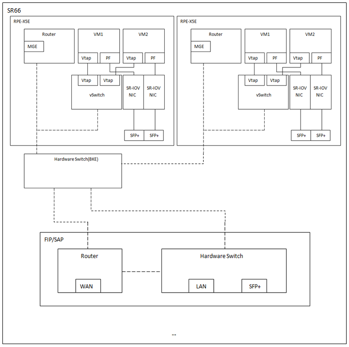
As shown in Figure 1, the router architecture contains the following components:
· VMs—Deployed as needed on the MPU to offer new applications or services. The operating system of a VM is called the guest OS.
· Router—The routing system.
· WAN—WAN ports.
· MGE—Management Ethernet ports.
· SFP+—Physical 10 GigbitEthernet ports offered by single route input/output virtualization (SR-IOV) NICs.
· LAN—LAN ports.
· Hardware switch—Hardware switching module.
· vSwitch—Distributed virtual software switching system, which contains vSwitches deployed on MPUs and connects the VMs to the routing system and hardware switch module.
· SR-IOV NIC—NIC built with SR-IOV technology to support hardware-based virtualization. The VM uses SR-IOV physical functions (PF) to access the I/O modules through physical SR-IOV NICs at high performance as if through physical interfaces.
· vTap NIC—Software-based virtual NIC that connects VMs to the vSwitch. The vTap NIC has lower performance than the PF interface.
The vSwitches and SR-IOV NICs provide both Layer 2 and Layer 3 connectivity for VMs.
Figure 1 SR6600 router architecture with the RPE-X5E MPU
VM link modes
Accessing a VM is the same as accessing a host except that the VM is accessed through virtual links. The VMs on the MPU can use vTap and SR-IOV PF interfaces for network connectivity.
· vTap link mode—The vTap interface connects a VM to a vSwitch for traffic forwarding. The vTap link is slow because vSwitch forwards traffic in software.
· PF link mode—The PF interface connects a VM to an SR-IOV NIC, which allows the VM to have direct access to the I/O module at high performance as if through a physical interface.
|
|
NOTE: To use SR-IOV PFs for VM connectivity, you must install an SR-IOV NIC driver in the guest OS of VMs. If the guest OS is not compatible with the driver, you can only use the vTap NIC for VM connectivity. |
Communication mechanisms
The RPE-X5E MPU provides the same functionality as a traditional router. The following information only describes the communication mechanisms related to VMs.
VM-to-VM traffic forwarding
Figure 2 illustrates the forwarding path for the traffic between the vTap interfaces of two VMs on different MPUs. The vSwitch is used to forward the traffic.
Figure 2 vTap-to-vTap traffic forwarding

Figure 3 illustrates the forwarding path for the traffic from a vTap interface on one VM to a PF interface on another VM.
1. The source SR-IOV NIC forwards the traffic to the vSwitch.
2. The vSwitch forwards the traffic to the hardware switch of a forwarding module through an SPF+ port.
3. The hardware switch forwards the traffic to the destination PF interface through the SPF+ ports of the forwarding module and the destination SR-IOV NIC.
The path of PF-to-vTap traffic forwarding is the reverse of the vTap-to-PF traffic forwarding path.
Figure 3 vTap-to-PF traffic forwarding

Figure 4 illustrates the forwarding path for the traffic between the PF interfaces of two VMs on different MPUs. The SR-IOV NICs forward the traffic through SPF+ ports.
Figure 4 PF-to-PF traffic forwarding

VM-to-WAN traffic forwarding
Figure 5 illustrates the forwarding path for the traffic from a vTap interface on a VM to a WAN port on a forwarding module.
1. The vTap interface forwards the traffic to the vSwitch.
2. The vSwitch forwards the traffic to the hardware switch of the forwarding module.
3. The hardware switch forwards the traffic to the routing system.
4. The routing system forwards the traffic to the WAN port.
Figure 5 vTap-to-WAN traffic forwarding
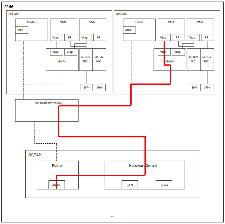
Figure 6 illustrates the forwarding path for the traffic from a PF interface on a VM to a WAN port on the device.
1. The SR-IOV NIC forwards the traffic to the hardware switch of a forwarding module through an SFP+ port.
2. The hardware switch forwards the traffic to the routing system.
3. The routing system forwards the traffic to the WAN port.
Figure 6 PF-to-WAN traffic forwarding

VM-to-LAN traffic forwarding
Figure 7 illustrates the forwarding path for the traffic from a vTap interface on a VM to a LAN port on the device.
1. The vTap interface forwards the traffic to the vSwitch.
2. The vSwitch forwards the traffic to the hardware switch of a forwarding module.
3. The hardware switch forwards the traffic to the LAN port.
Figure 7 vTap-to-LAN traffic forwarding
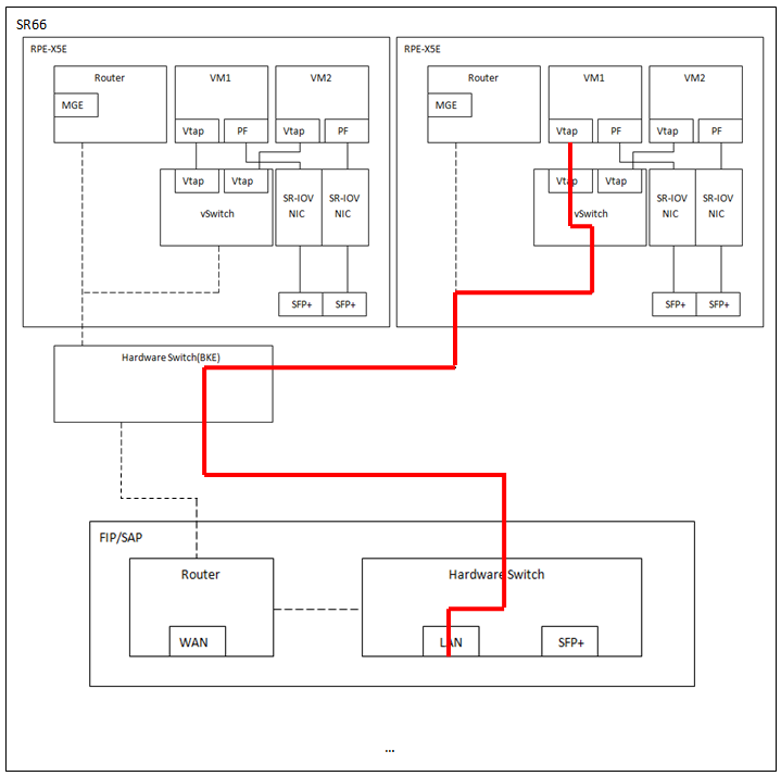
Figure 8 illustrates the forwarding path for the traffic from a PF interface on a VM to a LAN port on the device. The SR-IOV NIC forwards the traffic to the hardware switch of a forwarding module. Then, the hardware switch forwards the traffic to the LAN port.
Figure 8 PF-to-LAN traffic forwarding

Restrictions: Hardware compatibility with VMs
Only the RPE-X5E MPU supports VMs.
VM configuration tasks at a glance
To configure and manage VMs, perform the following tasks:
? Adding an SR-IOV NIC to a VM
? Removing an SR-IOV NIC from a VM
? Specifying a VLAN for a vTap NIC
? Removing a vTap NIC from a VM
? Allocating CPU cores to the VM plane
? Binding vCPUs to physical CPUs
4. Monitoring and maintaining VMs
? Displaying information about VMs
? Monitoring the resource usage of VMs
Creating a VM
About this task
To create a VM, execute the install vm-name command or install a .pkg VM file exported from an existing device. A .pkg file contains all files that make up a VM. You can use the export vm command to export the .pkg file for a VM to the specified path.
Restrictions and guidelines
If you are using the VM to provide H3C vFW services, use the following guidelines when you specifying memory for the VM:
· If the vFW requires only one CPU core, allocate 2 GB of memory to the VM.
· If the vFW requires two CPU cores, allocate 4 GB of memory to the VM.
· If the vFW requires four CPU cores, allocate 8 GB of memory to the VM.
Prerequisites
If you are creating a VM by manually specifying its parameters:
· Use the create-disk command to create a disk for the VM as described in "Adding a disk to a VM."
· (Optional.) Prepare the VM guest OS file. When you install the VM, specify this file as the CD-ROM file.
If you are using a .pkg file to create a VM, export an existing .pkg file as described in "Exporting a VM."
Procedure
1. Enter system view.
system-view
2. Enter VMM view.
vmm
3. Install a VM. Choose one of the following methods:
? Install a VM based on the specified parameters.
In standalone mode:
install slot slot-number vm-name vm-name vcpu vcpu-count memory size vncport vncport disk disk-file format { raw | qcow2 } [ cdrom cdrom-file ] [ vnic { vtap [ mac mac-address ] [ vlan vlan-id ] | sriov pf pfid } ]
In IRF mode:
install chassis chassis-number slot slot-number vm-name vm-name vcpu vcpu-count memory size vncport vncport disk disk-file format { raw | qcow2 } [ cdrom cdrom-file ] [ vnic { vtap [ mac mac-address ] [ vlan vlan-id ] | sriov pf pfid } ]
? Install a VM by using a .pkg file.
In standalone mode:
install slot slot-number vm-pkg pkg-path
In IRF mode:
install chassis chassis-number slot slot-number vm-pkg pkg-path
Starting a VM
About this task
For a VM can start successfully, you must make sure the system has sufficient memory. In addition to the memory for VMs, you must also make sure sufficient memory is available for the VM plane to run.
If system memory becomes insufficient while it is running, the system automatically stops the VM that uses the most memory.
Prerequisites
Make sure the VM you want to start has been created on the device and the system has sufficient memory to start the VM.
Procedure
1. Enter system view.
system-view
2. Enter VMM view.
vmm
3. Start a VM.
In standalone mode:
start vm slot slot-number vm-name
In IRF mode:
start vm chassis chassis-number slot slot-number vm-name
Resizing a VM
After you create a VM, you can resize the VM as needed by adding or removing its resources such as disks and memory.
Adding a disk to a VM
About this task
Disks for VMs are in the form of disk files. You add a disk to a VM by associating the disk file with the VM.
A VM supports one IDE controller, to which you can attach a maximum of four disks, which are named hda, hdb, hdc, and hdd in the XML configuration file. The hdc disk is reserved for CD-ROM.
Restrictions and guidelines
To have the add operation to take effect, you must reboot the VM.
After you add a disk to a VM, you must partition, format, and mount that disk on the VM before you can use it.
You can mount only one disk to a vFW VM.
You cannot add a disk to multiple VMs.
Procedure
1. Enter system view.
system-view
2. Enter VMM view.
vmm
3. Create a VM disk.
create-disk disk-file size size format { raw | qcow2 }
4. Add the disk to a VM.
In standalone mode:
add disk vm slot slot-number vm-name format { raw | qcow2 } disk-file path-file
In IRF mode:
add disk vm chassis chassis-number slot slot-number vm-name format { raw | qcow2 } disk-file path-file
Removing a disk from a VM
Restrictions and guidelines
For the deletion to take effect, you must reboot the VM.
Procedure
1. Enter system view.
system-view
2. Enter VMM view.
vmm
3. Remove a disk from a VM.
In standalone mode:
delete disk vm slot slot-number vm-name target target
delete disk vm chassis chassis-number slot slot-number vm-name target target
Configuring the CD-ROM
About this task
After the VM is installed, you can specify any image file as a CD-ROM file to copy that file to the VM.
Procedure
1. Enter system view.
system-view
2. Enter VMM view.
vmm
3. Configure the CD-ROM.
In standalone mode:
set cdrom vm slot slot-number vm-name cdrom-file cdrom-file
In IRF mode:
set cdrom vm chassis chassis-number slot slot-number vm-name cdrom-file cdrom-file
Adding an SR-IOV NIC to a VM
About this task
Each RPE-X5E MPU provides two SR-IOV NICs for VMs. A VM can use the PF interface of a NIC exclusively for communication.
Perform this task to allocate an SR-IOV NIC to a VM by specifying the MAC address of a PF.
Restrictions and guidelines
For an SR-IOV NIC to operate on a VM, you must install an SR-IOV NIC driver on the VM.
Procedure
1. Enter system view.
system-view
2. Enter VMM view.
vmm
3. Add an SR-IOV NIC to a VM.
In standalone mode:
add sriov vm slot slot-number vm-name pf pfid
In IRF mode:
add sriov vm chassis chassis-number slot slot-number vm-name pf pfid
Removing an SR-IOV NIC from a VM
About this task
Remove a PF from a VM to remove the SR-IOV NIC from that VM.
Restrictions and guidelines
For the remove operation to take effect, you must reboot the VM.
Procedure
1. Enter system view.
system-view
2. Enter VMM view.
vmm
3. Remove an SR-IOV NIC from a VM.
In standalone mode:
delete sriov vm slot slot-number vm-name pf pfid
In IRF mode:
delete sriov vm chassis chassis-number slot slot-number vm-name pf pfid
Adding a vTap NIC to a VM
About this task
The Comware system has reserved MAC addresses for vTap NICs. When you add a vTap NIC to a VM, select a MAC address to uniquely identify it.
Restrictions and guidelines
When you add vTap NICs to a VM or multiple VMs, you must make sure their MAC addresses are unique.
Procedure
1. Enter system view.
system-view
2. Enter VMM view.
vmm
3. Add a vTap NIC to a VM.
In standalone mode:
add vtap vm slot slot-number vm-name mac mac-address [ vlan vlan-id ]
In IRF mode:
add vtap vm chassis chassis-number slot slot-number vm-name mac mac-address [ vlan vlan-id ]
Specifying a VLAN for a vTap NIC
About this task
Procedure
1. Enter system view.
system-view
2. Enter VMM view.
vmm
3. Specify a VLAN for the vTap NIC of a VM.
In standalone mode:
set vtap vm slot slot-number vm-name mac mac-address vlan vlan-id
In IRF mode:
set vtap vm chassis chassis-number slot slot-number vm-name mac mac-address vlan vlan-id
Removing a vTap NIC from a VM
Restrictions and guidelines
For the remove operation to take effect, you must reboot the VM.
Procedure
1. Enter system view.
system-view
2. Enter VMM view.
vmm
3. Remove a vTap NIC from a VM.
In standalone mode:
delete vtap vm slot slot-number vm-name mac mac-address
In IRF mode:
delete vtap vm chassis chassis-number slot slot-number vm-name mac mac-address
Allocating CPU cores to the VM plane
About this task
Functionalities of the system are categorized into the control, data, and VM planes. The virtualization functions run on the VM plane.
By default, the control plane is allocated one physical CPU core, the data plane is allocated one physical CPU core, and the VM plane is allocated the remaining physical CPU cores.
To change the number of physical CPU cores assigned to the VM plane, perform this task. Then, the system automatically allocates one CPU core to the control plane, and allocates the remaining CPU cores to the data plane.
Restrictions and guidelines
For the configuration in this task to take effect, you must reboot the MPU that hosts the VMs.
After you modify the number of CPU cores allocated to the VM plane, you must reallocate vCPUs to VMs. For the reallocation to take effect on a VM, you must reboot the VM.
Procedure
1. Enter system view.
system-view
2. Allocate physical CPU cores to the VM plane.
In standalone mode:
set vcpu-pool slot slot-number vcpu-number
In IRF mode:
set vcpu-pool chassis chassis-number slot slot-number vcpu-number
Allocating vCPUs to a VM
1. Enter system view.
system-view
2. Enter VMM view.
vmm
3. Allocate vCPUs to a VM.
In standalone mode:
set vcpu vm slot slot-number vm-name vcpu-count vcpu-count
In IRF mode:
set vcpu vm chassis chassis-number slot slot-number vm-name vcpu-count vcpu-count
Binding vCPUs to physical CPUs
1. Enter system view.
system-view
2. Enter VMM view.
vmm
3. Bind a vCPU on a VM to a physical CPU.
In standalone mode:
set vcpupin vm slot slot-number vmname vcpuindex vcpuindex cpuindex cpuindex
In IRF mode:
set vcpupin vm chassis chassis-number slot slot-number vmname vcpuindex vcpuindex cpuindex cpuindex
Allocating memory to a VM
About this task
Typically, the Comware system requires 2 GB of memory to run. You can allocate the remaining memory to VMs.
To ensure that a VM can operate, make sure the VM is allocated a minimum of 512 MB of memory. If the device has more than 16 GB of memory, you can allocate a maximum of 15 GB of memory to VMs.
Procedure
1. Enter system view.
system-view
2. Enter VMM view.
vmm
3. Allocate memory to a VM.
In standalone mode:
set memory vm slot slot-number vm-name size size
In IRF mode:
set memory vm chassis chassis-number slot slot-number vm-name size size
Configuring VNC for a VM
About this task
To remotely access the VM desktop from a VNC viewer (or client), perform this task.
Procedure
1. Enter system view.
system-view
2. Enter VMM view.
vmm
3. Set the VNC port number of the VM.
In standalone mode:
set vnc vm slot slot-number vm-name vncport vncport
In IRF mode:
set vnc vm chassis chassis-number slot slot-number vm-name vncport vncport
4. Set the VNC login password of the VM.
In standalone mode:
set vnc vm slot slot-number vm-name setpasswd password
In IRF mode:
set vnc vm chassis chassis-number slot slot-number vm-name setpasswd password
5. Set the IP address for accessing the VM.
In standalone mode:
set vnc vm slot slot-number vm-name listen ip-address
In IRF mode:
set vnc vm chassis chassis-number slot slot-number vm-name listen ip-address
6. (Optional.) Delete the VNC login password on the VM.
In standalone mode:
set vnc vm slot slot-number vm-name delpasswd
In IRF mode:
set vnc vm chassis chassis-number slot slot-number vm-name delpasswd
Enabling VM auto-start
About VM auto-start
Perform this task to enable a VM to start up automatically when the MPU starts.
Procedure
1. Enter system view.
system-view
2. Enter VMM view.
vmm
3. Enable VM auto-start.
In standalone mode:
autostart vm slot slot-number vm-name
In IRF mode:
autostart vm chassis chassis-number slot slot-number vm-name
By default, VM auto-start is disabled.
Monitoring and maintaining VMs
Displaying information about VMs
Perform all display tasks in any view.
· Display the VM list.
display vmlist
· Display the virtual disk list.
display vmdisklist
· Display detailed information about a VM.
display vm
· Display network interface information about a VM.
display vminterface
· Display the VNC port number of a VM.
display vncport
· Display the bindings between vCPUs and physical CPUs for a VM.
display vmcpupin
· Display passthrough NIC information.
display passthrough
Monitoring the resource usage of VMs
Perform all display tasks in any view.
· Display the number of CPUs allocated to VMs.
display vcpu-pool
· Display the CPU usage of a VM.
display vmcpu-usage
· Display the memory usage of a VM.
display vmmem-usage
· Display disk usage information about a VM.
display vmdisk-usage
Suspending a VM
About this task
Perform this task to suspend a VM. The VM will then be placed in Paused state.
Procedure
1. Enter system view.
system-view
2. Enter VMM view.
vmm
3. Suspend a VM.
In standalone mode:
suspend vm slot slot-number vm-name
In IRF mode:
suspend vm chassis chassis-number slot slot-number vm-name
Resuming a suspended VM
1. Enter system view.
system-view
2. Enter VMM view.
vmm
3. Resume a suspended VM.
In standalone mode:
resume vm slot slot-number vm-name
In IRF mode:
resume vm chassis chassis-number slot slot-number vm-name
Stopping a VM
About this task
When the MPU reboots, the system automatically attempts to stop all VMs on the MPU securely within 5 minutes. If VMs are operating incorrectly, it will take 6 minutes to stop each VM. If the system fails to stop a VM within 6 minutes, it will force that VM down.
Perform this task to manually stop a VM.
Restrictions and guidelines
|
|
CAUTION: A force stop might cause data loss. Do not force a VM down unless necessary. |
If a VM fails to stop because of an abnormal process, access the VM, manually close the process, and retry the stop operation.
If the VM does not have an operating system, you must specify the force keyword to force it down.
Procedure
1. Enter system view.
system-view
2. Enter VMM view.
vmm
3. Stop a VM.
In standalone mode:
stop vm slot slot-number vm-name [ force ]
In IRF mode:
stop vm chassis chassis-number slot slot-number vm-name [ force ]
Backing up a VM
About this task
Perform this task to back up a VM to a .vmb file.
Make sure the file path is correct and the target storage medium has sufficient storage space.
Procedure
1. Enter system view.
system-view
2. Enter VMM view.
vmm
3. Back up a VM.
In standalone mode:
backup vm slot slot-number vm-name backup-path
In IRF mode:
backup vm chassis chassis-number slot slot-number vm-name backup-path
Restoring a VM
About this task
Perform this task to restore a VM by using a .vmb backup file. After the restoration, the VM image is automatically saved in the path before the restoration.
Make sure the system has sufficient storage space to restore the VM.
Procedure
1. Enter system view.
system-view
2. Enter VMM view.
vmm
3. Restore a VM by using a .vmb backup file.
In standalone mode:
restore slot slot-number pakagepath backup-image-path
In IRF mode:
restore chassis chassis-number slot slot-number pakagepath backup-image-path
Exporting a VM
About this task
Perform this task to export a VM to a .pkg file.
Make sure you have access permissions to the target path and the target path has sufficient storage space.
Procedure
1. Enter system view.
system-view
2. Enter VMM view.
vmm
3. Export a VM.
In standalone mode:
export vm slot slot-number vm-name pkg-path
In IRF mode:
export vm chassis chassis-number slot slot-number vm-name pkg-path
Uninstalling a VM
Prerequisites
You must stop a VM before you can uninstall it.
Procedure
1. Enter system view.
system-view
2. Enter VMM view.
vmm
3. Uninstall a VM.
In standalone mode:
uninstall vm slot slot-number vm-name
In IRF mode:
uninstall vm chassis chassis-number slot slot-number vm-name
