- Table of Contents
- Related Documents
-
| Title | Size | Download |
|---|---|---|
| 01-Text | 2.92 MB |
Contents
Creating a deployment task from the QoS policy
Deploying interface QoS configurations
Configuring a CAR list, PQ list, or CQ list for a device
Creating a deployment task for interface QoS configurations
QoSM navigation menu and common operations
Managing the QoS capability set
Viewing the QoS capability set of a device
Viewing the QoS capability set of an interface
Reloading the QoS capability set for a device
Accessing the QoS Configuration Info page
Exporting/Importing a classifier
Exporting and Importing a behavior
Exporting and Importing a QoS policy
Viewing the details of a service
Accessing the deployment task list page
Viewing the details of a deployment task
Adding a non-MQC deployment task
Deleting a single deployment task
Deleting deployment tasks in batches
Executing a deployment task immediately
Resuming a suspended deployment task
Access control and bandwidth control configuration examples
Network requirements and analysis
QoSM overview
Developed based on the IMC Platform, the QoS Manager (QoSM) is a component that manages QoS configurations of devices. QoS configurations mitigate bandwidth, delay, jitter, and packet loss issues in the network.
QoSM provides differentiated treatment for traffic by classifying the traffic and taking actions on different classes of traffic.
QoSM enables you to use network resources more effectively and provides guaranteed services for network traffic.
Features and benefits
QoSM has the following features and benefits:
· Configuration detection and audit—QoSM can detect QoS capability sets that are supported by devices. This can prevent administrators from deploying QoS configurations beyond devices' QoS capabilities. If the administrator deploys QoS configurations beyond devices' QoS capabilities, QoSM filters unsupported QoS configurations. QoSM can also obtain the QoS configurations on devices and detect QoS configuration changes by comparing them with the set baseline QoS configurations.
· Quick deployment—QoSM quickly deploys common services and self-defined services to device interfaces or VLANs. Common services include voice, video, SOM, and network protocol services.
· Simplified configuration—Deploys QoS configurations by performing Select Device Interface/VLAN > Select Policy > Generate Task operations on a graphical interface.
· Configuration reuse—Any traffic classes can be associated with any traffic behaviors to form policies, independently of devices. A policy can be applied to different devices.
Functions
QoSM provides the following functions:
· Quick Start—Provides information about basic concepts and functions in QoSM.
· QoS Device—Provides the following functions, which enable you to:
¡ View the QoS features supported by devices.
¡ View the QoS features that are already configured on devices.
¡ Set the baseline to monitor QoS configuration changes.
· QoS Resource—QoS resources include traffic classes, traffic behaviors, and flow policies:
¡ Classifier—Classifies packets based on the packet characteristics, such as IP addresses, MAC addresses, and port numbers. Traffic classes provide the basis for differentiated treatment of traffic.
¡ Behavior—Defines actions to take on classified traffic, such as traffic policing, traffic shaping, rate limiting, and congestion management.
¡ QoS Policy—Defines flow polices by associating classes with behaviors. Flow polices can be deployed to interfaces or VLANs.
· Deployment management—Includes Service Deployment and Deployment Task:
¡ Business Deploy—Predefines traffic classes and behaviors for common services, such as voice and video. Administrators need to manually configure some parameters in behaviors. To deploy the policies for common services, administrators only need to select interfaces or VLANs. Administrators can also define common services.
¡ Deployment Task—Generates deployment tasks by selecting interfaces or VLANs for preconfigured flow polices. QoSM deploys flow policies to the interfaces or VLANs at the specified time.
Configuration procedures
QoSM enables you to deploy QoS policies and interface QoS configurations to QoS-capable devices.
Configuration prerequisites
To deploy QoS policies and interface QoS configurations to a device, the following conditions must be met:
· The device is QoS capable.
· The device has been added to IMC and configured with correct SNMP and Telnet settings.
· The device has been synchronized in IMC.
Deploying a QoS policy
You can deploy a QoS policy to multiple interfaces on multiple devices. The recommended configuration procedure is as follows:
1. Create a classifier.
2. Create a behavior.
3. Create a QoS policy.
4. Create a deployment task from the QoS policy.
Creating a classifier
A classifier classifies packets by using one or more match criteria and specifies the match policy (match any or all of the match criteria) through the logical relationship among the match criteria.
To create a classifier:
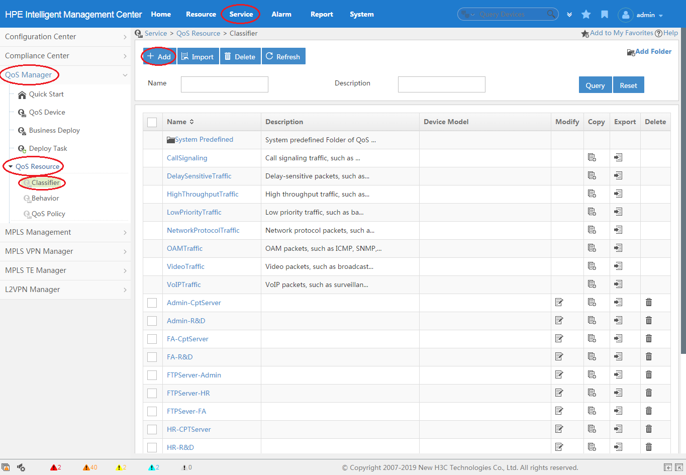
1. Click the Service tab, as shown in Figure 1.
2. From the navigation tree, select QoS Manager > QoS Resource > Classifier.
3. Click Add.
For more information about creating a classifier, see "Adding a classifier."
Figure 1 Creating a classifier
Creating a behavior
A behavior specifies actions to take on matching packets.
To create a behavior:
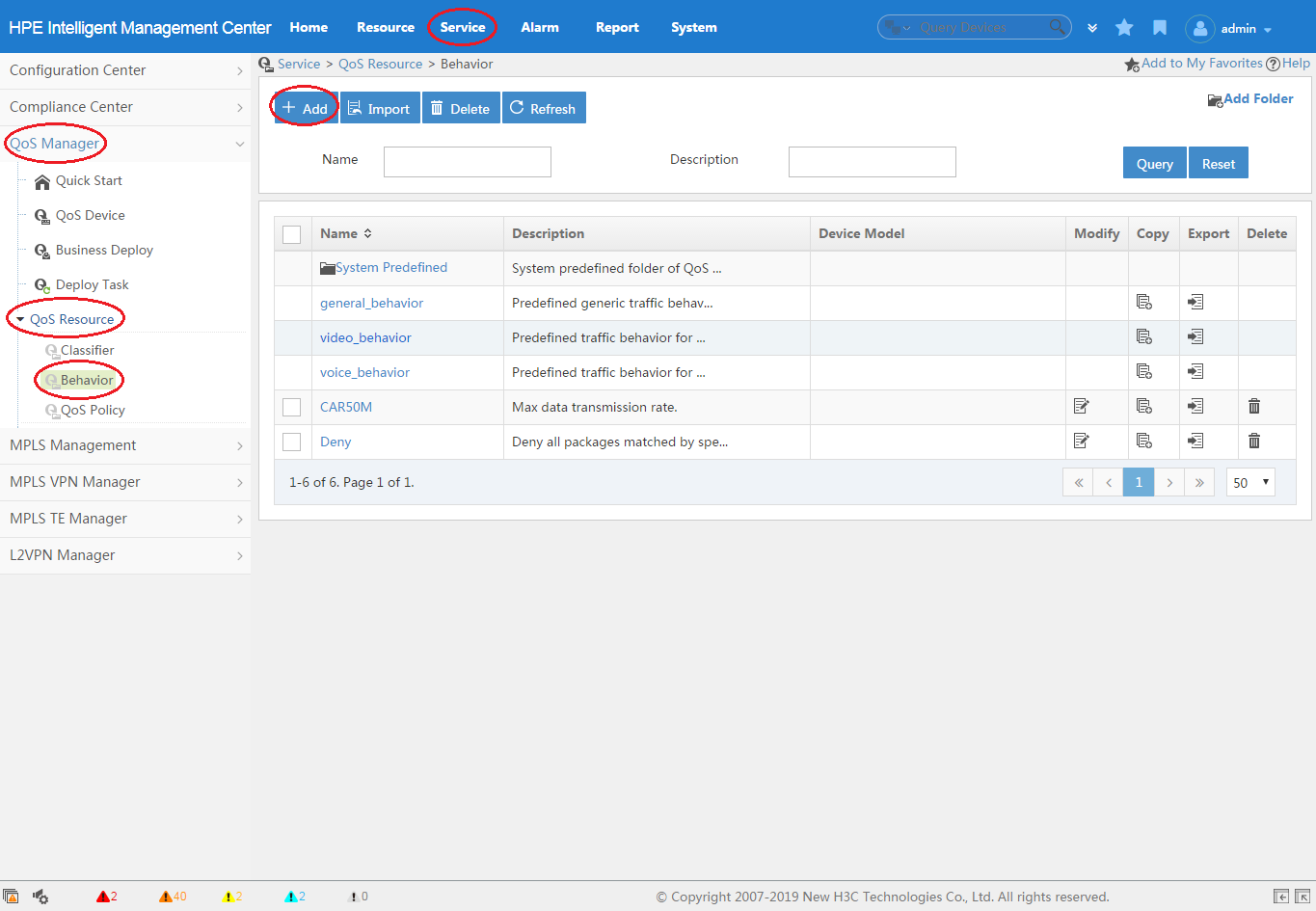
1. Click the Service tab, as shown in Figure 2.
2. From the navigation tree, select QoS Manager > QoS Resource > Behavior.
3. Click Add.
For more information about creating a behavior, see "Adding a behavior."
Creating a QoS policy
A QoS policy associates classifiers with behaviors; it can contain multiple classifier-behavior associations.
To create a QoS policy:
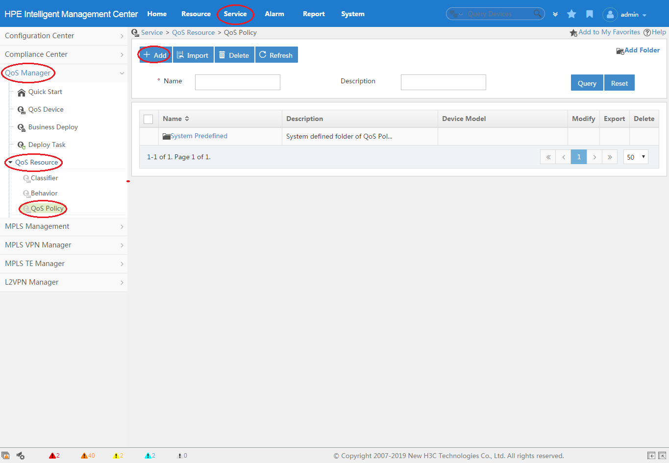
1. Click the Service tab, as shown in Figure 3.
2. From the navigation tree, select QoS Manager > QoS Resource > QoS Policy.
3. Click Add.
For more information about creating a QoS policy, see "Adding a QoS policy."
Figure 3 Creating a QoS policy
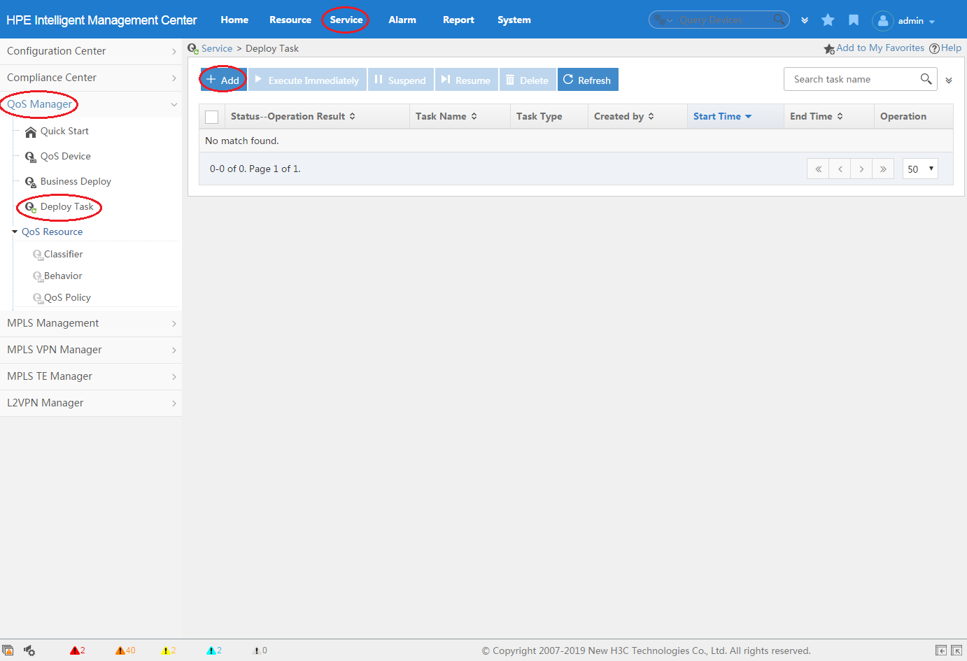
Creating a deployment task from the QoS policy
You can use a deployment task for a QoS policy to deploy the QoS policy to device interfaces or VLANs and to monitor the deployment process.
To create a deployment task from the QoS policy:
1. Click the Service tab, as shown in Figure 4.
2. From the navigation tree, select QoS Manager > Deploy Task.
3. Click Add.
QoSM provides multiple entries for creating a deployment task for a QoS policy. For more information, see "Adding an MQC deployment task."
Figure 4 Creating a deployment task from the QoS policy
Deploying interface QoS configurations
Interface QoS configurations can be deployed only to physical interfaces on devices. The recommended configuration procedure is as follows:
1. Configure a CAR list, PQ list, or CQ list.
2. Create a deployment task from interface QoS configurations.
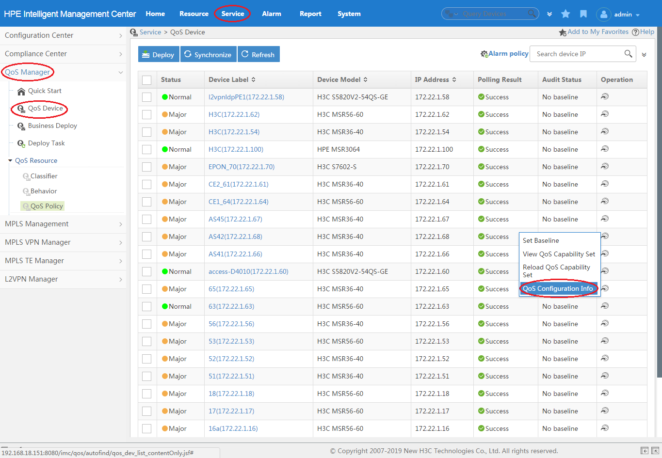
Configuring a CAR list, PQ list, or CQ list for a device
Before configuring traffic policing for an interface, configure a CAR list for its device. Before configuring PQ or CQ for an interface, configure a PQ or CQ list for its device. This task is not needed for configuring other QoS features on an interface. Only routers support configuring CAR lists, PQ lists, and CQ lists.
To create a CAR list, PQ list, or CQ list for a device:
1. Click the Service tab, as shown in Figure 5.
2. From the navigation tree, select QoS Manager > QoS Device.
The QoS Device page appears.
3. Click the Operation
icon ![]() for the
device, and then select QoS Configuration Info from
the menu.
for the
device, and then select QoS Configuration Info from
the menu.
Figure 5 Accessing the QoS Configuration Info page
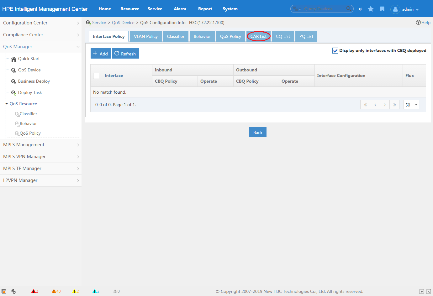
4. Click the CAR List, PQ List, or CQ List tab, as shown in Figure 6.
For information about configuring a CAR list, PQ list, or CQ list, see "CAR List", "CQ List", and "PQ List."
Figure 6 Configuring a CAR list, PQ list, or CQ list
Creating a deployment task for interface QoS configurations
You can use a deployment task for interface QoS configurations to deploy QoS configurations (not in the form of QoS policies) to device interfaces and to monitor the deployment process.
To create a deployment task for interface QoS configurations:
1. Click the Service tab.
2. From the navigation tree, select QoS Manager > Deploy Device.
The QoS Device page appears.
3. Click the Operation
icon ![]() for the
device, and then select QoS Configuration Info from
the menu.
for the
device, and then select QoS Configuration Info from
the menu.
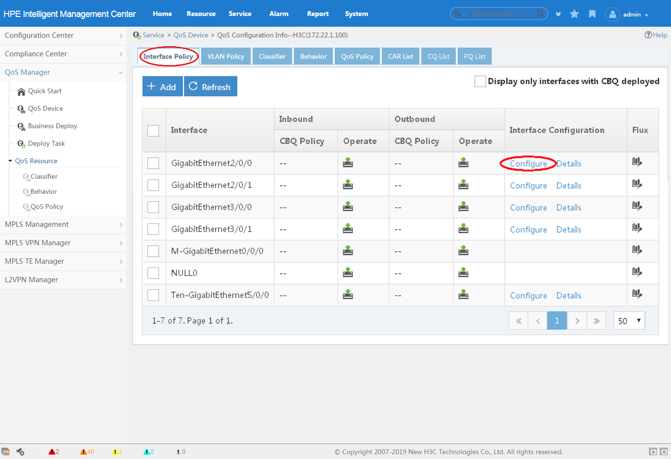
The QoS Configuration Info page appears and displays the Interface Policy Application tab.
4. Click Configure in the Interface Configuration column for the interface that you want to configure, as shown in Figure 7.
For more information about creating a deployment task for interface QoS configurations, see "Adding a non-MQC deployment task."
Figure 7 Creating a deployment task for interface QoS configurations
QoSM navigation menu and common operations
The following information guides you quickly through the main functions of the QoSM component.
Navigation menus
1. Click the Service tab on the top navigation bar.
2. From the left navigation tree, click QoS Manager to expand the QoSM navigation menus. Table 1 explains the navigation menu options.
Table 1 QoSM navigation menu options
|
Navigation menu option |
Task |
|
Quick Start |
View the workflow for the use of QoSM service modules and access the modules. |
|
QoS Device |
Manage QoS-capable devices, view QoS capability sets and QoS configurations of devices, and set the baseline QoS configurations. |
|
Business Deploy |
Associate traffic classes with traffic behaviors for common services and quickly deploy QoS configurations to the common services. |
|
Deploy Task |
Add, modify, or delete tasks; deploy or undeploy tasks. |
|
QoS Resource |
Add, modify, or delete traffic classes, traffic behaviors, or policies. |
Common operations
Sorting a list
You can sort a list by every field that
contains a Sort icon ![]() in the column
label:
in the column
label:
· When the list is sorted by a field in ascending
order, the column label of the selected field is blue and contains an Ascending icon ![]() .
.
· When the list is sorted by a field in descending
order, the column label of the selected field is blue and contains a Descending icon ![]() .
.
Navigating a list
If a list contains enough entries, use the following aids to navigate the list:
· Click the Next Page
icon ![]() to page
forward in the list.
to page
forward in the list.
· Click the Last Page
icon ![]() to page
forward to the end of the list.
to page
forward to the end of the list.
· Click the Previous Page
icon ![]() to page
backward in the list.
to page
backward in the list.
· Click the First Page
icon ![]() to page
backward to the front of the list.
to page
backward to the front of the list.
· Click a page number to display the page in the list.
· Select 8, 15, 50, 100, or 200 at the bottom of the list to specify how many items per page you want to display.
Adding devices
You can add devices from the IMC Platform to QoSM.
Accessing the window for selecting devices
In the Apply Policy to Interface or Apply Policy to VLAN area, click Select Device. The window for selecting devices appears, from which you can filter devices by view or advanced query.
Filtering devices by view
1. In the Query Conditions area, click the By View tab.
2. Click the Expand icon ![]() to the left of
the IP View, Device View, or Custom View field, and then select a subview.
to the left of
the IP View, Device View, or Custom View field, and then select a subview.
The views are:
¡ IP View—Displays devices by network segment.
¡ Device View—Displays devices by device category.
¡ Custom View—Displays devices by custom view. This view has a subview named Devices Not In Views to display devices that do not belong to any custom view.
All devices in the subview are displayed in the Devices Found area.
Filtering devices by advanced query
1. In the Query Conditions area, click the Advanced tab.
2. Specify one or more of the following query criteria:
¡ Device IP—Enter an IP address for devices.
If Exact Query is selected, enter a complete IPv4 address. If Exact Query is not selected, enter a partial or complete IPv4 address.
¡ Device IP List—Click the Configuration icon ![]() next to the Device IP List field to
perform an exact query for multiple devices.
next to the Device IP List field to
perform an exact query for multiple devices.
In the Device IP List Configuration window, enter multiple IP addresses separated by commas, semicolons, or carriage returns, click Add, and then click OK.
¡ Device Label—Enter a partial or complete device label.
¡ Device Status—Select a device state from the list: Unmanaged, Unknown, Normal, Warning, Minor, Major, or Critical.
¡ Device Category—Select a device type from the list: Routers, Switches, Servers, Security, Storage, Wireless, Voice, Surveillance, Video, Virtual Devices, Module, Application Controller, SAN Controller, Printers, UPS, Desktops, or Others.
¡ Device Series—Select device series from the list. Options include all device series that are added to the IMC Platform. You can select one or all device series of a vendor.
¡ Contact—Enter partial or complete contact information for devices. This criterion is case insensitive.
¡ Location—Enter partial or complete location information for devices. This criterion is case insensitive.
¡ Device Reachability—Select a reachability state from the list: Reachable or Unreachable.
Empty fields are ignored.
3. Click Query.
All matching devices are displayed in the Devices Found area.
Selecting devices
1. Add devices to the Selected Devices area:
¡ To
add one or more devices, select the devices in the Devices
Found area, and then click the Add icon ![]() .
.
¡ To
add all devices, click the Add All icon ![]() .
.
2. Remove undesired devices from the Selected Devices area:
¡ To
remove one or more devices, select the devices in the Selected
Devices area, and then click the Remove icon
![]() .
.
¡ To
remove all devices, click the Remove All icon ![]() .
.
3. Click OK.
|
|
NOTE: · If less than two devices are found, the window does not include
the Add All icon · To select multiple devices, press Ctrl when you select the devices. |
Adding interfaces
1. In the Apply Policy to
Interface area, click the Select Device Interface icon ![]() in the Number of
Interfaces (Inbound Direction) or Number of Interfaces (Outbound Direction) column.
in the Number of
Interfaces (Inbound Direction) or Number of Interfaces (Outbound Direction) column.
The window for selecting interfaces appears.
2. Add interfaces to the Selected Interface area:
¡ To
add one or more interfaces, select the interfaces in the Device
Interface area, and then click the Add icon ![]() .
.
¡ To
add all interfaces, click the Add All icon ![]() .
.
3. Remove undesired interfaces from the Selected Interface area:
¡ To
remove one or more interfaces, select the interfaces in the Selected Interface area, and then click the Remove icon ![]() .
.
¡ To
remove all interfaces, click the Remove All icon ![]() .
.
4. Click OK.
|
|
NOTE: · To select multiple interfaces, press Ctrl when you select the interfaces. |
Adding VLANs
1. In the Apply Policy to VLAN area, click the Select VLAN icon ![]() in the VLAN (Inbound) or VLAN (Outbound) Column.
in the VLAN (Inbound) or VLAN (Outbound) Column.
The window for selecting VLANs appears.
2. Add VLANs to the Selected VLAN area:
¡ To
add one or more VLANs, select the VLANs in the Device VLAN area, and then
click the Add icon ![]() .
.
¡ To
add all VLANs, click the Add All icon ![]() .
.
3. Remove undesired VLANs from the Selected VLAN area:
¡ To
remove one or more VLANs, select the VLANs in the Selected
VLAN area, and then click the Remove icon ![]() .
.
¡ To
remove all VLANs, click the Remove All icon ![]() .
.
4. Click OK.
|
|
NOTE: · To select multiple VLANs, press Ctrl when you select the VLANs. |
Quick Start
The Quick Start page provides an overview of functional modules in QoSM and the entry for each functional module.
To access the Quick Start page:
1. Click the Service tab, as shown in Figure 8.
2. From the navigation tree, select QoS Manager > Quick Start.
The Quick Start page appears. Click the name of a functional module to enter the page for the functional module.
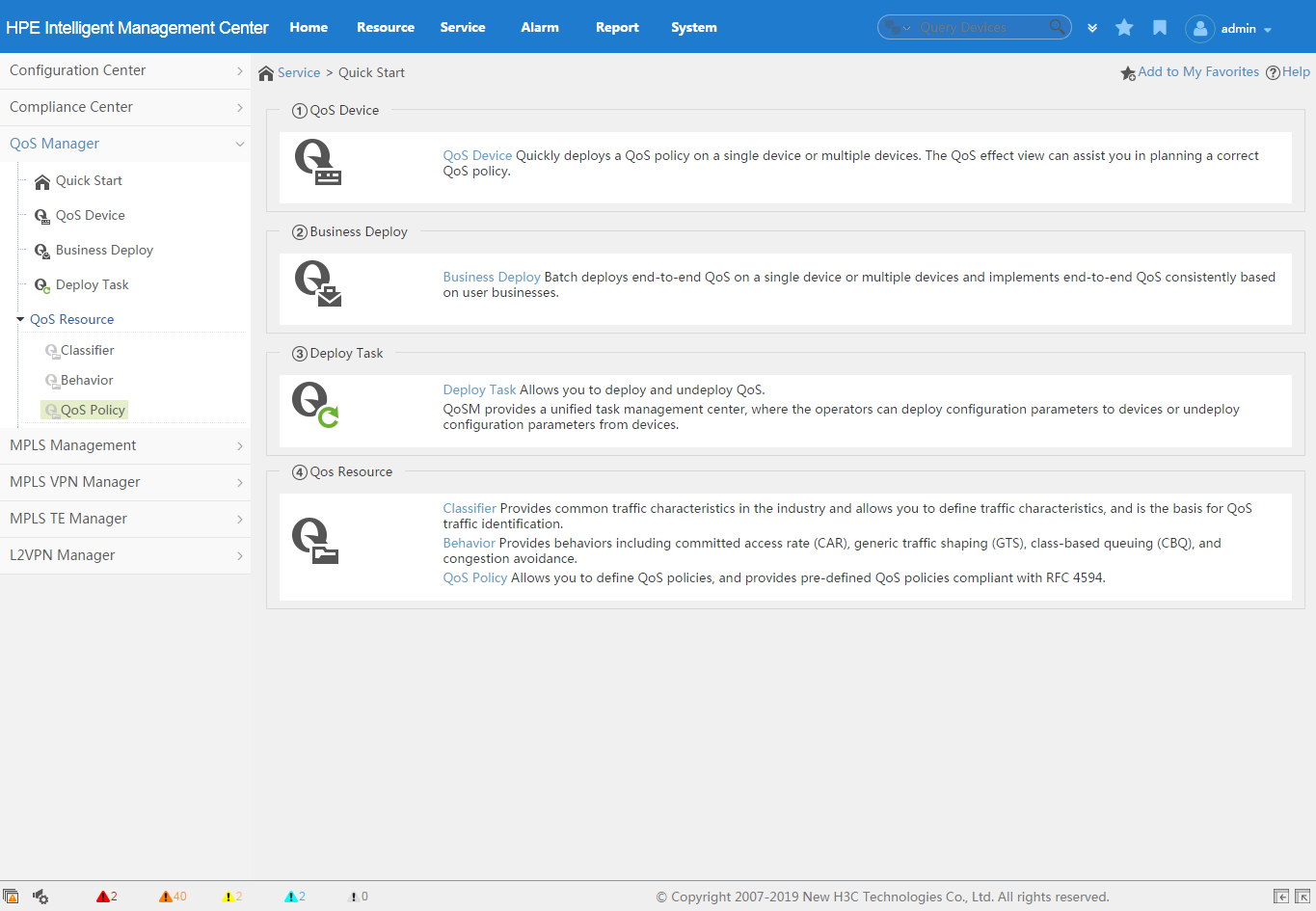
The following describes each functional module:
· QoS Device—Manages QoS-capable network devices and provides an entry for creating deployment tasks.
· Business Deploy—Manages common services and provides an entry for creating deployment tasks. Common services include voice, video, SOM, and network protocol services. Common services can be generated by associating classifiers with behaviors or importing flow policies in the QoS Resource module.
· Deploy Task—Manages all deployment tasks and provides an entry for creating deployment tasks. All user-created deployment tasks are placed in the Deploy Task page.
· QoS Resource—Manages QoS resources, including classifiers, behaviors, and flow policies. Classifier-behavior associations form flow policies.
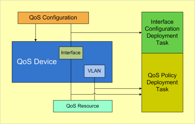
Figure 9 shows the relationship among functional modules in QoSM.
Figure 9 Relationship among functional modules
Managing QoS devices
QoSM enables you to manage QoS-capable devices and provides the following management functions:
· Device/interface QoS capability set—Enables you to view device or interface support for QoS features before deploying QoS configurations.
· QoS configuration information—Enables you to view existing QoS configurations on a device and its interfaces and to deploy or quickly undeploy QoS configurations.
· Baseline and auditing—Informs you of QoS configuration changes on a device or interface.
Through the preceding management functions, you can perform the following tasks in different phases of QoS configuration deployment:
· Learn about a device's support for QoS features and existing QoS configurations on the device before deploying QoS configurations.
· Deploy QoS configurations directly or by using deployment tasks.
· Check whether QoS configurations are successfully deployed and monitor QoS configuration changes on the device.
Accessing the QoS Device page
The QoS Device page displays all QoS-capable devices managed by IMC in a list and is the entrance for some QoS management functions.
To add a device to the device list:
1. Add the device to IMC.
2. Configure correct SNMP settings for the device.
3. Synchronize the device.
To access the QoS Device page:
1. Click the Service tab.
2. From the navigation tree, select QoS Manager > QoS Device.
The QoS Device page appears.
QoS Device list contents
¡ Status—Current status of the device.
¡ Device Label—Label of the device.
¡ Device Model—Model of the device.
¡ IP Address—IP address of the device. If the device has multiple IP addresses, this field displays the IP address entered when the device was added to IMC.
¡ Polling Result—Synchronization result of device configuration information. The failure cause is indicated if the result is failure.
¡ Audit Status—Audit status for the device. QoSM audits each device by comparing the current QoS configurations on the device with the baseline set for the device. If no baseline is set for the device, No baseline is displayed. If a baseline is set for the device, Not audited, Consistent, or Inconsistent is displayed.
¡ Operation—Provides the following options:
- Set Baseline—Set the current QoS configurations on the device as the baseline.
- Cancel Baseline—Cancel the baseline of the device. This option appears only for devices that have been configured with a baseline.
- View QoS Capability Set—View support of the device for QoS features.
- Reload QoS Capability Set—Reload support of the device for QoS features.
- QoS Configuration Info—View QoS configurations on the device and configure QoS features for the device.
- View Baseline—View the baseline of the device.
QoS Device list buttons
¡ Deploy—Deploy a QoS policy to selected devices.
¡ Synchronize—Synchronize configuration information from selected devices.
¡ Refresh—Refresh the QoS device list.
The QoS Device page also provides the following functions in its upper right corner:
¡ Alarm policy—Configure an alarm policy, so an alarm is sent when the audit result is inconsistent.
¡ Search box—Query
devices by IP address. Fuzzy
matching is supported. Click the Advanced icon ![]() to perform advanced query by device label
and IP address.
to perform advanced query by device label
and IP address.
Managing the QoS capability set
Before configuring QoS on a device, QoSM enables you to learn about the device's QoS capability set. QoSM can automatically obtain the QoS capability set of devices.
Viewing the QoS capability set of a device
1. Access the QoS Device page.
2. Click the Operation
icon ![]() for the device, and select View QoS Capability Set from the
menu.
for the device, and select View QoS Capability Set from the
menu.
The QoS Capacity Information window
appears and presents support details for each QoS function. The ![]() icon next to a
function or parameter indicates that the device supports that function or
parameter. The
icon next to a
function or parameter indicates that the device supports that function or
parameter. The ![]() icon next to a function or parameter indicates that the device does
not support that function or parameter. Table 2
describes the functions and parameters.
icon next to a function or parameter indicates that the device does
not support that function or parameter. Table 2
describes the functions and parameters.
Table 2 Functions and parameters
|
QoS function |
Subfunction |
Parameters |
|
Remark |
Remark Type |
· IpPrecedence—Mark Layer 3 packets with an IP precedence value. · Dscp—Mark Layer 3 packets with a DSCP value. · MplsExp—Mark MPLS packets with an MPLS EXP value. · Vlan802.1p—Mark Layer 2 packets with an 802.1p priority value. · AtmClp—Mark ATM cells with a CLP value. · FrDe—Mark Frame Relay packets with a DE value. · VlanID—Mark packets with a VLAN ID. · QoSLocalID—Mark packets with a local QoS ID. · DropPrecedence—Mark packets with a drop precedence value. · LocalPrecedence—Mark packets with a local precedence value. · ServiceVlanID—Mark packets with a service provider VLAN ID. |
|
Classifier Match Rule |
Rule relationship |
· matchRuleNot—Use a match criterion as an unsuccessful match criterion. |
|
Type |
· Any—Match all packets. · Ipv4Acl—Use an IPv4 ACL as a match criterion. · Ipv6Acl—Use an IPv6 ACL as a match criterion. · IPv4Protocol—Use the IPv4 protocol as a match criterion. · IPv6Protocol—Use the IPv6 protocol as a match criterion. · DSCP—Use DSCP values as a match criterion. · IpPre—Use IP precedence values as a match criterion. · CustomerDot1p—Use customer 802.1p priority values as a match criterion. · MplsExp—Use MPLS EXP values as a match criterion for MPLS packets. · AtmClp—Use a CLP value as a match criterion for ATM cells. · FrDe—Use a DE value as a match criterion for Frame Relay packets. · SourceMAC—Use a source MAC address as a match criterion. · DestinationMAC—Use a destination MAC address as a match criterion. · QosLocalID—Use a local QoS ID as a match criterion. · Classifier—Use an existing classifier as a match criterion. · InboundInterface—Use an input interface as the match criterion. · RtpPort—Use an RTP port range as a match criterion. · VlanID—Use VLAN IDs as a match criterion. · ServiceVlanID—Use service provider VLAN IDs as a match criterion. · LocalPrecedence—Use local precedence values as a match criterion. · DropPriority—Use drop priority values as a match criterion. · Bittorrent—Use the BitTorrent protocol as a match criterion. · ServiceDot1q—Use service provider 802.1p priority values as a match criterion. · IPv4Address—Use IPv4 addresses as a match criterion. · IPv6Address—Use IPv6 addresses as a match criterion. · IPv4TCPPort—Use IPv4 TCP port numbers as a match criterion. · IPv6TCPPort—Use IPv6 TCP port numbers as a match criterion. · IPv4UDPPort—Use IPv4 UDP port numbers as a match criterion. · IPv6UDPPort—Use IPv6 UDP port numbers as a match criterion. · IPv4ACLName—Use an IPv4 ACL specified by its name as a match criterion. · IPv6ACLName—Use an IPv6 ACL specified by its name as a match criterion. |
|
|
Firewall |
Firewall Action |
· Permit—Permit packets. · Deny—Deny packets. |
|
Accounting |
N/A |
N/A |
|
Traffic Redirecting |
Redirect to Next Hop |
· Next Hop—Redirect packets to the next hop. |
|
Redirect to Interface |
· Layer-2 Ethernet—Redirect packets to a Layer 2 Ethernet interface. · Layer-2 GE—Redirect packets to a Layer 2 GE interface. · Layer-2 XGE—Redirect packets to a Layer 2 10-GE interface. · Layer-3 Ethernet—Redirect packets to a Layer 3 Ethernet interface. · Layer-3 GE—Redirect packets to a Layer 3 GE interface. · Layer-3 XGE—Redirect packets to a Layer 3 10-GE interface. · Serial—Redirect packets to a serial interface. · EACL—Redirect packets to an interface that supports enhanced ACLs. · Tunnel—Redirect packets to a tunnel interface. · OLT—Redirect packets to an OLT interface. · NAT—Redirect packets to a NAT interface. |
|
|
Redirect to CPU |
CPU—Redirect packets to the CPU. |
|
|
Traffic Mirroring |
Mirror Type is Interface |
· Layer-2 Ethernet—Mirror packets to a Layer 2 Ethernet interface. · Layer-2 GE—Mirror packets to a Layer 2 GE interface. · Layer-2 XGE—Mirror packets to a Layer 2 10-GE interface. · Layer-3 Ethernet—Mirror packets to a Layer 3 Ethernet interface. · Layer-3 GE—Mirror packets to a Layer 3 GE interface. · Layer-3 XGE—Mirror packets to a Layer 3 10-GE interface. · Tunnel—Mirror packets to a tunnel interface. · Multiple Interface—Mirror packets to a multiple interface. · POS—Mirror packets to a POS interface. · CPOS—Mirror packets to a CPOS interface. · OLT—Mirror packets to an OLT interface. · ONU—Mirror packets to an ONU interface. · Serial—Mirror packets to a serial interface. · MPGroup—Mirror packets to an MP-group interface. · Layer-3 Aggregate Interface—Mirror packets to a Layer 3 aggregate interface. · Layer-2 Aggregate Interface—Mirror packets to a Layer 2 aggregate interface. · NetStream—Mirror packets to an interface that supports NetStream. · ATM Interface—Mirror packets to an ATM interface. · ATM Subinterface—Mirror packets to an ATM subinterface. |
|
Mirror Type is CPU |
CPU—Mirror packets to the CPU. |
|
|
Mirror Type is VLAN |
VLAN—Mirror packets to a VLAN. |
|
|
Direction of Interface |
Direction of interface |
· inBound—Deploy a QoS policy to the inbound direction of device interfaces. · outBound—Deploy a QoS policy to the outbound direction of device interfaces. |
|
QoS policy on VLAN |
Direction of VLAN |
· inBound—Deploy a QoS policy to the inbound direction of VLANs. · outBound—Deploy a QoS policy to the outbound direction of VLANs. |
|
WRED |
WRED Type |
· IpPrecBased—IP precedence-based WRED. · DscpBased—DSCP-based WRED. |
|
WRED Class |
N/A |
N/A |
|
CAR |
CIR |
· Lower Limit—Start value of the value range for the CIR. · Upper Limit—End value of the value range for the CIR. · Granularity—Granularity for the CIR. The CIR must be an integral multiple of the granularity. |
|
CBS |
· Lower Limit—Start value of the value range for the CBS. · Upper Limit—End value of the value range for the CBS. · Granularity—Granularity for the CBS. The CBS must be an integral multiple of the granularity. |
|
|
EBS |
· Lower Limit—Start value of the value range for the EBS. · Upper Limit—End value of the value range for the EBS. · Granularity—Granularity for the EBS. The EBS must be an integral multiple of the granularity. |
|
|
PIR |
· Lower Limit—Start value of the value range for the PIR. · Upper Limit—End value of the value range for the PIR. · Granularity—Granularity for the PIR. The PIR must be an integral multiple of the granularity. |
|
|
Green Action |
· Remark-local-pre-pass—Mark a packet with a local precedence value and transmit the packet based on the new local precedence value. · Remark-fr-de-pass—Mark a Frame Relay packet with a DE value and transmit the packet with the new DE value. · pass—Transmit a packet. · discard—Drop a packet. · Remark-ip-pass—Mark a packet with an IP precedence value and transmit the packet with the new IP precedence value. · Remark-mplsexp-pass—Mark an MPLS packet with an MPLS EXP value and transmit the packet with the new MPLS EXP value. · Remark-dscp-ass—Mark a packet with a DSCP value and transmit the packet with the new DSCP value. · Remark-dot1p-pass—Mark a packet with an 802.1p priority value and transmit the packet with the new 802.1p priority value. · Remark-atm-clp-pass—Mark an ATM cell with a CLP value and transmit the ATM cell with the new CLP value. |
|
|
Yellow Action |
· Remark-local-pre-pass—Mark a packet with a local precedence value and transmit the packet based on the new local precedence value. · Remark-fr-de-pass—Mark a Frame Relay packet with a DE value and transmit the packet with the new DE value. · pass—Transmit a packet. · discard—Drop a packet. · Remark-ip-pass—Mark a packet with an IP precedence value and transmit the packet with the new IP precedence value. · Remark-mplsexp-pass—Mark an MPLS packet with an MPLS EXP value and transmit the packet with the new MPLS EXP value. · Remark-dscp-ass—Mark a packet with a DSCP value and transmit the packet with the new DSCP value. · Remark-dot1p-pass—Mark a packet with an 802.1p priority value and transmit the packet with the new 802.1p priority value. · Remark-atm-clp-pass—Mark an ATM cell with a CLP value and transmit the ATM cell with the new CLP value. |
|
|
Red Action |
· Remark-local-pre-pass—Mark a packet with a local precedence value and transmit the packet based on the new local precedence value. · Remark-fr-de-pass—Mark a Frame Relay packet with a DE value and transmit the packet with the new DE value. · pass—Transmit the packet. · discard—Drop the packet. · Remark-ip-pass—Mark a packet with an IP precedence value and transmit the packet with the new IP precedence value. · Remark-mplsexp-pass—Mark an MPLS packet with an MPLS EXP value and transmit the packet with the new MPLS EXP value. · Remark-dscp-ass—Mark a packet with a DSCP value and transmit the packet with the new DSCP value. · Remark-dot1p-pass—Mark a packet with an 802.1p priority value and transmit the packet with the new 802.1p priority value. · Remark-atm-clp-pass—Mark an ATM cell with a CLP value and transmit the ATM cell with the new CLP value. |
|
|
Queuing |
Queue Type |
· EF—Expedited forwarding. · AF—Assured forwarding. · WFQ—Weighted fair queuing. The three queuing types are all used in class-based queuing (CBQ). |
|
Message Drop Type |
· typeTailDrop—Use tail drop for packet drop. · typeWred—Use WRED for packet drop. |
|
|
GTS |
CIR |
· Lower Limit—Start value of the value range for the CIR. · Upper Limit—End value of the value range for the CIR. · Granularity—Granularity for the CIR. The CIR must be an integral multiple of the granularity. |
|
CBS |
· Lower Limit—Start value of the value range for the CBS. · Upper Limit—End value of the value range for the CBS. · Granularity—Granularity for the CBS. The CBS must be an integral multiple of the granularity. |
|
|
EBS |
· Lower Limit—Start value of the value range for the EBS. · Upper Limit—End value of the value range for the EBS. · Granularity—Granularity for the EBS. The EBS must be an integral multiple of the granularity. |
|
|
Max Queue Length |
· Lower Limit—Start value of the value range for the maximum queue length. · Upper Limit—End value of the value range for the maximum queue length. |
|
|
Global QoS |
Match criteria type: · IP · IPX · ARP · AppleTalk · SNA · NetBEUI · IPv4 TCP Port · IPv4 UDP Port · IPv6 TCP Port · IPv6 UDP Port · IPv4 Address · IPv6 Address · DSCP · IP Precedence · VLAN |
Priority configured for packets meeting a match criterion: · DSCP. · 802.1p. |
|
CARL |
N/A |
· Source IP Address—Match packets with the specified source IP address. · Match MAC Address—Match packets with the specified MAC address. · Destination IP Address—Match packets with the specified destination IP address. · DSCP—Match packets with the specified DSCP value. · IP Precedence—Match packets with the specified IP precedence value. · MPLS EXP—Match MPLS packets with the specified MPLS EXP value. |
|
CQL |
N/A |
· Interface—Match packets received on the specified interface. · IPv4 ACL—Match packets by using an IPv4 ACL. · IPv6 ACL—Match packets by using an IPv6 ACL. · Fragments—Match fragmented packets. · Greater-Than—Match packets greater than the specified size. · Less-Than—Match packets smaller than the specified size. · TCP—Match packets with the specified TCP port number. · UDP—Match packets with the specified UDP port number. · IP—Match IP packets. · MPLS-EXP—Match packets with the specified MPLS EXP value. |
|
PQL |
N/A |
· Interface—Match packets received on the specified interface. · IPv4 ACL—Match packets by using an IPv4 ACL. · IPv6 ACL—Match packets by using an IPv6 ACL. · Fragments—Match fragmented packets. · Greater-Than—Match packets greater than the specified size. · Less-Than—Match packets smaller than the specified size. · TCP—Match packets with the specified TCP port number. · UDP—Match packets with the specified UDP port number. · IP—Match IP packets. · MPLS-EXP—Match packets with the specified MPLS EXP value. |
|
MSM |
Service Priority |
· 802.1p—Use the 802.1p priority. · DiffServ—Use the DiffServ model. · Very-High—Use very high priority. · High—Use high priority. · Normal—Use normal priority. · Low—Use low priority. · ToS—Use the ToS field. · Default Queue Rate—Configure the default queue rate. · Bandwidth Level—Configure the bandwidth level. · Rate Limiting—Configure rate limiting. |
|
Rate Configuration |
Rate Configuration—Configure the maximum transmission rate and maximum receiving rate for the device. |
Viewing the QoS capability set of an interface
1. Access the QoS Capacity Information window.
2. Click the View interface capability information link.
The Interface capability information page appears.
3. Select an interface from the Choose interface list.
The ![]() icon next to a function or parameter indicates that the interface supports that function or
parameter. The
icon next to a function or parameter indicates that the interface supports that function or
parameter. The ![]() icon next to a function or parameter indicates that the interface does not support that function or
parameter. Table 3
describes the functions and parameters.
icon next to a function or parameter indicates that the interface does not support that function or
parameter. Table 3
describes the functions and parameters.
Table 3 Functions and parameters
|
QoS function |
Application direction |
Parameters |
|
LR |
This function can be configured only in the outbound direction. |
· CIR—Configure the average traffic rate for the interface. ¡ Lower Limit—Start value of the value range for the CIR. ¡ Upper Limit—End value of the value range for the CIR. ¡ Granularity—Granularity for the CIR. The CIR must be an integral multiple of the granularity. · CBS—Configure the committed burst size allowed on the interface. ¡ Lower Limit—Start value of the value range for the CBS. ¡ Upper Limit—End value of the value range for the CBS. ¡ Granularity—Granularity for the CBS. The CBS must be an integral multiple of the granularity. · EBS—Configure the excess burst size (number of bytes exceeding the CBS) allowed on the interface. ¡ Lower Limit—Start value of the value range for the EBS. ¡ Upper Limit—End value of the value range for the EBS. ¡ Granularity—Granularity for the EBS. The EBS must be an integral multiple of the granularity. |
|
Queue Mode |
This function can be configured only in the outbound direction of Ethernet interfaces on switches. |
· sp—SP queuing. · wrr-sp—SP+WRR queuing. · wrr group—Group-based WRR queuing. · default mode—Default queuing mode, which varies by device. Typically, the default queuing mode is FIFO. |
|
Queue Weight |
This function can be configured only in the outbound direction of Ethernet interfaces on switches. |
· Queue ID—Each hardware queue has a queue ID. ¡ queueID—Number of hardware queues on the interface. · Group Type—Assign queues to different priority groups. ¡ group1—Group 1 has the medium priority. ¡ group2—Group 2 has the bottom priority. ¡ group0—Group 0 has the top priority. · QS Type—Scheduling type. ¡ Weight—Scheduling based on weight values. ¡ Byte Count—Scheduling based on byte count values. ¡ Percent—Scheduling based on percentage values. |
|
CAR |
This function can be configured in both inbound and outbound directions. The configuration parameters are the same for the two directions. |
· Match Type—Type of match criteria. ¡ Any—Match all packets. ¡ Queue Number—Match packets of the specified queue. ¡ Ipv4 Acl—Match packets by using an IPv4 ACL. ¡ Ipv6 Acl—Match packets by using an IPv6 ACL. · For information about the CIR, CBS, EBS, and their parameters, see the rate limit function in this table. · PIR—Configure the maximum traffic rate allowed on the interface. ¡ Lower Limit—Start value of the value range for the PIR. ¡ Upper Limit—End value of the value range for the PIR. ¡ Granularity—Granularity for the PIR. The PIR must be an integral multiple of the granularity. · For information about green actions, yellow actions, and red actions, see the CAR function in Table 2. |
|
GTS |
This function does not support direction configuration. |
· Match Type—Type of match criteria. ¡ Any—Match all packets. ¡ Queue Number—Match packets of the specified queue. ¡ Ipv4 Acl—Match packets by using an IPv4 ACL. ¡ Ipv6 Acl—Match packets by using an IPv6 ACL. · Queue Length—Maximum queue length of a queue. ¡ Queue Length Lower Limit—Start value of the value range for the maximum queue length. ¡ Queue Length Upper Limit—End value of the value range for the maximum queue length. · For information about the CIR, CBS, EBS, and their parameters, see the rate limit function in this table. |
|
Priority |
This function does not support direction configuration. This function can be configured only in the outbound direction of Ethernet interfaces on switches. |
Match Priority—Configure the port priority. · 802.1P—Configure an 802.1p priority as the port priority. · Dscp—Configure a DSCP value as the port priority. |
|
Software Queuing (FIFO) |
This function does not support direction configuration. This function can be configured only on some interfaces on routers. |
Queue—Use FIFO for traffic scheduling. · Lower Limit—Lower limit of the FIFO queue length. · Upper Limit—Upper limit of the FIFO queue length. |
|
Software Queuing (PQ) |
This function does not support direction configuration. This function can be configured only on some interfaces on routers. |
PQ—Use PQ for traffic scheduling. · Match Pql—Use a PQ list to classify traffic and assign classified traffic to different queues. |
|
Software Queuing (CQ) |
This function does not support direction configuration. This function can be configured only on some interfaces on routers. |
CQ—Use CQ for traffic scheduling. · Match Cql—Use a CQ list to classify traffic and assign classified traffic to different queues. |
|
Software Queuing (WFQ) |
This function does not support direction configuration. This function can be configured only on some interfaces on routers. |
· Match Priority—Match the priority of packets. ¡ Dscp—Match the DSCP value of packets. ¡ IpPrecedence—Match the IP precedence value of packets. · Queue Length—Configure the queue length. ¡ Queue Length Lower Limit—Start value of the value range for the queue length. ¡ Queue Length Upper Limit—End value of the value range for the queue length. · Queue Number—Configure the total number of WFQ queues. ¡ Queue Number Lower Limit—Start value of the value range for the queue number. ¡ Queue Number Upper Limit—End value of the value range for the queue number. ¡ Queue Dscp Length Lower Limit—Start value of the value range for the queue DSCP length. ¡ Queue Dscp Length Upper Limit—End value of the value range for the queue DSCP length. |
|
Software Queuing (RTPQ) |
This function does not support direction configuration in QoSM. This function can be configured only on some interfaces on routers. |
· Start Port—Configure the start port of a port range. ¡ Lower Start Port—Minimum value for the start port. ¡ Upper Start Port—Maximum value for the start port. · End Port—Configure the end port of a port range. ¡ Lower End Port—Minimum value for the end port. ¡ Upper End Port—Maximum value for the end port. · CBS—Configure the committed burst size allowed on the interface. ¡ Lower Cbs—Start value of the value range for the CBS. ¡ Upper Cbs—End value of the value range for the CBS. · Bandwidth—Configure the maximum bandwidth allowed. ¡ Lower BandWidth—Start value of the value range for the bandwidth. ¡ Upper BandWidth—End value of the value range for the bandwidth. |
Reloading the QoS capability set for a device
After a device is upgraded or its functional modules change, perform this task to ensure the QoS capability set in QoSM is consistent with the actual QoS capability set of the device.
To reload the QoS capability set for a device:
1. Access the QoS Device page.
2. Click the Operation
icon ![]() for the
device, and then select Reload QoS Capability Set
from the menu.
for the
device, and then select Reload QoS Capability Set
from the menu.
Accessing the QoS Configuration Info page
On the QoS Configuration Info page, you can view the current QoS configurations of a device and deploy or quickly undeploy QoS configurations.
To access the QoS Configuration Info page:
1. Access the QoS Device page.
2. Click the Operation
icon ![]() for the
device, and then select QoS Configuration Info from
the menu.
for the
device, and then select QoS Configuration Info from
the menu.
The QoS Configuration Info page appears and includes many tabs. By default, the Interface Policy Application tab page is displayed.
The following sections describe each tab on the QoS Configuration Info page.
Interface Policy
The Interface Policy tab page lists interfaces deployed with CBQ policies or interface QoS configurations. By default, only interfaces deployed with CBQ policies are displayed (the Display only interfaces with CBQ deployed box is selected). To display all interfaces of the device, clear the Display only interfaces with CBQ deployed box.
Interface list functions
· Add—Add an MQC deployment task (see "Adding an MQC deployment task on the QoS Device page").
· Refresh—Refresh the interface list.
· Display only interfaces with CBQ deployed—Select the box for this option to display only interfaces configured with CBQ policies. Clear the box for this option to display all interfaces of the device.
Interface list contents
· Interface—Interface name, typically in the form of interface type+interface number.
· Inbound—CBQ policy configuration in the inbound direction of the interface.
¡ CBQ Policy—Name of the CBQ policy deployed to the inbound direction of the interface. If no CBQ policy is deployed to the inbound direction of the interface, two hyphens (--) are displayed.
¡ Operate—Click the Deploy icon ![]() or the Undeploy icon
or the Undeploy icon ![]() to deploy or undeploy a CBQ policy in the inbound direction.
to deploy or undeploy a CBQ policy in the inbound direction.
· Outbound—CBQ policy configuration in the outbound direction of the interface.
¡ CBQ Policy—Name of the CBQ policy deployed to the outbound direction of the interface. If no CBQ policy is deployed to the outbound direction of the interface, two hyphens (--) are displayed.
¡ Operate—Click the Deploy icon ![]() or the Undeploy icon
or the Undeploy icon ![]() to deploy or undeploy a CBQ policy in the outbound direction.
to deploy or undeploy a CBQ policy in the outbound direction.
· Interface Configuration—Interface QoS configurations deployed by using a non-MQC deployment task.
¡ Configure—Click the Configure link to add a non-MQC deployment task.
¡ Details—Click the Details link to display interface QoS configuration details.
· Flux—Traffic information for the interface, including QoS traffic and interface traffic. QoS traffic is traffic flows that match classifiers in the CBQ policy. Interface traffic is all traffic that passes through the interface.
CBQ Policy
If a CBQ policy is deployed to the inbound or outbound direction of an interface, the name of the deployed CBQ policy is displayed in the CBQ Policy column. Click the name link to view the details of the CBQ policy. The details include the policy name and detailed configuration in the policy. The detailed configuration includes classifiers and their associated behaviors. For information about the parameters for classifiers and behaviors, see "Table 5" and "Table 6."
Operate
The Operate column enables you to deploy or undeploy a CBQ policy.
If an interface is not deployed with a CBQ
policy, the Deploy icon ![]() is displayed
for that interface. Click this icon to deploy a QoS policy through a deployment
wizard. For information about the deployment wizard, see "Adding an MQC deployment task on the
Interface Policy Application page."
is displayed
for that interface. Click this icon to deploy a QoS policy through a deployment
wizard. For information about the deployment wizard, see "Adding an MQC deployment task on the
Interface Policy Application page."
If an interface is deployed with a CBQ
policy, the Undeploy icon ![]() is displayed
for that interface.
is displayed
for that interface.
To undeploy a CBQ policy:
1. Click the Undeploy icon
![]() for the CBQ policy that you want to undeploy.
for the CBQ policy that you want to undeploy.
A confirmation dialog box appears.
2. Click OK.
Interface Configuration
The Interface Configuration column consists of the following links.
· Configure—Click the Configure link to enter the deployment wizard page for interface QoS configurations. For information about operations through the deployment wizard, see "Adding a non-MQC deployment task."
· Details—Click the Details link to view interface QoS configuration details on the QoS Configuration Info page. The QoS configuration details page consists of the following tabs:
¡ Rate Limit and Priority—Displays rate limit settings and priority settings. Rate limit settings consist of CIR and CBS for both the inbound and outbound directions. Priority settings consist of the priority mode and priority level. The Undeploy link in the lower right corner of each area enables you to quickly undeploy the corresponding settings. For information about the parameters on the tab, see "Table 7."
¡ CAR—Displays CAR settings in a list.
List contents
- Direction—Direction in which CAR settings are applied on the interface.
- CAR Type—Type of traffic match criterion.
- Value—Value of the traffic match criterion.
- CIR—Average traffic rate.
- CBS—Burst traffic size allowed.
- EBS—Number of bytes exceeding the CBS.
- PIR—Maximum traffic rate.
- Operate—Click the Undeploy icon ![]() to quickly undeploy CAR settings. Only
this icon is displayed in this column.
to quickly undeploy CAR settings. Only
this icon is displayed in this column.
¡ GTS—Displays GTS settings in a list.
- GTS Type—Type of traffic match criterion.
- Value—Value of the traffic match criterion.
- CIR—Average traffic rate.
- CBS—Burst traffic size allowed.
- EBS—Number of bytes exceeding the CBS.
- Max Queue Length—Specify the maximum number of packets that can be held in a queue. When the queue is full, all newly arriving packets are dropped.
- Operate—Click the Undeploy icon ![]() to quickly undeploy GTS settings. Only this
icon is displayed in this column.
to quickly undeploy GTS settings. Only this
icon is displayed in this column.
¡ Hardware Queue—Hardware queuing is implemented in hardware. Typically, hardware queuing is supported only in the outbound direction of interfaces on switches.
- Queue Type—Hardware queuing type. Hardware queuing types are SP, WRR-SP, and WFQ Weight. When the queuing type is WRR-SP or WFQ Weight, a queue configuration list is displayed.
- Queue ID—ID of the queue.
- Group Type—Group to which the queue belongs.
- QS Type—Scheduling type. Options are Weight, Byte Count, and Percent.
- QS Value—Value for the scheduling type.
¡ Software Queuing—Software queuing is implemented in software. Software queuing types are FIFO, PQ, CQ, WFQ, and RTPQ. RTPQ can be used together with any of the other queuing types. Typically, software queuing is supported only by routers. For information about the parameters of each queuing type, see "Table 7."
Flux
Use this function to monitor QoS traffic and interface traffic on an interface in the inbound or outbound direction. Traffic monitoring is disabled by default. To view traffic information, you must enable traffic monitoring in advance by clicking the Click the link to start monitoring link. When an interface is not deployed with a CBQ policy, you cannot view information about QoS traffic on the interface.
To view traffic information:
1. On the Interface Policy Application tab page, click the Flux icon ![]() for an interface.
for an interface.
2. Select a traffic type. Options are QoS traffic and Interface traffic.
3. Configure the following parameters:
¡ Direction—Select the direction of traffic. Options are inbound and outbound. For QoS traffic, you can enable traffic monitoring in a direction only when that direction is deployed with a CBQ policy. For interface traffic, this parameter is absent.
¡ Time Range—Select the time range for traffic information. Options are Last Hour, Today, This Week, This Month, and This Year.
For QoS traffic, the system uses curves in different colors to indicate traffic information for different classifiers in the CBQ policy. For interface traffic, the system uses curves in different colors to indicate traffic information for the inbound and outbound directions.
VLAN Policy
The VLAN Policy tab page lists VLANs deployed with QoS policies.
VLAN list contents
· VLAN ID—ID of an existing VLAN on the device. A VLAN ID appears twice when both inbound and outbound directions of the VLAN are deployed with a QoS policy.
· Direction—Direction in which the QoS policy is applied to the VLAN. Some devices support deploying QoS policies only to the inbound or outbound direction.
· Name—Name of the QoS policy. Click the name link to view the details of the QoS policy. If no QoS policy is deployed, two hyphens (--) are displayed.
· Operate—Click the Undeploy icon ![]() to quickly
undeploy a deployed QoS policy. If no QoS policy is deployed, two hyphens (--) are displayed.
to quickly
undeploy a deployed QoS policy. If no QoS policy is deployed, two hyphens (--) are displayed.
Viewing the details of a QoS policy
To view the details of a QoS policy, click the name link of the QoS policy. The Detailed Information window appears and displays the detailed configuration of the QoS policy. For information about each parameter on the window, see "Viewing a QoS policy."
Undeploying a QoS policy
If a QoS policy is deployed to a direction
of a VLAN, the Undeploy icon ![]() is displayed for that VLAN in that
direction.
is displayed for that VLAN in that
direction.
To undeploy a QoS policy deployed to a direction:
1. Access the QoS Configuration Info page.
2. Click the VLAN Policy Application tab.
3. Click the Undeploy icon ![]() in the Operate column for the QoS policy that you want to undeploy.
in the Operate column for the QoS policy that you want to undeploy.
A confirmation dialog box appears.
4. Click OK.
Classifier
The Classifier tab page displays classifiers already deployed on the device in a list.
Classifier list contents
· Name—Name of the classifier.
· Type—Type of the classifier. Options are User Defined and System Defined.
· Operate—Enables you to undeploy or export the classifier.
Viewing a classifier
To view a classifier, click its name link. The Detailed Information window appears and displays the detailed configuration of the classifier. For information about each parameter on the window, see "Table 5."
Undeploying a classifier
1. Access the QoS Configuration Info page.
2. Click the Classifier tab.
3. Click the Undeploy icon ![]() in the Operate column for the classifier that you want to undeploy.
in the Operate column for the classifier that you want to undeploy.
A confirmation dialog box appears.
4. Click OK.
Exporting a classifier
You can export a classifier on the device to the classifier list under the QoS Resource module.
To export a classifier:
1. Access the QoS Configuration Info page.
2. Click the Classifier tab.
3. Click the Export as
Template icon ![]() in the Operate column for the classifier that you
want to export.
in the Operate column for the classifier that you
want to export.
The Save as classifier window appears.
4. Enter a name for the classifier.
5. Enter a description for the classifier.
6. Click the Select
classifier folder icon ![]() next to the Classifier's Folder field.
next to the Classifier's Folder field.
The Choose QoS Classifier Folder window appears.
7. Select a folder for storing the classifier, and then click OK.
8. In the Save as classifier window, click OK.
The system navigates to the classifier list page under the QoS Resource module.
Behavior
The Behavior tab page displays behaviors already deployed on the device in a list. This tab page appears only for some HPE devices.
Behavior list contents
· Name—Name of the behavior.
· Type—Type of the behavior. Options are User Defined and System Defined.
· Operate—Enables you to undeploy or export the behavior.
Viewing a behavior
To view a behavior, click its name link. The Detailed Information window appears and displays the detailed configuration of the behavior. For information about each parameter on the window, see "Table 6."
Undeploying a behavior
1. Access the QoS Configuration Info page.
2. Click the Behavior tab.
3. Click the Undeploy icon ![]() in the Operate column for the behavior that you want to undeploy.
in the Operate column for the behavior that you want to undeploy.
A confirmation dialog box appears.
4. Click OK.
Exporting a behavior
You can export a behavior on the device to the behavior list under the QoS Resource module.
To export a behavior:
1. Access the QoS Configuration Info page.
2. Click the Behavior tab.
3. Click the Export as
Template icon ![]() in the Operate column for the behavior that you
want to export.
in the Operate column for the behavior that you
want to export.
The Save as behavior window appears.
4. Enter a name for the behavior.
5. Enter a description for the behavior.
6. Click the Select
behavior folder icon ![]() next to the Behavior's Folder field.
next to the Behavior's Folder field.
The Choose QoS Behavior Folder window appears.
7. Select a folder for storing the behavior, and then click OK.
8. In the Save as behavior window, click OK.
The system navigates to the behavior list page under the QoS Resource module.
QoS Policy
The QoS Policy tab page displays flow policies already deployed on the device in a list.
QoS policy list contents
· Name—Name of the QoS policy.
· Type—Type of the QoS policy. Options are User Defined and System Defined.
· Operate—Enables you to undeploy or export the QoS policy.
Viewing a QoS policy
To view a QoS policy, click its name link. The Detailed Information window appears and displays the detailed configuration of the QoS policy. For information about each parameter on the window, see "Viewing a QoS policy."
Undeploying a QoS policy
1. Access the QoS Configuration Info page.
2. Click the QoS Policy tab.
3. Click the Undeploy icon ![]() in the Operate column for the QoS policy that you want to undeploy.
in the Operate column for the QoS policy that you want to undeploy.
A confirmation dialog box appears.
4. Click OK.
Exporting a QoS policy
You can export a QoS policy on the device to a QoS service under the Business Deploy module.
To export a QoS policy:
1. Access the QoS Configuration Info page.
2. Click the QoS Policy tab.
3. Click the Export as
Service icon ![]() in the Operate column for the QoS policy that you
want to export.
in the Operate column for the QoS policy that you
want to export.
The Save as service window appears.
4. Enter a name for the service.
5. Enter a description for the service.
6. Click OK.
The system navigates to the Business page.
CAR List
The CAR List tab page displays CAR lists configured on the device in a list. CAR lists police traffic on interfaces. This page appears only for routers.
CAR list buttons
· Configure—Configure a CAR list and deploy the CAR list to the device.
· Delete—Delete existing CAR lists on the device.
· Refresh—Refresh the list of CAR lists.
CAR list contents
· List Number—Number of the CAR list.
· Type—Type of match criteria in the CAR list. Options are Source IP Address, Destination IP Address, DSCP, IP Precedence, and MAC Address.
· Details—Detailed configuration of match criteria in the CAR list.
· Operate—Click the Undeploy icon ![]() to undeploy the
CAR list.
to undeploy the
CAR list.
Configuring a CAR list
1. Access the QoS Configuration Info page.
2. Click the CAR List tab.
3. Click Configure.
The CAR List window appears.
4. Enter a number for the CAR list.
5. Select the match criterion type. Options are Source IP Address, Destination IP Address, DSCP, IP Precedence, and MAC Address. Different match criterion types have different configuration parameters.
¡ Source/Destination IP Address—Match the source or destination IP address of packets.
- Address Type—Type of IP address scope. Options are Subnet and IP Address Range.
- Subnet Address/Mask Length—Specify the subnet address and mask length. Only IPv4 addresses are supported for the subnet addresses. The value range for the mask length is 17 to 31. These two parameters appear only when you have selected Subnet for the Address Type parameter.
- Start IP Address/End IP Address—Enter a start IP address and an end IP address for the IP address range. These two parameters appear only when you have selected IP Address Range for the Address Type parameter.
- Rate Limiting—Enable or disable rate limiting.
- Share Bandwidth—Enable or disable bandwidth sharing. This parameter appears only when you have enabled rate limiting.
¡ DSCP/IP Precedence—Match the DSCP or IP precedence value of packets.
- DSCP—Select DSCP values in the range of 0 to 63. You can select multiple DSCP values. In this case, a packet is matched if the DSCP value of the packet is the same as any of the selected DSCP values. This parameter appears only when you have selected DSCP for the match criterion type.
- IP Precedence—Select IP precedence values in the range of 0 to 7. You can select multiple IP precedence values. In this case, a packet is matched if the IP precedence value of the packet is the same as any of the selected IP precedence values. This parameter appears only when you have selected IP Precedence for the match criterion type.
¡ MAC Address—Match the MAC address of packets.
- MAC Address—Enter a hyphen-separated MAC address in hexadecimal format, for example, 0123-4567-89AF.
6. Click OK to return to the CAR List tab page.
The configured CAR list is deployed immediately to the device. If the configured CAR list is successfully deployed, it appears in the list of CAR lists. If it fails to be deployed, the failure cause is indicated in the upper right corner of the page.
Deleting CAR lists
You can delete a single CAR list at a time or delete CAR lists in batches.
To delete a single CAR list:
1. Access the QoS Configuration Info page.
2. Click the CAR List tab.
3. Click the Undeploy icon ![]() in the Operate column for the CAR list that
you want to delete.
in the Operate column for the CAR list that
you want to delete.
A confirmation dialog box appears.
4. Click OK.
To delete CAR lists in batches:
5. On the CAR List tab page, select the CAR lists that you want to delete.
6. Click Delete.
A confirmation dialog box appears.
7. Click OK.
CQ List
The CQ List tab page displays custom queue configurations and CQ list configurations on the device in separate lists. CQ lists are implemented in software. The device uses a CQ list to assign packets meeting different match criteria to different custom queues and forwards packets from these queues in a round-robin manner. This page appears only for routers.
Queue configuration list
This list displays the configuration of each custom queue in each CQ list. The system has 16 CQ lists, and each CQ list has 16 custom queues. By default, this list displays only user-defined queue configurations (the Display System Default Configuration box is cleared). To display both user-defined and system-default queue configurations, select the Display System Default Configuration box.
Queue configuration list buttons
· Configure—Configure parameters for a custom queue.
· Delete—Delete the configurations of custom queues on the device.
· Refresh—Refresh the queue configuration list.
Queue configuration list contents
· List Number—Number of the CQ list to which the custom queue belongs.
· Queue Number—Number of the custom queue.
· Queue Configuration—Queue length and byte count. The queue length is the maximum number of packets that can be held in the queue. The byte count is the number of bytes sent from the queue during a cycle of round-robin scheduling.
· Type—Type of the custom queue. Options are User Defined and System Defined.
· Operate—Click the Undeploy icon ![]() to undeploy the configuration of the custom queue.
to undeploy the configuration of the custom queue.
Configuring a custom queue
Each custom queue has a system-defined configuration. Perform this task to change the system-defined configuration of a custom queue.
To configure a custom queue:
1. Access the QoS Configuration Info page.
2. Click the CQ List tab.
3. In the Queue Configuration area, click Configure.
The Queue Configuration window appears.
4. Configure the following parameters:
¡ List Number—Enter a number for the CQ list to which the custom queue belongs, in the range of 1 to 16.
¡ Queue Number—Enter a queue number in the range of 1 to 16.
¡ Queue Length—Configure the maximum number of packets that can be held in the custom queue, in the range of 1 to 1024.
¡ Byte Count—Configure the number of bytes sent from the custom queue during a cycle of round robin scheduling, in the range of 1 to 16777215.
5. Click OK.
CQ list configuration list
By default, this list displays only user-defined CQ list configurations (the Display System Default Configuration box is cleared). To display both user-defined and system-default CQ list configurations, select the Display System Default Configuration box.
CQ list configuration list buttons
· Configure—Configure parameters for a CQ list.
· Delete—Delete the user-defined configurations of CQ lists on the device.
· Refresh—Refresh the CQ list configuration list.
CQ list configuration list contents
· List Number—Number of the CQ list.
· Type—Type of match criteria.
· Details—Detailed configuration of match criteria.
· Queue Number—Number of the custom queue to which matching packets are assigned.
· Type—Type of the CQ list. Options are User Defined and System Defined.
· Operate—Click the Undeploy icon ![]() to undeploy the user-defined configuration of the CQ list.
to undeploy the user-defined configuration of the CQ list.
Configuring a CQ list
Each CQ list has a system-defined configuration. By default, all packets are assigned to queue 1. You can configure a CQ list to assign packets meeting the specified match criterion to the specified custom queue.
To configure a CQ list:
1. Access the QoS Configuration Info page.
2. Click the CQ List tab.
3. In the CQ List Configuration area, click Configure.
The CQ List Configuration window appears.
4. Configure the following parameters:
¡ List Number—Enter a number for the CQ list, in the range of 1 to 16.
¡ Type—Select a match criterion type and configure a value for the match criterion. Different match criterion types have different configuration parameters.
- Default—Match all packets.
- Interface—Match packets received on the specified interface and select an interface from the Interface list.
- IPv4 ACL—Match packets by using an IPv4 ACL and enter an IPv4 ACL number in the IPv4 ACL field.
- Fragments—Match fragmented packets.
- Great-Than—Match packets greater than the specified size and enter a size value in the Package Length field.
- Less-Than—Match packets smaller than the specified size and enter a size value in the Package Length field.
- TCP—Match packets with the specified TCP port number and enter a TCP port number in the Port Number field.
- UDP—Match packets with the specified UDP port number and enter a UDP port number in the Port Number field.
- IP—Match IP packets.
- MPLS EXP—Match packets with any of the specified MPLS EXP values and select one or more MPLS EXP values from the MPLS-EXP list.
¡ Queue Number—Enter a queue number in the range of 1 to 16.
5. Click OK.
Deleting the configuration of a queue or a CQ list
You can delete the user-defined configuration of a custom queue or a CQ list. Then, the custom queue or CQ list restores its default configuration.
You can delete the configuration of a single custom queue or a CQ list at a time or delete the configurations of custom queues or CQ lists in batches.
To delete the configuration of a single custom queue or a CQ list:
1. Access the QoS Configuration Info page.
2. Click the CQ List tab.
3. Click the Undeploy icon ![]() in the Operate column for the custom queue or CQ list that you want to delete.
in the Operate column for the custom queue or CQ list that you want to delete.
A confirmation dialog box appears.
4. Click OK.
To delete the configurations of custom queues or CQ lists in batches:
5. On the CQ List tab page, select the custom queues or CQ lists that you want to delete.
6. Click Delete.
A confirmation dialog box appears.
7. Click OK.
PQ List
The PQ List tab page displays priority queue configurations and PQ list configurations on the device in separate lists. PQ lists are implemented in software. The device uses a PQ list to assign packets meeting different match criteria to different priority queues and forwards packets from these queues in descending order of queue priority. This page appears only for routers.
Queue configuration list
This list displays the configuration (only queue length) of each priority queue in each PQ list. The system has 16 PQ lists. Each PQ list has 4 priority queues (top queue, middle queue, normal queue, and bottom queue, in descending priority order). By default, this list displays only user-defined queue configurations (the Display System Default Configuration box is cleared). To display both user-defined and system-default queue configurations, select the Display System Default Configuration box.
Queue configuration list buttons
· Configure—Configure parameters for a priority queue.
· Delete—Delete the configurations of priority queues on the device.
· Refresh—Refresh the queue configuration list.
Queue configuration list contents
· List Number—Number of the PQ list to which the priority queue belongs.
· Top Queue Length—Maximum number of packets that can be held in the top queue.
· Middle Queue Length—Maximum number of packets that can be held in the middle queue.
· Normal Queue Length—Maximum number of packets that can be held in the normal queue.
· Bottom Queue Length—Maximum number of packets that can be held in the bottom queue.
· Type—Type of the queue. Options are User Defined and System Defined.
· Operate—Click the Undeploy icon ![]() to undeploy the user-defined configurations of priority queues.
to undeploy the user-defined configurations of priority queues.
Configuring priority queues
Each priority queue has a system-defined configuration. Perform this task to change the system-defined configurations of one or more priority queues.
To configure a priority queue:
1. Access the QoS Configuration Info page.
2. Click the PQ List tab.
3. In the Queue Configuration area, click Configure.
The Queue Configuration window appears.
4. Configure the following parameters:
¡ List Number—Enter a number for the PQ list to which the priority queue belongs, in the range of 1 to 16.
¡ Top Queue Length—Configure the maximum number of packets that can be held in the top queue, in the range of 1 to 1024.
¡ Middle Queue Length—Configure the maximum number of packets that can be held in the middle queue, in the range of 1 to 1024.
¡ Normal Queue Length—Configure the maximum number of packets that can be held in the normal queue, in the range of 1 to 1024.
¡ Bottom Queue Length—Configure the maximum number of packets that can be held in the bottom queue, in the range of 1 to 1024.
5. Click OK.
PQ list configuration list
By default, this list displays only user-defined PQ list configurations (the Display System Default Configuration box is cleared). To display both user-defined and system-default PQ list configurations, select the Display System Default Configuration box.
PQ list configuration list buttons
· Configure—Configure parameters for a PQ list.
· Delete—Delete the user-defined configurations of PQ lists on the device.
· Refresh—Refresh the PQ list configuration list.
PQ list configuration list contents
· List Number—Number of the PQ list.
· Type—Type of match criteria.
· Details—Detailed configuration of match criteria.
· Queue Number—Number of the priority queue to which matching packets are assigned.
· Type—Type of the PQ list. Options are User Defined and System Defined.
· Operate—Click the Undeploy icon ![]() to undeploy the user-defined configuration of the PQ list.
to undeploy the user-defined configuration of the PQ list.
Configuring a PQ list
Each PQ list has a system-defined configuration. By default, all packets are assigned to the normal queue. Configure a PQ list to assign packets meeting the specified match criterion to the specified priority queue.
To configure a PQ list:
1. Access the QoS Configuration Info page.
2. Click the PQ List tab.
3. In the PQ List Configuration area, click Configure.
The PQ List Configuration window appears.
4. Configure the following parameters:
¡ List Number—Enter a number for the PQ list, in the range of 1 to 16.
¡ Type—Select a match criterion type and specify a value for the match criterion. Different match criterion types have different configuration parameters. For information about match criterion types and their configuration parameters, see "Configuring a CQ list."
¡ Queue Number—Select a priority queue. Options are Top, Middle, Normal, and Bottom.
5. Click OK.
Deleting the configuration of a queue or a PQ list
You can delete the user-defined configuration of a priority queue or a PQ list. The priority queue or PQ list then restores its default configuration.
You can delete the configuration of a single priority queue, or one PQ list at a time, or delete the configurations of priority queues or PQ lists in batches.
To delete the configuration of a single priority queue or a PQ list:
1. Access the QoS Configuration Info page.
2. Click the PQ List tab.
3. Click the Undeploy icon ![]() in the Operate column for the priority queue
or PQ list that you want to
delete.
in the Operate column for the priority queue
or PQ list that you want to
delete.
A confirmation dialog box appears.
4. Click OK.
To delete the configurations of priority queues or PQ lists in batches:
5. On the PQ List tab page, select the priority queues or PQ lists that you want to delete.
6. Click Delete.
A confirmation dialog box appears.
7. Click OK.
Global QoS
This function configures a priority for matching packets. The configuration applies globally on the device. This Global QoS tab page appears only for some HPE devices.
Global QoS list buttons
· Add—Add a global QoS configuration.
· Refresh—Refresh the global QoS configuration list.
Global QoS list contents
· Match Criterion—Type of the match criterion.
· Rule Value—Value of the match criterion.
· Match Priority—Priority value for packets meeting the match criterion.
· Operate—Click the Undeploy icon ![]() to undeploy a
global QoS configuration. Only this icon is
displayed in this column.
to undeploy a
global QoS configuration. Only this icon is
displayed in this column.
Adding a global QoS configuration
1. Access the QoS Configuration Info page.
2. Click the Global QoS tab.
3. Click Add.
The Global QoS Configuration window appears.
4. Select a match criterion type and configure its parameters. Table 5 describes the parameters for each match criterion type.
Table 4 Parameters
|
Match criterion type |
Description |
Parameters |
|
IPv4 TCP Port Number |
Match the IPv4 TCP port number of packets. |
If you have not selected Display Range Setting, configure one IPv4 TCP port number: · Port (IPv4 TCP)—Enter a port number. If you have selected Display Range Setting, configure an IPv4 TCP port range: · Port (IPv4 TCP)—Enter a start port number for the port range. · End Port (IPv4 TCP)—Enter an end port number for the port range. |
|
IPv4 UDP Port Number |
Match the IPv4 UDP port number of packets. |
If you have not selected Display Range Setting, configure one IPv4 UDP port number. · Port (IPv4 UDP)—Enter a port number. If you have selected Display Range Setting, configure an IPv4 UDP port range: · Port (IPv4 UDP)—Enter a start port number for the port range. · End Port (IPv4 UDP)—Enter an end port number for the port range. |
|
IPv6 TCP Port Number |
Match the IPv6 TCP port number of packets. |
If you have not selected Display Range Setting, configure one IPv6 TCP port number: · Port (IPv6 TCP)—Enter a port number. If you have selected Display Range Setting, configure an IPv6 TCP port range: · Port (IPv6 TCP)—Enter a start port number for the port range. · End Port (IPv6 TCP)—Enter an end port number for the port range. |
|
IPv6 UDP Port Number |
Match the IPv6 UDP port number of packets. |
If you have not selected Display Range Setting, configure one IPv6 UDP port number: · Port (IPv6 UDP)—Enter a port number. If you have selected Display Range Setting, configure an IPv6 UDP port range: · Port (IPv6 UDP)—Enter a start port number for the port range. · End Port (IPv6 UDP)—Enter an end port number for the port range. |
|
IPv4 Address |
Match the IPv4 address of packets. |
If you have not selected Display Range Setting, configure one IPv4 address: · IP (IPv4)—Enter an IPv4 address. If you have selected Display Range Setting, configure an IPv4 subnet: · IP (IPv4)—Enter an IPv4 subnet address. · IP mask (IPv4)—Enter a mask length for the IPv4 subnet address. |
|
IPv6 Address |
Match the IPv6 address of packets. |
If you have not selected Display Range Setting, configure one IPv6 address: · IP (IPv6)—Enter an IPv6 address. If you have selected Display Range Setting, configure an IPv6 subnet: · IP (IPv6)—Enter an IPv6 subnet address. · IP mask (IPv6)—Enter a mask length for the IPv6 subnet address. |
|
Protocol |
Match the protocol type of packets. |
Select a protocol from the Protocol list. Options are IP, IPX, ARP, AppleTalk, SNA, and NetBEUI. Only the 802.1p priority can be configured when this match criterion type is selected. |
|
DSCP |
Match the DSCP value of packets. |
Select a DSCP value from the DSCP list. The value range is 0 to 63. Only the DSCP priority can be configured when this match criterion type is selected. |
|
IP-Precedence |
Match the IP precedence value of packets. |
Not configurable. |
|
VLAN ID |
Match the VLAN ID of packets. |
Enter one VLAN ID in the VLAN ID field. |
5. Select a DSCP value or 802.1p priority value from the DSCP or 802.1p Priority list.
Only DSCP values that are configured with mapped 802.1p priority values appear in the DSCP list. For information about configuring DSCP-802.1p mappings, see "DSCP/802.1p."
6. Click Save to the Following List.
The added global QoS configuration appears in the Match Criterion List.
7. Repeat steps 4 through 6 to add more global QoS configurations.
8. Click OK.
The added global QoS configurations appear in the global QoS configuration list.
Deleting a global QoS configuration
You can delete only a single global QoS configuration at a time.
To delete a global QoS configuration:
1. Access the QoS Configuration Info page.
2. Click the Global QoS tab.
3. Click the Undeploy icon ![]() in the Operate column
for the global QoS configuration that you want to
delete.
in the Operate column
for the global QoS configuration that you want to
delete.
A confirmation dialog box appears.
4. Click OK.
DSCP/802.1p
The DSCP/802.1p tab page displays DSCP-802.1p mappings in a list. This tab page appears only for some HPE devices. By default, the list displays DSCP-802.1p mappings only for DSCP values that have a policy name (the Display All DSCP Mapping Information box is cleared). To display DSCP-802.1p mappings for all DSCP values, select the Display All DSCP Mapping Information box.
DSCP-802.1p mapping list buttons
· Refresh—Refresh the DSCP-802.1p mapping list.
DSCP-802.1p mapping list contents
· DSCP—6-digit DSCP value in binary format.
· DSCP Value—DSCP value in decimal format.
· 802.1p Value—802.1p priority value configured for the DSCP value.
· Policy Name—Name of the policy for the DSCP value.
· Operate—Click the Modify icon ![]() or the Undeploy icon
or the Undeploy icon ![]() to modify or undeploy a DSCP-802.1p
mapping. The Undeploy icon
to modify or undeploy a DSCP-802.1p
mapping. The Undeploy icon ![]() appears only for DSCP-802.1p
mappings that have been modified.
appears only for DSCP-802.1p
mappings that have been modified.
Configuring a DSCP-802.1p mapping
Perform this task to map a DSCP value to a policy name and an 802.1p priority value. A DSCP value can be referenced by a global QoS configuration only when it is mapped to an 802.1p priority value.
To configure a DSCP-802.1p mapping:
1. Access the QoS Configuration Info page.
2. Click the DSCP/802.1p tab.
3. Click the Modify icon ![]() in the Operate column for the DSCP value that you want to configure.
in the Operate column for the DSCP value that you want to configure.
The configuration window appears.
4. Enter a policy name with a maximum of 18 characters.
5. Select an 802.1p priority value from the 802.1p list.
6. Click OK.
Deleting a DSCP-802.1p mapping
Perform this task to delete the policy name and mapped 802.1p priority value of a DSCP value.
To delete a DSCP-802.1p mapping:
1. Access the QoS Configuration Info page.
2. Click the DSCP/802.1p tab.
3. Click the Undeploy icon ![]() in the Operate column
for the target DSCP value.
in the Operate column
for the target DSCP value.
A confirmation dialog box appears.
4. Click OK.
Service Priority
This function configures the priority and service parameters for each SSID on an HPE MSM wireless device. The Service Priority tab page appears only for HPE MSM wireless devices. This tab page displays all SSIDs on the device in a list and the priority and service parameters for each SSID. You can configure parameters directly in the list and save the configured parameters.
SSID configuration list buttons
· Refresh—Refresh the SSID configuration list.
SSID configuration list contents
· SSID—Name of the SSID.
· Priority Mechanism—Select a priority mechanism used by the SSID. Options are 802.1p, DiffServ, Very-High, High, Normal, Low, ToS, and Disable.
· Priority Marking—Enable or disable priority marking for packets. Options are Enabled and Disabled.
· Custom Default Bandwidth Level—Select a default bandwidth level for users who access the network through the SSID. Options are Very-High, High, Normal, and Low. When multiple SSIDs are configured with the same bandwidth level, these SSIDs share the bandwidth for that bandwidth level.
· Custom Default Queue Rate—Specify whether to set the default rate for users. If you select Enabled for this option, configure the following parameters:
¡ Default Max. Tx Rate—Specify the maximum rate at which users can transmit traffic.
¡ Default Max. Rx Rate—Specify the maximum rate at which users can receive traffic.
· Save Configuration—Click the Save link to save the configured parameters for the SSID.
Rate Configuration
This function configures the parameters for the bandwidth levels specified on the Service Priority tab page. The Rate Configuration tab page appears only for HPE MSM wireless devices.
These parameters include the guaranteed transmission rate, maximum transmission rate, guaranteed receiving rate, and maximum receiving rate. The sum of guaranteed rates for all bandwidth levels cannot exceed the maximum rate of the device. The maximum rate for any bandwidth level cannot exceed the maximum rate of the device.
To simplify calculation and configuration, QoSM enables you to allocate bandwidth to bandwidth levels in percentages.
Rate configuration list buttons
· Refresh—Refresh the rate configuration list.
· Details—Recalculate the values in the list. Click this button after the percentage values are changed, and the system recalculates the values for the guaranteed rate and maximum rate of each bandwidth level and displays the new values in the input boxes.
· Save—Deploy all parameter settings on the page to the device.
· Back—Return to the QoS Device page.
Configure the following parameters for rate limiting:
· Maximum Tx Rate—Specify the maximum transmission rate for the device.
· Maximum Rx Rate—Specify the maximum receiving rate for the device.
· Data Rate Limits—Specify the limitation of data transmission rate for the device.
Bandwidth levels are described in a list.
Bandwidth level list contents
· Bandwidth Level—Options are Very High, High, Normal, and Low.
· Tx Rate—Transmission rate for the bandwidth level, including guaranteed rate and maximum rate.
¡ Guaranteed—Percentage of the guaranteed transmission rate for the bandwidth level compared to the maximum transmission rate of the device. The sum of guaranteed transmission rates for all bandwidth levels cannot exceed 100%. After you enter a percentage value, the system calculates a value in kbps for the guaranteed transmission rate and displays the value behind the input box.
¡ Maximum—Percentage of the maximum transmission rate for the bandwidth level compared to the maximum transmission rate of the device. The maximum transmission rate for the bandwidth level cannot exceed 100%. After you enter a percentage value, the system calculates a rate value in kbps for the maximum transmission rate of the bandwidth level and displays the value behind the input box.
· Rx Rate—Receiving rate for the bandwidth level, including guaranteed rate and maximum rate.
¡ Guaranteed—Percentage of the guaranteed receiving rate for the bandwidth level compared to the maximum receiving rate of the device. The sum of guaranteed receiving rates for all bandwidth levels cannot exceed 100%. After you enter a percentage value, the system calculates a value in kbps for the guaranteed receiving rate and displays the value behind the input box.
¡ Maximum—Percentage of the maximum receiving rate for the bandwidth level compared to the maximum receiving rate of the device. The maximum receiving rate for the bandwidth level cannot exceed 100%. After you enter a percentage value, the system calculates a value in kbps for the maximum receiving rate of the bandwidth level and displays the value behind the input box.
Baseline and auditing
QoSM can audit a device by comparing the current QoS configurations on the device with the baseline set for the device. QoSM enables you to be informed of QoS configuration changes by configuring an alarm policy.
Setting a baseline
To monitor QoS configuration changes on a device, set a baseline for QoS configurations on the device.
To set a baseline:
1. Access the QoS Device page.
2. Click the Operation
icon ![]() for the
device, and then select Set Baseline from the menu.
for the
device, and then select Set Baseline from the menu.
If you set a baseline on a device that has already been configured with a baseline, QoSM uses the current QoS configurations as the baseline. The original baseline cannot be restored.
Viewing a baseline
1. Access the QoS Device page.
2. Click the Operation
icon ![]() for the
device, and select View Baseline from the menu.
for the
device, and select View Baseline from the menu.
The View Baseline page is similar to the QoS Configuration Info page and includes multiple tabs. Each tab page displays QoS configurations in a list. You can refresh a list by clicking Refresh on top of the list. For information about parameters on each tab page, see "Managing the QoS capability set."
Canceling a baseline
You can cancel the baseline of a device that no longer requires auditing.
To cancel a baseline:
1. Access the QoS Device page.
2. Click the Operation
icon ![]() for the
device, and select Cancel Baseline from the menu.
for the
device, and select Cancel Baseline from the menu.
A confirmation dialog box appears.
3. Click OK.
Auditing
Auditing compares the current QoS configurations on a device with the baseline set for the device to identify configuration changes. QoSM audits only QoS functions already configured on the device.
QoSM audits QoS configurations after it synchronizes those QoS configurations from the device. QoSM synchronizes QoS configurations after any of the following events occur:
· QoSM polls the configurations of the device. QoSM polls device configurations at two-hour intervals.
· You manually synchronize QoS configurations from the device.
· QoSM deploys QoS configurations to the device.
In the Audit Status column on the QoS Device page, one of the following states appears:
· No baseline—The device is not configured with a baseline.
· Not audited—The device is not audited. A device can be in this audit state within two hours after it is configured with a baseline, if the device is not deployed with QoS configurations or synchronized.
· ![]() Consistent—All
current QoS configurations on the device are consistent
with the baseline set for the device. Click the
Consistent—All
current QoS configurations on the device are consistent
with the baseline set for the device. Click the ![]() icon or the Consistent link to display the Latest
Audit Result page. On this page, QoSM identifies consistent configurations as Consistent
item-by-item. Click Consistent for an item to view
detailed parameter settings for both the current configuration and baseline
configuration. For information about the parameters, see "Managing the QoS capability set."
icon or the Consistent link to display the Latest
Audit Result page. On this page, QoSM identifies consistent configurations as Consistent
item-by-item. Click Consistent for an item to view
detailed parameter settings for both the current configuration and baseline
configuration. For information about the parameters, see "Managing the QoS capability set."
· ![]() Inconsistent—Some or all of the current QoS
configurations on the device are inconsistent with the baseline set for the device.
Click the
Inconsistent—Some or all of the current QoS
configurations on the device are inconsistent with the baseline set for the device.
Click the ![]() icon or the Inconsistent link to
display the Latest Audit Result page. On this page, QoSM identifies audit results
as Consistent or Inconsistent
item-by-item. Click Consistent or Inconsistent for an item to view detailed parameter
settings for both the current configuration and baseline configuration. For
information about the parameters, see "Managing the QoS capability set."
icon or the Inconsistent link to
display the Latest Audit Result page. On this page, QoSM identifies audit results
as Consistent or Inconsistent
item-by-item. Click Consistent or Inconsistent for an item to view detailed parameter
settings for both the current configuration and baseline configuration. For
information about the parameters, see "Managing the QoS capability set."
Configuring an alarm policy
Perform this task to specify whether to send alarms when QoS configuration changes occur.
To configure an alarm policy:
1. Access the QoS Device page.
2. In the upper right corner of the page, click
the ![]() or
or ![]() icon or the Alarm Policy link.
icon or the Alarm Policy link.
The Alarm Settings dialog box appears.
When the Send alarms when the audit result Is Inconsistent box is selected, the icon ![]() appears before the Alarm
Policy link. When the box is cleared, the icon
appears before the Alarm
Policy link. When the box is cleared, the icon ![]() appears before
the Alarm Policy link.
appears before
the Alarm Policy link.
3. Select or clear the Send alarms when the audit result Is Inconsistent box.
Selecting this box means sending minor alarms when the audit result is inconsistent. Clearing the box means not sending any alarms for any audit result.
Managing QoS resources
QoS resources refer to resources (including classifiers, behaviors, and flow policies) used to configure QoS features.
QoSM enables you to add, modify, delete, copy, import, and export QoS resources.
Managing classifiers
A classifier classifies traffic based on match criteria and is the foundation for providing differentiated services.
QoSM presents classifiers in a list. You can create folders in the list for storing classifiers of different types.
Accessing the classifier list
The classifier list page is the overall entrance for managing classifiers. By default, the classifier list includes the predefined folder and classifiers. The predefined folder contains basic, common classifiers. Predefined classifiers are predefined according to characteristics of some services.
To access the classifier list page:
1. Click the Service tab.
2. From the navigation tree, select QoS Manager > QoS Resource > Classifier.
3. To view classifiers in a folder, click the name link of the folder.
Classifier list columns
¡ Name—Name of the classifier or folder. Click the name link of a classifier to view the details of the classifier. Click the name link of a folder to view the classifiers in the folder.
¡ Description—Description of the classifier or folder.
¡ Device Model—Applicable device models for the classifier.
¡ Modify—Modify the classifier or folder. The predefined folder and classifiers cannot be modified.
¡ Copy—Copy the classifier to create a new classifier.
¡ Export—Export the classifier into an XML-format template file with the same name.
¡ Delete—Delete the classifier or folder. The predefined folder and classifiers cannot be deleted.
Classifier list buttons
¡ Add—Add a classifier.
¡ Import—Import an XML-format template file to create a classifier.
¡ Delete—Delete one or more classifiers. System-defined classifiers cannot be deleted.
¡ Refresh—Refresh the classifier list.
¡ Add Folder—Add a folder for storing classifiers. You can organize classifiers of the same type into a folder.
¡ Back to Previous List—Return to the previous directory. This option does not appear for the root directory of the classifier list.
Managing folders
You can organize classifiers of the same type into a folder.
Adding a folder
You can add a folder on the classifier list page or under a user-defined folder. You cannot add a folder under the predefined folder.
To add a folder:
1. Access the classifier list page.
2. In the upper right corner of the classifier list page, click Add Folder.
The Add Folder window appears.
3. Configure the following parameters:
¡ Name—Enter a name for the folder. The name cannot be the same as an existing folder name.
¡ Description—Enter a description for the folder.
4. Click OK.
Modifying a folder
The predefined folder cannot be modified.
To modify a folder:
1. Click the Modify
icon ![]() for the
folder that you want to modify.
for the
folder that you want to modify.
The Modify Folder window appears.
2. Modify the name and description of the folder.
3. Click OK.
Deleting a folder
You cannot delete the predefined folder or folders that contain classifiers or sub-folders.
You cannot delete folders in batches.
To delete a folder:
1. Click the Delete
icon ![]() for the
folder that you want to delete.
for the
folder that you want to delete.
A confirmation dialog box appears.
2. Click OK.
Viewing a classifier
To view the details of a classifier:
1. Access the classifier list page.
2. Click the name link of the classifier.
Classifier details include QoS classifier properties and the match rule list.
The QoS Classifier Properties consist of the following:
· Name—Name of the classifier.
· Rule Relationship—Relationship among multiple match criteria.
· Description—Description of the classifier.
· IP Type—IP type of the classifier.
· Device Model—Device models that support the classifier.
Match Rule list consist of the following:
· Name—Name of the match criterion.
· Characteristics—Packet characteristics specified in the match criterion.
· Type—Type of the match criterion.
· Relation—Options are =(match) and !=(matchNot). If you select =(match), all packets meeting the traffic characteristics are matched. If you select !=(matchNot), all packets failing to meet the traffic characteristics are matched. If HPE device models are included in the Select Model field, only =(match) is available.
· Value—Value of the match criterion.
· State—Status of the match criterion. Options are Enabled or Disabled.
Adding a classifier
QoSM provides predefined classifiers. You can also add classifiers.
You cannot specify where to store a classifier when creating it. To add a classifier to a folder, first open the folder.
You cannot add a classifier to the predefined folder.
To add a classifier:
1. Access the classifier list page.
2. Click Add.
The Add QoS Classifier page appears.
3. Configure the basic information for the classifier:
¡ Name—Enter a name for the classifier. The name can contain 1 to 31 alphanumeric and special characters. Spaces and the following characters are not allowed:
\/:;*?"<>|
¡ Rule Relationship—Specify the relationship among multiple match criteria. Options are:
- AND—Indicates that a packet is viewed as belonging to the classifier when it matches all of the match criteria in the classifier.
- OR—Indicates that a packet is viewed as belonging to the classifier when it matches at least one of the match criteria in the classifier.
¡ Select Behavior—Select a behavior to be associated with the classifier.
¡ IP Type—Select an IP type. Options are Undefined, IPv4, and IPv6. If HPE device models are included in the Select Model field, only IPv4 and IPv6 are available.
¡ Description—Enter a description for the classifier.
¡ Select Model—Select applicable device models for the classifier by using the following procedure:
- Click Select Model next to the field.
The Select Model dialog box appears.
- In the Query Criteria area, enter a model name or system OID, and then click Query.
- Select one or more models, and then click OK.
The selected models are added to the Select Model field.
- To remove one or more device models from the field, select the models that you want to remove, and then click Delete Model.
You can use the Ctrl or Shift key to select multiple models.
- To remove all device models from the field, click Delete All.
4. Configure match criteria for the classifier:
a. In the Match Criterion area, click Add.
The Classifier Characteristics window appears.
b. Select a match type from the Type list and configure the following common parameters for all match types:
- Name—Enter a name for the match criterion.
- State—Specify the state for the match criterion. Options are Enabled or Disabled.
- Relation—Options are =(match) and !=(matchNot). If you select =(match), all packets meeting the characteristics are matched. If you select !=(matchNot), all packets failing to meet the characteristics are matched. If HPE device models are included in the Select Model field, only =(matchNot) is available. When the match type is Any, this parameter cannot be configured. If HPE device models are included in the Select Model field, this parameter does not appear.
Table 5 describes additional parameters for each match type.
|
Match Type |
Description |
Parameters |
|
ACL |
Use an ACL as the match criterion. |
Configure the following additional parameters: · Matching Type—Select an ACL type. Options are IPv4 ACL and IPv6 ACL. · ACL Number—Enter an ACL number. If you manually add ACL rules, the value range for ACL numbers is different from that for predefined ACLs. · ACL Name—Enter an ACL name. To manually add an ACL rule: 1. Click Click to add the rule. 2. Select a transport protocol, network protocol, or priority type as the rule. Transport protocols include TCP and UDP. Network protocols include EGP, EIGRP, ICMP, OSPF, and VRRP. Priority types include only DSCP. 3. Select a direction. Options are Both, Source Port, and Destination Port. This item can be configured only when you have selected a transport protocol as the rule. 4. Specify the value for the match criterion. This item cannot be configured when you have selected a network protocol as the rule. 5. To add a new ACL rule, click Add. 6. To delete an ACL rule, click Delete. |
|
Priority |
Use priority values as the match criterion. |
The additional parameters that need to be configured vary by IP type and device model configured when you add a classifier. If you have configured the IP type as Undefined, configure the following parameters: · Priority Type—Select a priority type. Options are IP-Precedence, MPLS-EXP, VLAN802.1p, DSCP, and ServiceDot1p. · Priority—Select one or more priority values by clicking the If you have configured the IP type as IPv4 or IPv6 or have selected HPE device models, configure additional parameters based on the configuration of the Select IP MatchRule parameter: · If you select Undefined for Select IP MatchRule, no additional parameters need to be configured. If you have selected HPE device models, the Undefined option is not available. · If you select Match IPv4 Address or Match IPv6 Address for Select IP MatchRule, configure the following parameters: ¡ IPv4/IPv6 Source Address—Enter the IP address of the packet sender. ¡ IPv4/IPv6 Destination Address—Enter the IP address of the packet receiver. · If you select Match IPv4 TCP Port or Match IPv6 TCP Port for Select IP MatchRule, configure the following parameters: ¡ IPv4/IPv6 TCP Source Port Number—Enter the TCP port number of the packet sender. ¡ IPv4/IPv6 TCP Destination Port Number—Enter the TCP port number of the packet receiver. · If you select Match IPv4 UDP Port or Match IPv6 UDP Port for Select IP MatchRule, configure the following parameters: ¡ IPv4/IPv6 UDP Source Port Number—Enter the UDP port number of the packet sender. ¡ IPv4/IPv6 UDP Destination Port Number—Enter the UDP port number of the packet receiver. |
|
Any |
Match all packets. |
No additional parameters need to be configured. The =(match) option is selected for the Relation parameter by default and cannot be changed. |
|
Classifier |
Use a classifier as the match criterion. |
Classifier name—Enter the name of an existing classifier. You can create new a match criterion by modifying the Relation parameter of an existing classifier. |
|
MAC Address |
Use a MAC address as the match criterion. |
· Direction—Select a direction. Options are Source and Destination. · MAC Address—Enter a MAC address as the match criterion. |
|
RTP Port |
Use an RTP port range as the match criterion. |
· StartRTP—Enter a start RTP port number in the range of 2000 to 65535. · EndRTP—Enter an end RTP port number in the range of 2000 to 65535. |
|
Inbound Interface |
Use an input interface as the match criterion. |
InboundInterface—Enter the description of an interface where packets are received. |
|
Drop Priority |
Use drop priority values as the match criterion. |
Drop Priority—Select one or more drop priority values by clicking the |
|
ATM_CLP |
Use the CLP bit value as the match criterion. |
ATM_CLP—Select a CLP value as the match criterion for ATM cells. Options are 0 and 1. |
|
FR_DE |
Use the DE value as the match criterion. |
FR_DE—Select a DE value as the match criterion for Frame Relay packets. The only option is 1. |
|
VLAN ID |
Use VLAN IDs as the match criterion. |
VLAN ID—Enter one VLAN ID or multiple VLAN IDs separated by commas (,). Valid VLAN IDs are in the range of 1 to 4094. |
|
QoS Local ID |
Use a QoS local ID as the match criterion. |
QoS Local ID—Enter a QoS local ID as the match criterion. |
|
Service VLAN ID |
Use service provider VLAN IDs as the match criterion. |
Service VLAN ID—Enter one service provider VLAN ID or multiple service provider VLAN IDs separated by commas. Valid VLAN IDs are in the range of 1 to 4094. |
|
Protocol |
Use a protocol type as the match criterion. |
Protocol—Select a protocol type as the match criterion. Options are IPv4, IPv6, and BT. |
|
Local Precedence |
Use local precedence values as the match criterion. |
Local Precedence—Select one or more local precedence values by clicking the |
c. Click OK to add the configured match criterion and close the current window.
To add the configured match criterion and continue to add another match criterion on the current window, click Create&Go.
To cancel the configured match criterion and close the current window, click Cancel.
5. On the Add QoS Classifier page, click OK.
Modifying a classifier
Only user-defined classifiers can be modified.
To modify a classifier:
1. Access the classifier list page.
2. Click the Modify
icon ![]() for the
classifier that you want to modify.
for the
classifier that you want to modify.
The Modify QoS Classifier page appears.
3. Modify the basic information for the classifier. except the classifier name.
4. In the Match Criterion area, modify match criteria of the classifier:
¡ Click Add to add a match criterion (see "Adding a classifier").
¡ Click the link in the State column to toggle between Enabled and Disabled states.
¡ Click
the Modify icon ![]() for a match criterion to modify that match criterion.
for a match criterion to modify that match criterion.
¡ Click
the Delete icon ![]() for a match criterion to delete that match criterion.
for a match criterion to delete that match criterion.
¡ Click Delete All to delete all match criteria.
5. Click OK.
Deleting classifiers
Predefined classifiers and classifiers in the predefined folder cannot be deleted.
Deleting a single classifier
1. Access the classifier list page.
2. Click the Delete
icon ![]() for the
classifier that you want to delete.
for the
classifier that you want to delete.
A confirmation dialog box appears.
3. Click OK.
Deleting classifiers in batches
1. Select the classifiers that you want to delete.
2. Click the Delete button.
A confirmation dialog box appears.
3. Click OK.
Copying a classifier
You can create a new classifier by copying an existing classifier and modifying its parameters. When you create a new classifier in this way, you can specify where to store the new classifier.
To copy a classifier:
1. Access the classifier list page.
2. Click the Copy
icon ![]() for the
classifier that you want to copy.
for the
classifier that you want to copy.
The Copy QoS Classifier page appears.
3. Modify the name of the classifier.
The name of the new classifier must be different from any classifier names in the folder where it is stored.
4. Select a folder for storing the new classifier. You can select the root folder or a user-defined folder, but not the predefined folder.
5. Modify other parameters as needed. For information about the parameters, see "Adding a classifier."
6. Click OK.
Exporting/Importing a classifier
QoSM enables you to export a classifier into an XML-format template file as well as import a template file to create a classifier.
Exporting a classifier
1. Access the classifier list page.
2. Click the Export
icon ![]() for the
classifier that you want to export.
for the
classifier that you want to export.
The classifier is exported into an XML-format template file with the same name.
Importing a classifier
The template file name cannot be the same as any classifier names in the same folder.
To import a classifier:
1. Click the Import button.
The Import window appears.
2. Click the Browse… button.
The window for selecting a file appears.
3. Select an XML-format template file, and then click Open.
4. On the Import window, click OK.
Managing behaviors
A behavior defines the actions to take on traffic meeting specific match criteria. QoSM provides differentiated services by taking different actions on different classes of traffic.
Actions including the following:
· Traffic policing.
· Traffic shaping.
· Queue scheduling.
· Congestion avoidance.
· Traffic marking.
· Traffic mirroring.
· Traffic redirection.
· Traffic accounting.
· Firewall.
Accessing the behavior list
The behavior list page is the overall entrance for managing behaviors. By default, the behavior list includes the predefined folder and behaviors. The predefined folder contains basic, common behaviors. Predefined behaviors are defined according to characteristics of some services.
To access the behavior list page:
1. Click the Service tab.
2. From the navigation tree, select QoS Manager > QoS Resource > Behavior.
3. To view behaviors in a folder, click the name link of the folder.
Behavior list columns
¡ Name—Name of the behavior or folder. Click the name link of a behavior to view the details of the behavior. Click the name link of a folder to view the behaviors in a folder.
¡ Description—Description of the behavior or folder.
¡ Device Model—Applicable device models for the behavior.
¡ Modify—Modify the behavior or folder. The predefined folder and behaviors cannot be modified.
¡ Copy—Copy the behavior to create a new behavior.
¡ Export—Export the behavior into an XML-format template file with the same name.
¡ Delete—Delete the behavior or folder. The predefined folder and behaviors cannot be deleted.
Behavior list buttons
¡ Add—Add a behavior.
¡ Import—Import an XML-format template file to create a behavior.
¡ Delete—Delete one or more behaviors. Predefined behaviors cannot be deleted.
¡ Refresh—Refresh the behavior list.
¡ Add Folder—Add a folder for storing behaviors. You can organize behaviors of the same type into a folder.
¡ Back to Previous List—Return to the previous directory. This option does not appear for the root directory of the behavior list.
Managing folders
You can organize behaviors of the same type into a folder. For information about adding, modifying, and deleting folders, see "Managing folders."
Viewing a behavior
To view the details of a behavior:
1. Access the behavior list page.
2. Click the name link of the behavior.
Behavior details include the QoS behavior properties and the configurations of each action in the behavior.
QoS behavior properties are the name, description, and applicable device models of the behavior:
The configurations of each action are presented in a list:
· Attribute—Name of the action parameter.
· Value—Value of the action parameter.
For more information about the description of each action, see Table 6.
Adding a behavior
QoSM provides predefined behaviors. You can also add behaviors.
You cannot specify where to store a behavior when creating it. To add a behavior to a folder, first open the folder. You cannot add a behavior to the predefined folder.
To add a behavior:
1. Access the behavior list page.
2. Click Add.
The Add Behavior page appears.
3. Configure the basic information for the behavior:
¡ Name—Enter a name for the behavior. The name can contain 1 to 31 alphanumeric and special characters. Spaces and the following characters are not allowed:
\ / : ; * ? " < > |
¡ Description—Enter a description for the behavior.
¡ Select Model—Select applicable device models for the behavior using the following procedure:
- Click the Select Model button next to the field.
The Select Model dialog box appears.
- In the Query Criteria area, enter a model name or system OID, and click Query.
- Select one or more models, and then click OK.
The selected models are added to the Select Model field.
- To remove one or more device models from the field, select the models that you want to remove, and then click Delete Model.
Use the Ctrl or Shift key to select multiple models.
- To remove all device models from the field, click Delete All.
4. Configure actions for the behavior. Actions include the following:
¡ CAR.
¡ Remark.
¡ GTS.
¡ Mirror.
¡ Redirect.
¡ Accounting.
¡ Firewall.
Only basic parameters are displayed for the CAR, GTS, queuing and WRED, and traffic marking actions. To configure more details for these actions, click the Config link for each action.
Table 6 describes the parameters for each action.
Table 6 Configuration parameters
|
Action |
Description |
|
CAR |
Base Configuration: · CIR—Specify the average traffic rate. · CBS—Specify the committed burst size allowed. · Green Action—Specify the action to take on green packets. · Green Action Value—Enter a value for the green action. · Yellow Action—Specify the action to take on yellow packets. · Yellow Action Value—Enter a value for the yellow action. Advance Configuration: · EBS—Specify the excess burst size allowed. · PIR—Specify the peak traffic rate. · Red Action—Specify the action to take on red packets. · Red Action Value—Enter a value for the red action. |
|
Queue and WRED |
To display the detail configuration window, you must specify the queuing type and bandwidth value before clicking the Config link. Base Configuration: · Queuing Type—Select a queuing type. Options are EF, AF, and WFQ. · Bandwidth Value—Specify the bandwidth value in kbps (value range is 8 to 1000000) or as a percentage (value range is 1 to 100) of available bandwidth. This parameter takes effect only on EF and AF. Advance Configuration When the queuing type is EF, configure the following parameters: · Queue CBS(byte)—Specify the committed burst size. This parameter needs to be configured only if you have specified the bandwidth value in kbps. · Queue CBS-Ratio—Specify the CBS factor value in the range of 25 to 500. The CBS is the CBS factor multiplied by the bandwidth value. When the queuing type is AF, configure the following parameters: · Drop Type—Specify the packet drop mechanism. Options are Tail, Drop, and WRED. · Max Queue Length—Specify the maximum number of packets that can be held in a queue, in the range of 1 to 512. This parameter needs to be configured only if have you specified tail drop as the packet drop mechanism. · WRED Type—Specify the WRED type. Options are DSCP and IP Precedence. DSCP indicates that WRED uses the DSCP value to calculate the packet drop probability. IP Precedence indicates that WRED uses the IP precedence value to calculate the packet drop probability. This parameter needs to be configured only if you have specified WRED as the packet drop mechanism. · Configure WRED parameters for each queue: a. Click Add. b. Enter a priority value in the Value field. The value range is 0 to 7 for IP precedence and 0 to 63 for DSCP. c. Specify the upper limit for packet drop in the High Limit field. When the average queue length is above this limit, all arriving packets are dropped. d. Specify the lower limit for packet drop in the Low Limit field. When the average queue length is at or above this limit, arriving packets are randomly dropped based on the drop probability. e. Specify the denominator used in drop probability calculation in the Drop probability denominator field. f. Repeat the preceding steps to configure WRED parameters for other queues. When the queuing type is WFQ, the parameters that need to be configured are similar to those for AF. Configure the only different parameter: · Queue Number—Specify the number of queues, in the range of 16 to 4096. The value must be a power of 2. |
|
Remark |
Base Configuration: Configure either of the following parameters: · IP Precedence—Select an IP precedence value in the range of 0 to 7. · DSCP—Select a DSCP value in the range of 0 to 63. Advance Configuration: · MPLS EXP—Select an MPLS EXP value in the range of 0 to 7. · 802.1P—Select an 802.1p priority value in the range of 0 to 7. · ATM CLP—Select a CLP value for ATM cells. The value range is 0 and 1. · FR DE—Select a DE value for Frame Relay packets. The value range is 0 and 1. · Custom VLAN ID—Enter a customer VLAN ID. · QoS Local ID—Enter a QoS local ID. · Drop Precedence—Select a drop precedence value in the range of 0 to 2. · Local Precedence—Select a local precedence value in the range of 0 to 7. · Service VLAN ID—Enter a service provider VLAN ID. |
|
GTS |
Base Configuration: · CIR—Specify the average traffic rate. · CBS—Specify the committed burst size allowed. Advance Configuration: · EBS—Specify the excess burst size allowed. · Max Queue Length—Specify the maximum number of packets that can be held in the queue. When the queue is full, all newly-arriving packets are dropped. |
|
Mirror |
Select the destination to which packets are mirrored. Options are Interface, CPU, and VLAN. |
|
Redirect |
Select the destination to which packets are redirected. Options are CPU, Interface, and Next Hop. |
|
Accounting |
Set traffic accounting. Options are Not Set and Enabled. |
|
Firewall |
Select a filtering action. Options are Not Set, Permit, and Deny. |
5. Click OK to add the configured behavior and return to the behavior list page.
To cancel the configured behavior and return to the behavior list page, click Cancel.
Modifying a behavior
You can modify user-defined behaviors, but predefined behaviors cannot be modified.
To modify a behavior:
1. Access the behavior list page.
2. Click the Modify
icon ![]() for the
behavior that you want to modify.
for the
behavior that you want to modify.
The Modify Behavior page appears.
3. Modify the description and applicable device models for the behavior.
4. Modify the parameters of each action.
For information about the parameters, see "Adding a behavior."
5. Click OK.
Deleting behaviors
Predefined behaviors and behaviors in the predefined folder cannot be deleted.
Deleting a single behavior
1. Access the behavior list page.
2. Click the Delete
icon ![]() for the
behavior that you want to delete.
for the
behavior that you want to delete.
A confirmation dialog box appears.
3. Click OK.
Deleting behaviors in batches
1. Select the behaviors that you want to delete.
2. Click the Delete button.
A confirmation dialog box appears.
3. Click OK.
Copying a behavior
You can create a new behavior by copying an existing behavior and modifying its parameters. When you create a new behavior in this way, you can specify where to store the new behavior.
To copy a behavior:
1. Access the behavior list page.
2. Click the Copy
icon ![]() for the
behavior that you want to copy.
for the
behavior that you want to copy.
The Copy Behavior page appears.
3. Modify the name of the behavior.
The name of the new behavior must be different from any behavior names in the folder where it is stored.
4. Select a folder for storing the new behavior. You can select the root folder or a user-defined folder, but not the predefined folder.
5. Modify other parameters as needed. For information about the parameters, see "Adding a behavior."
6. Click OK.
Exporting and Importing a behavior
QoSM enables you to export a behavior into an XML-format template file as well as import a template file to create a behavior.
Exporting a behavior
1. Access the behavior list page.
2. Click the Export
icon ![]() for the
behavior that you want to export.
for the
behavior that you want to export.
The behavior is exported into an XML-format template file with the same name.
Importing a behavior
The template file name cannot be the same as any behavior names in the same folder.
To import a behavior:
1. Click the Import button.
The Import window appears.
2. Click the Browse… button.
The window for selecting a file appears.
3. Select an XML-format template file, and then click Open.
4. On the Import window, click OK.
Managing QoS policies
A QoS policy is a policy that performs differentiated treatment on different types of traffic. A QoS policy is composed of classifier-behavior associations.
QoSM enables you to add, modify, delete, and import/export flow policies.
Accessing the QoS policy list
The QoS policy list page is the overall entrance for managing flow polices. By default, the QoS policy list includes the predefined folder, which contains only one predefined QoS policy.
To access the QoS policy list page:
1. Click the Service tab.
2. From the navigation tree, select QoS Manager > QoS Resource > QoS policy.
3. To view flow polices in a folder, click the name link of the folder.
QoS policy list columns
¡ Name—Name of the QoS policy or folder. Click the name link of a QoS policy to view the details of the QoS policy. Click the name link of a folder to view the flow polices in a folder.
¡ Description—Description of the QoS policy or folder.
¡ Device Model—Applicable device models for the QoS policy.
¡ Modify—Modify the QoS policy or folder. The predefined folder and QoS policy cannot be modified.
¡ Export—Export the QoS policy into an XML-format template file with the same name.
¡ Delete—Delete the QoS policy or folder. The predefined folder and QoS policy cannot be deleted.
QoS policy list buttons
¡ Add—Add a QoS policy.
¡ Import—Import an XML-format template file to create a QoS policy.
¡ Delete—Delete one or more flow polices. The predefined QoS policy cannot be deleted.
¡ Refresh—Refresh the QoS policy list.
¡ Add Folder—Create a folder for storing flow polices. You can organize flow polices of the same type into a folder.
¡ Back to Previous List—Return to the previous directory. This option does not appear for the root directory of the QoS policy list.
Managing folders
You can organize flow polices of the same type into a folder. For information about adding, modifying, and deleting folders, see "Managing folders."
Viewing a QoS policy
To view the details of a QoS policy:
1. Access the QoS policy list page.
2. Click the name link of the QoS policy.
QoS policy details include QoS policy properties and the classifier-behavior matching list.
The QoS Policy Properties include the name, description, and applicable device models of the QoS policy:
· Name—Name of the QoS policy.
· Description—Description of the QoS policy.
· Device Model—Applicable device models of the QoS policy.
The Classifier and Behavior Matching List shows classifier-behavior associations in the QoS policy:
· Classifier's Folder—Folder where the classifier is stored.
· Classifier—Name of the classifier. Click the name link to view the details of the classifier. For more information, see "Viewing a classifier."
· Behavior's Folder—Folder where the behavior is stored.
· Behavior—Name of the behavior. Click the name link to view the details of the behavior. For more information, see "Viewing a behavior."
Adding a QoS policy
1. Access the QoS policy list page.
2. Click the Add button.
The Add QoS policy page appears.
3. Configure the basic information for the QoS policy:
¡ Name—Enter a name for the QoS policy. The name can contain 1 to 31 alphanumeric and special characters. Spaces and the following characters are not allowed:
\/:;*?"<>|
¡ Description—Enter a description for the QoS policy.
¡ Select Model—Select applicable device models for the QoS policy by using the following procedure:
- Click the Select Model button next to the field.
The Select Model dialog box appears.
- In the Query Criteria area, enter a model name or system OID, and then click Query.
- Select one or more models, and then click OK.
The selected models are added to the Select Model field.
- To remove one or more device models from the field, select the models that you want to remove, and then click Delete Model.
Use the Ctrl or Shift key to select multiple models.
- To remove all device models from the field, click Delete All.
4. Click Next to add classifier-behavior associations:
a. In the Associate classifier with behavior area, click the ![]() icon next to the Classifier
field.
icon next to the Classifier
field.
The window for selecting a classifier appears.
b. Select a classifier in the classifier list.
If there are many classifiers in the classifier list, you can filter classifiers by entering query criteria and clicking Query in the Query Criteria area.
c. Click OK to return to the Add QoS Policy page.
d. Click the ![]() icon next to
the Behavior field.
icon next to
the Behavior field.
The window for selecting a behavior appears.
e. Select a behavior in the behavior list.
If there are many behaviors in the behavior list, you can filter behaviors by entering query criteria and clicking Query in the Query Criteria area.
f. Click OK to return to the Add QoS Policy page.
g. Click Add.
The configured classifier-behavior association is added to the Classifier and Behavior Matching List.
h. Repeat step a through step g to add more classifier-behavior associations.
Each classifier can be associated with only one behavior.
i. Click Next to go to the Summary page.
j. After checking the configuration information, click OK.
Modifying a QoS policy
You can modify user-defined flow policies. The predefined QoS policy cannot be modified.
To modify a QoS policy:
1. Access the QoS policy list page.
2. Click the Modify
icon ![]() for the
QoS policy that you want to modify.
for the
QoS policy that you want to modify.
The Modify QoS Policy page appears.
3. Modify the description and applicable device models for the QoS policy.
4. Click Next to modify classifier-behavior associations for the QoS policy.
5. To add a classifier-behavior association, see "Adding a QoS policy."
6. To delete a classifier-behavior association, click the Delete icon ![]() for the classifier-behavior association that you want to delete.
for the classifier-behavior association that you want to delete.
7. Click Next to go to the Summary page.
8. After you check the modifications, click OK.
Deleting QoS policies
The predefined QoS policy cannot be deleted.
Deleting a single QoS policy
1. Access the QoS policy list page.
2. Click the Delete
icon ![]() for the
QoS policy that you want to delete.
for the
QoS policy that you want to delete.
A confirmation dialog box appears.
3. Click OK.
Deleting QoS policies in batches
1. Select the flow policies that you want to delete.
2. Click the Delete button.
A confirmation dialog box appears.
3. Click OK.
Exporting and Importing a QoS policy
QoSM enables you to export a QoS policy into an XML-format template file as well as import a template file to create a QoS policy.
Exporting a QoS policy
1. Access the QoS policy list page.
2. Click the Export
icon ![]() for the
QoS policy that you want to export.
for the
QoS policy that you want to export.
The QoS policy is exported into an XML-format template file with the same name.
Importing a QoS policy
The template file name cannot be the same as any QoS policy name in the same folder.
To import a QoS policy:
1. Click the Import button.
The Import window appears.
2. Click the Browse… button.
The window for selecting a file appears.
3. Select an XML-format template file, and then click Open.
4. On the Import window, click OK.
Managing QoS services
Common QoS configurations are based on the differentiated service (DS) model. These configurations cannot achieve end-to-end service quality.
QoSM provides predefined services (such as voice and video) and enables you to quickly deploy these services to devices in the same DS domain to achieve end-to-end service quality.
QoSM also enables you to create, modify, delete, and import services.
Accessing the Business page
The Business page presents services in boxes and is the overall entrance for managing services.
To access the Business page:
1. Click the Service tab.
2. From the navigation tree, select QoS Manager > Business Deploy.
The Business page appears.
The following functions are available in the upper right part of the Business page:
¡ Import—Import an XML-format file to create a service.
¡ Add—Add a service.
¡ Add to My Favorites—Add the current page to My Favorites.
¡ Help—View online help for operations on the current page.
The following functions are available in the service areas:
¡ Deploy—Create a deployment task by using the QoS policy in a service.
¡ Modify—Modify the description and QoS policy (classifier-behavior associations) of a service.
¡ Delete—Delete the service. Predefined services cannot be deleted.
If there are more boxes than one page can display, use the following aids to navigate between different pages:
¡ Select 6, 12, or 15 at the bottom of the page to specify how many items per page you want to display.
¡ Click
the Next Page icon ![]() to page forward.
to page forward.
¡ Click
the Last Page icon ![]() to page forward
to the last page.
to page forward
to the last page.
¡ Click
the Previous Page icon ![]() to
page backward.
to
page backward.
¡ Click
the First Page icon ![]() to page backward to the first page.
to page backward to the first page.
¡ Click a page number to display the corresponding page.
Viewing the details of a service
The service details page displays the QoS configurations (classifier-behavior associations) for a service.
To view the details of a service:
1. Access the Business page.
2. Click the icon or name link of the service.
The details of a service include basic information about the service and a classifier-behavior association list.
Basic information consists of the following parameters:
¡ Name—Name of the service.
¡ Description—Description of the service.
The CB Pair List presents classifier-behavior associations:
¡ Classifier—Classifier that classifies packets.
¡ Behavior—Behavior performed on classified packets.
3. In the CB Pair List, click a classifier name to view the details of the classifier. For information about parameters of the classifier, see "Table 5."
4. Click a behavior name to view the details of the behavior. For information about parameters of the behavior, see "Table 6."
5. To create a deployment task from this service, click Deploy at the top of the page.
Adding a service
1. Access the Business page.
2. In the upper right part of the page, click Add.
The Add Business page appears.
3. In the Basic Info area, configure the basic information for the common service:
¡ Name—Enter a name for the service.
¡ Description—Enter a description for the service, for example, service introduction, application scope, or precautions.
4. In the CB Pair List area, configure classifier-behavior associations for the service:
a. Click Add.
The Select Classifier window appears.
b. Select one or more classifiers in the same directory.
If there are many classifiers in the classifier list, you can filter classifiers by entering query criteria and clicking Query in the Query Condition area.
c. Click the Config
icon ![]() for a
selected classifier.
for a
selected classifier.
The window for selecting match criteria appears.
d. Select match criteria.
To select or deselect all match criteria, click All or None.
For a user-defined ACL match criterion, you can modify the ACL number to a value in the range of 3000 to 3999.
e. Click OK to return to the Select Classifier window.
f. Repeat steps c through e to select match criteria for more selected classifiers.
g. In the Select Classifier window, click OK.
A behavior named "classifier name_B" appears for each added classifier.
h. Click the Modify
icon ![]() next to
the behavior name to configure parameters for the behavior.
next to
the behavior name to configure parameters for the behavior.
For information about configuring behaviors, see "Adding a behavior."
5. Click OK.
Modifying a service
You can modify common services, including predefined services.
To modify a service:
1. Access the Business page.
2. Click the Modify link for the service that you want to modify.
The Modify Business page appears.
3. In the Basic Info area, modify the description of the service.
4. In the CB Pair List area, modify classifier-behavior associations of the service:
¡ Click Add to add a classifier-behavior association.
¡ Click
the Modify icon ![]() next to a classifier
name or behavior name to modify the
parameters of that classifier or
behavior.
next to a classifier
name or behavior name to modify the
parameters of that classifier or
behavior.
¡ Click
the Delete icon ![]() for a classifier-behavior association to delete it.
for a classifier-behavior association to delete it.
¡ Click Delete All to delete all classifier-behavior associations.
5. Click OK.
Deleting a service
You can delete wrongly configured or unused services. You can delete only one service at a time. Predefined services cannot be deleted.
To delete a service:
1. Access the Business page.
2. Click the Delete link for the service that you want to delete.
A confirmation dialog box appears.
3. Click OK.
Importing a service
A service is composed of classifier-behavior associations. QoSM enables you to import a QoS policy to create a service.
To import a service:
1. Access the Business page.
2. In the upper right part of the page, click Import.
The Import the QoS policy as a service window appears.
3. Enter a name and a description for the service
4. Select a QoS policy:
a. Click the ![]() icon next to the Select QoS Policy
field.
icon next to the Select QoS Policy
field.
The window for selecting a QoS policy appears.
b. Select a QoS policy.
c. Click OK to return to the Import the QoS policy as a service window.
To remove the selected QoS policy and select a new QoS policy, click the Clear link.
5. Click OK.
Deploying a service
Both the Business page and the service details page provide an entry for adding a deployment task.
When you create a deployment task from a QoS policy through the entry, the classifier-behavior associations in the service to be deployed are used as the QoS policy by default.
For more information deploying a common service, see "Adding an MQC deployment task on the Business page."
Managing deployment tasks
QoSM deploys QoS configurations to devices by using deployment tasks.
QoSM enables you to create, immediately execute, suspend, resume, modify, undeploy, copy, and delete deployment tasks.
Accessing the deployment task list page
The deployment task list page is the overall entrance for managing deployment tasks.
To access the deployment task list page:
1. Click the Service tab.
2. From the navigation tree, select QoS Manager > Deploy Task.
Deployment task list columns
¡ Status--Operation Result—Status and operation result of the deployment task. Options for Status are Waiting, Executing, Suspended, Completed, Expired, To be approved, Not approved, and Approval process deleted. Options for Operation Result are Success, Failure, Partially successful, and Unknown.
¡ Task Name—Name of the deployment task. Click the name link of the deployment task to view its details.
¡ Task Type—Type of the deployment task. Options are Deploy and Undeploy.
¡ Created by—Name of the operator who created the deployment task.
¡ Start Time—Time when the execution of the deployment task started.
¡ End Time—Time when the execution of the deployment task ended.
¡ Modify—Modify a deployment task that has not been deployed. Only deployment tasks in Waiting or Suspended state can be modified.
¡ Undeploy—Undeploy a deployment task that has been successfully deployed. This function is applicable only to deployment tasks that have been successfully deployed.
¡ Copy—Copy a deployment task.
¡ Delete—Delete the deployment task.
Deployment task list buttons
¡ Add—Add a deployment task.
¡ Execute Immediately—Execute a deployment task in Waiting state immediately.
¡ Suspend—Suspend a deployment task in Waiting state.
¡ Resume—Resume a deployment task in Suspended state.
¡ Delete—Delete one or more deployment tasks.
¡ Refresh—Refresh the deployment task list.
¡ Search box—Query
deployment tasks by task name.
Click the Advanced icon ![]() to perform
advanced query by task status and operation result.
to perform
advanced query by task status and operation result.
Viewing the details of a deployment task
QoSM provides the following types of deployment tasks:
· MQC deployment—Deployment tasks created from QoS policies.
· Non-MQC deployment—Deployment tasks created from QoS settings directly configured on interfaces.
To view the details of a deployment task:
1. Access the deployment task list page.
2. Click the task name link.
MQC deployment task
The details of an MQC deployment task include basic information and device information.
Basic information consists of the following parameters:
· Task Name—Name of the deployment task.
· Task Description—Description of the deployment task.
· Execution Time—Time when the deployment task was or is to be executed. If the deployment task is scheduled to run, the execution time is also displayed.
· Action on Existing QoS Policy—Indicates how existing QoS policies on devices are treated. Options are Overwrite, Ignore, and Increment. An undeployment task does not have this parameter.
· QoS policy—QoS policy of the deployment task. An undeployment task does not have this parameter. Click the policy name link to view the details of the QoS policy, including the following parameters:
¡ Name—Name of the QoS policy.
¡ Description—Description of the QoS policy.
¡ Classifier—Name of the classifier. Click the classifier name to view the details of the classifier. For information about the parameters of the classifier, see "Table 5."
¡ Behavior—Name of the behavior. Click the behavior name to view the details of the behavior. For information about the parameters of the behavior, see "Table 6."
Device information consists of the following parameters:
· Device Name—Name of the device to which the QoS policy is deployed.
· Object Name—Name of the object to which the QoS policy is deployed, for example, interface description or VLAN ID.
· Object Type—Type of the object. Options are Interface and VLAN.
· Direction—Deployment direction of the QoS policy. Options are In and Out.
Non-MQC deployment task
The details of a non-MQC deployment task include basic information and interface configuration details.
Basic information consists of the following parameters:
· Task Name—Name of the deployment task.
· Task Description—Description of the deployment task.
· Execution Time—Time when the deployment task was or is to be executed. If the deployment task is scheduled to run, the specific execution time is also displayed.
· For Deployed Configuration—Indicates how deployed configurations on the interface are treated. Options are Overwrite and Ignore.
· Device Name—Name of the device where the interface to which the QoS policy is deployed resides.
· Interface Description—Description of the interface to which the QoS policy is deployed.
· Interface Configuration—Click the Details link to view the interface configuration details. Interface configuration details include parameter settings in the deployment task deployed to the interface. For information about the parameters, see "Adding a non-MQC deployment task."
Adding a deployment task
This section describes how to add an MQC deployment task and how to add a non-MQC deployment task.
Adding an MQC deployment task
Use an MQC deployment task to associate classifiers with behaviors to form a QoS policy and deploy the QoS policy to device interfaces or VLANs.
QoSM enables you to add an MQC deployment task through the following entrances:
· The deployment task list.
· The Business page.
· The QoS Device page.
· The QoS Configuration Info page.
Adding an MQC deployment task on the deployment task list
1. Access the deployment task list page.
2. Click Add.
The Deploy Guide page appears.
3. On the Setting Deploy Apply Object tab page, select device interfaces or VLANs to which the QoS policy is to be deployed.
To select device interfaces:
a. In the Apply Policy to Interface area, click Select Device.
The window for selecting devices appears.
b. Select devices. For information about selecting devices, see "Adding devices."
c. Click OK to return to the Setting Deploy Apply Object page.
The selected devices are displayed in a list.
Device list contents
- Device Name—Name of the device.
- Device Model—Model of the device
- Interface Count—Total number of interfaces on the device, including both physical interfaces and virtual interfaces.
- Number of interfaces (inbound direction)—Number of selected interfaces. The QoS policy is deployed to the inbound direction of these interfaces.
- Number of interfaces (outbound direction)—Number of selected interfaces. The QoS policy is deployed to the outbound direction of these interfaces.
- Delete—Click the
Delete icon ![]() to delete the corresponding device.
to delete the corresponding device.
d. Click the Select Device
Interface icon ![]() in the Number of interfaces (inbound
direction) column.
in the Number of interfaces (inbound
direction) column.
The window for selecting interfaces appears.
e. Select the interfaces where you want to deploy the QoS policy to the inbound direction. For information about selecting interfaces, see "Adding interfaces."
f. Click OK to return to the Setting Deploy Apply Object tab page.
The number of selected interfaces is
displayed before the ![]() icon.
icon.
g. Click the Select Device
Interface icon ![]() in the Number of interfaces (outbound
direction) column.
in the Number of interfaces (outbound
direction) column.
h. Select the interfaces where you want to deploy the QoS policy to the outbound direction.
To select device VLANs:
a. In the Apply Policy to VLAN area, click Select Device.
The window for selecting devices appears.
b. Select devices. For information about selecting devices, see "Adding devices."
c. Click OK to return to the Setting Deploy Apply Object tab page.
The selected devices are displayed in a list.
Device list contents
- Device Name—Name of the device.
- Device Model—Model of the device.
- VLAN (inbound)—IDs of selected VLANs. The QoS policy is deployed to the inbound direction of these VLANs.
- VLAN (outbound)—IDs of selected VLANs. The QoS policy is deployed to the outbound direction of these VLANs.
- Delete—Click the Delete icon ![]() to delete the corresponding device.
to delete the corresponding device.
d. Click the Select VLAN
icon ![]() in the VLAN (inbound) column.
in the VLAN (inbound) column.
The window for selecting VLANs appears.
e. Select the VLANs where you want to deploy the QoS policy to the inbound direction. For information about selecting VLANs, see "Adding VLANs."
f. Click OK to return to the Setting Deploy Apply Object tab page.
The IDs of selected VLANs are displayed
before the ![]() icon.
icon.
g. Click the Select VLAN
icon ![]() in the VLAN (outbound) column.
in the VLAN (outbound) column.
h. Select the VLANs where you want to deploy the QoS policy to the outbound direction.
4. Click Next to move to the Setting QoS Policy page.
5. Select a QoS policy or configure a new QoS policy.
To select a QoS policy, select a service from the Select service list.
QoSM checks whether selected devices support the QoS policy in the selected service. If any devices do not support any functions configured in a behavior, you must reconfigure the behavior.
To configure a new QoS policy:
a. Enter a name for the QoS policy in the Policy Name field.
b. Click Add.
The Select Classifier window appears.
c. Select one or more classifiers in the same directory.
If there are many classifiers in the classifier list, you can filter classifiers by entering query criteria and clicking Query in the Query Condition area.
d. Click the Config
icon ![]() for a
selected classifier.
for a
selected classifier.
The window for selecting match criteria appears.
e. Select match criteria.
To select or deselect all match criteria, click All or None.
For a user-defined ACL match criterion, you can modify the ACL number to a value in the range of 3000 to 3999.
f. Click OK to return to the Select Classifier window.
g. Repeat steps c through e to select match criteria for more selected classifiers.
h. In the Select Classifier window, click OK to return to the Setting QoS Policy page.
i. Click the Modify
![]() icon in
the Behavior column.
icon in
the Behavior column.
The Config Behavior window appears and displays only configuration items supported in the device's capability set.
j. Configure parameters for the behavior. For information about configuring behaviors, see "Table 6."
If you configure queuing parameters for the behavior, you can click the Pie or Chart link to view bandwidth allocation in percentage for each queue.
k. Click OK to return to the Setting QoS Policy page.
l. Repeat steps b through j to add more classifier-behavior associations.
m. To modify a classifier or behavior, click
the Modify ![]() icon next to the
classifier or behavior name.
icon next to the
classifier or behavior name.
n. To delete a classifier-behavior association,
click the Delete icon ![]() .
.
6. Click Next to move to the Basic Information page.
7. Configure the following attributes of the deployment task:
¡ Task Name—Enter a name for the deployment task.
¡ For the policy deployed—Specify how the policy already deployed is treated:
- Increment—If a classifier with the same name exists on the device, match criteria are added to that classifier incrementally. If a behavior with the same name exists on the device, parameter settings are added to that behavior incrementally. If a policy with the same name has been applied to the interface or VLAN, the applied policy is deleted.
- Overwrite—Undeploys the QoS policy applied to the interface or VLAN and then deploys the QoS policy in the deployment task.
- Ignore—Uses the configuration on the device if a classifier, behavior, or QoS policy with the same name exists on the device. The corresponding configuration in the deployment task is ignored.
¡ Predefined Execution Time—Specify the time when the deployment task is to be executed. Options are Immediately and Schedule. If you select Schedule, the deployment task is scheduled to run at the time you set. The time you set can be accurate to the second.
¡ Task Description—Enter a description for the deployment task.
8. Click Next to move to the Summary page.
9. Check the configuration information for errors.
If there are any errors, click Previous for modification.
10. Click OK.
Adding an MQC deployment task on the Business page
In this method, the QoS policy in the common service is used by default.
To add an MQC deployment task on the Business page:
1. Click the Service tab.
2. From the navigation tree, select QoS Manager > Business Deploy.
The Business page appears.
3. Click the Deploy link for a common service.
The Deploy Guide page appears.
4. On the Setting Deploy Apply Object tab page, select device interfaces or VLANs to which the QoS policy is to be deployed.
For information about selecting devices interfaces or VLANs, see "Adding an MQC deployment task on the deployment task list."
5. Click Next to move to the Setting QoS Policy page.
6. Use the default QoS policy (QoS policy in the common service) or select a different common service from the Select service list.
7. Customize the selected QoS policy by adding, modifying, and deleting classifier-behavior associations (see "Adding an MQC deployment task on the deployment task list").
8. Click Next to move to the Basic Information page.
9. Configure basic attributes of the deployment task (see "Adding an MQC deployment task on the deployment task list").
10. Click Next to move to the Summary page.
11. Verify that the basic information and deployment objects are correct, and then click Finish.
The service details page also provides the function that adds MQC deployment tasks. The configuration process is the same as that in this section. For information about accessing the service details page, see "Viewing the details of a service."
Adding an MQC deployment task on the QoS Device page
In this method, you can select devices on the QoS Device page before moving to the Deploy Guide page.
To add an MQC deployment task on the QoS Device page:
1. Click the Service tab.
2. From the navigation tree, select QoS Manager > QoS Device.
The QoS Device page appears.
3. Select devices to which you want to deploy a QoS policy.
4. Click Deploy.
The Deploy Guide page appears.
5. On the Setting Deploy Apply Object tab page, select device interfaces or VLANs to which the QoS policy is to be deployed.
For information about selecting devices interfaces or VLANs, see "Common operations."
6. Click Next to move to the Setting QoS Policy page.
7. Configure the QoS policy to be deployed.
For information about configuring a QoS policy, see "Adding an MQC deployment task on the deployment task list."
8. Click Next to move to the Basic Information page.
9. Configure basic attributes of the deployment task (see "Adding an MQC deployment task on the deployment task list").
10. Click Next to move to the Summary page.
11. Verify that basic information and deployment objects are correct, and then click Finish.
Adding an MQC deployment task on the Interface Policy Application page
This method enables you to add an MQC deployment task for an interface.
To add an MQC deployment task on the Interface Policy Application page:
1. Click the Service tab.
2. From the navigation tree, select QoS Manager > QoS Device.
The QoS Device page appears.
3. Click the Operation
icon ![]() for a
device, and select QoS Configuration Info from the
menu.
for a
device, and select QoS Configuration Info from the
menu.
The QoS Configuration Info page appears and displays the Interface Policy Application tab by default.
4. Clear the Display only interfaces with CBQ deployed box.
All interfaces of the device are displayed in the list.
5. Click the Deploy icon ![]() in the Operation column
for the inbound or outbound direction of the interface that
you want to configure.
in the Operation column
for the inbound or outbound direction of the interface that
you want to configure.
The Deploy Guide page appears.
For subsequent steps, see "Adding an MQC deployment task on the QoS Device page."
Adding an MQC deployment task on the VLAN Policy Application page
This method enables you to add an MQC deployment task for a VLAN.
Only some switch models support deploying QoS policies to VLANs. This method is not available for devices that do not support deploying QoS policies to VLANs.
To add an MQC deployment task on the VLAN Policy Application page:
1. Click the Service tab.
2. From the navigation tree, select QoS Manager > QoS Device.
The QoS Device page appears.
3. Click the Operation
icon ![]() for a
device, and select QoS Configuration Info from the
menu.
for a
device, and select QoS Configuration Info from the
menu.
The QoS Configuration Info page appears and displays the Interface Policy Application tab by default.
4. Click the VLAN Policy Application tab.
5. Select a VLAN in a direction (In or Out).
6. Click Add.
The Deploy Guide page appears.
For subsequent steps, see "Adding an MQC deployment task on the QoS Device page."
Adding a non-MQC deployment task
Use a non-MQC deployment task to deploy QoS configurations to interfaces without using a QoS policy.
To add a non-MQC deployment task:
1. Access the QoS Configuration Info page.
The QoS Configuration Info page displays the Interface Policy Application tab by default.
2. Select or clear the Display only interfaces with CBQ deployed box.
Selecting the box displays only interfaces configured with CBQ policies in the list. Clearing the box displays all interfaces of the device in the list.
3. Click the Configure link in the Interface Configuration column for the interface that you want to configure.
The Deploy Guide page appears.
4. Configure QoS features for the interface.
Table 7 describes the parameters for each feature.
Table 7 Configuration parameters
|
Feature |
Description |
|
Rate limit |
· Direction—Select the direction to which the rate limit is applied on the interface. Options are Not Set, Inbound, Outbound, and Inbound and Outbound. For interfaces that support configuring rate limit only in the outbound direction, only the Not Set and Outbound options appear. · Inbound—The inbound rate limit parameters can be configured only if you have selected Inbound or Inbound and Outbound for the Direction parameter. Configure the following inbound rate limit parameters: ¡ CIR—Specify the average traffic rate. ¡ CBS—Specify the committed burst size allowed. · Outbound—The outbound rate limit parameters can be configured only if you have selected Outbound or Inbound and Outbound for the Direction parameter. Configure the following outbound rate limit parameters: ¡ CIR—Specify the average traffic rate. ¡ CBS—Specify the committed burst size allowed. |
|
CAR |
Direction—Select the direction to which the CAR parameters are applied on the interface. Options are Not Set, Inbound, Outbound, and Inbound and Outbound. Inbound—Configure the following inbound CAR parameters when you have selected Inbound or Inbound and Outbound for the Direction parameter: · CAR Type—Select the type of traffic match criterion. Options are Any, IPv4ACL, IPv6ACL, and CARL. ¡ Input ACL Number—Enter an ACL number in the range of 2000 to 3999. This parameter appears only if you have selected IPv4ACL or IPv6ACL for CAR Type. ¡ List Number—Enter a CAR list number in the range of 1 to 16. This parameter appears only if you have selected CARL for CAR Type. For information about configuring CAR lists, see "CAR List." · CIR—Specify the average traffic rate. Click Advance Config to configure more CAR parameters: ¡ CBS—Specify the committed burst size allowed on the interface. ¡ Green Action—Specify the action to take on green packets. Options are Not Set, Pass, Discard, and Remark. Typically, switches support only the first three options. Routers support all options. ¡ Green Action Value—Enter a marking value for the green action. The device modifies the priority value carried in green packets to this value. Switches do not support this parameter. ¡ Yellow Action—Specify the action to take on yellow packets. Options are Not Set, Pass, Discard, and Remark. Typically, switches support only the first three options. Routers support all options. ¡ Yellow Action Value—Enter a marking value for the yellow action. The device modifies the priority value carried in yellow packets to this value. Switches do not support this parameter. ¡ EBS—Specify the excess burst size allowed on the interface. ¡ PIR—Specify the peak traffic rate. ¡ Red Action—Specify the action to take on red packets. Options are Not Set, Pass, Discard, and Remark. Typically, switches support only the first three options. Routers support all options. ¡ Red Action Value—Enter a marking value for the red action. The device modifies the priority value carried in red packets to this value. Switches do not support this parameter. Outbound—Configure outbound CAR parameters when you have selected Outbound or Inbound and Outbound for the Direction parameter. The outbound CAR parameters are the same as the inbound CAR parameters. |
|
Hardware queuing |
Only switches support hardware queuing. Support for hardware queuing types depends on the switch model. Queuing types are SP, WRR-SP, and WFQ Weight. Direction—Select the direction for the hardware queuing configuration. Options are Not Set and Outbound. Hardware queuing can be applied only to the outbound direction. Typically, a device has a default hardware queuing configuration. Outbound—Configure hardware queuing for the outbound direction. Queuing Type—Configure hardware queuing by using the following procedure: 1. Click Advance Config. The Set Queue Mode window appears. 2. Select a queuing type from the Queue Mode list. Options are SP, WRR-SP, and WFQ Weight. If you select WRR-SP or WFQ Weight, configure the following additional parameters for each queue: ¡ Queue ID—Enter a queue ID. ¡ Group Type—Select a WRR group. Options are Group0 and Group1. ¡ QS Type—Select a scheduling type. Options are weight , bytecount, and percent. This parameter appears only when Group1 is selected as the group type. ¡ QS Value—Enter a weight value in the range of 1 to 15. This parameter appears only when Group1 is selected as the group type. 3. Click Add to add the configured parameter to the following list. 4. Repeat step 2 and step 3 to add more queues to the list. |
|
GTS |
6. Click Add. The Set Queue Mode window appears. 7. Configure the following additional parameters: ¡ GTS Type—Application object of GTS. Options are Not Set and Queue Number. Queue Number indicates GTS is applied to the specified queue. ¡ Queue Number—Select a queue ID in the range of 0 to 7. ¡ CIR—Specify the average traffic rate. The value range varies by device model and interface type. ¡ CBS—Specify the committed burst size allowed, in the range of 4096 to 16777216 bytes. The CBS must be a multiple of 4096. If you click Recommend next to the CBS field, the system calculates a CBS value based on the CIR you specified. 8. Click OK. |
|
Priority |
Configure or Not—Specify whether to configure port priority. The port priority is used to mark a packet when the packet does not carry any priority or the priority trust mode is not configured on the interface. If you select Configure, configure 802.1p priority or DSCP priority for the interface. 802.1p priority—Select an 802.1p priority value in the range of of 0 to 7. DSCP—Select a DSCP value in the range of 0 to 63. |
|
Software queuing |
Queue Type—Select a software queuing type. Options are Not Set, FIFO, CQ, PQ, WFQ, and RTPQ. Different queuing types have different configuration parameters. FIFO: · Queue Length—Specify the number of packets allowed in the FIFO queue, in the range of 1 to 4096. CQ: · List Number—Select a CQ list number. For information about configuring CQ lists, see "CQ List." PQ: · List Number—Select a PQ list number. For information about configuring PQ lists, see "PQ List." WFQ: · Match Priority—Select a priority type for WFQ scheduling to be based on. Options are dscp and ip-precedence. · Queue Length—Specify the number of packets allowed in each WFQ queue, in the range of 1 to 1024. · Total Queue Count—Specify the total number of WFQ queues. This value must be a power of 2. The value range for the power is 4 to 12. RTPQ: · Start Port—Specify the start port number of a port range. The device assigns packets with a destination port number in the port range to the RTP queue. · Start Port—Specify the end port number of the port range. · Bandwidth—Specify the maximum bandwidth allowed for the RTP queue. · CBS—Specify the committed burst size in bytes allowed for the RTP queue. |
5. Click Next to move to the Basic Information page.
6. Configure the following attributes of the deployment task:
¡ Task Name—Enter a name for the deployment task.
¡ For Deployed Configuration—Specify how the configurations already deployed to the interface are treated.
- Overwrite—Undeploys configurations applied to the interface and then deploys the configurations in the deployment task.
- Ignore—Uses the configuration on the interface if the same type of configuration exists on the interface. The corresponding configuration in the deployment task is ignored.
¡ Predefined Execution Time—Specify the time when the deployment task is to be executed. Options are Immediately and Schedule. If you select Schedule, the deployment task is scheduled to run at the time you set. The time you set can be accurate to the second.
¡ Task Description—Enter a description for the deployment task.
7. Click Finish.
Adding an undeployment task
You can use an undeployment task to undeploy configurations that have been deployed.
To add an undeployment task:
1. Access the deployment task list page.
2. Click the Undeploy
icon ![]() in the Operation column for the deployment task that you want to
undeploy.
in the Operation column for the deployment task that you want to
undeploy.
The Undeploy Task page appears. The Undeploy icon ![]() appears only for deployment
tasks with Status--Operation Result as Completed--Success.
appears only for deployment
tasks with Status--Operation Result as Completed--Success.
3. Enter a name and a description for the undeployment task. The default name is Undeploy Task deployment task name.
4. Specify the time when the undeployment task is to be executed. Options are Immediately and Schedule. If you select Schedule, the undeployment task is executed at the time you set. The execution time must be later than the current time.
5. Click OK.
Modifying a deployment task
You can modify a deployment task scheduled to run at a specified time before it is executed. Non-MQC deployment tasks cannot be modified.
To modify a deployment task:
1. Access the deployment task list page.
2. Click the Modify
icon ![]() in the Operation column for the deployment task that you want to
modify.
in the Operation column for the deployment task that you want to
modify.
The Deploy Guide page appears.
3. Modify the parameters of the deployment.
The task name cannot be modified. For information about all other parameters, see "Adding an MQC deployment task."
4. Click Next to move to the Summary page.
5. Verify that basic information and deployment objects are correct, and then click Finish.
Copying a deployment task
You can create a new deployment task by copying an existing deployment task and modifying its parameters.
To copy a deployment task:
1. Access the deployment task list page.
2. Click the Copy
icon ![]() in the Operation column for the deployment task that you want to
copy.
in the Operation column for the deployment task that you want to
copy.
The Deploy Guide page appears.
3. Modify the parameters of the deployment task.
If the deployment task to be copied is an MQC deployment task, see "Adding an MQC deployment task."
If the deployment task to be copied is a non-MQC deployment task, see "Adding a non-MQC deployment task."
By default, the name of the new deployment task is the same as that of the original deployment task. In the Basic Information page, you must modify the default name to a unique name in the list.
4. After modifying all parameters, click Next to move to the Summary page.
5. Verify that basic information and deployment objects are correct, and then click Finish.
Deleting deployment tasks
Deleting a single deployment task
1. Access the deployment task list page.
2. Click the Delete
icon ![]() for the
deployment task that you want to delete.
for the
deployment task that you want to delete.
A confirmation dialog box appears.
3. Click OK.
Deleting deployment tasks in batches
1. Access the deployment task list page.
2. Select the deployment tasks that you want to delete.
3. Click the Delete button.
A confirmation dialog box appears.
4. Click OK.
Executing a deployment task immediately
Perform this operation when you want to immediately execute a deployment task scheduled to run at a specific time. This operation is invalid for deployment tasks in the Executing state.
To execute a deployment task immediately:
1. Access the deployment task list page.
2. Select the deployment task that you want to execute immediately.
3. Click Execute Immediately.
Suspending a deployment task
Perform this operation when you want to delay executing a deployment task scheduled to run at a specific time (in Waiting state). This operation is invalid for deployment tasks in Executing state.
1. Access the deployment task list page.
2. Select the deployment task that you want to suspend.
3. Click Suspend.
Resuming a suspended deployment task
Perform this operation when you want to execute a suspended deployment task. If the time you perform this operation is earlier than the predefined execution time of the deployment task, the deployment task enters the Waiting state. Otherwise, the deployment task is executed immediately.
To resume a suspended deployment task:
1. Access the deployment task list page.
2. Select the suspended deployment task that you want to resume.
3. Click Resume.
Access control and bandwidth control configuration examples
This chapter provides examples for configuring access control and bandwidth control on QoSM.
Network requirements and analysis
Network requirements
As shown in Figure 10, the network structure of a company’s intranet is as follows:
The R&D department (R&D Dept.) is connected to a data center switch (SWD) through SWB. The R&D department can be configured to access the FTP server and computing server.
The Administration department (Admin Dept.), HR department (HR Dept.), and Finance department (FA Dept.) are connected to a data center switch (SWE) through router RTC. They can be configured to access the mail server, OA server, and file server.
The switch SWB and router RTC are interconnected. The R&D department can be configured to access the mail server and OA server. Other departments can be configured to access the FTP server.
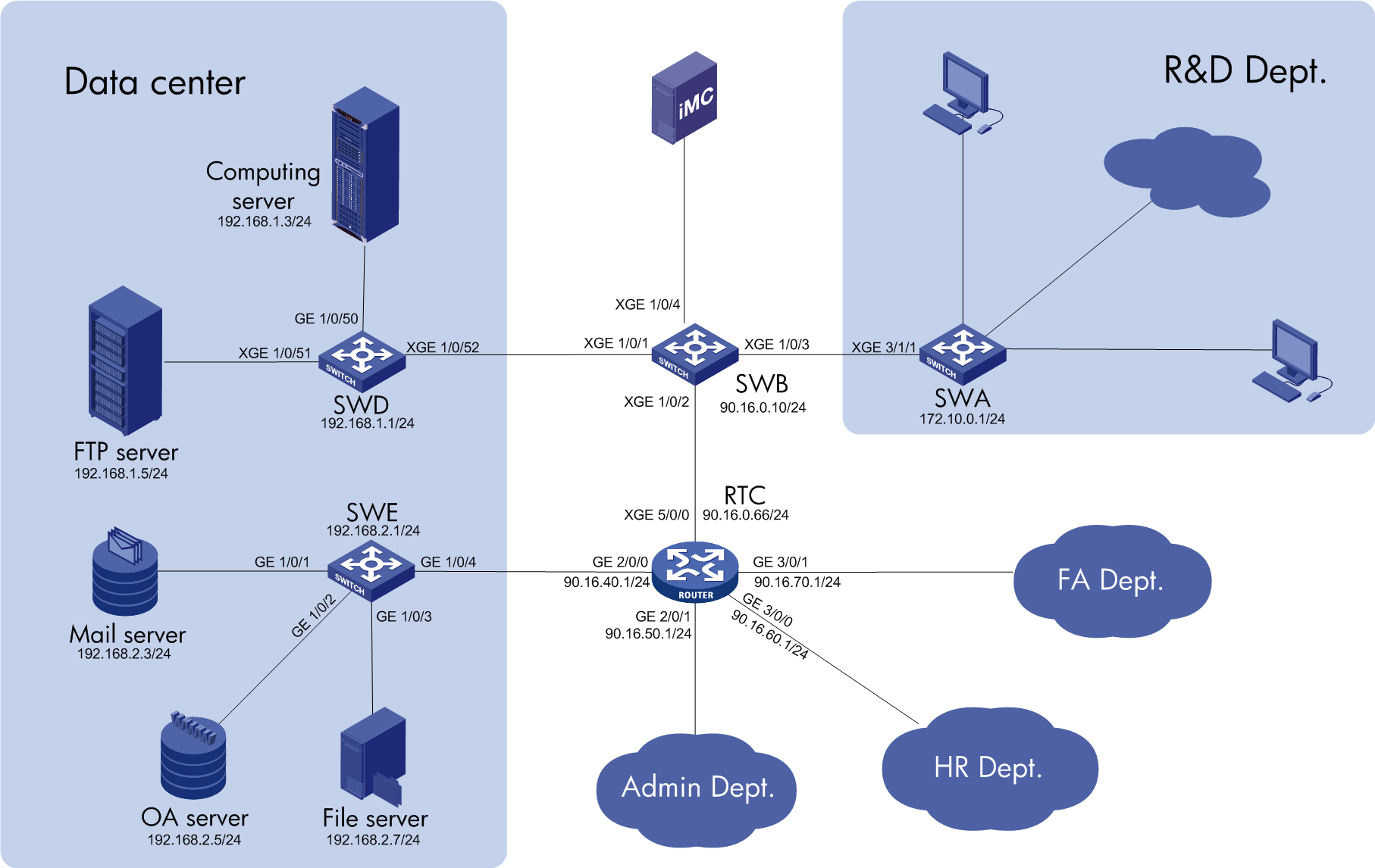
· Deny traffic from the Administration department, HR department, and Finance department to the computing server, but permit their traffic to the FTP server.
· Deny traffic from the R&D department to the file server but permit its traffic to the mail server and OA server.
· Deny traffic between the R&D department and all other departments.
· Limit the bandwidths for traffic from the FTP server to the Administration department, HR department, and Finance department to 50 Mbps each.
· The traffic from the computing server should have a higher priority to transmit on SWD.
Requirements analysis
· Deny packets with destination IP address 192.168.2.7 on XGE 3/1/1 of the SWA (172.10.0.1).
· Deny packets with destination IP addresses that belong to networks 90.16.50.1/24, 90.16.50.1/24, and 90.16.50.1/24 on XGE 3/1/1 of the SWA (172.10.0.1).
· Deny packets with destination IP address 192.168.1.3 on XGE 5/0/0 of the RTC (90.16.0.66).
· Deny packets with destination IP addresses that belong to network 172.10.0.0/24 on XGE 5/0/0 of the RTC (90.16.0.66).
· Limit the bandwidths to 50 Mbps for traffic with destination IP addresses that belong to networks 90.16.50.1/24, 90.16.50.1/24, or 90.16.50.1/24 on XGE 1/0/51 of the SWD (192.168.1.1).
· Set the interface priority of XGE 1/0/50 to 5 and set the interface priority of XGE 1/0/51 to 3 on SWD (192.168.1.1).
QoSM configuration analysis
This section lists the configuration tasks on QoSM:
· Add classifiers that match the traffic.
· Add behaviors to deny and police traffic.
· Add QoS policies that contain classifier-behavior associations.
· Import QoS policies to create QoS service.
· Add deployment tasks to deploy QoS configurations to interfaces of devices.
Configuration procedures
Adding classifiers
To access the classifier list page:
1. Click the Service tab.
2. From the navigation tree, select QoS Manager > QoS Resource > Classifier.
Adding a classifier to match the traffic from the R&D department to the file server
1. Click Add on the toolbar.
The Add QoS Classifier page appears.
2. Configure the following parameters, as shown in Figure 11:
¡ Name—Enter classifier name R&D-FileServer.
¡ Rule Relationship—Select and from the list.
¡ Select Behavior—Leave this field empty.
¡ IP Type—Select IPv4 from the list.
¡ Description—Enter a description for the classifier. As a best practice, include classifier characteristics in the description. This field can be blank.
¡ Select Model—Leave this field empty.
Figure 11 Configure basic information

3. Add a match rule for the classifier:
a. Click Add on the toolbar.
The Classifier Characteristics window appears.
b. Select Match IPv4 Address from the list of Type, and configure the following parameters, as shown in Figure 12:
- Name—Enter name R&D to File Server.
- State—Select Enabled from the list.
- Relation—Select =(match).
- IPv4 Source Address—Enter 172.10.0.0/24.
- IPv4 Destination Address—Enter 192.168.2.7.
c. Click OK.
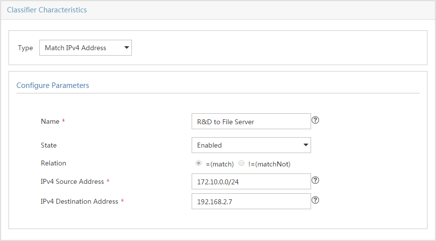
4. Click OK.
Adding a classifier to match the traffic from the R&D department to other departments
1. Click Add on the toolbar.
The Add QoS Classifier page appears.
2. Configure the following parameters, as shown in Figure 13:
¡ Name—Enter classifier name R&D-AdminDept.
¡ Rule Relationship—Select and from the list.
¡ Select Behavior—Leave this field empty.
¡ IP Type—Select IPv4 from the list.
¡ Description—Enter a description for the classifier. As a best practice, include classifier characteristics in the description. This field can be blank.
¡ Select Model—Leave this field empty.
Figure 13 Configure basic information

3. Add a match rule for the classifier:
a. Click Add on the toolbar.
The Classifier Characteristics window appears.
b. Select Match IPv4 Address from the list of Type, and configure the following parameters, as shown in Figure 14:
- Name—Enter name R&D to Admin.
- State—Select Enabled from the list.
- Relation—Select =(match).
- IPv4 Source Address—Enter 172.10.0.0/24.
- IPv4 Destination Address—Enter 90.16.50.0/24.
c. Click OK.

4. Click OK.
Add classifiers R&D-HR and R&D-FA in the same way, as shown in Figure 15 and Figure 16. Their match rules are named R&D to HR and R&D to FA, their IPv4 Destination Address are 90.16.60.0/24 and 90.16.70.0/24.
Figure 15 Match rule of R&D-HR

Figure 16 Match rule of R&D-FA
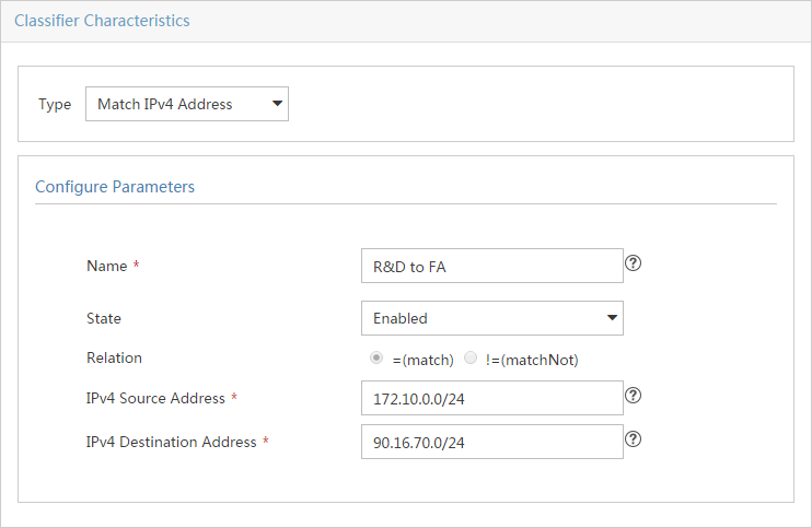
Adding a classifier to match the traffic from the non-R&D departments to the computing server
1. Click Add on the toolbar.
The Add QoS Classifier page appears.
2. Configure the following parameters, as shown in Figure 17:
¡ Name—Enter classifier name Admin-CptServer.
¡ Rule Relationship—Select and from the list.
¡ Select Behavior—Leave this field empty.
¡ IP Type—Select IPv4 from the list.
¡ Description—Enter a description for the classifier. As a best practice, include classifier characteristics in the description. This field can be blank.
¡ Select Model—Leave this field empty.
Figure 17 Configure basic information
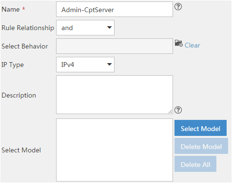
3. Add a match rule for the classifier:
a. Click Add on the toolbar.
The Classifier Characteristics window appears.
b. Select Match IPv4 Address from the list of Type, and configure the following parameters, as shown in Figure 18:
¡ Name—Enter name Admin to Computing Server.
- State—Select Enabled from the list.
- Relation—Select =(match).
- IPv4 Source Address—Enter 90.16.50.0/24.
- IPv4 Destination Address—Enter 192.168.1.3.
c. Click OK.
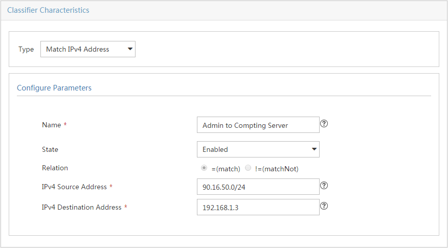
4. Click OK.
Add classifiers HR-CptServer and FA-CptServer in the same way, as shown in Figure 19 and Figure 20. Their match rules are named HR to Computing Server and FA to Computing Server, their IPv4 Source Address are 90.16.60.0/24 and 90.16.70.0/24.
Figure 19 Match rule of HR-CptServer

Figure 20 Match rule of FA-CptServer
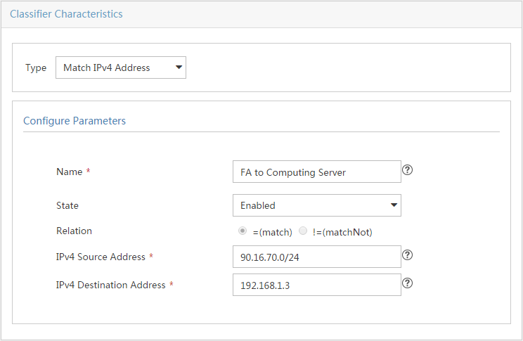
Adding a classifier to match the traffic from the non-R&D departments to the R&D department
1. Click Add on the toolbar.
The Add QoS Classifier page appears.
2. Configure the following parameters, as shown in Figure 21:
¡ Name—Enter classifier name Admin-R&D.
¡ Rule Relationship—Select and from the list.
¡ Select Behavior—Leave this field empty.
¡ IP Type—Select IPv4 from the list.
¡ Description—Enter a description for the classifier. As a best practice, include classifier characteristics in the description. This field can be blank.
¡ Select Model—Leave this field empty.
Figure 21 Configure basic information
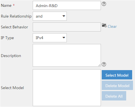
3. Add a match rule for the classifier:
a. Click Add on the toolbar.
The Classifier Characteristics window appears.
b. Select Match IPv4 Address from the list of Type, and configure the following parameters, as shown in Figure 22:
- Name—Enter name Admin to R&D.
- State—Select Enabled from the list.
- Relation—Select =(match).
- IPv4 Source Address—Enter 90.16.50.0/24.
- IPv4 Destination Address—Enter 172.10.0.0/24.
c. Click OK.

4. Click OK.
Add classifiers HR-R&D and FA-R&D in the same way, as shown in Figure 23 and Figure 24. Their match rules are named HR to R&D and FA to R&D, their IPv4 Source Address are 90.16.60.0/24 and 90.16.70.0/24.
Figure 23 Match rule of HR-R&D

Figure 24 Match rule of FA-R&D
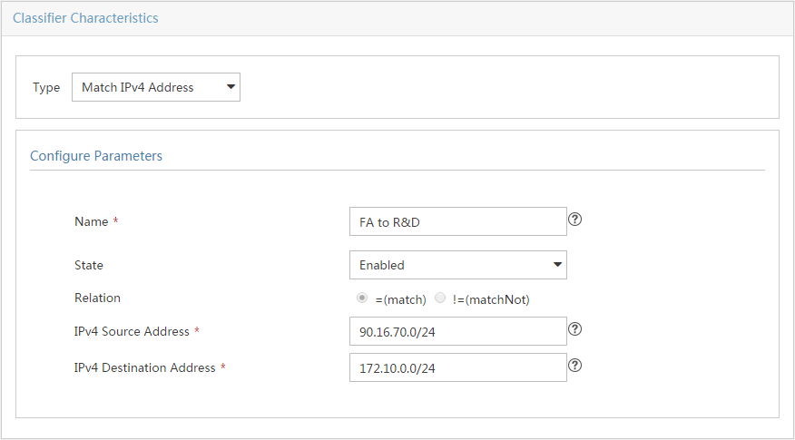
Adding a classifier to match the traffic from the FTP server to the non-R&D departments
1. Click Add on the toolbar.
The Add QoS Classifier page appears.
2. Configure the following parameters, as shown in Figure 25:
¡ Name—Enter classifier name FTPServer-Admin.
¡ Rule Relationship—Select and from the list.
¡ Select Behavior—Leave this field empty.
¡ IP Type—Select IPv4 from the list.
¡ Description—Enter a description for the classifier. As a best practice, include classifier characteristics in the description. This field can be blank.
¡ Select Model—Leave this field empty.
Figure 25 Configure basic information

3. Add a match rule for the classifier:
a. Click Add on the toolbar.
The Classifier Characteristics window appears.
b. Select Match IPv4 Address from the list of Type, and configure the following parameters, as shown in Figure 26:
- Name—Enter name FTP Server to Admin.
- State—Select Enabled from the list.
- Relation—Select =(match).
- IPv4 Source Address—Enter 192.168.1.2.
- IPv4 Destination Address—Enter 90.16.50.0/24.
c. Click OK.
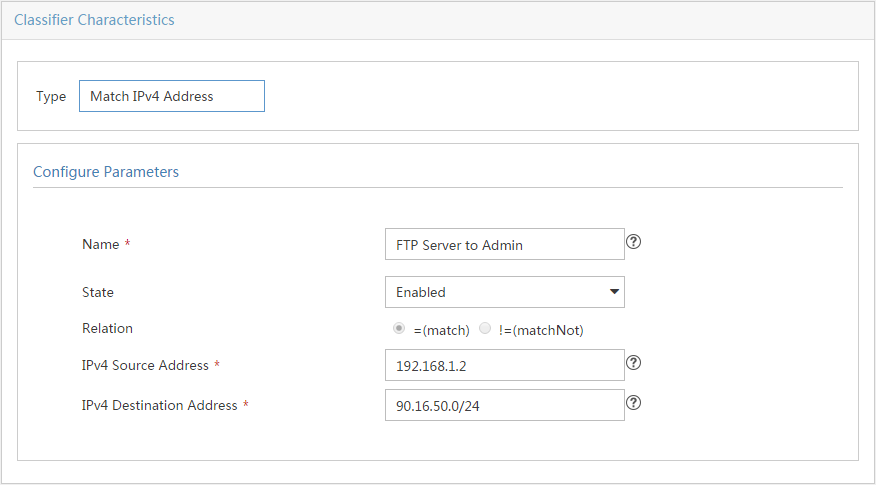
4. Click OK.
Add classifiers FTPServer-HR and FTPServer-FA in the same way, as shown in Figure 27 and Figure 28. Their match rules are named HR to R&D and FA to R&D, their IPv4 Destination Address are 90.16.60.0/24 and 90.16.70.0/24.
Figure 27 Match rule of FTPServer-HR

Figure 28 Match rule of FTPServer -FA
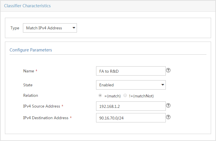
Adding behaviors
To access the behavior list page:
1. Click the Service tab.
2. From the navigation tree, select QoS Manager > QoS Resource > Behavior.
Adding behavior to deny traffic
1. Click Add on the toolbar.
The Add Behavior page appears.
2. Configure the following parameters, as shown in Figure 29:
¡ Name—Enter behavior name Deny.
¡ Description—Enter a description for the behavior. As a best practice, include features of behavior functions in the description. This field can be blank.
¡ Select Model—Leave this field empty.
Figure 29 Configure basic information

3. Select Deny from the list of Firewall, as shown in Figure 30.
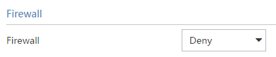
4. Click OK.
Adding a behavior to policing traffic
1. Click Add on the toolbar.
The Add Behavior page appears.
2. Configure the following parameters, as shown in Figure 31:
¡ Name—Enter behavior name CAR50M.
¡ Description—Enter a description for the behavior. As a best practice, include features of behavior functions in the description. This field can be blank.
¡ Select Model—Leave this field empty.
Figure 31 Configure basic information
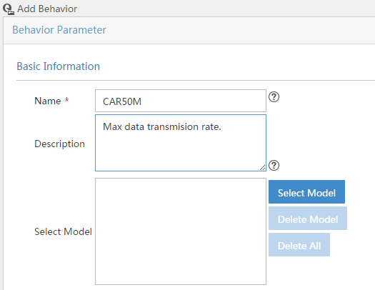
3. Click Config in the upper right corner of CAR.
The SetCAR page appears.
4. Configure the following parameters, as shown in Figure 32:
¡ CIR—Enter 50000.
¡ CIR—Click Recommend to use the system recommended value.
¡ Green Action—Select pass from the list.
¡ Yellow Action—Select discard from the list.
These parameters are enough to keep the transmission rate under 50Mbps. Leave the Advance Config empty.
Figure 32 Configure CAR parameters
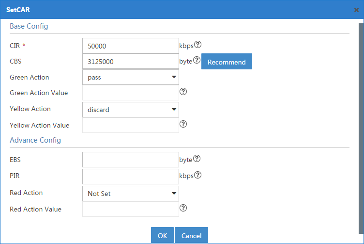
5. Click OK to return to the Add Behavior page.
6. Click OK.
Adding QoS Policies
To access the QoS policy list page:
1. Click the Service tab.
2. From the navigation tree, select QoS Manager > QoS Resource > QoS Policy.
Adding a QoS policy to deny the R&D department access to the file server and the non-R&D departments
1. Click Add on the toolbar.
The Add QoS Policy page appears.
2. Configure the following parameters, as shown in Figure 33:
¡ Name—Enter QoS policy name DenyR&DAccess.
¡ Description—Enter a description for the behavior. As a best practice, include QoS policy features in the description. This field can be blank.
¡ Select Model—Leave this field empty.
Figure 33 Configure basic information
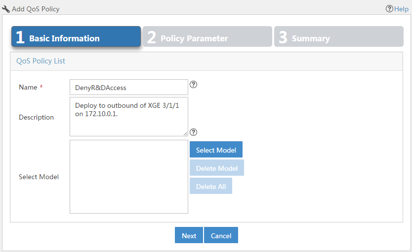
3. Click Next.
The Policy Parameter page appears, as shown in Figure 34.
4. Click the ![]() icon next to the Classifier field, and then select the classifier R&D-FileServer from the popup window.
icon next to the Classifier field, and then select the classifier R&D-FileServer from the popup window.
5. Click the ![]() icon next to the Behavior field, and then select the behavior Deny from the
popup window.
icon next to the Behavior field, and then select the behavior Deny from the
popup window.
6. Click Add.
The configured classifier-behavior association is added to the Classifier and Behavior Matching List.
7. Repeat step 4 through step 6 to add R&D-Admin—Deny, R&D-HR—Deny, and R&D-FA—Deny associations.
Figure 34 Add classifier-behavior associations
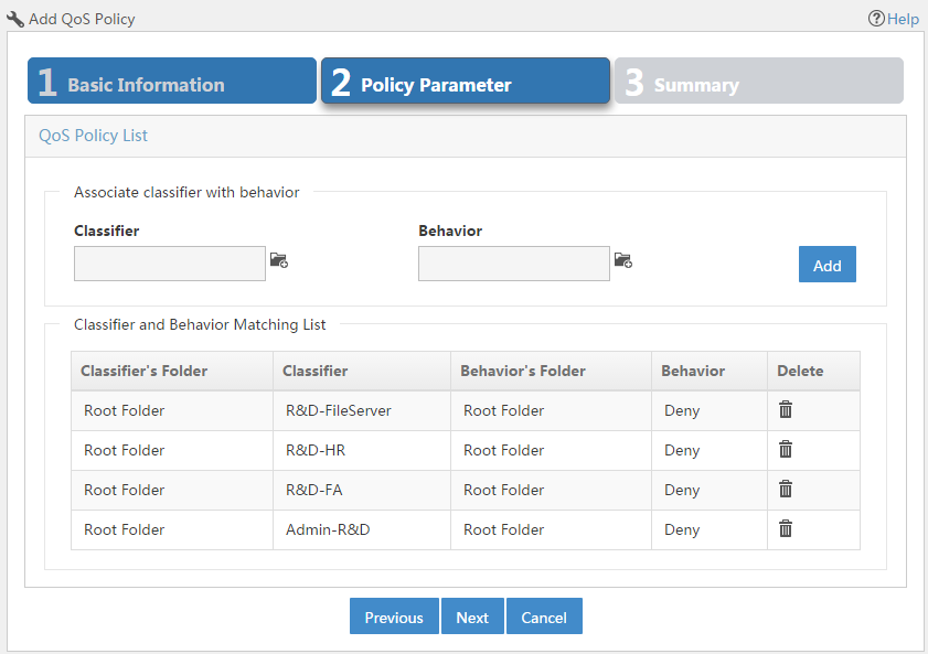
8. Click Next.
The Summary page appears.
9. Click OK.
Adding a QoS policy to deny non-R&D departments assess to the computing server and the R&D department
1. Click Add on the toolbar.
The Add QoS Policy page appears.
2. Configure the following parameters, as shown in Figure 35:
¡ Name—Enter QoS policy name DenyNon-R&D.
¡ Description—Enter a description for the QoS policy. As a best practice, include QoS policy features in the description. This field can be blank.
¡ Select Model—Leave this field empty.
Figure 35 Configure basic information
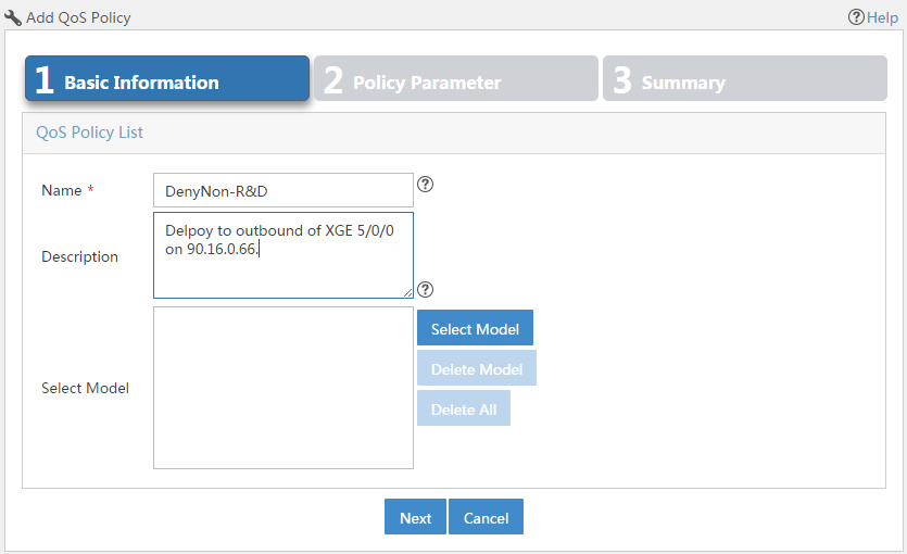
3. Click Next.
The Policy Parameter page appears, as shown in Figure 36.
4. Click the ![]() icon next to the Classifier field, and then select the classifier Admin-R&D from the popup window.
icon next to the Classifier field, and then select the classifier Admin-R&D from the popup window.
5. Click the ![]() icon next to the Behavior field, and then select the behavior Deny from the
popup window.
icon next to the Behavior field, and then select the behavior Deny from the
popup window.
6. Click Add.
The configured classifier-behavior association is added to the Classifier and Behavior Matching List.
7. Repeat step 4 through step 6 to add HR-R&D—Deny, FA-R&D—Deny, Admin-CptServer—Deny, HR-CptServer—Deny, and FA-CptServer—Deny associations.
Figure 36 Add classifier-behavior associations
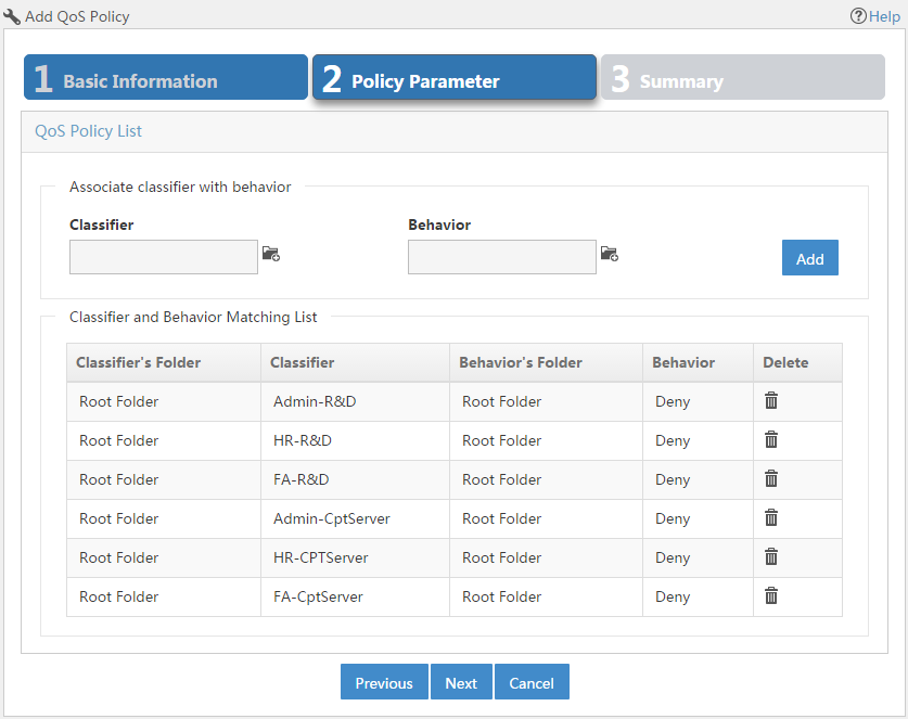
8. Click Next.
The Summary page appears.
9. Click OK.
Adding a QoS policy to limit bandwidth from the FTP server to non-R&D departments
1. Click Add on the toolbar.
The Add QoS Policy page appears.
2. Configure the following parameters, as shown in Figure 37:
¡ Name—Enter QoS policy name LimitFTPtoNon-R&D.
¡ Description—Enter a description for the QoS policy. As a best practice, include QoS policy features in the description. This field can be blank.
¡ Select Model—Leave this field empty.
Figure 37 Configure basic information
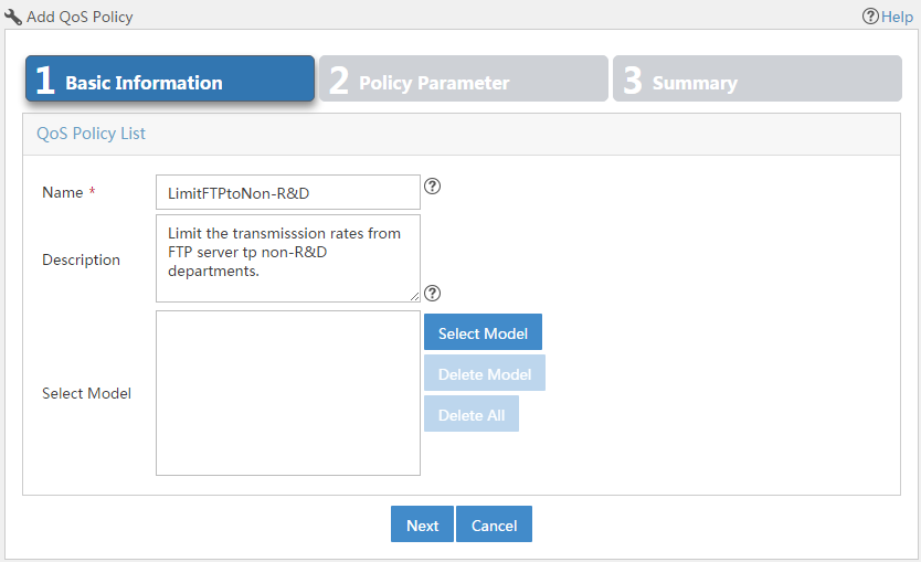
3. Click Next.
The Policy Parameter page appears, as shown in Figure 38.
4. Click the ![]() icon next to the Classifier field, and then select the classifier FTPServer-Admin from the popup window.
icon next to the Classifier field, and then select the classifier FTPServer-Admin from the popup window.
5. Click the ![]() icon next to the Behavior field, and then select the behavior CAR50M from the popup window.
icon next to the Behavior field, and then select the behavior CAR50M from the popup window.
6. Click Add.
The configured classifier-behavior association is added to the Classifier and Behavior Matching List.
7. Repeat step 4 through step 6 to add FTPServer-HR—CAR50M and FTPServer-FA—CAR50M associations.
Figure 38 Add classifier-behavior associations
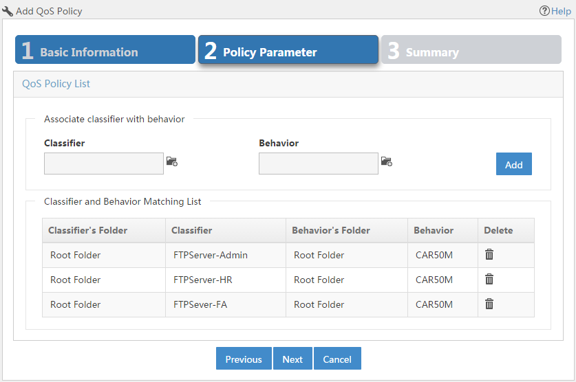
8. Click Next.
The Summary page appears.
9. Click OK.
Importing services
After the QoS policies are added, you must import QoS policies to create services.
1. Click the Service tab.
2. From the navigation tree, select QoS Manager > Business Deploy.
3. Click Import or the ![]() icon on the upper right corner of the
page.
icon on the upper right corner of the
page.
The Import the QoS policy as a service window appears, as shown in Figure 39.
4. Enter the service name DenyR&DAccess.
5. Enter a description for the service. As a best practice, include QoS service features in the description. This field can be blank.
6. Click the ![]() icon next to the Select
QoS policy field, select
the QoS policy DenyR&DAccess from the
popup window.
icon next to the Select
QoS policy field, select
the QoS policy DenyR&DAccess from the
popup window.
Figure 39 Import the QoS policy as a service
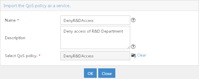
7. Click OK.
8. Repeat step 3 through step 7 to import the service DenyNon-R&D and LimitFTPtoNon-R&D, as shown in Figure 40 and Figure 41.
Figure 40 Import the QoS policy as a service
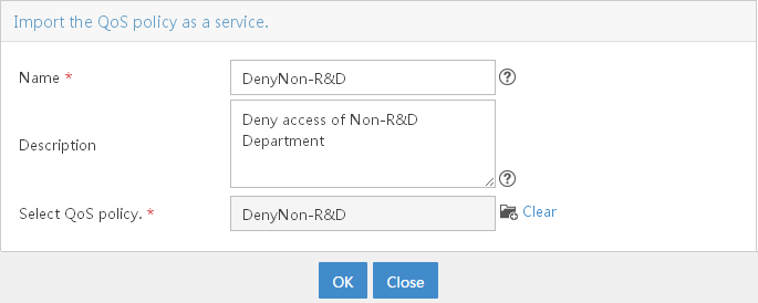
Figure 41 Import the QoS policy as a service
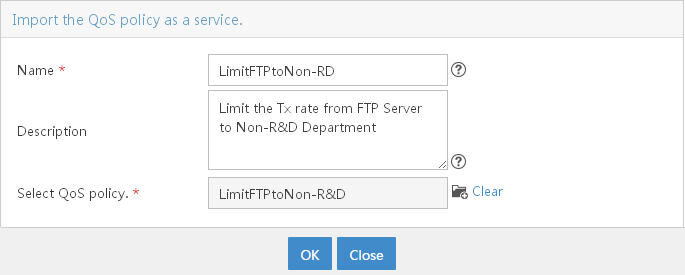
Adding deployment tasks
Adding an MQC deployment task to deny the R&D department access to the file server and non-R&D departments
1. Click the Service tab.
2. From the navigation tree, select QoS Manager > Deploy Task.
3. Click Add on the toolbar.
The Deploy Guide page appears.
4. In the Apply Policy to Interface area, click Select Device.
5. Select S5500 (172.10.0.1) switch from the popup window.
6. Click the Select Device Interface icon ![]() in the Number of
interfaces (outbound direction) column.
in the Number of
interfaces (outbound direction) column.
7. Select Ten-GigabitEthernet3/1/1 from the popup window.
8. Click Next.
The Setting QoS Policy page appears, as shown in Figure 42.
9. Select DenyR&DAccess from the list of Select service.
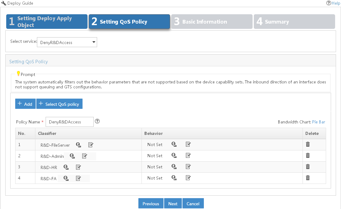
10. Click Next.
The Basic Information page appears.
11. Configure the following parameters:
¡ Task Name—Enter the task name Deny R&D Access.
¡ For the policy deployed—Select Overwrite.
¡ Predefined Execution Time—Select Immediately.
¡ Task Description—Enter a description for the task.
12. Click Next.
The Summary page appears.
13. Click Finish.
Adding an MQC deployment task to deny non-R&D departments access to the computing server and the R&D department
1. Click the Service tab.
2. From the navigation tree, select QoS Manager > Deploy Task.
3. Click Add on the toolbar.
The Deploy Guide page appears.
4. In the Apply Policy to Interface area, click Select Device.
5. Select SR6608 (90.16.0.66) router from the popup window.
6. Click the Select Device Interface icon ![]() in the Number of
interfaces (outbound direction) column.
in the Number of
interfaces (outbound direction) column.
7. Select Ten-GigabitEthernet5/0/0 from the popup window.
8. Click Next.
The Setting QoS Policy page appears, as shown in Figure 43.
9. Select DenyNon-R&D from the list of Select service.
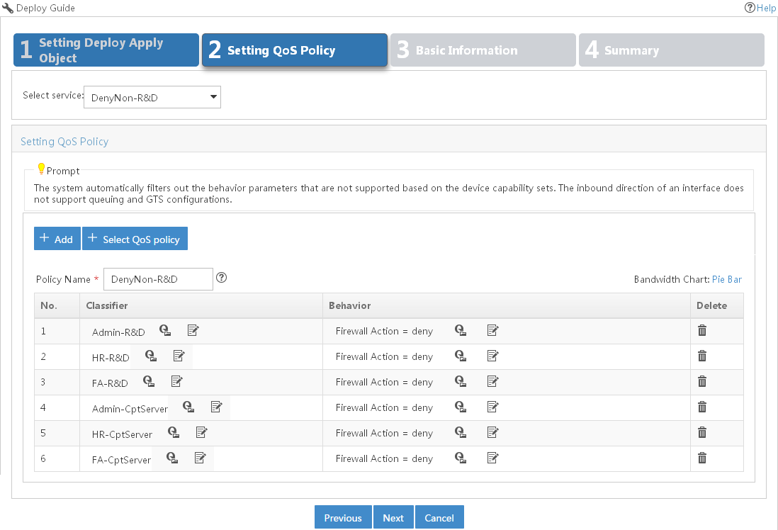
10. Click Next.
The Basic Information page appears.
11. Configure the following parameters:
¡ Task Name—Enter task name Deny Non-R&D Access.
¡ For the policy deployed—Select Overwrite.
¡ Predefined Execution Time—Select Immediately.
¡ Task Description—Enter a description for the task.
12. Click Next.
The Summary page appears.
13. Click Finish.
Adding an MQC deployment task to limit the bandwidth from the FTP server to non-R&D departments
1. Click the Service tab.
2. From the navigation tree, select QoS Manager > Deploy Task.
3. Click Add on the toolbar.
The Deploy Guide page appears.
4. In the Apply Policy to Interface area, and then click Select Device.
5. Select SWD (192.168.1.1) switch from the popup window.
6. Click the Select Device Interface icon ![]() in the Number of
interfaces (outbound direction) column.
in the Number of
interfaces (outbound direction) column.
7. Select Ten-GigabitEthernet1/0/51 from the popup window.
8. Click Next.
The Setting QoS Policy page appears.
9. Select LimitFTPtoNon-RD from the list of Select service, as shown in Figure 44.
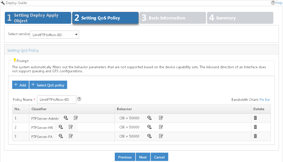
10. Click Next.
The Basic Information page appears.
11. Configure the following parameters:
¡ Task Name—Enter task name LimitTxRateFTPtoNonRD.
¡ For the policy deployed—Select Overwrite.
¡ Predefined Execution Time—Select Immediately.
¡ Task Description—Enter a description for the task.
12. Click Next.
The Summary page appears.
13. Click Finish.
Adding a non-MQC deployment task
Assign priority for the traffic from the computing server and FTP server. The computing server accesses the network through the Ten-GigabitEthernet1/0/50 of SWD. The FTP server accesses the network through the Ten-GigabitEthernet1/0/51 of SWD. On SWD, set the interface priority of the Ten-GigabitEthernet1/0/50 interface to 5, and configure the priority of the Ten-GigabitEthernet1/0/51 interface to 3.
1. Click the Service tab.
2. From the navigation tree, select QoS Manager > QoS Device.
The QoS Device page appears.
3. Click the Operation
icon ![]() for the SWD, and then
select QoS Configuration Info from the menu.
for the SWD, and then
select QoS Configuration Info from the menu.
The QoS Configuration Info page appears.
4. Clear the Display only interfaces with CBQ deployed box.
5. Click the Configure link in the Interface Configuration column for Ten-GigabitEthernet1/0/50.
6. Click Next.
The Set GTS, Priority, and Software Queuing page appears, as shown in Figure 45.
7. Select Configure from the list of Configure or Not in Priority field.
8. Select 802.1p priority and set its value to 5.
Figure 45 Configure interface priority
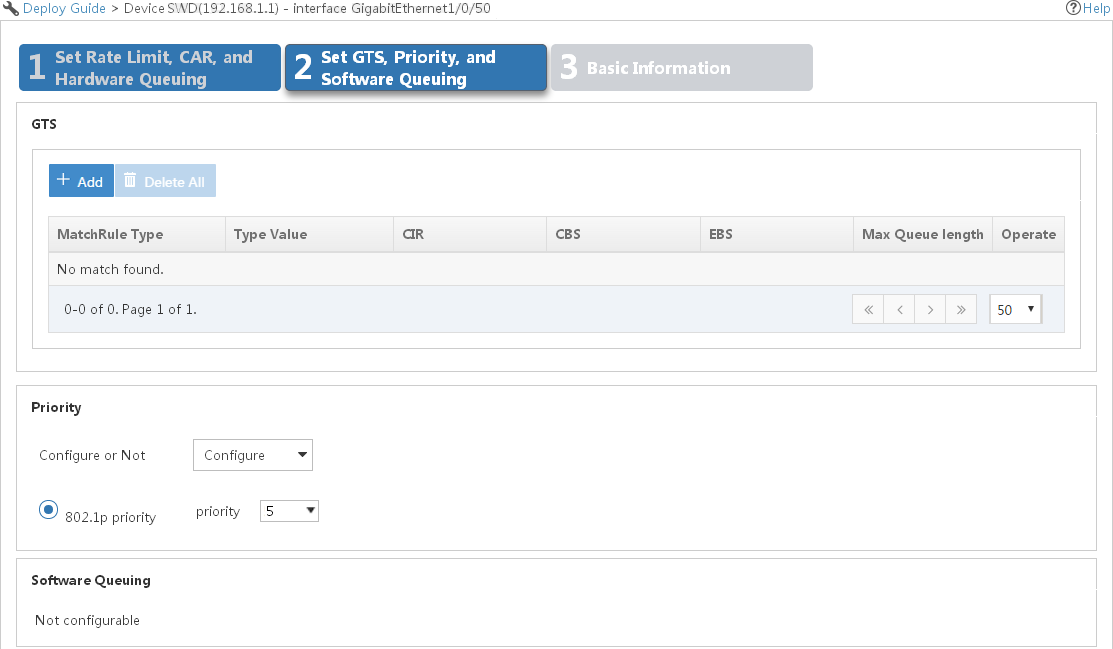
9. Click Next.
The Basic Information page appears.
10. Configure the following parameters, as shown in Figure 46:
¡ Task Name—Enter task name ConfigureDot1p5.
¡ For the policy deployed—Select Overwrite.
¡ Predefined Execution Time—Select Immediately.
¡ Task Description—Enter a description for the task.
11. Click Finish.
Configure the priority of the Ten-GigabitEthernet1/0/51 interface to 3 in the same way. Its task name is ConfigureDot1p3.
Figure 46 Configure interface priority

Verifying the configuration
Viewing the deployment result
View the deployment result in the Deploy Task page. The following procedure uses the temporary department as an example to show the deployment result.
1. Click the Service tab.
2. From the navigation tree, select QoS Manager > Deploy Task.
The deployment task list appears, as shown in Figure 47.
3. All deployment tasks are successfully deployed.
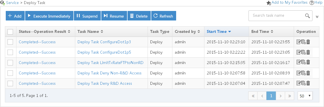
Verifying the configuration
Verifying the connectivity between the R&D department and other departments and the file server
The R&D department's client uses the IP address 172.10.0.21 and connects to SWA. Use the R&D department client to ping hosts of the non-R&D department and file server. The results of ping operations are Request timed out. See Figure 48.
Figure 48 Connectivity between R&D department and other departments/file server
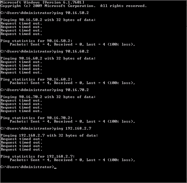
Verifying the connectivity between the non-R&D department and the computing server
From the computing server, ping the hosts of the non-R&D department. The results of ping operations are Request timed out. See Figure 49.
Figure 49 Connectivity between non-R&D department and Computing server