- Table of Contents
- Related Documents
-
| Title | Size | Download |
|---|---|---|
| 01-Text | 4.61 MB |
Examining the installation site
Installing the switch in a 19-inch rack
Mounting brackets and rack mounting rail kit
Rack-mounting procedures at a glance
Attachingthe mounting brackets, chassis rails, and grounding cableto the chassis
Attaching the slide rails to the rack
Mounting the switch in the rack
Grounding the switch with a grounding strip
Grounding the switch by using the AC power cord
Installing/removing a fan tray
Installing/removinga power module
Accessing the switch for the first time
Setting up the configuration environment
Planning IRF fabric size and the installation site
Identifying the master switch and planning IRF member IDs
Planning IRF topology and connections
Identifying physical IRF ports on the member switches
Configuring basic IRF settings
Connecting the physical IRF ports
Accessing the IRF fabric to verify the configuration
Maintenance and troubleshooting
Configuration terminal problems
Appendix A Chassis views and technical specifications
Appendix B FRUs and compatibility matrixes
1/10GBase-T autosensing Ethernet port
1/10GBase-T autosensing Ethernet port LEDs
Preparing for installation
Safety recommendations
To avoid any equipment damage or bodily injury, read the following safety recommendations before installation. Note that the recommendations do not cover every possible hazardous condition.
· Before cleaning the switch, unplugall power cordsfromthe switch. Do not clean the switch with wet cloth or liquid.
· Do not place the switch near water or in a damp environment. Prevent water or moisture from entering the switch chassis.
· Do not place the switch on an unstable case or desk. The switch might be severely damaged in case of a fall.
· Ensure goodventilation of the equipment room and keep the air inlet and outlet vents of the switch free of obstruction.
· Make sure the operating voltage is in the required range.
· To avoid electrical shocks, do not open the chassis while the switch is operating or when the switch is just powered off.
· When replacing FRUs,including power modules and fan trays, wear an ESDwrist strap to avoid damaging the units.
Examining the installation site
The switch must be used indoors.
Mount your switch in a rack and make sure:
· Adequate clearance is reserved at the air inlet and exhaust vents for ventilation.
· The rack has a good ventilation system.
· Identify the hot aisle and cold aisle at the installation site, and make sureambient air flows into the switch from the cold aisle and exhausts to the hot aisle.
· Identify the airflow designs of neighboring devices, and prevent hotair flowing out of the bottom device from entering thetop device.
· The rack is sturdy enough to support the switchand its accessories.
· The rack is correctly grounded.
To ensure normal operation and long service life of your switch, install it in an environment that meets the requirements described in the following subsections.
Temperature/humidity
Maintain appropriate temperature and humidity in the equipment room.
· Lasting high relative humidity can cause poor insulation, electricity leakage, mechanical property change of materials, and metal corrosion.
· Lasting low relative humidity can cause washer contraction and ESD and bring problems including loose mountingscrews and circuit failure.
· High temperature can accelerate the aging of insulation materials and significantly lower the reliability and lifespan of the switch.
For the temperature and humidity requirements of different switch models, see"Technical specifications."
Cleanliness
Dust buildup on the chassis might result in electrostatic adsorption, which causes poor contact of metal components and contact points, especially when indoor relative humidity is low. In the worst case, electrostatic adsorption can cause communication failure.
Table 1 Dust concentration limit in the equipment room
|
Substance |
Concentration limit (particles/m³) |
|
Dust |
≤ 3 x 10⁴ (no visible dust on the tabletop over three days) |
|
NOTE: Dust diameter ≥ 5 μm |
|
The equipment room must also meet limits on salts, acids, and sulfides to eliminate corrosion and premature aging of components, as shown inTable 2.
Table 2 Harmful gas limits in the equipment room
|
Gas |
Maximum concentration (mg/m3) |
|
SO2 |
0.2 |
|
H2S |
0.006 |
|
NH3 |
0.05 |
|
Cl2 |
0.01 |
EMI
Electromagnetic interference (EMI) might be coupled from the source to the switch through the following coupling mechanisms:
· Capacitive coupling
· Inductive coupling
· Radiative coupling
· Common impedance coupling
· Conductive coupling
To prevent EMI, usethe following guidelines:
· If AC power is used, use a single-phase three-wire power receptacle with protection earth (PE) to filter interference from the power grid.
· Keep the switch far away from radio transmitting stations, radar stations, and high-frequency devices.
· Use electromagnetic shielding, for example, shielded interface cables, when necessary.
· To prevent signal ports from getting damaged by overvoltage or overcurrent caused by lightning strikes, route interface cables only indoors.
Laser safety
|
|
WARNING! Do not stare into any fiber port when the switch has power. The laser light emitted from the optical fiber might hurt your eyes. |
The switch is aClass 1 laser device.
Installation tools
The installation tools are not provided with the switch. Prepare them yourself.
· Phillips screwdriver
· ESD wrist strap
Installing the switch
|
|
CAUTION: Keep the tamper-proof seal on a mounting screw on the chassis cover intact, and if you want to open the chassis, contact H3Cfor permission. Otherwise, H3Cshall not be liable for any consequence caused thereby. |
Figure 1 Hardware installation flow
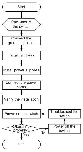
Installing the switch in a 19-inch rack
Installation prerequisites
To close the rack door easily, make sure the rack depth for the S6300-42QTswitchisa minimum of 1000 mm (39.37 in).
The distance from the front to the rear posts of the rack must meet the requirements described in Table 3.
You must use both the mounting bracket and the rack mounting rail kit to rack-mount the switch.
Table 3 Requirements for the distance from the front to rear posts
|
Switch model |
Installation method |
Minimum distance |
Maximum distance |
|
· S6300-42QF · S6300-48S · S6300-52QF |
Using mounting brackets and short slide rails (supplied with the switch) |
401 mm (15.79 in) |
654 mm (25.75 in) |
|
Using mounting brackets and long slide rails(optional) |
621 mm (24.45 in) |
874 mm (34.41 in) |
|
|
S6300-42QT |
Using mounting brackets and short slide rails (supplied with the switch) |
405 mm (15.94 in) |
854 mm (33.62in) |
Mounting brackets and rack mounting rail kit
The switch comes with a pair of mounting brackets (see Figure 2) and a rack mounting kit that includesa pair of chassis railsand a pair of slide rails (see Figure 3).
Figure 2 1U mounting bracket kit
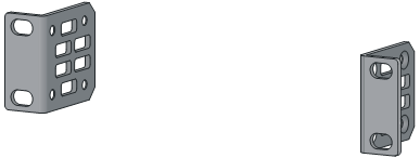
Figure 3 Rack mounting rail kit
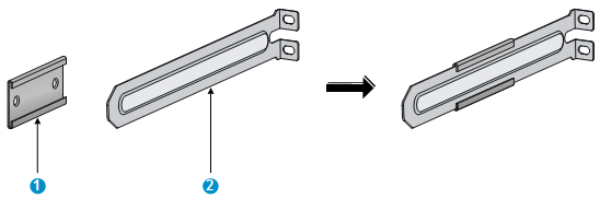
|
(1) Chassis rail |
(2) Slide rail |
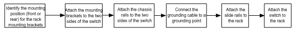
Rack-mounting procedures at a glance
Figure 4 Rack-mounting procedure
|
|
NOTE: If a rack shelf is available, you canput the switch on the rack shelf, slide the switch to an appropriate location, and attach the switch to the rack with the mounting brackets. |
Attachingthe mounting brackets, chassis rails, and grounding cableto the chassis
The switchhasone front mounting position (near the network ports) and one rear mounting position (near the power modules).
The switch hasone primary grounding point (with a grounding sign)and two auxiliary grounding points. Use the primary grounding point whenever possible. If the primary grounding point fails or is not suitable for the installation site, use one of the auxiliary grounding points.
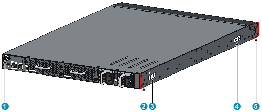
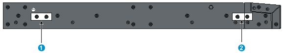
Figure 5 Mounting and grounding positions of the S6300-42QT
|
(1) Auxiliary grounding point 2 |
(2) Rear mounting position |
|
(3) Primary grounding point |
(4) Auxiliary grounding point 1 |
|
(5) Front mounting position |
|
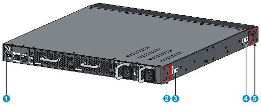
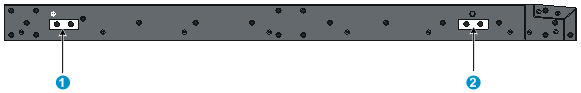
Figure 6 Mounting and grounding positions of the S6300-42QF/S6300-48S/S6300-52QF
|
(1) Auxiliary grounding point 2 |
(2) Rear mounting position |
|
(3) Primary grounding point |
(4) Auxiliary grounding point 1 |
|
(5) Front mounting position |
|
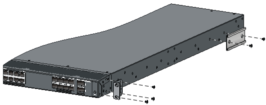
Attaching the mounting brackets and chassis rails to the chassis
1. Align the mounting brackets with the screw holes in the rear mounting position (see Figure 7) or front mounting position (seeFigure 8).
2. Use M4 screws (supplied with the switch) to attach the mounting brackets to the chassis.
3. Align the chassis rails with the rail mounting holes in the chassis:
¡ If the mounting brackets are in the rear mounting position, align the chassis rails with the screw holes at the front of the side panels (see Figure 7).
¡ If the mounting brackets are in the front mounting position, align the chassis rails with the screw holes at the rear of the side panels (seeFigure 8).
4. Use M4 screws (supplied with the switch) to attach the chassis rails to the chassis.
|
|
NOTE: Secure the mounting brackets and chassis rails to both sides of the chassis in the same way. |
Connecting the grounding cable to the chassis
|
|
CAUTION: The primary grounding point and auxiliary grounding point 1 are located on the left side panel. If you use one of these grounding points, you must connect the grounding cable to the grounding point before youmountthe switch inthe rack. |
Toconnect the grounding cable toa chassis grounding point, for example, the primary grounding point:
1. Choose a grounding point.
2. Unpack the grounding cable and grounding screws.
3. Align the two-hole grounding lug at one end of the cable with the grounding holes of the grounding point, insert the grounding screws into the holes, and tighten the screws with a screwdriver to attach the grounding lug to the chassis, as shown in Figure 7.
Figure 7 Attachingthe rear mounting brackets/chassis rails/grounding cable to the chassis
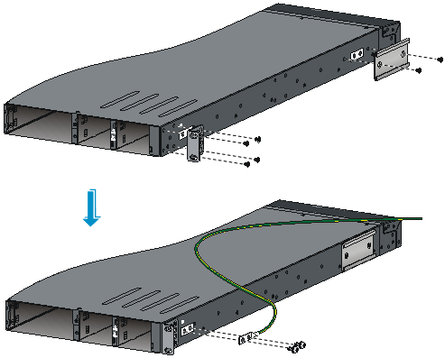
Figure 8 Attachingthe front mounting brackets/chassis rails to the chassis
|
|
NOTE: As a best practice,use the primary grounding point or auxiliary grounding point 1 because the grounding cable and grounding screw that come with the switch are suitable only forthese two grounding points. |
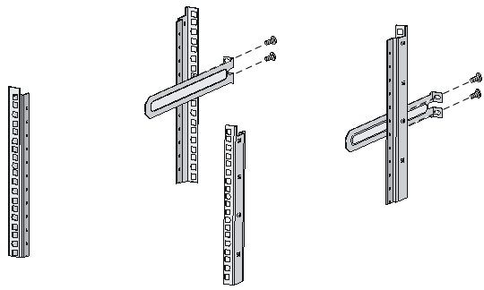
Attaching the slide rails to the rack
1. Identify the rack attachment position for the slide rails, and mark cage nut installation positions on the rack posts.
2. Install cage nuts(user-supplied)in the mounting holes in the rack posts.
3. Align the screw holes inone slide rail with the cage nuts in the rack post on one side, and use screws (user supplied) to attach the slide rail to the rack, as shown in Figure 9.
4. Repeat the preceding step to attach the other slide rail to the rack post on the other side.
Keep the two slide rails at the same height so the slide rails can attachinto the chassis rails.
Figure 9 Installing the slide rails
Mounting the switch in the rack
This task requires two people.
To mount the switch in the rack:
1. Wear an ESD wrist strap and make sure it makes good skin contact and is well grounded.
2. Verifythat the mounting brackets and chassis rails have been securely attached to the switch chassis.
3. Verifythat the slide rails have been correctly attached to the rear rack posts.
4. Install cage nuts (user-supplied)to the front rack posts and make sure they are at the same levelas the slide rails.
5. Supporting the bottom of the switch, align the chassis rails with the slide rails on the rack posts, as shown inFigure 10.Work with another person to slide the chassis rails along the slide rails until the mounting brackets are flush with the rack posts.
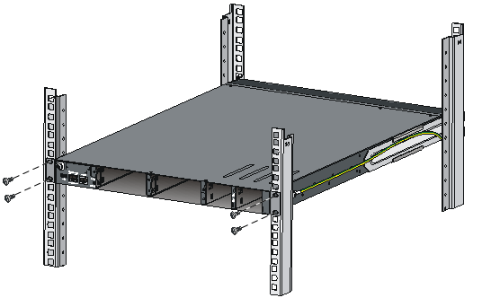
6. Use screws (user-supplied) to attach the mounting brackets to the rack, as shown in Figure 11.
To secure the switch in the rack, make sure the front ends of the slide rails reach out of the chassis rails.
Figure 10 Mounting the switch in the rack (1)
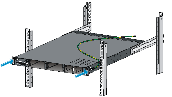
Figure 11 Mounting the switch in the rack (2)
Grounding the switch
|
|
WARNING! Correctly connecting the switch grounding cableis crucial to lightning protection and EMI protection. |
The power input end of the switch has a noise filter, whose central ground is directly connected to the chassis to form the chassis ground (commonly known as PGND).You must securely connect this chassis ground to the earth so the faradism and leakage electricity can be safely released to the earth to minimize EMIsusceptibility of the switch.
You can ground a switch by using a grounding strip at the installation site or the AC power cord connected to the switch.
|
|
NOTE: The power and grounding terminals in this section are for illustration only. |
Grounding the switch with a grounding strip
|
|
WARNING! Connect the grounding cable to the grounding system in the equipment room. Do not connect it to a fire main or lightning rod. |
If a grounding strip is available at the installation site, connect the grounding cable to the grounding strip.
To connect the grounding cable:
1. Attach the two-hole grounding lug at one end of the grounding cable to a grounding point onthe switchchassis (see "Connecting the grounding cable to the chassis").
2. Remove the hex nut ofa grounding post on the grounding strip.
3. Attach the ringterminal at the other end of thegrounding cable to the grounding strip through thegrounding post, and fasten the ringterminalwiththe removedhex nut.
Figure 12 Connecting the grounding cable to a grounding strip
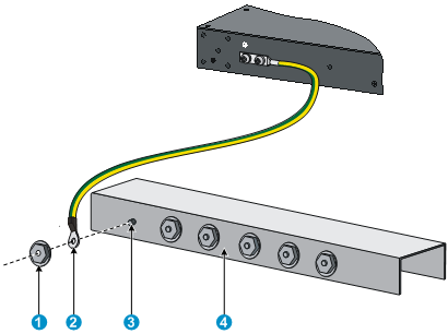
|
(1) Hex nut |
(2) Ringterminal |
|
(3) Grounding post |
(4) Grounding strip |
|
|
NOTE: · As a best practice,use the primary grounding point or auxiliary grounding point 1, because the grounding cable and grounding screw provided with the switch are applicable only to these two grounding points. · To useauxiliary grounding point 2 on the switch, prepare a grounding cable yourself.The connection method is the same as connecting to the other two grounding points. |
Grounding the switch by using the AC power cord
If the installation site has no grounding strips, you can ground an AC-powered switch through the protective earth (PE) wire of the power cord, but must make sure:
· The power cordhas a PE terminal.
· The ground contact in the power outlet is securely connected to the ground in the power distribution room or on the AC transformer side.
· The power cord is securely connected to the power outlet.
|
|
NOTE: If the ground contact in the power outlet is not connected to the ground, report the problem and reconstruct the grounding system. |
Figure 13 Grounding through the PE wire of the AC power cord
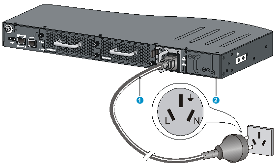
|
(1) Three-wire AC power cable |
(2) Chassis rear panel |
|
|
NOTE: To guarantee the grounding effect, use the grounding cable provided with the switch to connect to the grounding strip in the equipment room as long as possible. |
Installing/removing a fan tray
|
|
CAUTION: To ensure good ventilation for the switch: · Install two fan trays of the same model on the switch. · Do not operate the system with one failed fan tray for more than 24 hours. · Do not remove the failed fan tray until you are ready for replacing it. · Do not operate the system without any fan tray for more than 2 minutes. · Do not operate the system outside of the temperature range 0°C to 45°C (32°F to 113°F) degrees. |
Installing a fan tray
|
|
CAUTION: To prevent damage to the fan tray or the connectors on the backplane, insert the fan tray gently. If you encounter a hard resistance while inserting the fan tray, pull out the fan tray and insert it again. |
Select appropriate fan trays as needed. For the optional fan trays and their specifications, see "Fan trays."
To install a fan tray:
1. Wear an ESD wrist strap and make sure it makes good skin contact and is well grounded.
2. Unpack the fan tray and verifythat the fan tray model is correct.
3. Grasp the handle of the fan tray with one hand and supportthe fan tray bottom with the other, and slide the fan tray along the guide rails into the slot until the fan tray seats in the slot and has a firm contact with the backplane (see callout 1 in Figure 14).
4. Fasten the captive screw on the fan tray with a Philips screwdriver until the fan tray is securely attached in the chassis (see callout 2 in Figure 14).
If the captive screw cannot be tightly fastened, verify the installation of the fan tray.
Figure 14 Installing an LSWM1FANSC/LSWM1FANSCB/LSWM1HFANSC/LSWM1HFANSCB fan tray(on the S6300-52QF)
Removing a fan tray
|
|
WARNING! · Take out the fan tray after the fans completely stop rotating. · To avoid an unbalanced fan causing loud noise, do not touch the fans, even if they are not rotating. |
To remove a fan tray:
1. Wear an ESD wrist strap and make sure it makes good skin contact and is well grounded.
2. Loosen the captive screw of the fan tray with a Philips screwdriveruntil it is fully disengaged from the switch chassis.
3. Grasp the handle of the fan tray with one hand and pull thefan traypart way out the slot. Supportthe fan tray bottom with the other hand, and pull the fan tray slowly along the guide rails out of the slot.
4. Put away the removed fan tray in an antistatic bag for future use.
Installing/removinga power module
|
|
WARNING! In power redundancy mode, you can replace a power module without powering off the switch but must strictly follow the installation and procedures inFigure 15 and Figure 16 to avoid any bodily injury or damage to the switch. |
Theswitchcomes with both power module slots empty and the power filler modules as accessories.
You can installone or two power modules for these switches as needed. For more informationabout thepower modules available for the switches, see"Power modules."
Figure 15 Installation procedure
![]()
![]()
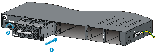
Installingapower module
|
|
CAUTION: · Follow the forward inertia of the power module when inserting it into the chassis, and make sure the power module has firm contact with the connectors on the backplane. · To prevent damage to the connectors inside the switch chassis, insert the power module gently. If you encounter a hard resistance while inserting the power module, pull out the power module and insert it again. · If only one power module is installed, install a power filler module in the empty power module slot for good ventilation of the switch. |
To install anLSVM1AC300, LSVM1DC300, LSVM1AC650,or LSVM1DC650power moduleintothe switch:
1. Wear an ESD wrist strap and make sure it makes good skin contact and is well grounded.
2. Unpack the power module and verifythat the power module model is correct.
3. Correctly orient the power module with the power module slot (see Figure 17),grasp the handle of the power modulewith one hand and supportits bottom with the other, and slide the power moduleslowly along the guide rails into the slot.
The slot is foolproof. If you cannot insert the power module into the slot, re-orient the power module rather than use excessive force to push it in.
Figure 17 Installing a power module
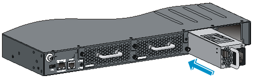
Figure 18 Installing a power filler module
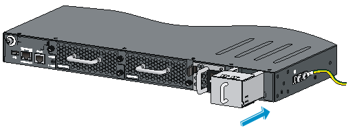
Removing apower module
|
|
CAUTION: If the switch has two power modules, removing one power module does not affect the operation of the switch. If the switch has only one power module, removing the power module powers off the switch. |
To remove anLSVM1AC300, LSVM1DC300, LSVM1AC650,or LSVM1DC650power modulefrom theswitch:
1. Wear an ESD wrist strap and make sure it makes good skin contact and is well grounded.
2. Squeeze the tabs on the power cord connector with your thumb and forefinger, and pull the connector out to remove the power cord, as shown in Figure 19.
3. Hold the handle on the power module with one hand, pivot the latch on the power module to the right with your thumb, and pull thepower modulepart way out of the slot, as shown in Figure 20.
4. Supporting the power module bottom with one hand, slowly pull thepower module out with the other hand.
5. Put away the removed power module in an antistatic bag for future use.
Figure 19 Removingthe DC power cord
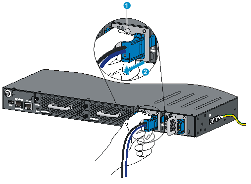
|
(1) Press the tabs on the power cord connector with your thumb and forefinger |
|
(2) Pull the power cord connector out |
Figure 20 Removing the power module
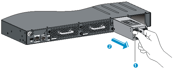
|
(1) Pivot the latch to the right with your thumb |
(2) Pull the power module out |
Connecting the power cord
Connecting theAC power module
1. Insert the female connector of the AC power cordsuppliedwith the power module into the power receptacleon the power module.
2. Use a cable tie to secure the power cord to the handle of the power module, as shown in Figure 21.
3. Connect the other end of the power cord to an AC power outlet.
Figure 21 ConnectingtheLSVM1AC300or LSVM1AC650power module on the S6300-52QF switch
|
(1) Cable tie |
|
(2) Tighten the cable tie to secure the power cord to the handle of the power module |
Connecting theDC power module
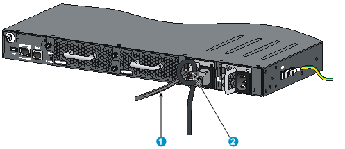
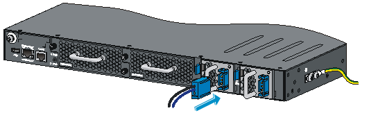
1. Unpack the DC power cord, identify the plug for connecting to the power module, orient the plug with the power receptacle on the power module, and insert the plug into the receptacle (see Figure 22).
The receptacle is foolproof. If you cannot insert the plug into the receptacle, re-orient the plug rather than use excessive force to push it in.
2. Use a cable tie to secure the power cord to the handle of the power module, as shown in Figure 21.
3. Connect the other end of the power cord to the DC power source.
Figure 22 ConnectingtheLSVM1DC300 or LSVM1DC650power module on the S6300-52QF
Verifying the installation
After you complete the installation, verify that:
· There is enough space for heat dissipation around the switch, and the rack is stable.
· The grounding cable is securely connected.
· The correctpower source is used.
· The power cords are correctly connected.
· All the interface cables are cabled indoors. If any cable is routed outdoors, verify that the socket strip with lightning protection and lightning arresters for network ports have been correctly connected.
Accessing the switch for the first time
Setting up the configuration environment
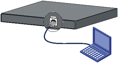
The first time you access the switch you must use a console cable to connect a console terminal, for example, a PC, to the console port on the switch.
Figure 23 Connecting the console port to a terminal
Connecting the console cable
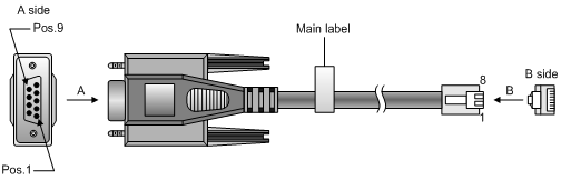
Console cable
A console cable is an 8-core shielded cable, with a crimped RJ-45 connector at one end for connecting to the console port of the switch, and a DB-9 female connector at the other end for connecting to the serial port on the console terminal.
Figure 24 Console cable
Connection procedure
To connect a terminal (for example, a PC) to the switch:
1. Plug the DB-9 female connector of the console cable to the serial port of the PC.
2. Connect the RJ-45 connector to the console port of the switch.
|
|
NOTE: · Identify the mark on the console port and make sure you are connecting to the correct port. · The serial ports on PCs do not support hot swapping. If the switch has been powered on, connect the console cable to the PC before connecting to the switch, and when you disconnect the cable, first disconnectfrom the switch. |
Setting terminal parameters
To configure and manage the switch, you must run a terminal emulator program on the console terminal.
The following are the required terminal settings:
· Bits per second—9,600
· Data bits—8
· Parity—None
· Stop bits—1
· Flow control—None
· Emulation—VT100
To set terminal parameters, for example, on a Windows XP HyperTerminal:
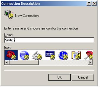
1. Select Start>All Programs>Accessories>Communications>HyperTerminal.
The Connection Descriptiondialog box appears.
2. Enter the name of the new connection in the Namefield and click OK.
Figure 25 Connection description
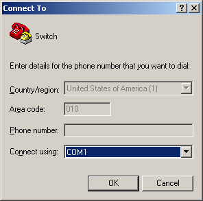
3. Select the serial port to be used from the Connect using list, and click OK.
Figure 26 Setting the serial port used by the HyperTerminal connection
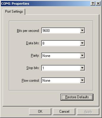
4. Set Bits per second to 9600, Data bits to 8, Parity to None, Stop bits to 1, and Flow control to None, and click OK.
Figure 27 Setting the serial port parameters
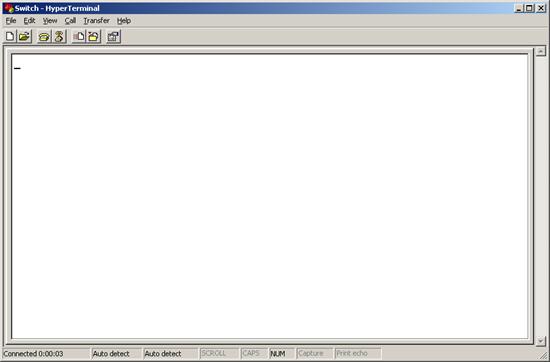
5. Select File>Properties in the HyperTerminal window.
Figure 28 HyperTerminal window
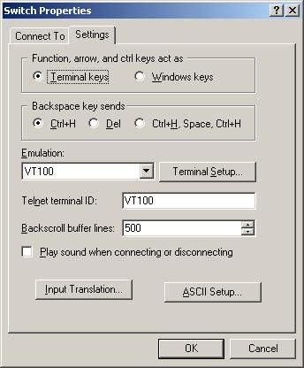
6. On the Settingstab, set the emulation to VT100 and click OK.
Figure 29 Setting terminal emulation in Switch Properties dialog box
Powering on the switch
Before powering on the switch, verify that the following conditions are met:
· The power cord iscorrectly connected.
· The input power voltage meets the requirement of the switch.
· The console cable is correctly connected.
· The configuration terminal (a PC, for example) has started, and its serial port settings are consistent with the console port settings on the switch.
Power on the switch. During the startup process, you can access Boot ROM menus to perform tasks such as software upgrade and file management. The Boot ROM interface and menu options differ with software versions. For more information about Boot ROM menu options, see the software-matching release notes for the device.
After the startup completes, you can access the CLI to configure the switch.
For more information about the configuration commands and CLI, see H3C S6300 Switch Series Configuration Guides and H3C S6300 Switch Series Command References.
Setting up an IRF fabric
You can use H3CIRF technology to connect and virtualize S6300 switches into a large virtual switch called an "IRF fabric" for flattened network topology, and high availability, scalability, and manageability.
IRF fabric setup flowchart
Figure 30 IRF fabric setup flowchart
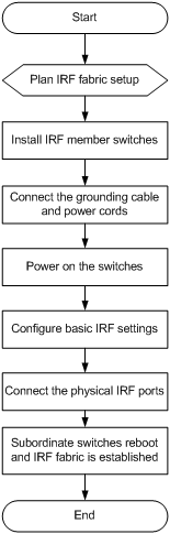
Toset up an IRF fabric:
|
Step |
Description |
|
1. Plan IRF fabric setup. |
Plan the installation site and IRF fabric setup parameters: · Planning IRF fabric size and the installation site · Identifying the master switch and planning IRF member IDs · Planning IRF topology and connections |
|
2. Install IRF member switches. |
|
|
3. Connect the groundingcable and power cords. |
See "Grounding the switch" and "Connecting the power cord." |
|
4. Power on the switches. |
N/A |
|
5. Configure basic IRF settings. |
See H3C S6300 Switch Series IRF Configuration Guide. |
|
6. Connect the physical IRF ports. |
See "Planning IRF topology and connections." All switches except the master switch automatically reboot, and the IRF fabric is established. |
Planning IRF fabric setup
This section describes issues that an IRF fabric setup plan must cover.
Planning IRF fabric size and the installation site
Choose switch models and identify the number of required IRF member switches, depending on the user density and upstream bandwidth requirements. The switching capacity of an IRF fabric equals the total switching capacities of all member switches.
Plan the installation site depending on your network solution as follows:
· Place all IRF member switches in one rackfor centralized high-density access.
· Distributethe IRF member switches in different racks to implement the top-of-rack (ToR) access solution for a data center.
As your business grows, you can plug H3C S6300 switches into the IRF fabric to increase the switching capacity without any topology change or replacement.
Identifying the master switch and planning IRF member IDs
Determine which switch you want to use as the master for managing all member switches in the IRF fabric. An IRF fabric has only one master switch. You configure and manage all member switches in the IRF fabric at the command line interface of the master switch.
|
|
NOTE: IRF member switches will automatically elect a master. You can affect the election result by assigning a high member priority to the intended master switch. For more information about master election, seeH3C S6300Switch Series IRF Configuration Guide. |
Prepare an IRF member ID assignment scheme. An IRF fabric uses member IDs to uniquely identify and manage its members, and you must assign each IRF member switch aunique member ID.
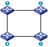
Planning IRF topology and connections
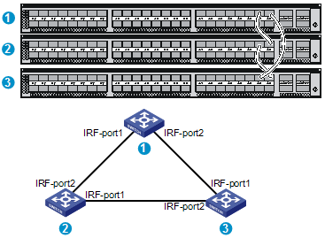
You can create an IRF fabric in daisy chain topology, or more reliably, ring topology. In ring topology, the failure of one IRF link does not cause the IRF fabric to split as in daisy chain topology. Rather, the IRF fabric changes to a daisy chain topology without interruptingnetwork services.
You connect the IRF member switches through IRF ports, the logical interfaces for the connectionsbetween IRF member switches. Each IRF member switch has two IRF ports: IRF-port 1andIRF-port 2. To use an IRF port, you must bind at least one physical port to it.
When connecting two neighboring IRF member switches, you must connect the physical ports of IRF-port 1on one switch to the physical ports of IRF-port 2 on the other switch.
The S6300-42QF and S6300-52QFswitchescan provide 10-GE and 40-GE IRF connections through SFP+ ports and QSFP+ ports, respectively.
The S6300-42QTswitch can provide 10-GE and 40-GE IRF connections through 1/10-GE Ethernet ports, SFP+ ports, or QSFP+ ports.
The S6300-48S switch can provide 10-GE IRF connections through SFP+ ports.
You can bind severalports of the same type to an IRF port for increased bandwidth and availability.
Figure 31 and Figure 32 show the topologies of an IRF fabric made up of three S6300 switches.The IRF port connections in the two figures are for illustration only, and more connection methods are available.
Figure 31 IRF fabric in daisy chain topology
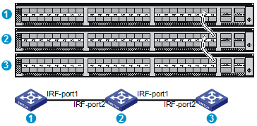
Figure 32 IRF fabric in ring topology
Identifying physical IRF ports on the member switches
Identify the ports to be used for IRF connections on the member switches according to your topology and connection scheme.
All ports on the front panel of the S6300 switch can be used for IRF connections.
Follow these guidelines when you identify 1/10-GE Ethernet ports and SFP+ports to be used for IRF connections:
· On anS6300-42QF, S6300-52QF, or S6300-48S switch, the SFP+ports are grouped by port number in ascending order, starting from one. Every four SFP+ports form one group.
· On an S6300-42QT switch, the 1/10-GE Ethernet ports and SFP+ ports are grouped by port number in ascending order, starting from 1 for 1/10-GE Ethernet ports and 33 for SFP+ ports, respectively. Every four ports form one group.
· Aport can be bound to an IRF port or operate as a service port. When aport is bound to an IRF port, other ports in the same port group cannot be used as service ports, and vice versa.
A common practice is to use one 1/10-GE Ethernet port/SFP+port group for IRF connections, and bind every two ports in the group to an IRF port for increased bandwidth and availability.
Planning the cabling scheme
Follow these guidelineswhen you use cables to connect switches:
· S6300-42QF/S6300-52QF switches—Use SFP+/QSFP+ cables or SFP+/QSFP+transceiver modules and fibers.
· S6300-42QT switches—Use category-6A or above twisted pair cables, SFP+/QSFP+ cables, or SFP+/QSFP+transceiver modules and fibers.
· S6300-48S switches—Use SFP+ cables or SFP+ transceiver modules and fibers.
If the IRF member switches are far away from one another, choose the SFP+/QSFP+transceiver modules with optical fibers. If the IRF member switches are all in one equipment room, choose category-6A or above twisted pair/SFP+/QSFP+ cables. For more information about available SFP+/QSFP+ cables and transceiver modules, see "SFP+ port" and "QSFP+ port."
The following subsections describe several H3C recommended IRF connection schemes, and all these schemes use a ring topology.
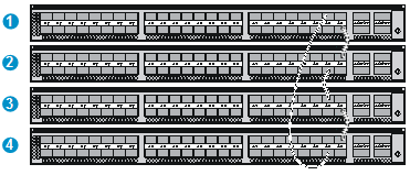
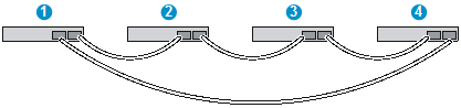
Connecting the IRF member switches inone rack
Use short-haul and long-haul SFP+ cables to connect the IRF member switches (fourswitches in this example) in a rack as shown inFigure 33. The switches in the ring topology (see Figure 34) are in the same order as connected in the rack.
Figure 33 Connecting the switches in one rack
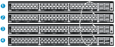
Connecting the IRF member switches in a ToR solution
You can install IRF member switches in different racks side by side to deploy a top of rack (ToR) solution.
Figure 35 shows an example for connecting fourtop of rack IRF member switches by using SFP+/QSFP+cables, and SFP+/QSFP+ transceiver modules, and optical fibers. The topology is the same as Figure 34.
Configuring basic IRF settings
After you install the IRF member switches, power on the switches, and log in to each IRF member switch (seeH3C S6300 Switch Series FundamentalsConfiguration Guide) to configure their member IDs, member priorities, and IRF port bindings.
Follow these guidelines when you configure the switches:
· Assign the master switch higher member priority than any other switch.
· Bind physical ports to IRF port 1 on one switch and to IRF port 2 on the other switch. You perform IRF port binding before or after connecting IRF physical ports depending on the software release.
· Tobind the ports on an interface card to an IRF port, you must install the interface card first. For how to install an interface card, seeH3C S6300 Switch Series Interface Cards User Guide.
· Execute the display irf configuration command to verify the basic IRF settings.
For more information about configuringbasic IRF settings, seeH3C S6300 Switch Series IRF Configuration Guide.
Connecting the physical IRF ports
Use category-6A or above twisted pair/SFP+/QSFP+ cables or SFP+/QSFP+transceiver modules and fibers to connect the IRF member switchesas planned.
|
|
NOTE: Wear an ESD wrist strap when you connect SFP+ cables or SFP+ transceiver modules and fibers. For more information, seeH3C SFP/SFP+/XFP/SFP28 Transceiver Modules and Cables Installation Guide and H3C QSFP+/QSFP28 Transceiver Modules and Cables Installation Guide. |
Accessing the IRF fabric to verify the configuration
To verify the basic functionality of the IRF fabricafter you finish configuring basic IRF settings and connecting IRF ports:
1. Log in to the IRF fabricthrough the console port of any member switch.
2. Create a Layer 3 interface, assign it an IP address, and make sure the IRF fabric and the remote network management station can reach each other.
3. Use Telnet, web,or SNMP to access the IRF fabric from the network management station. (See H3C S6300Switch Series FundamentalsConfiguration Guide.)
4. Verify that you can manage all member switches as if they were one node.
5. Display the running status of the IRF fabric by using the commands inTable 4.
Table 4 Displaying and maintaining IRF configuration and running status
|
Task |
Command |
|
Display information about the IRF fabric. |
display irf |
|
Display all members’IRF configurations. |
display irf configuration |
|
Display IRF fabric topology information. |
display irf topology |
|
|
NOTE: To avoid IP address collision and network problems, configure at least one multi-active detection (MAD) mechanism to detect the presence of multiple identical IRF fabrics and handle collisions. For more information about MAD detection, see H3C S6300Switch Series IRF Configuration Guide. |
Maintenance and troubleshooting
Power modulefailure
You can use the LEDs on the power module to identify a power module failure. For more information about the LEDs on a power module, seeH3C LSVM1AC300 & LSVM1DC300Power ModulesUser ManualandH3C LSVM1AC650 & LSVM1DC650Power ModulesUser Manual.
The LEDs on the power module are steady green (active) or flashing green (standby) while the power module system is correctly operating. If the LEDs behave in any other way, verify the following items:
· The switch power cord is correctly connected.
· The power source meets the requirement.
· The operating temperature of the switch is in the normal range and the power module has good ventilation.
If the problem persists, contact the H3C technical support for help.
To replace a power module, see "Installing/removinga power module."
Fantray failure
|
|
CAUTION: · Install two fan trays of the same model on the switch. · Do not operate the system with one failed fan tray for more than 24 hours. · Do not remove the failed fan tray until you are ready for replacing it. · Do not operate the system without any fan tray for more than 2 minutes. · Do not operate the system outside of the temperature range 0°C to 45°C (32°F to 113°F) degrees. |
When a fan tray has problems, the system status LED is steady red and the system outputs alarm messages.
To replace a failed fan tray, see "Installing/removing a fan tray."
Configuration terminal problems
If the configuration environment setup is correct, the configuration terminal displays booting information when the switch is powered on. If the setup is incorrect, the configuration terminal displays nothing or garbled text.
No terminal display
If the configuration terminal displays nothing when the switch is powered on, verify the following items:
· The power module is supplying power to the switch.
· The console cable is correctly connected.
· The console cable has no problem and the terminal settings are correct.
Garbled terminal display
If terminal display is garbled, verify that the following settings are configured for the terminal, for example, HyperTerminal:
· Baud rate—9,600
· Data bits—8
· Parity—none
· Stop bits—1
· Flow control—none
· Emulation—VT100
Appendix A Chassis views and technical specifications
Chassis views
S6300-42QF
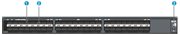
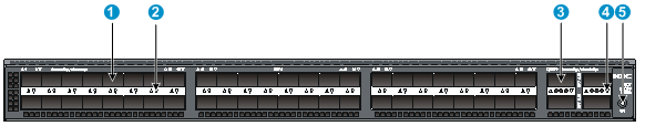
Figure 36 Front panel
|
(1) SFP+ port |
(2) SFP+ port LED |
|
(3) QSFP+ port |
(4) QSFP+ port LED |
|
(5) System status LED (SYS) |
|
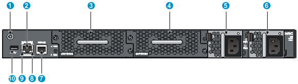
|
(1) Grounding screw (auxiliary grounding point 2) |
(2) Management Ethernet port |
|
(3) Fan tray slot 1 |
(4) Fan tray slot 2 |
|
(5) Power module slot 1 |
(6) Power module slot 2 |
|
(7) Console port |
(8) LINK LED for the management Ethernet port |
|
(9) ACT LED for the management Ethernet port |
(10) USB port |
The S6300-42QF switch comes with the power module slots empty and the filler modules for the slots as accessories. You can install one or two power modules for the switch as needed. In Figure 37, two LSVM1AC300power modules are installed. For more information about installing and removing a power module, see "Installing/removinga power module."
The S6300-42QF switch also comes with the fan tray slots empty. You must install two fan trays of the same model for the switch. In Figure 37, two LSWM1FANSC fan trays are installed. For more information about installing and removing a fan tray, see "Installing/removing a fan tray."
Figure 38 Left side panel
|
(1) Primary grounding point |
(2) Auxiliary grounding point 1 |
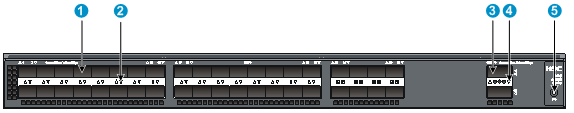
S6300-42QT
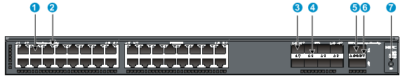
Figure 39 Front panel
|
(1) 1/10GBase-T autosensing Ethernet port |
(2) 1/10GBase-T autosensing Ethernet port LED |
|
(3) SFP+ port |
(4) SFP+ port LED |
|
(5) QSFP+ port |
(6) QSFP+ port LED |
|
(7) System status LED (SYS) |
|

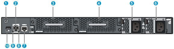
|
(1) Grounding screw (auxiliary grounding point 2) |
(2) Management Ethernet port |
|
(3) Fan tray slot 1 |
(4) Fan tray slot 2 |
|
(5) Power module slot 1 |
(6) Power module slot 2 |
|
(7) Console port |
(8) LINK LED for the management Ethernet port |
|
(9) ACT LED for the management Ethernet port |
(10) USB port |
The S6300-42QTswitch comes with the power module slots empty and the filler modules for the slots as accessories. You can install one or two power modules for the switch as needed. In Figure 40, two LSVM1AC650 power modules are installed. For more information about installing and removing a power module, see "Installing/removinga power module."
The S6300-42QTswitch also comes with the fan tray slots empty. You must install two fan trays of the same model for the switch. In Figure 40, two LSWM1HFANSC fan trays are installed. For more information about installing and removing a fan tray, see "Installing/removing a fan tray."
Figure 41 Left side panel
|
(1) Primary grounding point |
(2) Auxiliary grounding point 1 |
S6300-48S
Figure 42 Front panel
|
(1) SFP+ port |
(2) SFP+ port LED |
|
(3) System status LED (SYS) |
|
|
(1) Grounding screw (auxiliary grounding point 2) |
(2) Management Ethernet port |
|
(3) Fan tray slot 1 |
(4) Fan tray slot 2 |
|
(5) Power module slot 1 |
(6) Power module slot 2 |
|
(7) Console port |
(8) LINK LED for the management Ethernet port |
|
(9) ACT LED for the management Ethernet port |
(10) USB port |
The S6300-48Sswitch comes with the power module slots empty and the filler modules for the slots as accessories. You can install one or two power modules for the switch as needed. In Figure 43, two LSVM1AC300 power modules are installed. For more information about installing and removing a power module, see "Installing/removinga power module."
The S6300-48Sswitch also comes with the fan tray slots empty. You must install two fan trays of the same model for the switch. In Figure 43, two LSWM1FANSCfan trays are installed. For more information about installing and removing a fan tray, see "Installing/removing a fan tray."
Figure 44 Left side panel
|
(1) Primary grounding point |
(2) Auxiliary grounding point 1 |
S6300-52QF
Figure 45 Front panel
|
(1) SFP+ port |
(2) SFP+ port LED |
|
(3) QSFP+ port |
(4) QSFP+ port LED |
|
(5) System status LED (SYS) |
|

|
(1) Grounding screw (auxiliary grounding point 2) |
(2) Management Ethernet port |
|
(3) Fan tray slot 1 |
(4) Fan tray slot 2 |
|
(5) Power module slot 1 |
(6) Power module slot 2 |
|
(7) Console port |
(8) LINK LED for the management Ethernet port |
|
(9) ACT LED for the management Ethernet port |
(10) USB port |
The S6300-52QFswitch comes with the power module slots empty and the filler modules for the slots as accessories. You can install one or two power modules for the switch as needed. In Figure 46, two LSVM1AC300power modules are installed. For more information about installing and removing a power module, see "Installing/removinga power module."
The S6300-52QFswitch also comes with the fan tray slots empty. You must install two fan trays of the same model for the switch. In Figure 46, two LSWM1FANSC fan trays are installed. For more information about installing and removing a fan tray, see "Installing/removing a fan tray."
Figure 47 Left side panel
|
(1) Primary grounding point |
(2) Auxiliary grounding point 1 |
Technical specifications
|
Item |
S6300-42QF |
S6300-42QT |
S6300-48S |
S6300-52QF |
|
|
Dimensions (H × W × D) |
43.6 × 440 ×460 mm (1.72 × 17.32 ×18.11 in) |
43.6 × 440 × 660 mm (1.72 × 17.32 × 25.98 in) |
43.6 ×440×460 mm (1.72 × 17.32 ×18.11 in) |
43.6 × 440 ×460 mm (1.72 × 17.32 ×18.11 in) |
|
|
Weight |
≤10 kg (22.05 lb) |
≤13 kg (28.66 lb) |
≤ 10 kg (22.05 lb) |
≤10 kg (22.05 lb) |
|
|
Console ports |
1 |
||||
|
Management Ethernet ports |
1 |
||||
|
USB ports |
1 |
||||
|
SFP+ ports |
40 |
8 |
48 |
48 |
|
|
QSFP+ ports |
2 |
2 |
N/A |
4 |
|
|
1/10GBase-T autosensing Ethernet ports |
N/A |
32 |
N/A |
N/A |
|
|
Fan tray slots |
2, hot swappable, on the rear panel |
||||
|
Power module slots |
2, hot swappable, on the rear panel |
||||
|
AC-input voltage |
· Rated voltage: 100 VAC to 240 VAC @ 50 or 60Hz · Max voltage: 90 VAC to 264VAC @ 47 to 63 Hz |
||||
|
DC-input voltage |
Rated voltage:–48 VDC to –60 VDC |
Rated voltage:–40 VDC to –60 VDC |
Rated voltage:–48 VDC to –60 VDC |
Rated voltage:–48 VDC to –60 VDC |
|
|
Minimum power consumption |
· Single AC input: 83 W · Dual AC inputs: 90W · Single DC input: 80W · Dual DC inputs: 88W |
· Single AC input: 135W · Dual AC inputs: 150W · Single DC input: 135W · Dual DC inputs: 150 W |
· Single AC input: 87W · Dual AC inputs: 93W · Single DC input: 82W · Dual DC inputs: 88W |
· Single AC input: 97W · Dual AC inputs: 106W · Single DC input: 96W · Dual DC inputs: 105W |
|
|
Maximum power consumption |
· Single AC input: 153W · Dual AC inputs: 162W · Single DC input: 149W · Dual DC inputs: 157W |
· Single AC input: 343W · Dual AC inputs: 350 W · Single DC input: 340 W · Dual DC inputs: 344 W |
· Single AC input: 160W · Dual AC inputs: 165 W · Single DC input: 151 W · Dual DC inputs: 157 W |
· Single AC input: 191W · Dual AC inputs: 196W · Single DC input: 187W · Dual DC inputs: 190W |
|
|
Chassis leakage current compliance |
UL60950-1, EN60950-1, IEC60950-1, and GB4943 |
||||
|
Melting current of power module fuse |
AC power module |
6.3 A @ 250 VAC |
10 A @ 250 VAC |
6.3 A @ 250 VAC |
6.3 A @ 250 VAC |
|
DC power module |
25 A @ 250 VDC |
30 A @ 250 VDC |
25 A @ 250 VDC |
25 A @ 250 VDC |
|
|
Operating temperature |
0°C to 45°C (32°F to 113°F) |
||||
|
Operating humidity |
10% to 90%, noncondensing |
||||
|
Fire resistance compliance |
UL60950-1, EN60950-1, IEC60950-1, and GB4943 |
||||
Appendix B FRUs and compatibility matrixes
This appendix describes the field replaceable units (FRUs) available for the S6300switchesand their compatibility.
All the FRUs in this appendix are hot swappable.
Power modules
|
Power module |
Specifications |
Switch model |
Remarks |
|
LSVM1AC300 |
· Rated input voltage: · Max input voltage: · Max output power: |
· S6300-42QF · S6300-48S · S6300-52QF |
For more information about the power modules, see H3C LSVM1AC300& LSVM1DC300 Power ModulesUser Manual. |
|
LSVM1DC300 |
· Rated input voltage: · Max input voltage: · Max output power: |
||
|
LSVM1AC650 |
· Rated input voltage: · Max input voltage: · Max output power: |
S6300-42QT |
For more information about the power modules, see H3C LSVM1AC650 & LSVM1DC650Power ModulesUser Manual. |
|
LSVM1DC650 |
· Rated input voltage: · Max input voltage: · Max output power: |
|
|
NOTE: When a switch has two power modules for redundancy, you can replace a power module without powering off the switch. Make sure the power module to be replaced is powered off before you replace it. |
Fan trays
|
Item |
Specifications |
|
LSWM1FANSC (for the S6300-42QF/S6300-48S/S6300-52QF switch) |
|
|
Fans |
Two 40 × 40 × 28 mm (1.57 × 1.57 × 1.1 in) fans |
|
Fan speed |
18500 R.P.M |
|
Max airflow |
45 CFM |
|
Airflow direction |
Back to front (Fans blow air from the power module side to the network port side.) |
|
Input voltage |
12 V |
|
Maximumpower consumption |
19.5 W |
|
Documentation reference |
H3CLSWM1FANSC & LSWM1FANSCB Installation Manual |
|
LSWM1FANSCB (for the S6300-42QF/S6300-48S/S6300-52QF switch) |
|
|
Fans |
Two 40 × 40 × 28 mm (1.57 × 1.57 × 1.1 in) fans |
|
Fan speed |
18500 R.P.M |
|
Max airflow |
45 CFM |
|
Airflow direction |
Front to back (Fans draw air from the network port side to the power module side.) |
|
Input voltage |
12 V |
|
Maximumpower consumption |
19.5 W |
|
Documentation reference |
H3CLSWM1FANSC & LSWM1FANSCB Installation Manual |
|
LSWM1HFANSC (for the S6300-42QT switch) |
|
|
Fans |
Two 40 × 40 × 56 mm (1.57 × 1.57 × 2.2 in) fans |
|
Fan speed |
21000 R.P.M |
|
Max airflow |
70CFM |
|
Airflow direction |
Back to front (Fans draw air from the power module side to the network port side.) |
|
Input voltage |
12 V |
|
Maximum power consumption |
60W |
|
Documentation reference |
H3C LSWM1HFANSC&LSWM1HFANSCB Installation Manual |
|
LSWM1HFANSCB (for the S6300-42QT switch) |
|
|
Fans |
Two 40 × 40 × 56 mm (1.57 × 1.57 × 2.2 in) fans |
|
Fan speed |
21000 R.P.M |
|
Max airflow |
70CFM |
|
Airflow direction |
Front to back (Fans draw air from the network port side to the power module side.) |
|
Input voltage |
12 V |
|
Maximum power consumption |
60W |
|
Documentation reference |
H3C LSWM1HFANSC&LSWM1HFANSCB Installation Manual |
|
|
CAUTION: The switch comes with the fan tray slots empty. You must install two fan trays for the switch for adequate heat dissipation, and their models must be the same. You must not power on the switch when no fan tray is installed. |
Appendix C Ports and LEDs
Ports
Console port
The switch has one console port.
Table 5 Console port specifications
|
Item |
Specification |
|
Connector type |
RJ-45 |
|
Compliant standard |
EIA/TIA-232 |
|
Transmission baud rate |
9600bps(default) to 115200bps |
|
Services |
· Provides connection to an ASCII terminal. · Provides connection to the serial port of a local or remote (through a pair of modems) PC running terminal emulation program. |
Management Ethernet port
Theswitch has one management Ethernet port. You can connect this port to a PC or management station for loading and debugging software or remote management.
Table 6 Management Ethernet port specifications
|
Item |
Specification |
|
Connector type |
RJ-45 |
|
Connector quantity |
1 |
|
Port transmission rate |
10/100/1000 Mbps, half/full duplex |
|
Transmission medium and max transmission distance |
100 m (328.08 ft) over category-5 twisted pair cable |
|
Functions and services |
Switch software and Boot ROM upgrade, network management |
USB port
The switch has oneOHC-compliant USB2.0 port that can upload and download data at a rate up to 12 Mbps. You can use this USB port to access the file system on the Flash of the switch, for example, to upload or download application and configuration files.
|
|
NOTE: USB devices from different vendors vary in compatibility and driver. H3C does not guarantee correct operation of USB devices from other vendors on the switch. If a USB device does not operate correctly on the switch, replace it with one from another vendor. |
SFP+ port
The switch provides SFP+ ports. You can plug the SFP transceiver modules in Table 7, the SFP+ transceiver modules in Table 8, andthe SFP+ DAC cables in Table 9or SFP+ AOC cables in Table 10into the SFP+ports as needed. You can use the SFP+ ports as IRF physical ports to connect the switches in an IRF deployment.
Table 7 1000 Mbps SFP transceiver modules available for the SFP+ ports
|
Transceiver module |
Central wavelength (nm) |
Connector |
Cable/fiber diameter |
Multimode fiber modal bandwidth |
Max transmission distance |
|
SFP-GE-T |
N/A |
RJ-45 |
Category-5 twisted pair |
N/A |
100 m (328.08 ft) |
|
SFP-GE-SX-MM850-A |
850 |
LC |
Multi-mode, 50/125 µm |
500 |
550m(1804.46 ft) |
|
400 |
500 m (1640.42 ft) |
||||
|
Multi-mode, 62.5/125 µm |
200 |
275m(902.23 ft) |
|||
|
160 |
220 m (721.78 ft) |
||||
|
SFP-GE-LX-SM1310-A |
1310 |
LC |
Single-mode, 9/125 µm |
N/A |
10 km(6.21 miles) |
|
Multi-mode, 50/125 µm |
500 or 400 |
550 m (1804.46 ft) |
|||
|
Multi-mode, 62.5/125 µm |
500 |
550 m (1804.46 ft) |
|||
|
SFP-GE-LH40-SM1310 |
1310 |
LC |
Single-mode, 9/125 µm |
N/A |
40 km(24.86 miles) |
|
SFP-GE-LH40-SM1550 |
1550 |
LC |
Single-mode, 9/125 µm |
N/A |
40 km(24.86 miles) |
|
SFP-GE-LH80-SM1550 |
1550 |
LC |
Single-mode, 9/125 µm |
N/A |
80 km (49.71 miles) |
Table 8 10 Gbps SFP+ transceiver modules available for the SFP+ ports
|
Transceiver module |
Central wavelength (nm) |
Connector |
Fiber diameter |
Multimode
fiber modal bandwidth |
Max transmission distance |
|
SFP-XG-SX-MM850-A |
850nm |
LC |
Multi-mode, 50/125 µm |
2000 |
300 m (984.3 ft) |
|
500 |
82 m (269.03 ft) |
||||
|
400 |
66 m (216.54 ft) |
||||
|
Multi-mode, 62.5/125 µm |
200 |
33 m (108.27 ft) |
|||
|
160 |
26 m (85.3 ft.) |
||||
|
SFP-XG-SX-MM850-E |
850nm |
LC |
Multi-mode, 50/125 µm |
2000 |
300 m (984.3 ft) |
|
500 |
82 m (269.03 ft) |
||||
|
400 |
66 m (216.54 ft) |
||||
|
200 |
33 m (108.27 ft) |
||||
|
160 |
26 m (85.3 ft.) |
||||
|
SFP-XG-LX-SM1310 |
1310 nm |
LC |
Single-mode, 9/125 µm |
N/A |
10 km (6.21 miles) |
|
SFP-XG-LX-SM1310-E |
1310 nm |
LC |
Single-mode, 9/125 µm |
N/A |
10 km (6.21 miles) |
Table 9 SFP+ DAC cables available for the SFP+ ports
|
Cable model |
Cable description |
Cable length |
|
LSWM1STK |
10G SFP+ SFP+0.65m Direct Attach Copper Cable |
0.65 m (2.13 ft) |
|
LSWM2STK |
10G SFP+ SFP+ 1.2m Direct Attach Copper Cable |
1.2 m (3.94 ft) |
|
LSWM3STK |
10G SFP+ SFP+ 3m Direct Attach Copper Cable |
3 m (9.84 ft) |
|
LSTM1STK |
10G SFP+ SFP+5m Direct Attach Copper Cable |
5 m (16.40 ft) |
Table 10 SFP+ AOC cables available for the SFP+ ports
|
Cable model |
Cable length |
Transmission speed |
|
SFP-XG-D-AOC-7M |
7 m (22.97 ft) |
10.31 Gbps |
|
SFP-XG-D-AOC-10M |
10 m (32.81 ft) |
|
|
SFP-XG-D-AOC-20M |
20 m (65.62 ft) |
|
|
NOTE: · To guarantee the functionality of the SFP+ ports, use only H3C SFP or SFP+ transceiver modules, DAC cables, and AOC cables. · The SFP and SFP+ transceiver modules, DAC and AOC cables available for this switch series are subject to change over time. For the most up-to-date list of SFP transceiver modules, consult your H3C sales representative or technical support engineer. |
For the transceiver module specifications, see H3C Transceiver Modules User Guide.
The SFP+ DAC and AOC cables available for the H3C S6300switcheslisted in Table 9 and Table 10. Figure 48 shows an example of an SFP+ DAC cable.
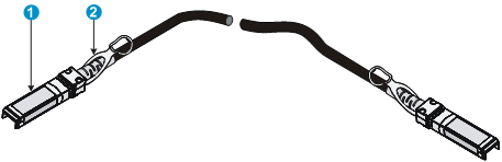
|
(1) Connector |
(2) Pull latch |
QSFP+ port
The S6300-42QF, S6300-42QT, and S6300-52QFswitches provide QSFP+ ports. You can plug the QSFP+ transceiver modules in Table 11 andthe QSFP+ DAC cables in Table 12and QSFP+ AOC cables in Table 13into the QSFP+ports as needed.
|
|
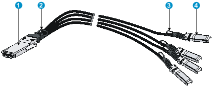
NOTE: The QSFP-40G-SR4-MM850 transceiver module and QSFP-40G-CSR4-MM850transceiver module can be used to connect one 40G QSFP+ port to four 10G SFP+ ports. The QSFP+ transceiver modules and SFP+ transceiver modules to be connected must be the same in specifications, including central wavelength and fiber diameter. |
Table 11 QSFP+ transceiver modules available for the switch
|
Transceiver module model |
Central wavelength (nm) |
Connector |
Fiber |
Multimode fiber modal bandwidth |
Max transmission distance |
|
QSFP-40G-SR4-MM850 |
850 |
MPO |
Multi-mode, 50/125µm |
2000 |
100 m (328.08 ft) |
|
4700 |
150 m (492.12 ft) |
||||
|
QSFP-40G-CSR4-MM850 |
850 |
MPO |
Multi-mode, 50/125µm |
2000 |
300 m (984.25 ft) |
|
4700 |
400 m (1312.33 ft) |
||||
|
QSFP-40G-LR4-WDM1300 |
Four lanes: · 1271 · 1291 · 1311 · 1331 |
LC |
Single-mode, 9/125µm |
N/A |
10 km (6.21 miles) |
|
QSFP-40G-LR4L-WDM1300 |
Four lanes: · 1271 · 1291 · 1311 · 1331 |
LC |
Single-mode, 9/125µm |
N/A |
2 km (1.24 miles) |
Table 12 QSFP+ cables available for the switch
|
Cable model |
Cable description |
Cable length |
|
LSWM1QSTK0 |
40G QSFP+ QSFP+ 1m Direct Attach Copper Cable |
1 m (3.28 ft) |
|
LSWM1QSTK1 |
40G QSFP+ QSFP+ 3m Direct Attach Copper Cable |
3 m (9.84 ft) |
|
LSWM1QSTK2 |
40G QSFP+ QSFP+ 5m Direct Attach Copper Cable |
5 m (16.40 ft) |
|
LSWM1QSTK3 |
40G QSFP+ to 4x10G SFP+ 1m Direct Attach Copper Splitter Cable |
1 m (3.28 ft) |
|
LSWM1QSTK4 |
40G QSFP+ to 4x10G SFP+ 3m Direct Attach Copper Splitter Cable |
3 m (9.84 ft) |
|
LSWM1QSTK5 |
40G QSFP+ to 4x10G SFP+ 5m Direct Attach Copper Splitter Cable |
5 m (16.40 ft) |
Table 13 QSFP+ AOC cables available for the QSFP+ ports
|
Cable model |
Cable length |
Transmission speed |
|
QSFP-40G-D-AOC-7M |
7 m (22.97 ft) |
40 Gbps |
|
QSFP-40G-D-AOC-10M |
10 m (32.81 ft) |
|
|
QSFP-40G-D-AOC-20M |
20 m (65.62 ft) |
The QSFP+ DAC and AOC cables available for the H3C S6300switcheslisted in Table 12 and Table 13. Figure 49 shows an example of a QSFP+ DAC cable.
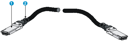
|
(1) Connector |
(2) Pull latch |
Figure 50 40G QSFP+ to 4x10G SFP+ cable
|
(1) QSFP+ module |
(2) QSFP+ side pull latch |
|
(3) SFP+ side pull latch |
(4) SFP+ module |
|
|
NOTE: · To guarantee the functionality of the QSFP+ ports, use only H3C QSFP+ transceiver modules, DAC cables, and AOC cables on the S6300-42QF, S6300-42QT, and S6300-52QF switches. · The QSFP+ transceiver modules and DAC and AOC cables available for this switch series are subject to change over time. For the most up-to-date list of QSFP+ transceiver modulesand cables, consult your H3C sales representative or technical support engineer. |
For QSFP+ transceiver module and cable specifications, see H3C Transceiver Modules User Guide.
1/10GBase-T autosensing Ethernet port
The S6300-42QT switch has 1/10GBase-T autosensing Ethernet ports.
Table 14 1/10GBase-T autosensing Ethernet port specifications
|
Item |
Specification |
|
Connector type |
RJ-45 |
|
Port transmission rate |
1/10 Gbps, full duplex, MDI/MDI-X autosensing |
|
Transmission medium and max transmission distance |
· 55 m (180.45 ft) over category-6 unshielded twisted pair cable · 100 m (328.08 ft) over category-6 shielded twisted pair cable · 100 m (328.08 ft) over category-6A or above twisted pair cable |
|
Compatible standards |
· IEEE 802.3ab · IEEE 802.3an |
To avoid interference betweencables as a best practice, layer cables as follows:
· Use category-6A or abovecables andconnectors.
· Do not bundle cables in their first 20 m (65.62 ft).
· Separate power cables and twisted pair cables at and around the distribution frame.
· For ports adjacent to one another on the device, the peer ports on thedistribution frame is preferably not adjacent, for example:
¡ If the device connects to onedistribution frame, connect port 1 on the device to port 1 on the distribution frame, port 2 on the device to port 3 on the distribution frame, and port 3 on the device to port 5 on the distribution frame.
¡ If the device connects to two distribution frames, connect port 1 on the device to port 1 on distribution frame 1, port 2 on the device to port 1 on distribution frame 2, and port 3 on the device to port 2 on distribution frame 1.
LEDs
System status LED
The system status LED shows the operating status of the switch.
Table 15 System status LED description
|
LED mark |
Status |
Description |
|
SYS |
Steady green |
The switch is operating correctly. |
|
Flashing green |
The switch is performing power-on self test (POST). |
|
|
Steady red |
The systemhas failed to pass POST or has problems such as fan failure. |
|
|
Flashingred |
Some ports have failed to pass POST. |
|
|
Off |
The switch is powered offor has failed to start up. |
SFP+ port LED
Each SFP+ port has a status LED to show port operating status and activities.
Table 16 SFP+ port LED description
|
LED status |
Description |
|
Steady green |
A transceiver module or cable has been correctly installed. The port has a link and is operating at 10 Gbps. |
|
Flashing green |
The port is sending or receiving data at 10 Gbps. |
|
Steady yellow |
A transceiver module or cable has been correctly installed. The port has a link and is operating at 1 Gbps. |
|
Flashing yellow |
The port is sending or receiving data at 1 Gbps. |
|
Off |
No transceiver module or cable has been installed or no link is present on the port. |
QSFP+ port LED
Each QSFP+ port has a status LED to show port operating status and activities.
Table 17 QSFP+ port LED description
|
LED status |
Description |
|
Steady green |
A transceiver module or cable has been correctly installed. The port has a link and is operating at 40 Gbps. |
|
Flashing green |
The port is sending or receiving data at 40 Gbps. |
|
Steady yellow |
A transceiver module or cable has been correctly installed. The port has a link and is operating at 10 Gbps. |
|
Flashing yellow |
The port is sending or receiving data at 10 Gbps. |
|
Off |
No transceiver module or cable has been installed or no link is present on the port. |
1/10GBase-T autosensing Ethernet port LEDs
Table 18 1/10GBase-T autosensing Ethernet port LED description
|
Status |
Description |
|
Steady green |
The port has a link and is operating at 10 Gbps. |
|
Flashing green |
The port is sending or receiving data at 10 Gbps. |
|
Steady yellow |
The port has a link and is operating at 1 Gbps. |
|
Flashing yellow |
The port is sending or receivingdata at 1 Gbps. |
|
Off |
No link is present on the port. |
Management Ethernet port LEDs
A management Ethernet port has one LINK LED and one ACT LED to show its link and data transmission status.
Table 19 Management Ethernet port LED description
|
LED mark |
Status |
Description |
|
LINK |
Off |
The management Ethernet port is not connected. |
|
Steady green |
The management Ethernet port is operating at 10/100/1000Mbps. |
|
|
ACT |
Off |
The management Ethernet port is not receiving or sending data. |
|
Flashing yellow |
The management Ethernet port is sending or receivingdata. |
Appendix D Cooling system
The cooling system of the switchuses front-back ventilation. To guarantee that this cooling system can effectively work, you must consider thesite ventilation design when you plan the installation site for the switches.
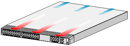
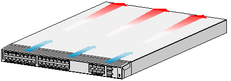
Table 20 Switch fan tray ventilation description
|
Switch model |
Fan tray |
Air flow direction |
|
· S6300-42QF · S6300-48S · S6300-52QF |
LSWM1FANSC |
Air flows in through the power module side and exhausts at the network port side |
|
LSWM1FANSCB |
Air flows in through the network port side and exhausts at the powermodule side |
|
|
S6300-42QT |
LSWM1HFANSC |
Air flows in through the power module side and exhausts at the network port side |
|
LSWM1HFANSCB |
Air flows in through the network port side and exhausts at the powermodule side |
|
|
NOTE: To ensure correct ventilation, fan trays on the switch must have the same air flow direction. |
A
Accessing the IRF fabric to verify the configuration,30
C
Chassis views,33
Configuration terminal problems,31
Configuring basic IRF settings,29
Connecting the console cable,20
Connecting the physical IRF ports,29
Connecting the power cord,17
E
Examining the installation site,1
F
Fan tray failure,31
Fan trays,40
G
Grounding the switch,11
I
Installation tools,3
Installing the switch in a 19-inch rack,4
Installing/removing a fan tray,13
Installing/removing a power module,15
IRF fabric setup flowchart,25
L
LEDs,47
P
Planning IRF fabric setup,26
Ports,42
Power module failure,31
Power modules,39
Powering on the switch,24
S
Safety recommendations,1
Setting terminal parameters,21
Setting up the configuration environment,20
T
Technical specifications,37
V
Verifying the installation,18
