- Table of Contents
-
- H3C Fixed Port Campus Switches Configuration Examples-B70D022-6W100
- 01-Login Management Configuration Examples
- 02-RBAC Configuration Examples
- 03-Software Upgrade Examples
- 04-ISSU Configuration Examples
- 05-Software Patching Examples
- 06-Ethernet Link Aggregation Configuration Examples
- 07-Port Isolation Configuration Examples
- 08-Spanning Tree Configuration Examples
- 09-VLAN Configuration Examples
- 10-VLAN Tagging Configuration Examples
- 11-DHCP Snooping Configuration Examples
- 12-Cross-Subnet Dynamic IP Address Allocation Configuration Examples
- 13-IPv6 over IPv4 Manual Tunneling with OSPFv3 Configuration Examples
- 14-ISATAP Tunnel and 6to4 Tunnel Configuration Examples
- 15-GRE Tunnel Configuration Examples
- 16-GRE with OSPF Configuration Examples
- 17-OSPF Configuration Examples
- 18-IS-IS Configuration Examples
- 19-BGP Configuration Examples
- 20-Policy-Based Routing Configuration Examples
- 21-OSPFv3 Configuration Examples
- 22-IPv6 IS-IS Configuration Examples
- 23-Routing Policy Configuration Examples
- 24-IGMP Snooping Configuration Examples
- 25-IGMP Configuration Examples
- 26-BIDIR-PIM Configuration Examples
- 27-Multicast VPN Configuration Examples
- 28-MLD Snooping Configuration Examples
- 29-IPv6 Multicast VLAN Configuration Examples
- 30-Basic MPLS Configuration Examples
- 31-MPLS L3VPN Configuration Examples
- 32-ACL Configuration Examples
- 33-Control Plane-Based QoS Policy Configuration Examples
- 34-Traffic Policing Configuration Examples
- 35-GTS and Rate Limiting Configuration Examples
- 36-Priority Mapping and Queue Scheduling Configuration Examples
- 37-Traffic Filtering Configuration Examples
- 38-AAA Configuration Examples
- 39-Port Security Configuration Examples
- 40-Portal Configuration Examples
- 41-SSH Configuration Examples
- 42-IP Source Guard Configuration Examples
- 43-Ethernet OAM Configuration Examples
- 44-CFD Configuration Examples
- 45-DLDP Configuration Examples
- 46-VRRP Configuration Examples
- 47-BFD Configuration Examples
- 48-NTP Configuration Examples
- 49-SNMP Configuration Examples
- 50-NQA Configuration Examples
- 51-Mirroring Configuration Examples
- 52-sFlow Configuration Examples
- 53-OpenFlow Configuration Examples
- 54-MAC Address Table Configuration Examples
- 55-Static Multicast MAC Address Entry Configuration Examples
- 56-IP Unnumbered Configuration Examples
- 57-MVRP Configuration Examples
- 58-MCE Configuration Examples
- 59-Congestion Avoidance and Queue Scheduling Configuration Examples
- 60-Attack Protection Configuration Examples
- 61-Smart Link Configuration Examples
- 62-RRPP Configuration Examples
- 63-BGP Route Selection Configuration Examples
- 64-IS-IS Route Summarization Configuration Examples
- 65-IRF Configuration Examples
- 66-MPLS TE Configuration Examples
- 67-VXLAN Configuration Examples
- 68-VCF Fabric Configuration Examples
- Related Documents
-
| Title | Size | Download |
|---|---|---|
| 55-Static Multicast MAC Address Entry Configuration Examples | 67.23 KB |
Introduction
This document provides configuration examples of static multicast MAC address entries.
Prerequisites
The configuration examples in this document were created and verified in a lab environment, and all the devices were started with the factory default configuration. When you are working on a live network, make sure you understand the potential impact of every command on your network.
This document assumes that you have basic knowledge of multicast MAC addresses.
Example: Configuring static multicast MAC address entries
Network configuration
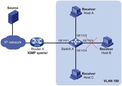
As shown in Figure 1, Router A runs IGMP and acts as the IGMP querier. Switch A does not run a Layer 2 multicast protocol.
Configure a static multicast MAC address entry on Switch A so that only Host A and Host C can receive multicast data for multicast group 224.1.1.1.
Analysis
Multicast MAC address entries guide Layer 2 multicast forwarding. They can be dynamically created through Layer 2 multicast protocols or manually configured by binding multicast MAC addresses and ports.
In this example, Switch A does not run a Layer 2 multicast protocol. To control destination ports of Layer 2 multicast data, configure a static multicast MAC address entry on Switch A.
Applicable hardware and software versions
The following matrix shows the hardware and software versions to which this configuration example is applicable:
|
Hardware |
Software version |
|
S6520XE-HI switch series |
Supported in Release 11xx |
|
S5560X-EI switch series |
Supported in Release 111x |
|
S5500V2-EI switch series |
Supported in Release 111x |
|
MS4520V2-30F switch |
Supported in Release 111x |
|
S5560S-EI switch series S5560S-SI switch series |
Supported in Release 612x |
|
S5130S-HI switch series S5130S-EI switch series S5130S-SI switch series S5130S-LI switch series |
Supported in Release 612x |
|
S5120V2-SI switch series S5120V2-LI switch series |
Supported in Release 612x |
|
S3100V3-EI switch series S3100V3-SI switch series |
Supported in Release 612x |
|
S5110V2 switch series |
Supported in Release 612x |
|
S5110V2-SI switch series |
Supported in Release 612x |
|
S5000V3-EI switch series |
Supported in Release 612x |
|
S5000E-X switch series |
Supported in Release 612x |
|
WAS6000 switch series |
Supported in Release 612x |
|
E128C switch E152C switch E500C switch series E500D switch series |
Supported in Release 612x |
|
MS4520V2 switch series (except the MS4520V2-30F switch) |
Supported in Release 612x |
|
MS4320V2 switch series MS4300V2 switch series MS4320 switch series MS4200 switch series |
Supported in Release 612x |
|
WS5850-WiNet switch series |
Supported in Release 612x |
|
WS5820-WiNet switch series WS5810-WiNet switch series |
Supported in Release 612x |
Restrictions and guidelines
You must specify an unused multicast MAC address in a manually configured multicast MAC address entry.
Procedures
# On Switch A, create VLAN 100.
<SwitchA> system-view
[SwitchA] vlan 100
[SwitchA-vlan100] quit
# Configure GigabitEthernet 1/0/1 through GigabitEthernet 1/0/4 to operate in Layer 2 mode, and assign the ports to VLAN 100.
[SwitchA] interface range gigabitethernet 1/0/1 to gigabitethernet 1/0/4
[SwitchA-if-range] port access vlan 100
[SwitchA-if-range] quit
# Translate the multicast IP address 224.1.1.1 to a multicast MAC address (0100-5e01-0101). (Details not shown.)
# Create a static entry for the multicast MAC address 0100-5e01-0101 with GigabitEthernet 1/0/2 and GigabitEthernet 1/0/4 in VLAN 100 as outgoing ports.
[SwitchA] mac-address multicast 0100-5e01-0101 interface gigabitethernet 1/0/2 gigabitethernet 1/0/4 vlan 100
Verifying the configuration
# Display static multicast MAC address entries for VLAN 100 on Switch A.
[SwitchA] display mac-address multicast vlan 100
MAC Address VLAN ID State Port/NickName Aging
0100-5e01-0101 100 Multicast GE1/0/2 N
GE1/0/4
The output shows that GigabitEthernet 1/0/2 and GigabitEthernet 1/0/4 have become outgoing ports of the multicast MAC group 0100-5e01-0101.
Configuration files
|
|
IMPORTANT: The port link-mode bridge command is available only on the following switches: · S6520XE-HI switch series. · S5560X-EI switch series. · S5500V2-EI switch series. · MS4520V2-30F switch. |
#
vlan 100
#
interface GigabitEthernet1/0/1
port link-mode bridge
port access vlan 100
#
interface GigabitEthernet1/0/2
port link-mode bridge
port access vlan 100
#
interface GigabitEthernet1/0/3
port link-mode bridge
port access vlan 100
#
interface GigabitEthernet1/0/4
port link-mode bridge
port access vlan 100
#
mac-address multicast 0100-5e01-0101 interface GigabitEthernet1/0/2 GigabitEthernet1/0/4 vlan 100
#
