- Released At: 14-01-2019
- Page Views:
- Downloads:
- Table of Contents
- Related Documents
-
H3C LSWM116Q interface
card
user manual-6PW104
▌Introduction
Overview
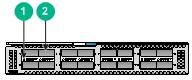
The LSWM116Q interface card provides 16 QSFP+ ports.
Figure 1 Front panel
|
(1) QSFP+ port LED |
(2) QSFP+ port |
QSFP+ ports
Table 1 and Table 2 describe QSFP+ transceiver modules and Table 3 describes QSFP+ cables available for the QSFP+ ports on the card.
Table 1 QSFP+ transceiver modules available for the QSFP+ ports (1)
|
QSFP+ transceiver module |
Central wavelength (nm) |
Connector |
|
QSFP-40G-SR4-MM850 |
850 |
MPO (PC polished, 12-fiber) |
|
QSFP-40G-CSR4-MM850 |
850 |
MPO (PC polished, 12-fiber) |
|
QSFP-40G-LR4-PSM1310 |
1310 |
MPO (APC polished, 12-fiber) |
|
QSFP-40G-BIDI-SR-MM850 |
850 |
LC |
|
QSFP-40G-LR4-WDM1300 |
Four lanes: · 1271 · 1291 · 1311 · 1331 |
LC |
|
QSFP-40G-LR4L-WDM1300 |
Four lanes: · 1271 · 1291 · 1311 · 1331 |
LC |
Table 2 QSFP+ transceiver modules available for the QSFP+ ports (2)
|
QSFP+ transceiver module |
Cable/fiber diameter (μm) |
Modal bandwidth (MHz × km) |
Max transmission distance |
|
QSFP-40G-SR4-MM850 |
Multi-mode, 50/125 |
2000 |
100 m (328.08 ft) |
|
4700 |
150 m (492.12 ft) |
||
|
QSFP-40G-CSR4-MM850 |
Multi-mode, 50/125 |
2000 |
300 m (984.25 ft) |
|
4700 |
400 m (1312.33 ft) |
||
|
QSFP-40G-LR4-PSM1310 |
Single-mode, 9/125 |
N/A |
10 km (6.21 miles) |
|
QSFP-40G-BIDI-SR-MM850 |
Multi-mode, 50/125 |
2000 |
100 m (328.08 ft) |
|
4700 |
150 m (492.12 ft) |
||
|
QSFP-40G-LR4-WDM1300 |
Single-mode, 9/125 |
N/A |
10 km (6.21 miles) |
|
QSFP-40G-LR4L-WDM1300 |
Single-mode, 9/125 |
N/A |
2 km (1.24 miles) |
Table 3 QSFP+ cables available for the QSFP+ ports
|
QSFP+ cable |
Cable length |
Data rate |
|
QSFP+ copper cable |
||
|
LSWM1QSTK0 |
1 m (3.28 ft) |
40 Gbps |
|
LSWM1QSTK1 |
3 m (9.84 ft) |
|
|
LSWM1QSTK2 |
5 m (16.40 ft) |
|
|
QSFP+ fiber cable |
||
|
QSFP-40G-D-AOC-7M |
7 m (22.97 ft) |
40 Gbps |
|
QSFP-40G-D-AOC-10M |
10 m (32.81 ft) |
|
|
QSFP-40G-D-AOC-20M |
20 m (65.62 ft) |
|
|
|
NOTE: · As a best practice, use H3C transceiver modules and cables for the interface card. · The transceiver module and cable types supported by an interface card vary by device model. For more information, see the installation guide or contact H3C Support or marketing staff. |
For more information about H3C transceiver modules and cables, see H3C Transceiver Modules User Guide at www.h3c.com.
LEDs
Table 4 describes QSFP+ port LEDs on the front panel.
Table 4 QSFP+ port LED description
|
LED status |
Description |
|
Steady green |
A transceiver module is installed in the port. The port is operating at 40 Gbps, and a link is present on the port. |
|
Flashing green |
The port is sending or receiving data at 40 Gbps. |
|
Off |
No transceiver module is installed in the port, or no link is present on the port. |
▌Installing and removing the card
|
|
CAUTION: · Before you install or remove the card, wear an ESD wrist strap and make sure the strap makes good skin contact and is reliably grounded. · To avoid device damage, do not use excessive force when you install or remove the card. · The LSWM116Q interface card is hot swappable. However, do not install or remove it during the startup of the switch. |
Installing the card
1. Remove the filler panel (if any) from the target slot.
Keep the removed filler panel secure for future use.
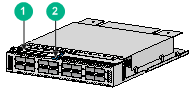
2. Unpack the interface card.
Figure 2 LSWM116Q interface card
|
(1) Ejector lever |
(2) Latch |
3. Press the latch on the card to release the ejector lever.
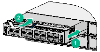
4. As shown by callout 1 in Figure 3, insert the card slowly into the slot along the guide rails.
5. Rotate inward the ejector lever as shown by callout 2 in Figure 3 until the latch locks the ejector lever in place.
Figure 3 Installing an LSWM116Q interface card
Removing the card
1. Prepare an anti-static bag.
2. Remove the cables from the card.
3. Press the latch to release the ejector lever
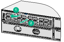
4. Rotate outward the ejector lever as shown by callout 1 in Figure 4.
5. Pull out the interface card slowly out of the interface card slot, as shown by callout 2 in Figure 4.
6. Place the removed interface card in the anti-static bag.
7. If you are not to install a new card, install a filler panel in the slot to prevent dust and ensure good ventilation in the device.
Figure 4 Removing an LSWM116Q interface card
Installing and removing QSFP+ transceiver modules or cables
For information about installing and removing QSFP+ transceiver modules and cables, see H3C Transceiver Modules and Network Cables Installation Guide at www.h3c.com.
Verifying the installation
After the installation is complete, determine whether the card is operating correctly.
If the card fails to operate correctly, perform the following steps:
1. Reinstall the card following the installation procedures described in this document.
2. If the problem persists, contact H3C Support.
▌Technical support
New H3C Technologies Co., Ltd. provides customers with comprehensive technical support and service. If you purchase the products from the sales agent of New H3C Technologies Co., Ltd., please contact our sales agent or technical personnel.
Website: http://www.h3c.com
