- Released At: 19-12-2021
- Page Views:
- Downloads:
- Table of Contents
- Related Documents
-
H3C Virtual AP Technology White Paper
Copyright © 2021 New H3C Technologies Co., Ltd. All rights reserved.
No part of this manual may be reproduced or transmitted in any form or by any means without prior written consent of New H3C Technologies Co., Ltd.
Except for the trademarks of New H3C Technologies Co., Ltd., any trademarks that may be mentioned in this document are the property of their respective owners.
This document provides generic technical information, some of which might not be applicable to your products.
The information in this document is subject to change without notice.
Contents
Overview
Technical background
The following solutions are available:
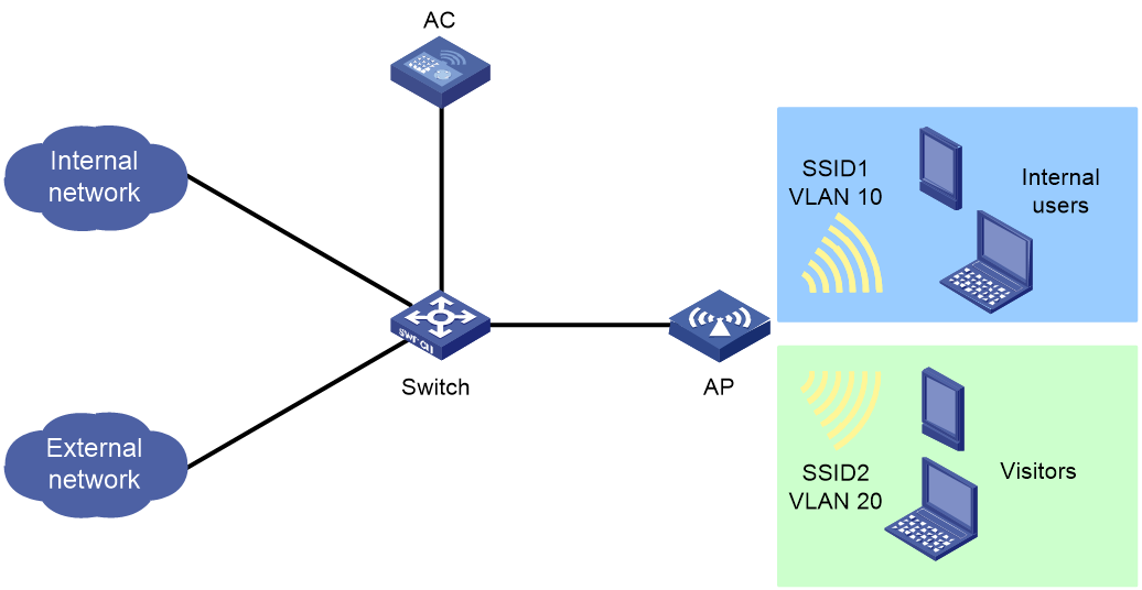
· Traditional logical isolation
In this solution, one AC is deployed to manage both networks and perform VLAN-based service isolation. Internal and external resources cannot be fully isolated and security issues might occur.
Figure 1 Traditional logical isolation
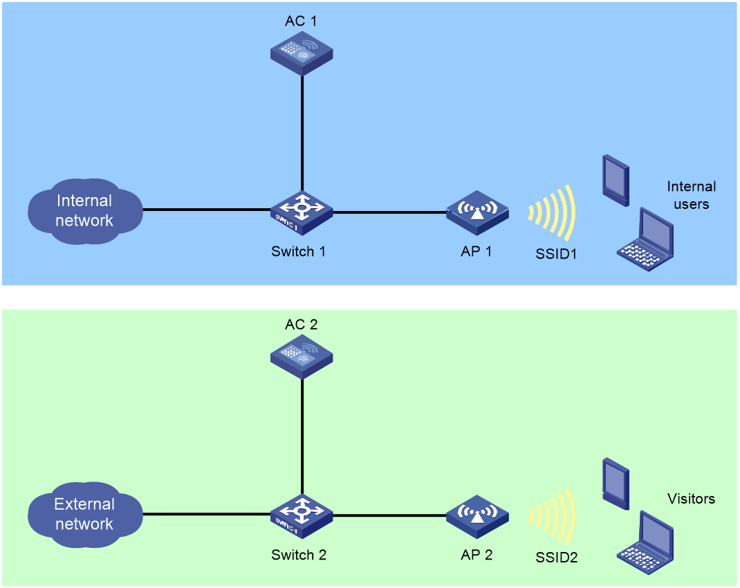
· Physical isolation
A set of AC and APs are deployed for each network to completely isolate the two networks. This solution increases the deployment cost.
Figure 2 Physical isolation
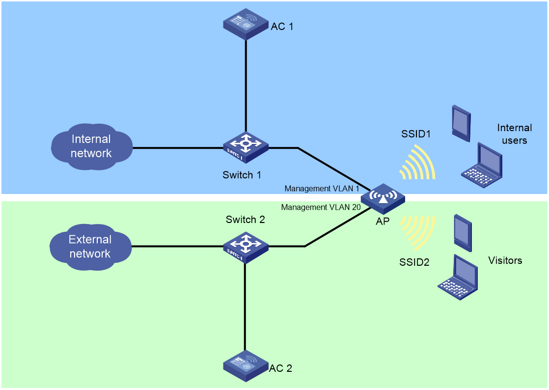
· H3C internal and external network isolation
One AC is deployed for internal access and the other AC is deployed for external access to control one set of APs. This solution can implement physical isolation and save costs.
Figure 3 H3C internal and external network isolation
Benefits
Reduced deployment cost
Without deploying more physical APs, you can create virtual APs for existing physical APs to support multiple sets of isolated WLANs. Virtual APs do not require licenses, which further reduces the WLAN deployment cost.
Resource isolation
With one virtual AP and one physical AP managed by different ACs, internal traffic and external traffic can be isolated from each other. This avoids network resource conflicts and ensures that the internal and external network services do not affect each other.
Virtual AP implementation
Virtual AP networking
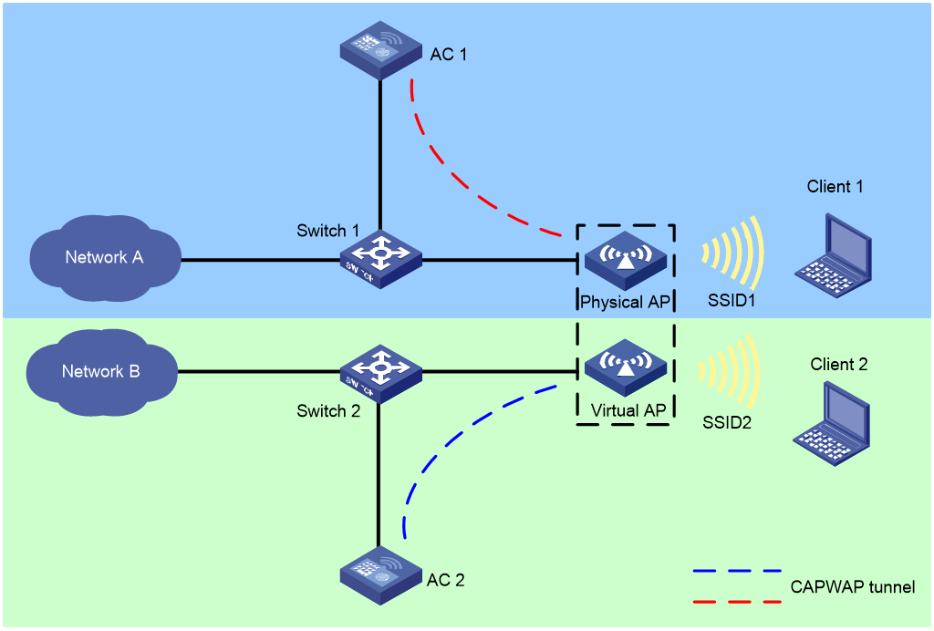
As shown in Figure 4, install AP licenses on AC 1, configure the physical AP to establish a CAPWAP tunnel with AC 1 through Ethernet interface 1. Create a virtual AP for the physical AP, and configure the virtual AP to establish a CAPWAP tunnel with AC 2 through Ethernet interface 2. Use AC 1 and AC 2 to manage the physical AP and virtual AP, respectively. Then, the two WLANs can provide isolated wireless services to different users.
Figure 4 Virtual AP networking
Mechanism
Virtual AP creation
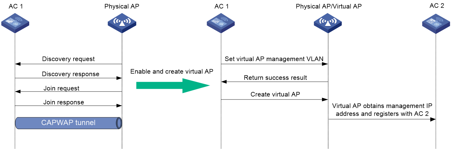
As shown in Figure 5, to create a virtual AP, first onboard the physical AP, enable the virtual AP feature, create a virtual AP, and specify the IP address of the AC to which the AP connects. Then, a virtual AP is created as follows:
1. The AC specifies the management VLAN for the virtual AP.
2. The AC configures the management VLAN to obtain IP address settings through DHCP.
3. The AC creates the virtual AP on the physical AP.
4. The virtual AP obtains the IP address of the management VLAN, and then registers with AC 2.
If the AP fails to obtain the management VLAN IP address, it creates a timer and keeps trying until the timer expires.
Figure 5 Creating a virtual AP
Virtual AP association
|
|
IMPORTANT: If software upgrade is enabled and a virtual AP uses a different version from an AC, the AP cannot come online from the AC. In this case, disable software upgrade first. |
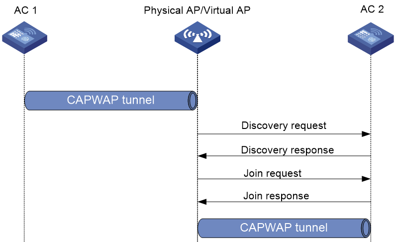
After the physical AP creates a data block and obtains the management VLAN IP for the virtual AP, the AP enters the CAPWAP state machine and starts to register with AC 2 as follows:
1. Upon receiving a Discovery Request, AC 2 determines whether to send a Discovery Response based on the AP model and capabilities.
2. Upon receiving a Join Request, AC 2 identifies if there is an AP template matching information (including AP SN) in the request.
¡ If a match is found, the AC returns a Join Response.
¡ If no match is found, the AC does not respond to the virtual AP.
3. The virtual AP requests to download configurations at the CAPWAP configuration downloading phase.
4. The virtual AP comes online from AC 2.
Figure 6 Virtual AP association
Restrictions and guidelines
· You can create a maximum of one virtual AP for a physical AP.
· Virtual APs do not support the auto AP feature.
· Make sure the IP address of the AC that manages a physical AP is different from the IP address of the AC that manages its virtual AP and make sure the IP addresses are the same version.
· A virtual AP can operate correctly only when its physical AP operates correctly. Make sure the physical AP is in normal state. For example, if the physical AP is disconnected from its AC, the virtual AP will also be disconnected.
Application scenarios
Common virtual AP networking
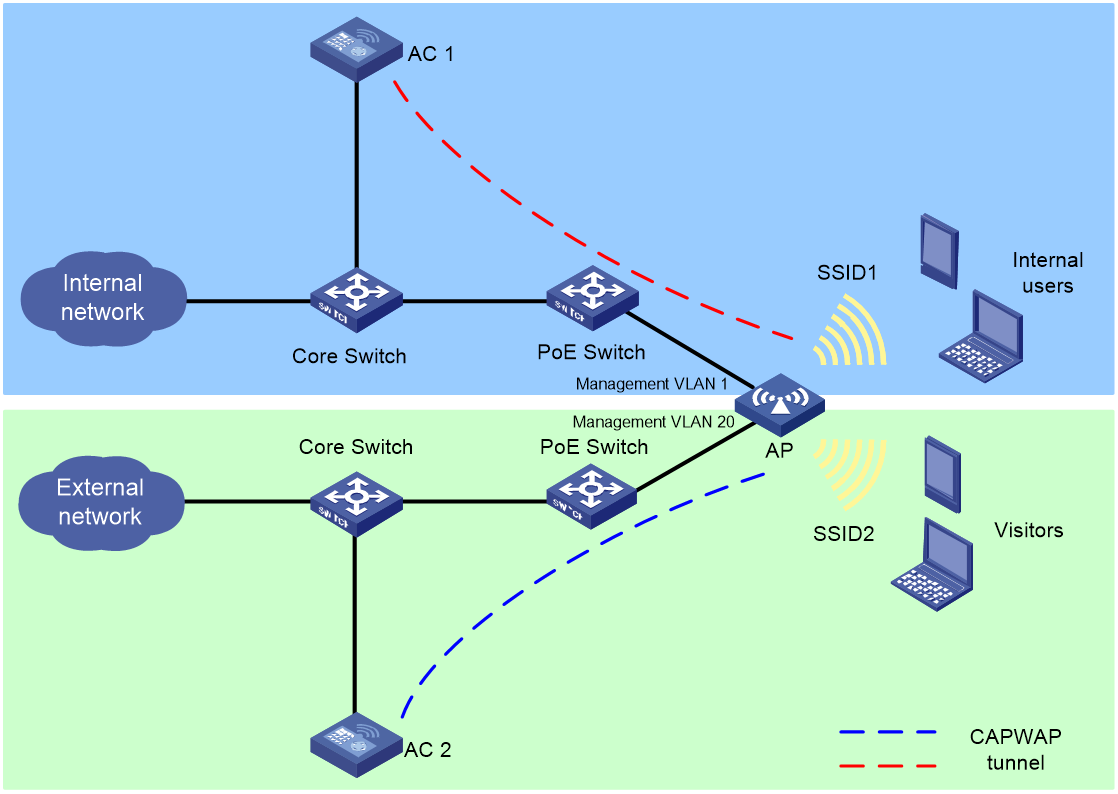
As shown in Figure 7, the AP connects to the internal network and external network through different uplink interfaces and each network is deployed with an AC.
· Create a virtual AP for the physical AP and configure AC 1 and AC 2 to manage the physical AP and virtual AP, respectively.
· Configure the physical AP to provide wireless services with SSID 1 for internal users and the virtual AP to provide wireless services with SSID 2 for visitors in the external network.
· Enable seamless roaming in the internal network and enable portal authentication in the external network.
Figure 7 Common virtual AP networking
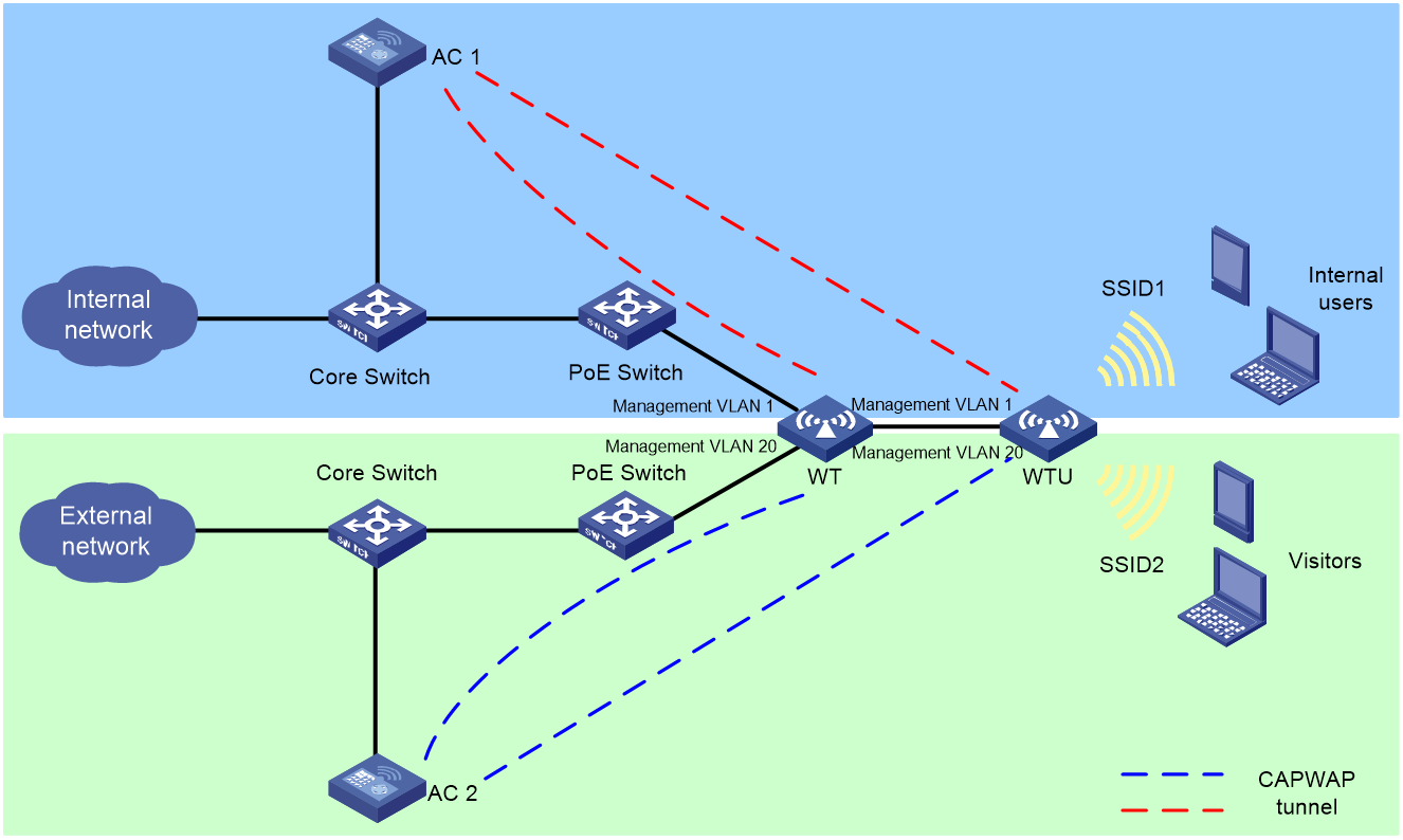
Virtual WT and WTU networking
As shown in Figure 8, the WT connects to the internal network and external network through different uplink interfaces and each network is deployed with an AC.
· Create a virtual WT and a virtual WTU, and configure AC 1 and AC 2 to manage the physical devices and virtual devices, respectively. The WTs and WTUs establish CAPWAP tunnels with both ACs.
· Configure the physical WTU to provide wireless services with SSID 1 for internal users and the virtual WTU to provide wireless services with SSID 2 for visitors in the external network.
· Enable seamless roaming in the internal network and enable portal authentication in the external network.
Figure 8 Virtual WT and WTU networking