| Title | Size | Downloads |
|---|---|---|
| Universal Cabinet and Accessories Installation Guide-6W101-book.pdf | 6.08 MB |
- Table of Contents
- Related Documents
-
Universal Cabinet and Accessories
Installation Guide
Document version: 6W101-20211109
Copyright © 2021 New H3C Technologies Co., Ltd. All rights reserved.
No part of this manual may be reproduced or transmitted in any form or by any means without prior written consent of New H3C Technologies Co., Ltd.
Except for the trademarks of New H3C Technologies Co., Ltd., any trademarks that may be mentioned in this document are the property of their respective owners.
The information in this document is subject to change without notice.
Contents
47U DP type network cabinet and 42U DP type server cabinet
3 Installing the cabinet on a concrete floor
Determining installation hole locations
Performing the insulation resistance test
4 Installing the cabinet on an anti-static floor
Assembling the DP cabinet support
Determining the hole locations for the DP cabinet support
Determining the hole locations by using the cabinet floor plan
Determining the hole locations by using the drill hole template
Attaching the DP cabinet support to the ground
Installing the cabinet on the DP cabinet support
Performing the insulation resistance test
6 Installing cabinet accessories
Installing the cabinet bottom panel
Installing a DC input terminal block
Installing power distribution units
7 Removing and installing cabinet doors
8 Installing and replacing foam air filters
1 Overview
H3C provides the following 19-inch cabinets that comply with IEC-60297-3-100, GB/T 19520.16, and EIA-310-D standards.
|
Cabinet name |
Cabinet model |
Dimensions (H × W × D) |
Remarks |
|
47U DP type network cabinet |
RACK-47U612-NA |
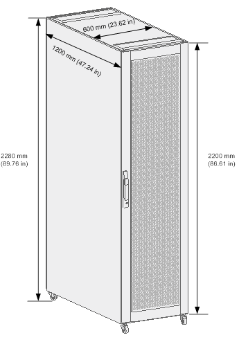
2200 × 600 × 1200 mm (86.61 × 23.62 × 47.24 in) |
The height excludes the casters. |
|
42U68 DP type network cabinet |
RACK-42U68-NA |
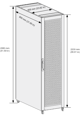
2200 × 600 × 800 mm (86.61 × 23.62 × 31.50 in) |
The height excludes the casters. |
|
42U DP type server cabinet |
RACK-DP42U612-SA |
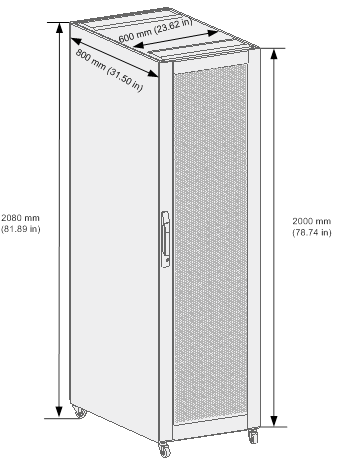
2200 × 600 × 1200 mm (86.61 × 23.62 × 47.24 in) |
The height excludes the casters. |
The cabinets can be assembled and have the following features:
· You can adjust the distance between the front and rear cabinet posts in increments of 25 mm (0.98 in).
· The static load capacity of the cabinet is 1000 kg (2204.59 lb). The omnidirectional wheels installed at the bottom facilitate cabinet moving and allow you to move the cabinet over a ramp with an angle smaller than or equal to 10 degrees.
· With perforated doors installed at the front and rear of the cabinet, the cabinet supports front-to-rear airflow with the ventilation rate greater than 80%.
Cabinet views
47U DP type network cabinet
Figure1-1 47U DP type network cabinet view
42U68 DP type network cabinet
Figure1-2 42U68 DP type network cabinet view
42U DP type server cabinet
Figure1-3 42U DP type server cabinet
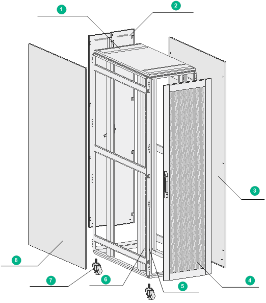
Cabinet structure
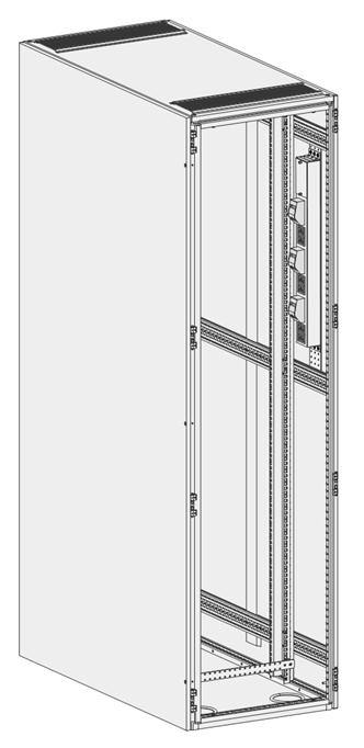
The structures of the 47U DP type network cabinet and 42U68 DP type network cabinet are similar. The following uses the 47U DP type network cabinet for illustration.
Figure1-4 Cabinet structure (47U DP type network cabinet)
|
(1) Top cover |
(2) Rear cabinet door |
|
(3) Right cabinet door |
(4) Front cabinet door |
|
(5) Cabinet frame |
(6) Cabinet post |
|
(7) Caster |
(8) Left cabinet door |
2 Preparing for installation
Space
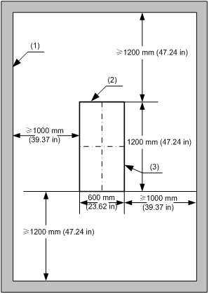
To facilitate servicing, plan and reserve enough clearance around the cabinet.
You can use a 47U DP type network cabinet in standalone or join multiple 47U DP type network cabinets into a suite. You can use a 42U DP type server cabinet in standalone or join multiple 42U DP type server cabinets into a suite. A 42U68 DP type network cabinet can only be used in standalone.
The space requirements for a 47U DP type network cabinet and a 42U DP type server cabinet is similar.
47U DP type network cabinet and 42U DP type server cabinet
Figure2-1 Space requirements for a standalone 47U DP type network cabinet or 42U DP type server cabinet
|
(1) Interior wall or object for reference |
(2) Cabinet rear |
(3) Cabinet outline |
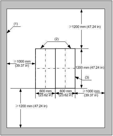
Figure2-2 Space requirements for two 47U DP type network cabinets or 42U DP type server cabinets in a suite
|
(1) Interior wall or object for reference |
(2) Cabinet rear |
(3) Cabinet outline |
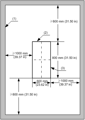
42U68 DP type network cabinet
Figure2-3 Space requirements for a standalone 42U68 DP type network cabinet
|
(1) Interior wall or object for reference |
(2) Cabinet rear |
(3) Cabinet outline |
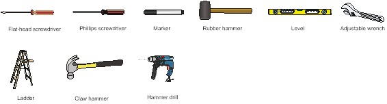
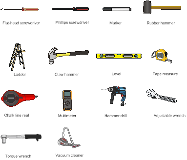
Installation tools
When installing the cabinet, you might need the following tools as shown in Figure2-4.
3 Installing the cabinet on a concrete floor
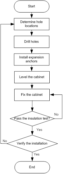
Installation flowchart
Figure3-1 Installation flowchart
Determining installation hole locations
1. According to the cabinet locations on the equipment room floor plan and the cabinet's levelling feet locations, determine the cabinet installation hole locations.
2. Use a tap measure to locate several points and draw two lines parallel to the wall or reference object.
3. Identify and mark the first expansion anchor installation hole and levelling foot location on the lines as designed.
4. Identify and mark the other expansion anchor installation hole and levelling feet locations.
5. Measure and verify the hole distance.
Figure3-2 Installation hole locations for a standalone 47U DP type network cabinet or 42U DP type server cabinet
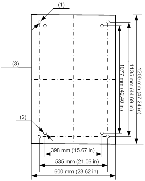
|
(1) Levelling foot location |
(2) Expansion anchor installation hole location |
(3) Cabinet outline |
Figure3-3 Installation hole locations for a 42U68 DP type network cabinet

|
(1) Levelling foot location |
(2) Location of expansion anchor installation hole |
(3) Cabinet outline |
Figure3-4 Installation hole locations for two 47U DP type network cabinets or 42U DP type server cabinets in a suite
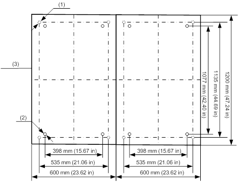
|
(1) Levelling foot location |
(2) Location of expansion anchor installation hole |
(3) Cabinet outline |
Drilling holes
|
|
CAUTION: · For a sturdy and slippery concrete floor, use a punch to create a hole to help locate the drill bit. · Keep the drill bit perpendicular to the ground and hold the drill handle tightly with both hands when drilling holes. · Make sure the depths of four holes are the same. |
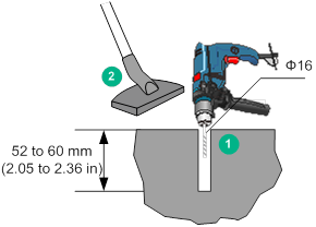
To drill holes on the concrete floor:
1. Use a hammer drill with a Ф16 mm (0.63 in) drill bit to drill four holes with a depth of 52 to 60 mm (2.05 to 2.36 in) at the marked locations.
2. Use a vacuum cleaner to vacuum the dust in or around the holes, as shown in Figure3-5.
Installing expansion anchors
|
|
CAUTION: · To install and fasten the expansion anchor properly, first insert the expansion wedges into the guide grooves. · Tap an expansion anchor into a hole until the expansion sleeve is fully inserted into the hole. |
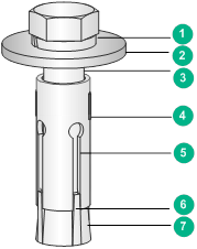
Figure3-6 Expansion anchor
|
(1) Spring washer |
(2) Flat washer |
|
(3) Bolt |
(4) Expansion sleeve |
|
(5) Guide groove |
(6) Expansion wedge |
|
(7) Expansion cone |
|
To install an expansion anchor:
1. Turn the spring washer, flat washer, and bolt clockwise until the expansion wedges cannot be pulled out of the guide groove completely.
2. Vertically insert the expansion anchor into the hole and tap the expansion anchor with a claw hammer until the expansion sleeve is fully inserted into the hole, as shown in Figure3-7.
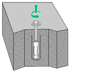
3. Use a wrench to fasten the expansion anchor until the expansion anchor is fully expanded.
4. Remove the spring washer, flat washer, and bolt, as shown in Figure3-8.
Figure3-7 Installing an expansion anchor
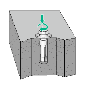
Figure3-8 Removing the spring washer, flat washer, and bolt
Leveling the cabinet
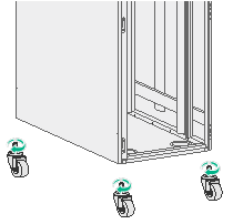
1. Move the cabinet to the planned location by using the casters.
2. Remove the casters from the cabinet, as shown in Figure3-9.
Figure3-9 Removing the casters from the cabinet
3. Attach the levelling feet to the cabinet bottom, as shown in Figure3-10.
Figure3-10 Installing levelling feet
4. Align the levelling feet of the cabinet with the levelling foot location marked on the ground.
Figure3-11 Installation hole locations
|
(1) Levelling foot location |
(2) Expansion anchor installation hole location |
(3) Cabinet outline |
5. Place levels on the cabinet top cover in two mutually perpendicular directions. If the cabinet is not level, use an adjustment wrench to adjust the levelling feet.
Fixing the cabinet
Use stabilizer brackets to fix the cabinet to the concrete floor. A stabilizer bracket is composed of a stabilizer and an expansion anchor.
Figure3-12 Stabilizer bracket
|
(1) Nut |
(2) Spring washer |
|
(3) Flat washer |
(4) Stabilizer |
|
(5) Expansion cone |
(6) Expansion sleeve |
|
(7) Stabilizer hole |
(8) Stabilizer groove |
To fix the cabinet:
1. As shown in Figure3-13, attach stabilizers to the levelling foot.
Four stabilizers are required for fixing a cabinet.
Figure3-13 Installing stabilizers
2. Align the stabilizer holes with the expansion anchor holes on the ground and then insert the expansion anchors into the expansion anchor holes.
3. Fasten the expansion anchors to a torque of 50 Nm by using a torque wrench.
Performing the insulation resistance test
Select the megohm range for the multimeter and then measure the resistance between a stabilizer and its expansion anchor.
· If the measured resistance is greater than 5 megohms, the installation meets the insulation requirements.
· If the resistance is no greater than 5 megohms, perform the following steps:
a. Remove all stabilizer brackets to check whether all insulation sleeves or insulation pads are installed or whether the insulation parts are damaged.
b. Reinstall the stabilizer bracket and repeat the insulation resistance test.
Verify the installation
After the installation, make sure the cabinet meets the following requirements:
· The cabinet arrangement, installation locations, and orientations meet the requirements of the engineering design plan.
· Each cabinet is perpendicular to the ground in all directions. The horizontal or vertical deviation must not be greater than 3 mm (0.12 in).
· The cabinets alongside the main aisle are aligned with the deviation of no more than 5 mm (0.20 in). The cabinets in rows are aligned closely, neatly and properly.
4 Installing the cabinet on an anti-static floor
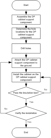
Installation flowchart
Figure4-1 Installation flowchart
DP cabinet support
To facilitate flooring and wiring in the equipment room, you need to elevate the cabinets. If no steel supports exist in the equipment room, you can purchase DP cabinet supports as required.
Views
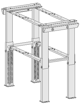
The H3C universal cabinets currently support the RACK-CE-DP-A, RACK-CE-DP-B, and RACK-CE-DP-C DP cabinet supports, as shown in Figure4-2, Figure4-3, and Figure4-4, respectively.
Figure4-2 RACK-CE-DP-A DP cabinet support
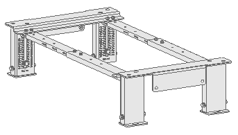
Figure4-3 RACK-CE-DP-B DP cabinet support
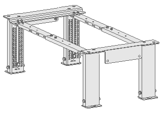
Figure4-4 RACK-CE-DP-C DP cabinet support
Technical specifications
Table4-1 Technical specifications
|
DP cabinet support model |
Compatible antistatic floor height |
DP cabinet support width |
Compatible cabinet depth |
|
RACK-CE-DP-A |
270 to 410 mm (10.63 to 16.14 in) |
600 mm (23.62 in) |
800 mm (31.50 in) 1000 mm (39.37 in) 1100 mm (43.31 in) 1200 mm (47.24 in) |
|
RACK-CE-DP-B |
410 to 700 mm (16.14 to 27.56 in) |
||
|
RACK-CE-DP-C |
700 to 1200 mm (27.56 to 47.24 in) |
|
|
NOTE: The only difference between different DP cabinet brackets is the compatible antistatic floor height. The following procedures in this chapter use the RACK-CE-DP-A DP cabinet support for illustration. |
Assembling the DP cabinet support
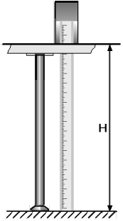
1. Measure the distance between the concrete floor and the upper surface of the antistatic floor with a ruler.
Figure4-5 Measuring the antistatic floor height
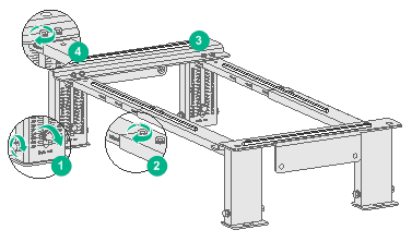
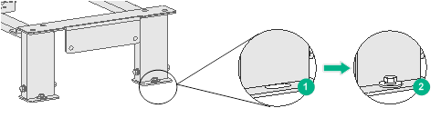
2. Adjust the height of the DP cabinet support based on the measured height, and then pre-fasten the height locking bolts, as shown by callout 1 in Figure4-6.
3. Adjust the depth of the DP cabinet support based on the cabinet depth, and fasten the bolts on the telescopic rods with a torque wrench to a torque of 13 Nm. See callout 2 in Figure4-6.
4. Use a level to check whether the DP cabinet support is level, as shown by callout 3 in Figure4-6.
If the DP cabinet support is not level, loosen the height locking bolts and adjust the height of the DP cabinet support, as shown by callout 4 in Figure4-6.
5. Fasten the height locking bolts to a torque of 50 Nm by using a torque wrench.
Figure4-6 Assembling the DP cabinet support
Determining the hole locations for the DP cabinet support
Determining the hole locations by using the cabinet floor plan
1. According to the cabinet floor plan and DP cabinet support dimensions, determine the installation location for a DP cabinet support.
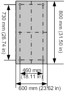
2. Use a tap measure to locate several points and then draw two lines spaced at 460 mm (18.11 in) parallel to the wall or reference object.
3. Identify and mark the first expansion anchor installation hole on the lines as designed.
4. Identify and mark the other expansion anchor installation hole locations.
5. Place the DP cabinet support on the ground to verify the hole locations and hole distance.
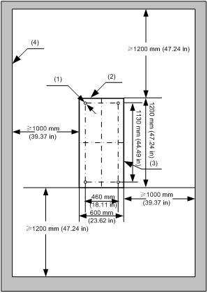
Figure4-7 Installation hole locations for a 47U DP type network cabinet support or a 42U DP type server cabinet support
|
(1) Installation hole location for the DP cabinet support |
(2) Cabinet rear |
|
(3) Cabinet outline |
(4) Interior wall or object for reference |
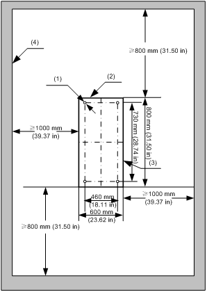
Figure4-8 Installation hole locations for a 42U68 DP type network cabinet support
|
(1) Installation hole location for the DP cabinet support |
(2) Cabinet rear |
|
(3) Cabinet outline |
(4) Interior wall or object for reference |
Determining the hole locations by using the drill hole template
1. Place the drill hole template at the planned installation location for the DP cabinet support on the ground.
2. Mark the installation holes for expansion anchors on the ground according to the template.
Figure4-9 Drill hole template for a 47U DP type network cabinet support or a 42U DP type server cabinet support
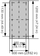
Figure4-10 Drill hole template for a 42U68 DP type network cabinet support
Drilling holes
For more information, see "Drilling holes."
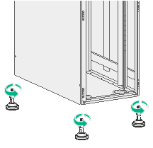
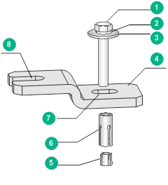
Attaching the DP cabinet support to the ground
1. Align the holes of the DP cabinet support with the expansion anchor holes on the concrete floor.
2. Take out the bolt, spring washer, and flat washer out of the expansion anchor accessory kit, and assemble the four expansion anchors.
3. Insert the expansion anchors into the expansion anchor holes on the ground, as shown in Figure4-11.
4. Fasten the four expansion anchors to a torque of 50 N-m by using a torque wrench.
Figure4-11 Attaching the DP cabinet support to the ground
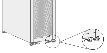
Installing the cabinet on the DP cabinet support
|
|
CAUTION: Stagger the bolt fastening to reduce the stress between the bolts and the cabinet. |
|
|
IMPORTANT: If a cabinet support from another vendor than H3C is used, drill four cabinet mounting holes each with a diameter of 14 mm (0.55 in) in the support and prepare M12 bolts. For the locations of the cabinet mounting holes, see the levelling foot locations in "Determining installation hole locations." |
To install the cabinet on the DP cabinet support:
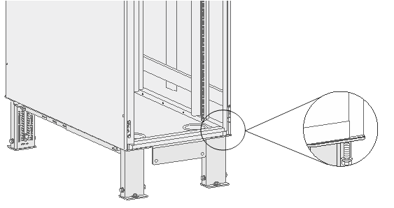
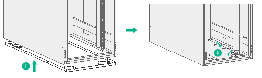
1. Lift the cabinet and place it on the DP cabinet support with the installation holes on the cabinet in alignment with that on the DP cabinet support. See Figure4-12.
Use multiple persons to lift the cabinet.
2. Take out the spring washer and flat washer out of the expansion anchor accessory kit, and assemble the four sets of M12 bolts, spring washers, and flat washers.
3. Insert the expansion anchors into the cabinet installation holes through the installation holes in the DP cabinet support, as shown in Figure4-12.
4. Fasten the expansion anchors in a staggered manner to a torque of 50 Nm by using a torque wrench.
Figure4-12 Installing the cabinet on the DP cabinet support
Performing the insulation resistance test
Select the megohm range for the multimeter and then measure the resistance between a DP cabinet support and the cabinet.
· If the measured resistance is greater than 5 megohms, the installation meets the insulation requirements.
· If the resistance is no greater than 5 megohms, perform the following steps:
a. Remove the DP cabinet support to check whether all insulation parts are installed or whether the insulation parts are damaged.
b. Attach the cabinet to the DP cabinet support again and then repeat the insulation resistance test.
Verify the installation
After the installation, make sure the cabinet meets the following requirements:
· The cabinets are placed according to the engineering design plan.
· The bolts for securing between the DP cabinet support and the ground and between the DP cabinet support and the cabinet are installed correctly. The spring washers and flat washers are installed in the correct order.
· The cabinets are aligned closely and neatly with a vertical deviation of less than 3 mm (0.12 in).
· With the cabinet doors installed, the cabinets alongside the main aisle are aligned with a deviation of less than 5 mm (0.20 in).
· The bolts in the cabinet are installed with flat washers and spring washers and the bolts are fastened.
· No deformation exists on the components of the cabinet.
5 Grounding the cabinet
1. Connect the grounding cable of the device and the cabinet to the grounding strip in the cabinet.
The cabinet comes with a grounding strip installed on it.
2. Connect the grounding strip in the cabinet to the grounding strip in the equipment room.
Figure5-2 Grounding strip
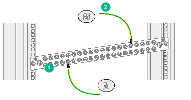
|
(1) Grounding strip |
(2) Grounding cable |
6 Installing cabinet accessories
Installation tools
When installing the cabinet accessories, you might need the following tools as shown in Figure6-1.
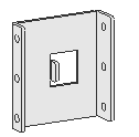
Installing the cabinet bottom panel
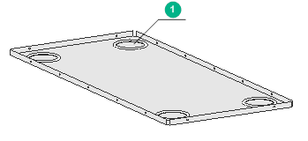
You can use the cabinet bottom panel to close the air duct at the cabinet bottom, as shown in Figure6-2. Four cable holes with a diameter of 100 mm (3.94 in) are reserved in the cabinet bottom panel for threading cables. The holes are covered by hole plugs.
Figure6-2 Cabinet bottom panel
|
(1) Cable hole |
To install the cabinet bottom panel:
1. Press the bottom panel into the cabinet bottom, with the installation holes in the bottom panel aligning with that in the cabinet frames, as shown in Figure6-3.
2. Insert the Phillips screws into the installation holes and use a Phillips screwdriver to fasten the Phillips screws.
Figure6-3 Installing the cabinet bottom panel
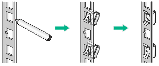
Installing rack panels
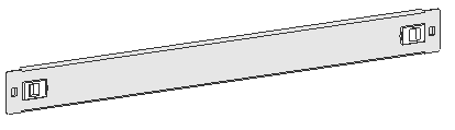
You can use the rack panels to fill the empty U-spaces of the rack. Rack panels support quick installation without using screws. The rack panels are divided into 1U rack panel and 2U rack panel, as shown in Figure6-4 and Figure6-5, respectively.
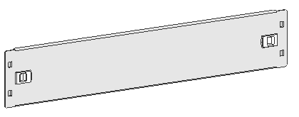
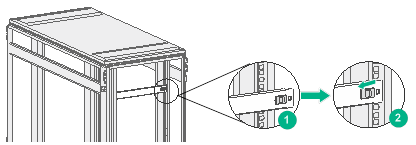
To install a rack panel:
1. Determine the rack panel installation location on the cabinet posts. A 1U and 2U rack panel occupies one and two RU space, respectively.
2. Holding the rack panel with both hands, align the projections with the square holes in the cabinet posts and press the rack panel until the plastic locking tabs lock in position.
Figure6-6 Installing the rack panel
Joining cabinets into a suite
To join two or more cabinets into a suite, you need to use joining plates and baying clamps, as shown in Figure6-7 and Figure6-8, respectively. The 47U DP type network cabinet and 42U DP type server cabinet support the RACK-CNT-DPBC-1 and RACK-BC-DP62421225 joining plates, respectively. The two joining plates are different in dimensions but the installation method for them is similar.
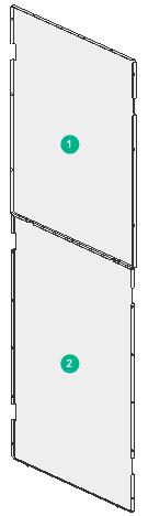
|
(1) Upper joining plate |
(2) Lower joining plate |
To join cabinets into a suite:
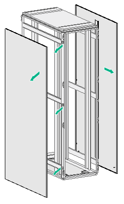
1. Use a Phillips screwdriver to remove the fastening screws on the side panels of the cabinet, and then remove the side panels and 12 hinges, as shown in Figure6-9.
To join two cabinets into a suite, remove the left panel from the cabinet at the right and the right panel from the cabinet at the left.
Figure6-9 Removing the side panels
2. Install the joining plates to one side of the cabinet, as shown by callout 1 in Figure6-10.
3. Fix the cabinets to the DP cabinet supports or the concrete floor, as shown by callout 2 in Figure6-10.
4. At the blank space of the joining plates, align the installation holes in the baying clamps with installation holes in the cabinet frames of the cabinets at both sides.
5. Insert the M5 Phillips pan head self tapping screws into the holes and fasten the screws.
Figure6-10 Joining cabinets into a suite
Installing slide rails
For information about installing H3C 1U adjustable slide rails, see H3C LSXM1BSR 1U Bottom-Support Rails Installation Guide.
For information about installing H3C 2U adjustable slide rails, see H3C 2RU Slide Rails Installation Guide.
For more information about installing H3C LSVM1BSR10 slide rails, see H3C LSVM1BSR10 Adjustable Slide Rails Installation Guide.
Installing a DC input terminal block
For more information about installing a DC input terminal block, see H3C S12500-X DC Input Terminal Block User Manual.
Installing power distribution units
PDUs
Power distribution units (PDUs) in the cabinet enable secure, reliable, and neat power distribution and professional power supply maintenance.
The four PDUs P111-32X-4E2G-D, PDU-96A-6C19, P411-32X-4G-D1, and P411-32X-10E2G-D1 are available for your choice.
P111-32X-4E2G-D
You can install a required number of P111-32X-4E2G-D PDUs on a standard 19-inch cabinet as needed.
Figure6-11 P111-32X-4E2G-D view
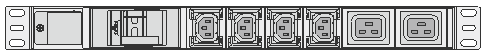
Table6-1 Technical specifications
|
Item |
Description |
|
Connector |
· 4 × C13 connectors · 2 × C19 connectors |
|
Max output current of a connector |
· C13: 10 A · C19: 16 A |
|
Max current capacity of the PDU |
32 A |
PDU-96A-6C19
You can install a maximum of four PDU-96A-6C19 PDUs on a standard 19-inch cabinet. You can use PDU brackets to install the PDU vertically on the cabinet.
Figure6-12 PDU-96A-6C19 view

Table6-2 Technical specifications
|
Item |
Description |
|
Connector |
6 × C19 connectors |
|
Max output current of a connector |
16 A |
|
Max current capacity of the PDU |
96 A |
P411-32X-4G-D1
You can install a required number of P411-32X-4G-D1 PDUs on a standard 19-inch cabinets as needed.
Figure6-13 P411-32X-4G-D1 view
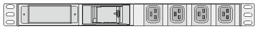
Table6-3 Technical specifications
|
Item |
Description |
|
Connector |
4 × C19 connectors |
|
Max output current of a connector |
16 A |
|
Max current capacity of the PDU |
32 A |
P411-32X-10E2G-D1
You can install a required number of P411-32X-10E2G-D1 PDUs on a standard 19-inch cabinet as needed. You can use PDU brackets to install the PDU vertically on the cabinet.
Figure6-14 P411-32X-10E2G-D1 view
![]()
Table6-4 Technical specifications
|
Item |
Description |
|
Connector |
· 10 × C13 connectors · 2 × C19 connectors |
|
Max output current of a connector |
· C13: 10 A · C19: 16 A |
|
Max current capacity of the PDU |
64 A |
Installing PDUs
|
|
WARNING! Before installing PDUs, make sure all switches of the external power supply devices are off. |
|
|
CAUTION: · Determine the locations for the PDU brackets on the cabinet posts according to the PDU height. · If you install a PDU vertically on a cabinet, make sure the PDU does not cross the cabinet beam. · To install a PDU vertically on a cabinet, make sure the distance between installation holes of the upper and lower PDU brackets is greater than the PDU height. |
Installing PDUs horizontally
The P111-32X-4E2G-D PDUs and P411-32X-4G-D1 PDUs can be installed horizontally and the installation procedure is similar for them. The following installs P111-32X-4E2G-D PDUs horizontally.
To install a PDU horizontally:
1. Determine the PDU installation location on the cabinet posts.
2. Mark the PDU location on the cabinet posts and install cage nuts in all marked square holes, as shown in Figure6-15.
Figure6-15 Installing cage nuts
3. Align the upper and lower installation holes of each PDU mounting ear with the cage nut installation holes in the cabinet posts, and use two mounting screws to secure the PDU to the cabinet posts. See Figure6-16.
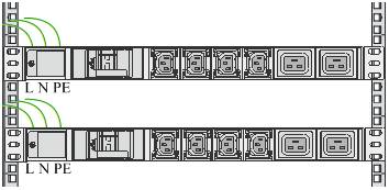
Reserve a minimum of 1U distance between two PDUs and connect the wires in the correct order, as shown in Figure6-17.
Figure6-16 Installing a P111-32X-4E2G-D PDU horizontally
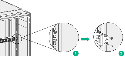
Figure6-17 Installing two P111-32X-4E2G-D PDUs horizontally
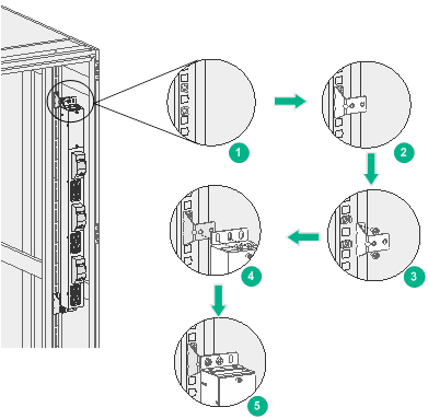
Installing a PDU vertically
The PDU-96A-6C19 PDUs and P411-32X-10E2G-D1 PDUs can be installed vertically and the installation procedure is similar for them. The following installs a PDU-96A-6C19 PDU vertically.
To install a PDU vertically on a cabinet post:
1. Determine the PDU bracket installation locations on the cabinet post.
2. Mark the PDU bracket installation locations on the cabinet post and install cage nuts in all marked square holes, as shown in Figure6-15.
3. Align the installation holes of each PDU bracket with the cage nut installation holes in the cabinet post, and use two mounting screws to secure the PDU bracket to the cabinet post.
If you need to use slide rails to install a device in the cabinet, beware of the PDU brackets in the cabinet posts.
4. Attach the PDU to the PDU brackets.
¡ To install the PDU on the right cabinet post, align the two left installation holes of the PDU with that in the PDU bracket and use screws to secure the PDU to the bracket. Then use the same method to secure the other end of the PDU to the cabinet.
¡ To install the PDU on the left cabinet post, align the two right installation holes of the PDU with that in the PDU bracket and use screws to secure the PDU to the bracket. Then use the same method to secure the other end of the PDU to the cabinet.
Figure6-18 Installing a PDU-96A-6C19 vertically on a cabinet post
To install a PDU on a side panel:
1. Determine and mark the PDU installation location on the side panel.
2. Align the PDU installation holes with the nut installation holes in the side panel, and use two mounting screws to secure one end of the PDU to the side panel. Then use the same method to secure the other end of the PDU to the side panel.
Figure6-19 Installing a PDU-96A-6C19 vertically on a side panel
7 Removing and installing cabinet doors
Removing cabinet doors
As a best practice, remove the front and rear doors from a cabinet before installing a large-sized device into the cabinet.
The removable procedure is the same for the front and rear cabinet doors. The following procedure removes the cabinet front door.
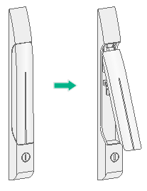
1. Insert the key into the lock on the cabinet door handle and turn the key clockwise until the handle is released automatically.
Figure7-1 Opening the cabinet door handle
2. Open the cabinet front door, and then remove the grounding cable.
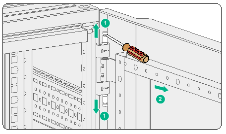
3. Use a screwdriver to pry out the upper and lower pins from each of the four hinges. Then remove the door.
Figure7-2 Removing the cabinet front door
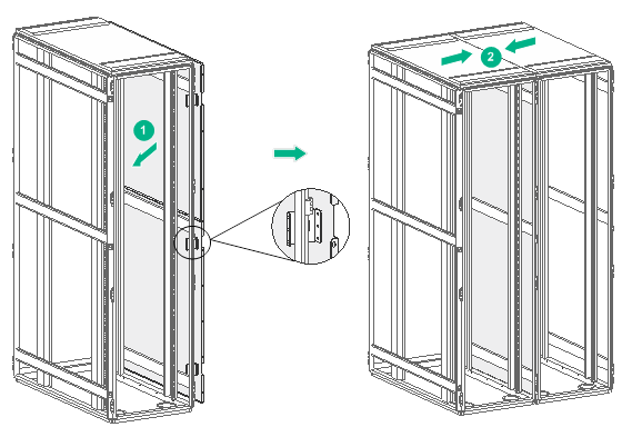
Installing cabinet doors
The installation procedure is the same for the front and rear cabinet doors. The following procedure installs the cabinet front door.
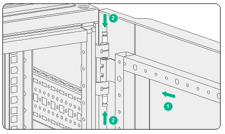
1. Place the door vertically in front of the cabinet, and line up the hole in each hinge bracket on the door with the holes in the hinge brackets on the cabinet.
2. Insert upper and lower pins into each of the four hinges.
Figure7-3 Installing the cabinet front door
3. Connect the grounding cable.
8 Installing and replacing foam air filters
This section is applicable to 47U DP type network cabinets. For the foam air filter installation procedure for a 42U DP type network cabinet or 42U DP server cabinet, see the foam air filter installation guide for the cabinet.
Table8-1 describes the foam air filter and clamp kit for the 47U DP type network cabinet.
Table8-1 Foam air filter and clamp kit for the 47U DP type network cabinet
|
BOM part No. |
Model |
Description |
|
2102A004 |
RACK-47U612-NA |
47U DP type network cabinet |
|
2110A08W |
AF-DUSTA |
Dustproof sponge ASM |
|
2150A0HJ |
RK-F01-DP CABINET |
DP cabinet foam air filter clamp kit |
Installing a foam air filter
The foam air filter is installed on the inner side of the cabinet front door.
To install a foam air filter:
1. Remove the cabinet front door. For the removal procedure, see "Removing cabinet doors."
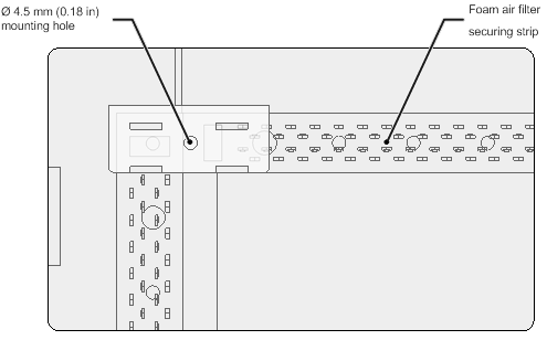
2. Paste foam air filter securing strips on the square bars on the inner side of the cabinet door, leaving 4.5 mm (0.18 in) mounting holes in the square bars uncovered for installing the foam air filter clamps.
Eight clamps are required for securing the foam air filter. As a best practice, leave one 4.5 mm (0.18 in) mounting hole at each of the four corners and two 4.5 mm (0.18 in) holes on the left and right square bars uncovered by the strips.
Figure8-1 Attaching foam air filter securing strips
3. Press the foam air filter onto the securing strips to cover the entire cabinet door, and cut off the excess parts with scissors.
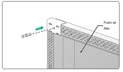
4. Press each foam air filter clamp against the foam air filter with the hole in the foam air filter clamp aligned with the exposed 4.5 mm (0.18 in) hole in square bars. Then use nylon rivets to secure the clamp to the square bar.
Figure8-2 Installing a foam air filter clamp
5. Installing the cabinet front door. For the installation procedure, see "Installing cabinet doors."
Replacing a foam air filter
Clean foam air filters regularly based on the cleanliness of the equipment room. As a best practice, clean foam air filters every three months and replace foam air filters every year.
To replace a foam air filter:
1. Remove the cabinet front door. For the removal procedure, see "Removing cabinet doors."
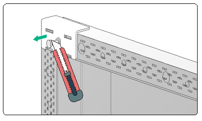
2. Use a knife to separate the two parts of the nylon rivet on each foam air filter clamp, and remove the nylon rivet and the clamp in sequence.
Figure8-3 Removing a foam air filter clamp
3. Pinch the edge of the foam air filter and slowly remove the air filter, taking care not to tear the air filter.
4. Install a clean and dry foam air filter on the cabinet door. For the installation procedure, see "Installing a foam air filter."
9 Obtaining documentation
To obtain the latest documentation, visit H3C website at http://www.h3c.com/en/Support/Resource_Center/Technical_Documents/.
