| Title | Size | Downloads |
|---|---|---|
| Mirroring on H3C DC Switches-6W100-book.pdf | 430.65 KB |
- Table of Contents
- Related Documents
-
Mirroring on H3C DC Switches
S6800 Switch Series R27xx
S6860 Switch Series R27xx
S6861 Switch Series R27xx
S6820 Switch Series R630x
S6805 Switch Series R66xx
S6825 Switch Series R66xx
S6850 Switch Series R655x, R66xx
S9850 Switch Series R655x, R66xx
S9820-64H Switch R655x, R66xx
S9820-8C Switch R66xx
S12500-X/S12500X-AF Switch Series (Type F Cards and Type H Cards) R27xx
S12500R/S12500CR Switch Series (Type K Cards) R511x
Document version: 6W100-20221026
|
Copyright © 2022 New H3C Technologies Co., Ltd. All rights reserved. No part of this manual may be reproduced or transmitted in any form or by any means without prior written consent of New H3C Technologies Co., Ltd. The information in this document is subject to change without notice. |
|
General restrictions and guidelines
Example: Configuring local port mirroring (SPAN)
Local port mirroring with multiple monitor ports implemented through remote probe VLAN
Example: Configuring local port mirroring with multiple monitor ports through remote probe VLAN
Layer 2 remote port mirroring (RSPAN)
RSPAN restrictions and guidelines
Layer 3 remote port mirroring (ERSPAN)
ERSPAN in encapsulation parameter mode
Hardware and port mirroring compatibility matrix
Flow mirroring to local interfaces (SPAN)
Example: Flow-mirroring traffic to local interfaces in interface mode
Example: Flow-mirroring traffic to local interfaces in monitoring group mode
Flow-mirroring to Layer 3 remote devices (ERSPAN)
Flow mirroring ERSPAN in interface mode and configuration examples
Flow mirroring to interfaces in loopback mode
Flow mirroring to interfaces in encapsulation parameter mode
Flow mirroring ERSPAN in monitoring group mode and configuration examples
Specifying encapsulation parameters for monitoring group members
Specifying tunnel interfaces as member ports
Hardware and flow mirroring compatibility matrix
Overview of mirroring
Introduction
Mirroring copies the specified packets to a port that connects to a data monitoring device for network monitoring and analysis.
Concepts
Mirroring source
A mirroring source is a monitored object. Mirroring sources include:
· Port—Copies the incoming or outgoing packets of a port (called source port) to the monitor ports.
· CPU—Copies the incoming or outgoing packets of a CPU (called source CPU) to the monitor ports.
· Data flow—Uses a QoS policy to match packets with the specified characteristics and copy them to the monitor ports.
Source device
The device where the mirroring sources reside is called a source device.
Monitor port
A monitor port connects to a data monitoring device. Mirrored packets are sent out monitor ports to the connected data monitoring devices.
Destination device
The device where the monitor ports reside is called a destination device.
Mirroring direction
The mirroring direction specifies the direction of packets copied on a mirroring source. Options include:
· Inbound—Copies packets received.
· Outbound—Copies packets sent.
· Both—Copies packets received and sent.
Mirroring group
A mirroring group contains mirroring sources and monitor ports. Mirroring groups include local mirroring groups, remote source groups, and remote destination groups.
Mirroring categories
Mirroring includes the following categories:
· Port mirroring—Copies packets of the specified ports or CPUs to the monitoring devices. For simplicity, this document describes only port mirroring with source ports.
· Flow mirroring—Uses a QoS policy to copy matching traffic to the monitoring devices.
Mirrored packet sampling
When configuring mirroring, you can specify a sampler to sample mirrored packets and thus reduce the number of mirrored packets. A sampler selects one packet from the specified number of packets. For information about sampler configuration, see Network Management and Monitoring Configuration Guide.
Support for mirrored packet sampling varies by device model. For more information, see “Hardware and port mirroring compatibility matrix” and ”Hardware and flow mirroring compatibility matrix.”
General restrictions and guidelines
As a best practice to ensure mirrored packet forwarding, configure mirroring on devices in the order of destination device, intermediate devices, and source device.
When planning the mirroring feature, avoid congestion on the monitor ports and reflector port. For example, do not mirror traffic of multiple 10-GE source ports to one 10-GE monitor port.
On an S12500-X, S12500X-AF, S12500R, or S12500CR switch, traffic is mirrored from multiple source ports to multiple monitor ports through multicast. In this case, a large number of mirrored packets exist on the switch. To avoid global packet loss, make sure the sum of mirrored packets and service packets do not exceed the forwarding capability of the switch.
Delete useless mirroring configuration from devices in time. Useless mirroring configuration might unexpectedly generate mirrored packets, which might cause network failures.
Port mirroring
Port mirroring types
Port mirroring includes the following types depending on whether the mirroring sources and mirroring destinations are on the same device:
· Local port mirroring—Also known as Switch Port Analyzer (SPAN). In local port mirroring, the source device is directly connected to data monitoring devices. The source device also acts as the destination device to forward mirrored packets to the data monitoring devices.
· Remote port mirroring—In remote port mirroring, the source device is not directly connected to data monitoring devices. The source device copies mirrored packets to the destination device, and then the destination device forwards them to the data monitoring devices.
Depending on how the source device and the destination device are connected, remote port mirroring includes the following types:
¡ Layer 2 remote port mirroring—Also known as Remote SPAN (RSPAN). The source device and destination device are connected through a Layer 2 network.
¡ Layer 3 remote port mirroring—Also known as Encapsulated Remote SPAN (ERSPAN). The source device and destination device are connected through a Layer 3 network.
Local port mirroring (SPAN)
Introduction
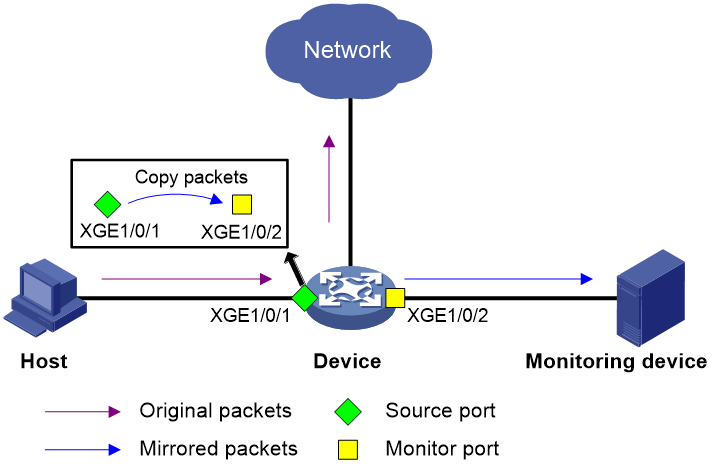
As shown in Figure 1, it is required to copy packets received on Ten-GigabitEthernet 1/0/1 to Ten-GigabitEthernet 1/0/2. Ten-GigabitEthernet 1/0/2 then forwards the packets to the data monitoring device for analysis. To meet this requirement, configure local port mirroring to mirror the incoming packets of source port Ten-GigabitEthernet 1/0/1 to monitor port Ten-GigabitEthernet 1/0/2.
Restrictions and guidelines
· The type F cards in S12500X-AF, S12500F-AF, and S9800 switch series do not support cross-card mirroring. The other switches and cards support cross-card mirroring.
· When configuring local port mirroring in source CPU mode, follow these restrictions and guidelines:
¡ All devices support mirroring the incoming packets of a source CPU.
¡ Only the type H cards and compatible MPUs in the S12500X-AF switch series support mirroring the outgoing packets of a source CPU.
· For mirroring to operate properly, do not enable the spanning tree protocol on any monitor port.
· Multiple source ports can be assigned to a mirroring group. However, a source port can be assigned to only one mirroring group.
· On the S12500-X/S12500X-AF switch series running version R26xx or later, the S12500R switch series, and the S12500CR switch series, you can configure multiple monitor ports in a mirroring group. On the other switches, you can configure only one monitor port in a mirroring group.
· For the data monitoring devices to analyze only mirrored packets, do not use the monitor ports for any other purpose.
Example: Configuring local port mirroring (SPAN)
# Create local mirroring group 1.
<Device> system-view
[Device] mirroring-group 1 local
# Configure local mirroring group 1 to mirror the incoming packets of source port Ten-GigabitEthernet 1/0/1 to monitor port Ten-GigabitEthernet 1/0/2.
[Device] mirroring-group 1 mirroring-port ten-gigabitethernet 1/0/1 Inbound
[Device] mirroring-group 1 monitor-port ten-gigabitethernet 1/0/2
# Disable the spanning tree protocol on monitor port Ten-GigabitEthernet 1/0/2.
[Device] interface ten-gigabitethernet 1/0/2
[Device-Ten-GigabitEthernet1/0/2] undo stp enable
[Device-Ten-GigabitEthernet1/0/2] quit
# Display configuration information of all mirroring groups.
[Device] display mirroring-group all
Mirroring group 1:
Type: Local
Status: Active
Mirroring port:
Ten-GigabitEthernet1/0/1 Inbound
Monitor port: Ten-GigabitEthernet1/0/2
Local port mirroring with multiple monitor ports implemented through remote probe VLAN
Introduction
On S6800 and S6850 switches, which do not support configuring multiple monitor ports in a local mirroring group, you can achieve this purpose by remote probe VLAN. On S12500-X, S12500X-AF, S12500R, and S12500CR switches, you can configure multiple monitor ports in a local mirroring group or achieve this purpose by remote probe VLAN.
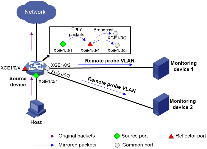
After you configure a remote probe VLAN (a concept in Layer 2 remote port mirroring) for a local mirroring group, mirrored packets are broadcast within the remote probe VLAN. To configure local port mirroring with multiple monitor ports by remote probe VLAN:
1. Configure a remote source group on the local device.
2. Configure mirroring sources, a remote probe VLAN, and a reflector port for the remote source group.
3. Assign the ports connecting to the data monitoring devices to the remote probe VLAN.
Then, mirrored packets are broadcast in the remote probe VLAN and sent out the member ports of the remote probe VLAN to the data monitoring devices.
This feature is supported on all devices that support Layer 2 remote port mirroring in reflector port mode.
Figure 2 Local port mirroring with multiple monitor ports through remote probe VLAN
Example: Configuring local port mirroring with multiple monitor ports through remote probe VLAN
# Create remote source group 1.
<Device> system-view
[Device] mirroring-group 1 remote-source
# Configure Ten-GigabitEthernet 1/0/1 as the source port of remote source group 1.
[Device] mirroring-group 1 mirroring-port ten-gigabitethernet 1/0/3 both
# Configure an unused port (Ten-GigabitEthernet 1/0/4 in this example) as the reflector port of remote source group 1.
[Device] mirroring-group 1 reflector-port ten-gigabitethernet 1/0/4
This operation may delete all settings made on the interface. Continue? [Y/N]: y
# Create VLAN 10, which is to be used as the remote probe VLAN. Assign the ports connecting to the data monitoring devices to VLAN 10.
[Device] vlan 10
[Device-vlan10] port ten-gigabitethernet 1/0/2 to ten-gigabitethernet 1/0/3
# Disable MAC address learning for VLAN 10 and configure VLAN 10 as the remote probe VLAN.
[Device-vlan10] undo mac-address mac-learning enable
[Device-vlan10] quit
[Device] mirroring-group 1 remote-probe vlan 10
Layer 2 remote port mirroring (RSPAN)
In Layer 2 remote mirroring, the mirroring sources and mirroring destinations are assigned to different mirroring groups on different devices. Layer 2 remote port mirroring involves the following concepts:
· Remote source group—Mirroring group containing mirroring sources.
· Remote destination group—Mirroring group containing mirroring destinations.
· Intermediate devices—Devices between the source device and destination device.
Layer 2 remote port mirroring can be implemented in reflector port mode or egress port mode.
RSPAN restrictions and guidelines
When configuring a reflector port, follow these restrictions and guidelines:
· The port to be configured as a reflector port must be a port not in use. Do not connect a network cable to a reflector port.
· When a port is configured as a reflector port, the default settings of the port are automatically restored. You cannot configure other features on the reflector port.
· A remote source group supports only one reflector port.
When configuring an egress port, a remote source group supports only one egress port.
When configuring a remote probe VLAN, follow these restrictions and guidelines:
· When a VLAN is configured as a remote probe VLAN, do not use the VLAN for any other purposes or create a VLAN interface for the VLAN. If you do this, duplicate mirrored packets will be sent to the CPUs.
· To prevent mirrored packets from being repeatedly forwarded between mirroring source ports and the remote probe VLAN, do not assign mirroring source ports to the remote probe VLAN. If you do this, the forwarding function of port mirroring and devices will be affected.
· If intermediate devices exist, for Layer 2 remote port mirroring to take effect, you must perform the following tasks:
¡ Permit the remote probe VLAN on the intermediate devices.
¡ Make sure the VLAN ID of packets is not modified or deleted on the intermediate devices.
· To mirror bidirectional packets of a port in a mirroring group, first disable MAC address learning for the remote probe VLAN on the source, intermediate, and destination devices.
· On a PVST-enabled device, you must disable PVST for the remote probe VLAN. Enabling PVST for the remote probe VLAN will affect STP calculation in the VLAN and affect traffic forwarding on ports in the VLAN.
For more restrictions and guidelines, see the configuration guides for the device.
RSPAN in reflector port mode
Introduction
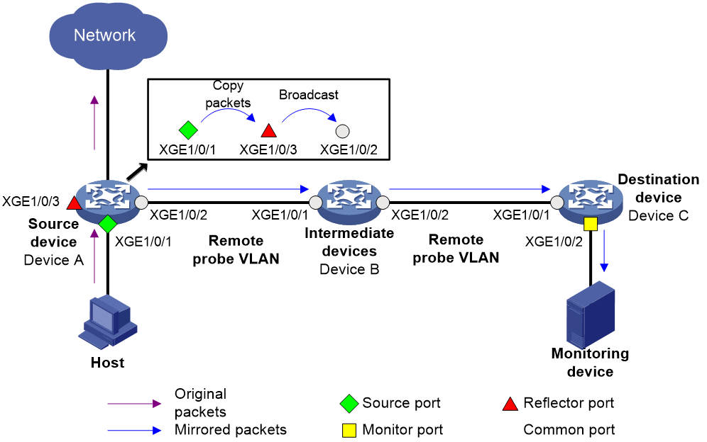
Figure 3 shows the process of implementing Layer 2 remote port mirroring in reflector port mode.
1. The source device copies packets entering the mirroring sources to the reflector port.
2. The reflector port broadcasts mirrored packets within the remote probe VLAN.
3. The intermediate devices send the mirrored packets to the destination device.
4. When receiving the mirrored packets, the destination device identifies whether the VLAN ID of the mirrored packets is the remote probe VLAN ID. If yes, the destination device forwards the packets to the data monitoring devices through the monitor ports.
Figure 3 Layer 2 remote port mirroring in reflector port mode
Example: Configuring RSPAN in reflector port mode
1. Configure Device C:
# Set the link type of Ten-GigabitEthernet 1/0/1 to trunk, and assign it to VLAN 2.
<DeviceC> system-view
[DeviceC] interface ten-gigabitethernet 1/0/1
[DeviceC-Ten-GigabitEthernet1/0/1] port link-type trunk
[DeviceC-Ten-GigabitEthernet1/0/1] port trunk permit vlan 2
[DeviceC-Ten-GigabitEthernet1/0/1] quit
# Create remote destination group 2.
[DeviceC] mirroring-group 2 remote-destination
# Create VLAN 2, which is to be used as the remote probe VLAN.
[DeviceC] vlan 2
# Disable MAC address learning for VLAN 2.
[DeviceC-vlan2] undo mac-address mac-learning enable
[DeviceC-vlan2] quit
# For remote destination group 2, configure VLAN 2 as the remote probe VLAN, and configure Ten-GigabitEthernet 1/0/2 as the monitor port. Disable the spanning tree protocol on Ten-GigabitEthernet 1/0/2 and assign it to VLAN 2.
[DeviceC] mirroring-group 2 remote-probe vlan 2
[DeviceC] interface ten-gigabitethernet 1/0/2
[DeviceC-Ten-GigabitEthernet1/0/2] mirroring-group 2 monitor-port
[DeviceC-Ten-GigabitEthernet1/0/2] undo stp enable
[DeviceC-Ten-GigabitEthernet1/0/2] port access vlan 2
[DeviceC-Ten-GigabitEthernet1/0/2] quit
2. Configure Device B:
# Create VLAN 2, which is to be used as the remote probe VLAN.
<DeviceB> system-view
[DeviceB] vlan 2
# Disable MAC address learning for VLAN 2.
[DeviceB-vlan2] undo mac-address mac-learning enable
[DeviceB-vlan2] quit
# Set the link type of Ten-GigabitEthernet 1/0/1 to trunk, and assign it to VLAN 2.
[DeviceB] interface ten-gigabitethernet 1/0/1
[DeviceB-Ten-GigabitEthernet1/0/1] port link-type trunk
[DeviceB-Ten-GigabitEthernet1/0/1] port trunk permit vlan 2
[DeviceB-Ten-GigabitEthernet1/0/1] quit
# Set the link type of Ten-GigabitEthernet 1/0/2 to trunk, and assign it to VLAN 2.
[DeviceB] interface ten-gigabitethernet 1/0/2
[DeviceB-Ten-GigabitEthernet1/0/2] port link-type trunk
[DeviceB-Ten-GigabitEthernet1/0/2] port trunk permit vlan 2
[DeviceB-Ten-GigabitEthernet1/0/2] quit
3. Configure Device A:
# Create remote source group 1.
<DeviceA> system-view
[DeviceA] mirroring-group 1 remote-source
# Create VLAN 2, which is to be used as the remote probe VLAN.
[DeviceA] vlan 2
# Disable MAC address learning for VLAN 2.
[DeviceA-vlan2] undo mac-address mac-learning enable
[DeviceA-vlan2] quit
# For remote source group 1, configure VLAN 2 as the remote probe VLAN, Ten-GigabitEthernet 1/0/1 as the source port, and Ten-GigabitEthernet 1/0/3 as the reflector port.
[DeviceA] mirroring-group 1 remote-probe vlan 2
[DeviceA] mirroring-group 1 mirroring-port ten-gigabitethernet 1/0/1 both
[DeviceA] mirroring-group 1 reflector-port ten-gigabitethernet 1/0/3
This operation may delete all settings made on the interface. Continue? [Y/N]: y
# Set the link type of Ten-GigabitEthernet 1/0/2 to trunk, and assign it to VLAN 2.
[DeviceA] interface ten-gigabitethernet 1/0/2
[DeviceA-Ten-GigabitEthernet1/0/2] port link-type trunk
[DeviceA-Ten-GigabitEthernet1/0/2] port trunk permit vlan 2
[DeviceA-Ten-GigabitEthernet1/0/2] quit
4. Verify the configuration:
# Display configuration information of all mirroring groups on Device C.
[DeviceC] display mirroring-group all
Mirroring group 2:
Type: Remote destination
Status: Active
Monitor port: Ten-GigabitEthernet1/0/2
Remote probe VLAN: 2
# Display configuration information of all mirroring groups on Device A.
[DeviceA] display mirroring-group all
Mirroring group 1:
Type: Remote source
Status: Active
Mirroring port:
Ten-GigabitEthernet1/0/1 Both
Reflector port: Ten-GigabitEthernet1/0/3
Remote probe VLAN: 2
RSPAN in egress port mode
Introduction
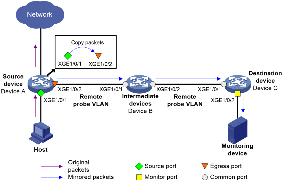
Figure 4 shows the process of implementing Layer 2 remote port mirroring in egress port mode.
1. The source device copies packets entering the mirroring sources to the egress port.
2. The egress port forwards the mirrored packets to intermediate devices.
3. The intermediate devices broadcast mirrored packets in the remote probe VLAN to the destination device.
4. When receiving the mirrored packets, the destination device identifies whether the VLAN ID of the mirrored packets is the remote probe VLAN ID. If yes, the destination device forwards the packets to the data monitoring devices through the monitor ports.
Figure 4 Layer 2 remote port mirroring in egress port mode
Example: Configuring RSPAN in egress port mode
1. Configure Device C:
# Set the link type of Ten-GigabitEthernet 1/0/1 to trunk, and assign it to VLAN 2.
<DeviceC> system-view
[DeviceC] interface ten-gigabitethernet 1/0/1
[DeviceC-Ten-GigabitEthernet1/0/1] port link-type trunk
[DeviceC-Ten-GigabitEthernet1/0/1] port trunk permit vlan 2
[DeviceC-Ten-GigabitEthernet1/0/1] quit
# Create remote destination group 2.
[DeviceC] mirroring-group 2 remote-destination
# Create VLAN 2, which is to be used as the remote probe VLAN.
[DeviceC] vlan 2
# Disable MAC address learning for VLAN 2.
[DeviceC-vlan2] undo mac-address mac-learning enable
[DeviceC-vlan2] quit
# For remote destination group 2, configure VLAN 2 as the remote probe VLAN, and configure Ten-GigabitEthernet 1/0/2 as the monitor port. Disable the spanning tree protocol on Ten-GigabitEthernet 1/0/2 and assign it to VLAN 2.
[DeviceC] mirroring-group 2 remote-probe vlan 2
[DeviceC] interface ten-gigabitethernet 1/0/2
[DeviceC-Ten-GigabitEthernet1/0/2] mirroring-group 2 monitor-port
[DeviceC-Ten-GigabitEthernet1/0/2] undo stp enable
[DeviceC-Ten-GigabitEthernet1/0/2] port access vlan 2
[DeviceC-Ten-GigabitEthernet1/0/2] quit
2. Configure Device B:
# Create VLAN 2, which is to be used as the remote probe VLAN.
<DeviceB> system-view
[DeviceB] vlan 2
# Disable MAC address learning for VLAN 2.
[DeviceB-vlan2] undo mac-address mac-learning enable
[DeviceB-vlan2] quit
# Set the link type of Ten-GigabitEthernet 1/0/1 to trunk, and assign it to VLAN 2.
[DeviceB] interface ten-gigabitethernet 1/0/1
[DeviceB-Ten-GigabitEthernet1/0/1] port link-type trunk
[DeviceB-Ten-GigabitEthernet1/0/1] port trunk permit vlan 2
[DeviceB-Ten-GigabitEthernet1/0/1] quit
# Set the link type of Ten-GigabitEthernet 1/0/2 to trunk, and assign it to VLAN 2.
[DeviceB] interface ten-gigabitethernet 1/0/2
[DeviceB-Ten-GigabitEthernet1/0/2] port link-type trunk
[DeviceB-Ten-GigabitEthernet1/0/2] port trunk permit vlan 2
[DeviceB-Ten-GigabitEthernet1/0/2] quit
3. Configure Device A:
# Create remote source group 1.
<DeviceA> system-view
[DeviceA] mirroring-group 1 remote-source
# Create VLAN 2, which is to be used as the remote probe VLAN.
[DeviceA] vlan 2
# Disable MAC address learning for VLAN 2.
[DeviceA-vlan2] undo mac-address mac-learning enable
[DeviceA-vlan2] quit
# For remote source group 1, configure VLAN 2 as the remote probe VLAN, Ten-GigabitEthernet 1/0/1 as the source port, and Ten-GigabitEthernet 1/0/2 as the egress port.
[DeviceA] mirroring-group 1 remote-probe vlan 2
[DeviceA] mirroring-group 1 mirroring-port ten-gigabitethernet 1/0/1 both
[DeviceA] mirroring-group 1 monitor-egress ten-gigabitethernet 1/0/2
# Set the link type of Ten-GigabitEthernet 1/0/2 to trunk, assign it to VLAN 2, and disable the spanning tree protocol on it.
[DeviceA] interface ten-gigabitethernet 1/0/2
[DeviceA-Ten-GigabitEthernet1/0/2] port link-type trunk
[DeviceA-Ten-GigabitEthernet1/0/2] port trunk permit vlan 2
[DeviceA-Ten-GigabitEthernet1/0/2] undo stp enable
[DeviceA-Ten-GigabitEthernet1/0/2] quit
Layer 3 remote port mirroring (ERSPAN)
In Layer 3 remote port mirroring (ERSPAN), the source device and destination device are connected through a Layer 3 network.
ERSPAN encapsulates mirrored packets in GRE packets with protocol number 0x88BE and routes the packets to a remote monitoring device at Layer 3.
ERSPAN can be implemented in tunnel mode or encapsulation parameter mode.
ERSPAN in tunnel mode
Introduction
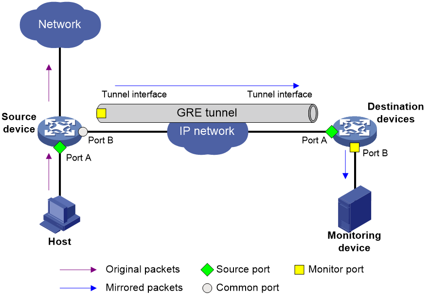
Layer 3 remote port mirroring in tunnel mode is implemented through local mirroring groups. To configure Layer 3 remote port mirroring in tunnel mode, configure a local mirroring group on the source device and destination device separately. For each local mirroring group, configure the mirroring sources and monitor ports. The differences between the two local mirroring groups are as follows:
· The local mirroring group on the source device is as follows:
¡ The source ports are ports to be monitored.
¡ The monitor port is the tunnel interface used for transmitting mirrored packets.
· The local mirroring group on the destination device is as follows:
¡ The source port is the physical interface of the tunnel interface.
¡ The monitor port is the port connecting to the data monitoring device.
Figure 5 shows the process of implementing Layer 3 remote port mirroring in tunnel mode.
1. The source device copies packets entering the source ports to the tunnel interface (the monitor port).
2. The packets are transmitted to the tunnel interface on the destination device through a GRE tunnel.
3. The destination device copies packets received on the physical interface of the tunnel interface (the source port) to the monitor port.
4. The monitor port on the destination device forwards the mirrored packets to the monitoring device.
When configuring ERSPAN in tunnel mode, follow these restrictions and guidelines:
· The mirrored packets sent to the monitoring device are ERSPAN-encapsulated. For the monitoring device to analyze the original packets, make sure the monitoring device supports decapsulating packets.
· Before configuring Layer 3 remote port mirroring in tunnel mode, first configure a GRE tunnel. If intermediate devices exist, configure a unicast routing protocol to ensure that the source device and the destination device can reach each other at Layer 3.
Figure 5 Layer 3 remote port mirroring in tunnel mode
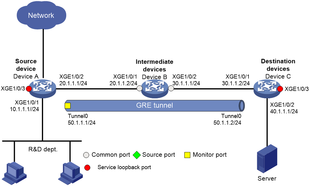
Example: Configuring ERSPAN in tunnel mode
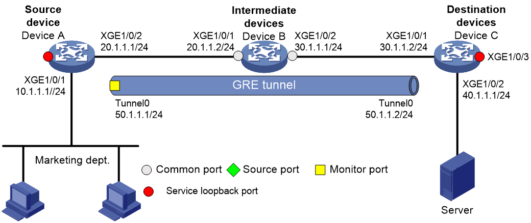
Network configuration
On a Layer 3 network, Device A, Device B, Device C, and Server are connected as shown in Figure 6. Device A is connected to the marketing department through Ten-GigabitEthernet 1/0/1.
Configure Layer 3 remote port mirroring and establish a GRE tunnel in OSPF mode. Then, the server can monitor all incoming packets and outgoing packets of the marketing department through mirrored packets transmitted in the GRE tunnel.
Procedure
1. Configure IP addresses and subnet masks for interfaces as shown in Figure 6. (Details not shown.)
2. Configure Device A:
# Create service loopback group 1, and specify tunnel services for the group.
<DeviceA> system-view
[DeviceA] service-loopback group 1 type tunnel
# Assign Ten-GigabitEthernet 1/0/3 to service loopback group 1.
[DeviceA] interface ten-gigabitethernet 1/0/3
[DeviceA-Ten-GigabitEthernet1/0/3] port service-loopback group 1
All configurations on the interface will be lost. Continue?[Y/N]:y
[DeviceA-Ten-GigabitEthernet1/0/3] quit
# Create GRE tunnel interface Tunnel 0. Assign an IP address and mask to the interface.
[DeviceA] interface tunnel 0 mode gre
[DeviceA-Tunnel0] ip address 50.1.1.1 24
# Specify a source IP address and destination IP address for interface Tunnel 0.
[DeviceA-Tunnel0] source 20.1.1.1
[DeviceA-Tunnel0] destination 30.1.1.2
[DeviceA-Tunnel0] quit
# Configure OSPF.
[DeviceA] ospf 1
[DeviceA-ospf-1] area 0
[DeviceA-ospf-1-area-0.0.0.0] network 10.1.1.0 0.0.0.255
[DeviceA-ospf-1-area-0.0.0.0] network 20.1.1.0 0.0.0.255
[DeviceA-ospf-1-area-0.0.0.0] quit
[DeviceA-ospf-1] quit
# Create local mirroring group 1.
[DeviceA] mirroring-group 1 local
# Configure Ten-GigabitEthernet 1/0/1 as a source port and interface Tunnel 0 as a monitor port for local mirroring group 1.
[DeviceA] mirroring-group 1 mirroring-port ten-gigabitethernet 1/0/1 both
[DeviceA] mirroring-group 1 monitor-port tunnel 0
3. Configure Device B:
# Configure OSPF.
<DeviceB> system-view
[DeviceB] ospf 1
[DeviceB-ospf-1] area 0
[DeviceB-ospf-1-area-0.0.0.0] network 20.1.1.0 0.0.0.255
[DeviceB-ospf-1-area-0.0.0.0] network 30.1.1.0 0.0.0.255
[DeviceB-ospf-1-area-0.0.0.0] quit
[DeviceB-ospf-1] quit
4. Configure Device C:
# Create service loopback group 1, and specify tunnel services for the group.
<DeviceC> system-view
[DeviceC] service-loopback group 1 type tunnel
# Assign Ten-GigabitEthernet 1/0/3 to service loopback group 1.
[DeviceC] interface ten-gigabitethernet 1/0/3
[DeviceC-Ten-GigabitEthernet1/0/3] port service-loopback group 1
All configurations on the interface will be lost. Continue?[Y/N]:y
[DeviceC-Ten-GigabitEthernet1/0/3] quit
# Create GRE tunnel interface Tunnel 0. Assign an IP address and mask to the interface.
[DeviceC] interface tunnel 0 mode gre
[DeviceC-Tunnel0] ip address 50.1.1.2 24
# Specify a source IP address and destination IP address for interface Tunnel 0.
[DeviceC-Tunnel0] source 30.1.1.2
[DeviceC-Tunnel0] destination 20.1.1.1
[DeviceC-Tunnel0] quit
# Configure OSPF.
[DeviceC] ospf 1
[DeviceC-ospf-1] area 0
[DeviceC-ospf-1-area-0.0.0.0] network 30.1.1.0 0.0.0.255
[DeviceC-ospf-1-area-0.0.0.0] network 40.1.1.0 0.0.0.255
[DeviceC-ospf-1-area-0.0.0.0] quit
[DeviceC-ospf-1] quit
# Create local mirroring group 1.
[DeviceC] mirroring-group 1 local
# Configure Ten-GigabitEthernet 1/0/1 as a source port and Ten-GigabitEthernet 1/0/2 as a monitor port for local mirroring group 1.
[DeviceC] mirroring-group 1 mirroring-port ten-gigabitethernet 1/0/1 inbound
[DeviceC] mirroring-group 1 monitor-port ten-gigabitethernet 1/0/2
Verifying the configuration
# Display configuration information of all mirroring groups on Device A.
[DeviceA] display mirroring-group all
Mirroring group 1:
Type: Local
Status: Active
Mirroring port:
Ten-GigabitEthernet1/0/1 Both
Monitor port: Tunnel0
# Display configuration information of all mirroring groups on Device C.
[DeviceC] display mirroring-group all
Mirroring group 1:
Type: Local
Status: Active
Mirroring port:
Ten-GigabitEthernet1/0/1 Inbound
Monitor port: Ten-GigabitEthernet1/0/2
Verify that you can monitor the incoming packets and outgoing packets of the marketing department on the server.
ERSPAN in encapsulation parameter mode
Introduction
Configure Layer 3 remote port mirroring in encapsulation parameter mode only on the source device. Additionally, configure unicast routing protocols on all devices to ensure that devices can communicate at Layer 3.
To configure ERSPAN in encapsulation parameter mode:
1. Create a local mirroring group on the source device.
2. Specify the source ports and monitor ports for the local mirroring group.
When configuring a monitor port, specify the monitoring device IP as the destination IP and the monitor port IP as the source IP for mirrored packets.
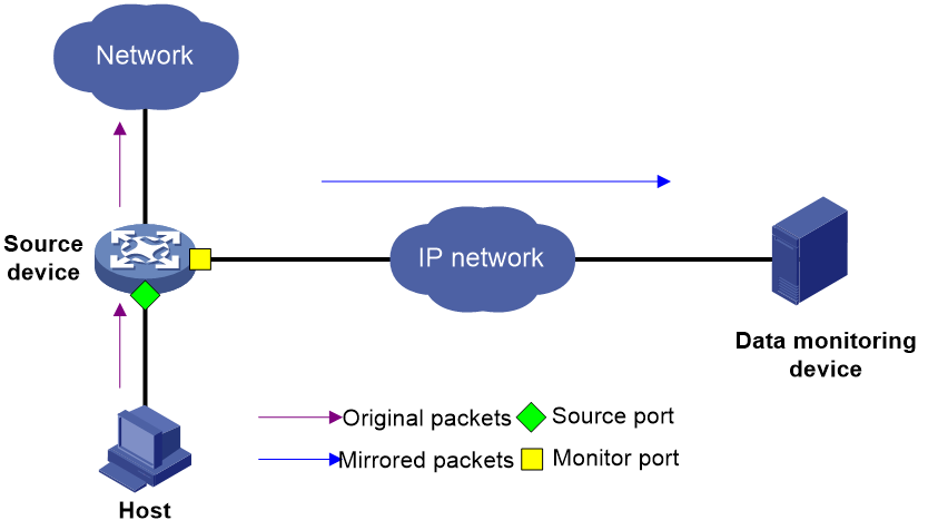
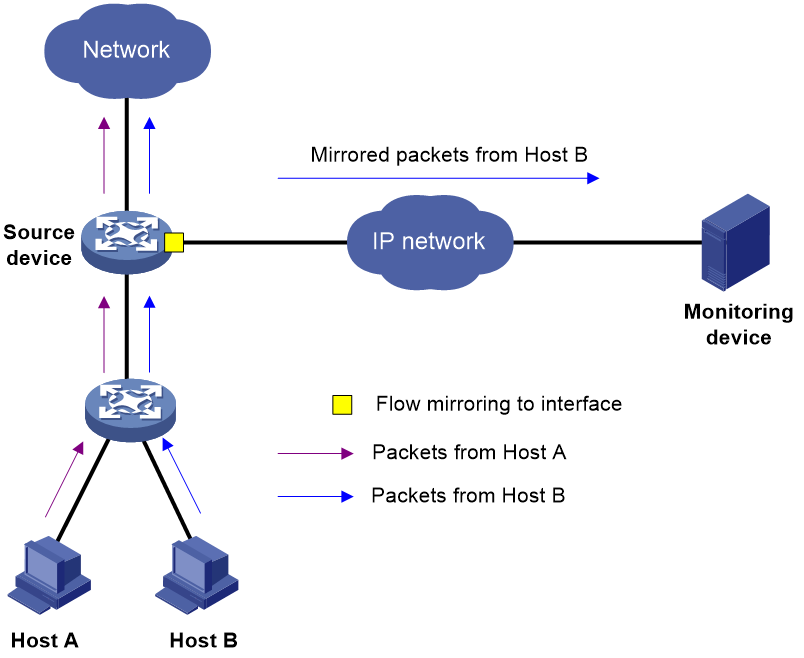
As shown in Figure 7, ERSPAN in encapsulation parameter mode forwards packets as follows:
1. The source device copies a packet passing through a source port.
2. The source device encapsulates the packet with the specified encapsulation parameters (monitoring device IP as destination IP and monitor port IP as source IP).
3. The encapsulated packet is routed to the monitoring device.
4. The monitoring device decapsulates the packet and analyzes the packet contents.
The packet sent to the monitoring device through ERSPAN in encapsulation parameter mode is encapsulated. In this mode, make sure the monitoring device supports decapsulating the packet.
Figure 7 Layer 3 remote port mirroring in encapsulation parameter mode
Example: Configuring ERSPAN in encapsulation parameter mode
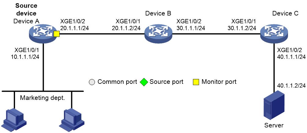
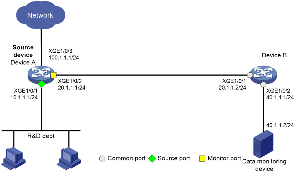
Network configuration
On a Layer 3 network, Device A, Device B, Device C, and Server are connected as shown in Figure 8. Device A is connected to the marketing department through Ten-GigabitEthernet 1/0/1.
Configure Layer 3 remote port mirroring to enable the server to monitor all incoming packets and outgoing packets of the marketing department through mirrored packets from Device C.
Procedure
1. Configure IP addresses and subnet masks for interfaces as shown in Figure 8. (Details not shown.)
2. Configure Device A:
# Configure OSPF.
[DeviceA] ospf 1
[DeviceA-ospf-1] area 0
[DeviceA-ospf-1-area-0.0.0.0] network 10.1.1.0 0.0.0.255
[DeviceA-ospf-1-area-0.0.0.0] network 20.1.1.0 0.0.0.255
[DeviceA-ospf-1-area-0.0.0.0] quit
[DeviceA-ospf-1] quit
# Create local mirroring group 1.
[DeviceA] mirroring-group 1 local
# Configure Ten-GigabitEthernet 1/0/1 as a source port and Ten-GigabitEthernet 1/0/2 as a monitor port for local mirroring group 1. Encapsulate the mirrored packets with destination IP address 40.1.1.2 and source IP address 20.1.1.1.
[DeviceA] mirroring-group 1 mirroring-port ten-gigabitethernet 1/0/1 both
[DeviceA] mirroring-group 1 monitor-port ten-gigabitethernet 1/0/2 destination-ip 40.1.1.2 source-ip 20.1.1.1
3. Configure Device B:
# Configure OSPF.
<DeviceB> system-view
[DeviceB] ospf 1
[DeviceB-ospf-1] area 0
[DeviceB-ospf-1-area-0.0.0.0] network 20.1.1.0 0.0.0.255
[DeviceB-ospf-1-area-0.0.0.0] network 30.1.1.0 0.0.0.255
[DeviceB-ospf-1-area-0.0.0.0] quit
[DeviceB-ospf-1] quit
4. Configure Device C:
# Configure OSPF.
[DeviceC] ospf 1
[DeviceC-ospf-1] area 0
[DeviceC-ospf-1-area-0.0.0.0] network 30.1.1.0 0.0.0.255
[DeviceC-ospf-1-area-0.0.0.0] network 40.1.1.0 0.0.0.255
[DeviceC-ospf-1-area-0.0.0.0] quit
[DeviceC-ospf-1] quit
Verifying the configuration
# Display configuration information of all mirroring groups on Device A.
[DeviceA] display mirroring-group all
Mirroring group 1:
Type: Local
Status: Active
Mirroring port:
Ten-GigabitEthernet1/0/1 Both
Monitor port: Ten-GigabitEthernet1/0/2
Encapsulation: Destination IP address 40.1.1.2
Source IP address 20.1.1.1
Destination MAC address 000f-e241-5e5b
Verify that you can monitor the incoming packets and outgoing packets of the marketing department on the server.
Hardware and port mirroring compatibility matrix
|
Hardware (right) |
S6800 S6860 S6861 S6820 |
S6805 S6850 S9850 S9820-64H |
S9820-8C |
S12500-X S12500X-AF |
S12500R S12500CR |
|
Item (below) |
|||||
|
Max number of mirroring groups |
4 |
15 |
15 |
||
|
Source port types (directions) |
Layer 2 or Layer 3 Ethernet interfaces (inbound and outbound) |
· Layer 2 or Layer 3 Ethernet interfaces (inbound and outbound) · Layer 2 or Layer 3 aggregate interfaces (inbound and outbound) |
· Layer 2 or Layer 3 Ethernet interfaces (inbound and outbound) · Layer 2 or Layer 3 aggregate interfaces (inbound and outbound) |
Layer 2 or Layer 3 Ethernet interfaces (inbound and outbound) |
Layer 2 or Layer 3 Ethernet interfaces (inbound and outbound) |
|
Max number of source CPUs (directions) |
Multiple (inbound) |
Multiple (inbound) |
One (inbound) |
Multiple (inbound) |
Multiple (inbound) |
|
Packet sampling |
No |
No |
No |
Yes in local mirroring groups |
Yes in local mirroring groups |
|
Monitor port types |
· Layer 2 or Layer 3 Ethernet interfaces · Layer 2 aggregate interfaces |
· Layer 2 or Layer 3 Ethernet interfaces · Layer 2 aggregate interfaces |
Layer 2 or Layer 3 Ethernet interfaces |
· Layer 2 or Layer 3 Ethernet interfaces · Layer 2 aggregate interfaces |
· Layer 2 or Layer 3 Ethernet interfaces · Layer 2 aggregate interfaces |
|
Max number of source ports in a mirroring group |
Not limited |
||||
|
Max number of monitor ports in a mirroring group |
One |
· Local mirroring group: Multiple · Remote destination group: One |
· Local mirroring group: Multiple · Remote destination group: One |
||
|
Max number of mirroring groups to which a source port can be assigned |
· Four as unidirectional source ports · Two as bidirectional source ports · Three (one as bidirectional source port + two as unidirectional source ports) |
One |
One |
||
|
Max number of mirroring groups to which a monitor port can be assigned |
One |
||||
|
Mirroring cross IRF member devices or cards |
Supported |
N/A |
Mirroring cross IRF member devices: · Type H cards: Supported · Type F cards: Not supported Cross-card mirroring: Supported |
· Cross-card mirroring: Supported · Mirroring cross IRF member devices: N/A |
|
|
Layer 2 remote port mirroring in reflector port mode |
Supported |
||||
|
Layer 2 remote port mirroring in egress port mode |
Supported |
||||
|
Layer 3 remote port mirroring in tunnel mode |
Supported |
||||
|
Layer 3 remote port mirroring in encapsulation parameter mode |
Supported |
Not supported |
Not supported |
||
Flow mirroring
Introduction
Flow mirroring is implemented through QoS. It copies packets matching a traffic class to a destination for packet analysis and monitoring. By flow mirroring, you can flexibly configure packet match criteria to granularly identify packets and send matching packets to the specified destination.
Similar to port mirroring, flow mirroring to interfaces includes the following types depending on whether the mirroring sources and mirroring destinations are on the same device:
· Flow mirroring SPAN—Mirrors traffic to local interfaces.
· Flow mirroring ERSPAN—Encapsulates traffic in GRE packets with protocol number 0x88BE and routes the packets to Layer 3 remote monitoring devices.
Flow mirroring to local interfaces (SPAN)
Introduction
To configure flow mirroring SPAN, configure a QoS policy on the source device. In the QoS policy, configure a traffic class to match packets and configure a traffic behavior to mirror packets to a local interface without specifying the loopback keyword or encapsulation parameters.
When the source device receives a matching packet, the device sends one copy of the packet to the interface specified by the traffic behavior. The interface forwards the packet to the monitoring device.
On the S12500-X/S12500X-AF/S12500R/S12500CR switch series, you can also flow-mirror traffic to local interfaces through a monitoring group. To do that, assign a single port (which can be an aggregate interface) or multiple ports to a monitoring group, and configure a traffic behavior to mirror traffic to the monitoring group. When the monitoring group receives a matching packet, the monitoring group copies the packet to each member port. Then, each member port directly forwards the packet to the connected monitoring device.
Example: Flow-mirroring traffic to local interfaces in interface mode
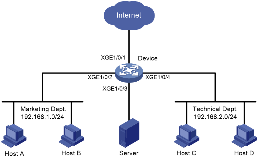
Network configuration
In the company, the departments use IP addresses on different subnets. The marketing department uses the 192.168.1.0/24 subnet, and the technical department uses the 192.168.2.0/24 subnet. The working hours of the company are 8:00 to 18:00 on each working day.
Configure flow mirroring to meet the following requirements:
· Enable the server to monitor the Internet accessing traffic with port 80 from the technical department.
· Enable the server to monitor the IP traffic from the technical department to the marketing department during the working hours.
Figure 9 Network diagram
Procedure
# Create a time range named work. Configure it to be active between 8:00 to 18:00 during working days.
<Device> system-view
[Device] time-range work 8:00 to 18:00 working-day
# Create advanced IPv4 ACL 3000. Configure a rule to match the Internet accessing traffic with port 80 from the technical department. Configure another rule to match the IP packets from the technical department to the marketing department during the working hours.
[Device] acl advanced 3000
[Device-acl-ipv4-adv-3000] rule permit tcp source 192.168.2.0 0.0.0.255 destination-port eq www
[Device-acl-ipv4-adv-3000] rule permit ip source 192.168.2.0 0.0.0.255 destination 192.168.1.0 0.0.0.255 time-range work
[Device-acl-ipv4-adv-3000] quit
# Create traffic class tech_c, and use ACL 3000 as a match criterion.
[Device] traffic classifier tech_c
[Device-classifier-tech_c] if-match acl 3000
[Device-classifier-tech_c] quit
# Create traffic behavior tech_b, and configure an action of mirroring traffic to interface Ten-GigabitEthernet 1/0/3.
[Device] traffic behavior tech_b
[Device-behavior-tech_b] mirror-to interface ten-gigabitethernet 1/0/3
[Device-behavior-tech_b] quit
# Create QoS policy tech_p, and associate traffic class tech_c with traffic behavior tech_b.
[Device] qos policy tech_p
[Device-qospolicy-tech_p] classifier tech_c behavior tech_b
[Device-qospolicy-tech_p] quit
# Apply QoS policy tech_p to the inbound direction of Ten-GigabitEthernet 1/0/4.
[Device] interface ten-gigabitethernet 1/0/4
[Device-Ten-GigabitEthernet1/0/4] qos apply policy tech_p inbound
[Device-Ten-GigabitEthernet1/0/4] quit
Verifying the configuration
Verify that the following requirements are met:
· The server can monitor the Internet accessing traffic with port 80 from the technical department.
· The server can monitor the IP traffic from the technical department to the marketing department during the working hours.
Example: Flow-mirroring traffic to local interfaces in monitoring group mode
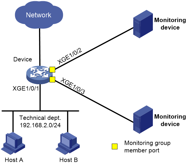
Network configuration
The technical department of a company uses the 192.168.2.0/24 subnet. Configure flow mirroring to mirror traffic to a monitoring group. Then, each monitoring device can monitor the Internet accessing traffic with port 80 from the technical department.
Figure 10 Network diagram
Restrictions and guidelines
Only the S12500-X/S12500X-AF/S12500R/S12500CR switch series support flow-mirroring traffic to monitoring groups.
Procedure
# Create advanced IPv4 ACL 3000. Configure a rule to match the Internet accessing traffic with port 80 from the technical department.
[Device] acl advanced 3000
[Device-acl-ipv4-adv-3000] rule permit tcp source 192.168.2.0 0.0.0.255 destination-port eq www
[Device-acl-ipv4-adv-3000] quit
# Create monitoring group 1, and assign interfaces Ten-GigabitEthernet 1/0/2 and Ten-GigabitEthernet 1/0/3 to the monitoring group.
<Device> system-view
[Device] monitoring-group 1
[Device-monitoring-group-1] monitoring-port ten-gigabitethernet 1/0/2 to ten-gigabitethernet 1/0/3
# Create traffic class tech_c, and use ACL 3000 as a match criterion.
[Device] traffic classifier tech_c
[Device-classifier-tech_c] if-match acl 3000
[Device-classifier-tech_c] quit
# Create traffic behavior tech_b, and configure an action of mirroring traffic to monitoring group 1.
[Device] traffic behavior tech_b
[Device-behavior-tech_b] mirror-to monitoring-group 1
[Device-behavior-tech_b] quit
# Create QoS policy tech_p, and associate traffic class tech_c with traffic behavior tech_b.
[Device] qos policy tech_p
[Device-qospolicy-tech_p] classifier tech_c behavior tech_b
[Device-qospolicy-tech_p] quit
# Apply QoS policy tech_p to the inbound direction of interface Ten-GigabitEthernet 1/0/1.
[Device] interface ten-gigabitethernet 1/0/1
[Device-Ten-GigabitEthernet1/0/1] qos apply policy tech_p inbound
[Device-Ten-GigabitEthernet1/0/1] quit
Verifying the configuration
Verify that each monitoring device can monitor the Internet accessing traffic with port 80 from the technical department.
Flow-mirroring to Layer 3 remote devices (ERSPAN)
Flow mirroring ERSPAN modes
Flow mirroring ERSPAN is implemented in one of the following modes:
· Interface mode—Flow-mirrors traffic to interfaces. Flow mirroring ERSPAN in this mode can be implemented in one of the following methods:
¡ Specifying the loopback parameter.
¡ Configuring encapsulation parameters.
· Monitoring group mode—Flow-mirrors traffic to monitoring groups. Flow mirroring ERSPAN in this mode can be implemented in one of the following methods:
¡ Specifying encapsulation parameters for monitoring group members.
¡ Specifying tunnel interfaces as the monitoring group members.
Restrictions and guidelines
To flow-mirror traffic to Layer 3 remote devices, you must configure unicast routing protocols on all devices to ensure that devices can communicate at Layer 3.
The S12500-X/S12500X-AF/S12500R/S12500CR switch series does not support flow mirroring ERSPAN in interface mode.
Only the S12500-X/S12500X-AF/S12500R/S12500CR switch series supports flow mirroring ERSPAN in monitoring group mode.
For more flow mirroring compatibility, see “Hardware and flow mirroring compatibility matrix.”
Flow mirroring ERSPAN in interface mode and configuration examples
Flow mirroring to interfaces in loopback mode
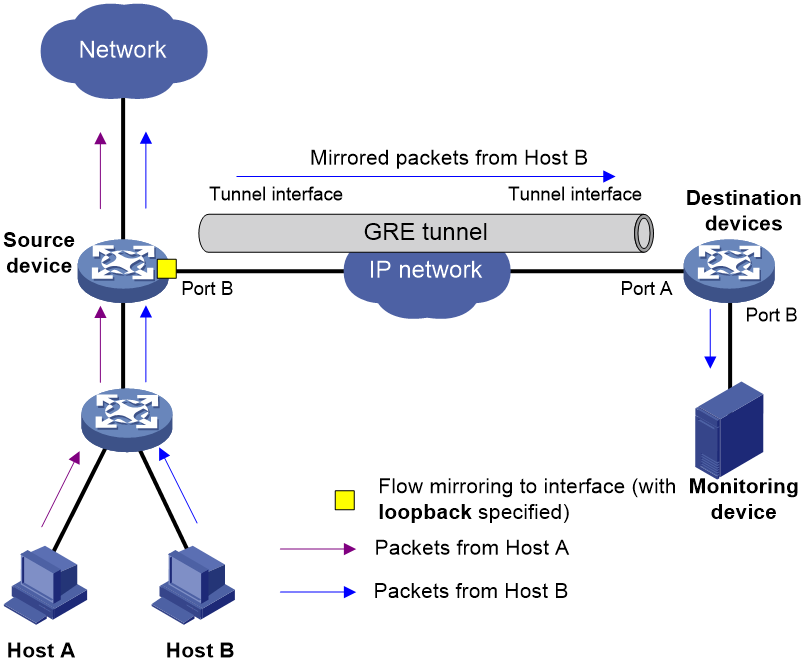
Introduction
As shown in Figure 11, configure flow mirroring to interfaces in loopback mode as follows:
1. Configure a QoS policy on the source device, and apply the QoS policy to the source interfaces. In the QoS policy, configure a traffic class to match packets, and configure a traffic behavior to mirror packets to Port B and specify the loopback keyword.
2. Configure a QoS policy on the source device and apply the QoS policy to Port B. In the QoS policy, configure a traffic class to match packets, and configure a traffic behavior to redirect packets to a tunnel interface.
The destination device receives mirrored packets on the tunnel interface and decapsulates the packets. Then, the device forwards the packets based on the destination IP address of the original packets. Make sure the device has the route and ARP entry to the destination IP address.
Figure 11 Flow mirroring to interfaces in loopback mode
Example: Flow-mirroring traffic to interfaces in loopback mode
Network configuration
As shown in Figure 12, the R&D department of a company uses the 10.1.1.1/24 subnet. Configure remote flow mirroring to enable the monitoring device to monitor the HTTP traffic from the R&D department for accessing destination IP address 100.1.1.1 on Internet.
Procedure
1. Configure Device A:
# Assign IP address 20.1.1.1 to interface Ten-GigabitEthernet 1/0/2.
<DeviceA> system-view
[DeviceA] interface ten-gigabitethernet 1/0/2
[DeviceA-Ten-GigabitEthernet1/0/2] port link-mode route
[DeviceA-Ten-GigabitEthernet1/0/2] ip address 20.1.1.1 24
[DeviceA-Ten-GigabitEthernet1/0/2] quit
# Assign IP addresses to other interfaces in the same way. (Details not shown.)
# Create service loopback group 1, and specify tunnel services for the group.
[DeviceA] service-loopback group 1 type tunnel
# Assign interface Ten-GigabitEthernet 1/0/3 to service loopback group 1.
[DeviceA] interface ten-gigabitethernet 1/0/3
[DeviceA-Ten-GigabitEthernet1/0/3] port service-loopback group 1
All configurations on the interface will be lost. Continue?[Y/N]:y
[DeviceA-Ten-GigabitEthernet1/0/3] quit
# Create GRE tunnel interface Tunnel 0. Assign an IP address and mask to the interface.
[DeviceA] interface tunnel 0 mode gre
[DeviceA-Tunnel0] ip address 50.1.1.1 24
# Specify a source IP address and destination IP address for interface Tunnel 0.
[DeviceA-Tunnel0] source 20.1.1.1
[DeviceA-Tunnel0] destination 30.1.1.2
[DeviceA-Tunnel0] quit
# Configure OSPF.
[DeviceA] ospf 1
[DeviceA-ospf-1] area 0
[DeviceA-ospf-1-area-0.0.0.0] network 10.1.1.0 0.0.0.255
[DeviceA-ospf-1-area-0.0.0.0] network 20.1.1.0 0.0.0.255
[DeviceA-ospf-1-area-0.0.0.0] network 100.1.1.0 0.0.0.255
[DeviceA-ospf-1-area-0.0.0.0] quit
[DeviceA-ospf-1] quit
# Create ACL 3000, and configure a rule to match the Internet accessing traffic of the R&D department.
[DeviceA] acl number 3000
[DeviceA-acl-adv-3000] rule permit tcp destination-port eq 80 source 10.1.1.0 0.0.0.255
[DeviceA-acl-adv-3000] quit
# Create traffic class classifier_research, and use ACL 3000 as a match criterion.
[DeviceA] traffic classifier classifier_research
[DeviceA-classifier-classifier_research] if-match acl 3000
[DeviceA-classifier-classifier_research] quit
# Create traffic behavior behavior_research. Configure an action of mirroring traffic to interface Ten-GigabitEthernet 1/0/3. Specify the loopback keyword, so the mirrored packets are forwarded to the destination device through a GRE tunnel.
[DeviceA] traffic behavior behavior_research
[DeviceA-behavior-behavior_research] mirror-to interface ten-gigabitethernet 1/0/3 loopback
[DeviceA-behavior-behavior_research] quit
# Create QoS policy policy_research. Associate traffic class classifier_research with traffic behavior behavior_research.
[DeviceA] qos policy policy_research
[DeviceA-qospolicy-policy_research] classifier classifier_research behavior behavior_research
[DeviceA-qospolicy-policy_research] quit
# Apply QoS policy policy_research to the inbound direction of interface Ten-GigabitEthernet 1/0/1.
[DeviceA] interface Ten-GigabitEthernet 1/0/1
[DeviceA-Ten-GigabitEthernet1/0/1] qos apply policy policy_research inbound
[DeviceA-Ten-GigabitEthernet1/0/1] quit
# Create traffic class classifier_redirect, and configure it to match any traffic.
[DeviceA] traffic classifier classifier_redirect
[DeviceA-classifier-classifier_redirect] if-match any
[DeviceA-classifier-classifier_redirect] quit
# Create traffic behavior behavior_redirect, and configure an action of redirecting traffic to interface Tunnel 0.
[DeviceA] traffic behavior behavior_redirect
[DeviceA-behavior-behavior_redirect] redirect interface Tunnel0
[DeviceA-behavior-behavior_redirect] quit
# Create QoS policy policy_redirect. Associate traffic class classifier_redirect with traffic behavior behavior_redirect.
[DeviceA] qos policy policy_redirect
[DeviceA-qospolicy-policy_redirect] classifier classifier_redirect behavior behavior_redirect
[DeviceA-qospolicy-policy_redirect] quit
# Apply QoS policy policy_redirect to the inbound direction of interface Ten-GigabitEthernet 1/0/3.
[DeviceA] interface Ten-GigabitEthernet 1/0/3
[DeviceA-Ten-GigabitEthernet1/0/3] qos apply policy policy_redirect inbound
[DeviceA-Ten-GigabitEthernet1/0/3] quit
2. Configure Device B:
# Configure OSPF.
<DeviceB> system-view
[DeviceB] ospf 1
[DeviceB-ospf-1] area 0
[DeviceB-ospf-1-area-0.0.0.0] network 20.1.1.0 0.0.0.255
[DeviceB-ospf-1-area-0.0.0.0] network 30.1.1.0 0.0.0.255
[DeviceB-ospf-1-area-0.0.0.0] quit
[DeviceB-ospf-1] quit
3. Configure Device C:
# Create service loopback group 1, and specify tunnel services for the group.
<DeviceC> system-view
[DeviceC] service-loopback group 1 type tunnel
# Assign interface Ten-GigabitEthernet 1/0/3 to service loopback group 1.
[DeviceC] interface ten-gigabitethernet 1/0/3
[DeviceC-Ten-GigabitEthernet1/0/3] port service-loopback group 1
All configurations on the interface will be lost. Continue?[Y/N]:y
[DeviceC-Ten-GigabitEthernet1/0/3] quit
# Create GRE tunnel interface Tunnel 0. Assign an IP address and mask to the interface.
[DeviceC] interface tunnel 0 mode gre
[DeviceC-Tunnel0] ip address 50.1.1.2 24
# Specify a source IP address and destination IP address for interface Tunnel 0.
[DeviceC-Tunnel0] source 30.1.1.2
[DeviceC-Tunnel0] destination 20.1.1.1
[DeviceC-Tunnel0] quit
# Configure OSPF.
[DeviceC] ospf 1
[DeviceC-ospf-1] area 0
[DeviceC-ospf-1-area-0.0.0.0] network 30.1.1.0 0.0.0.255
[DeviceC-ospf-1-area-0.0.0.0] network 40.1.1.0 0.0.0.255
[DeviceC-ospf-1-area-0.0.0.0] quit
[DeviceC-ospf-1] quit
# Configure a static ARP entry on Device C to specify the MAC address for IP address 100.1.1.1 as 00e0-fc58-1238, the MAC address of interface Ten-GigabitEthernet 1/0/2. When Device C receives a packet with destination IP address 100.1.1.1, the packet is directly forwarded to interface Ten-GigabitEthernet 1/0/2.
[DeviceC] arp static 100.1.1.1 00e0-fc58-1238
Verifying the configuration
# Display the flow mirroring configuration information on Device A.
[DeviceA] display qos policy interface
Interface: Ten-GigabitEthernet1/0/1
Direction: Inbound
Policy: policy_research
Classifier: classifier_research
Operator: AND
Rule(s) :
If-match acl 3000
Behavior: behavior_research
Mirroring:
Mirror to the interface: Ten-GigabitEthernet1/0/3
Interface: Ten-GigabitEthernet1/0/3
Direction: Inbound
Policy: policy_redirect
Classifier: classifier_redirect
Operator: AND
Rule(s) :
If-match any
Behavior: behavior_redirect
Redirecting:
Redirect to interface Tunnel0
Flow mirroring to interfaces in encapsulation parameter mode
Introduction
To configure flow mirroring to interfaces in encapsulation parameter mode, configure a QoS policy on the source device. In the QoS policy, configure a traffic class to match packets, and configure a traffic behavior to mirror traffic to an interface and specify the encapsulation parameters.
You can configure flow mirroring to interfaces in encapsulation parameter mode in one of the following methods:
· Directly specifying an outgoing interface—In this method, specify both the outgoing interface and encapsulation parameters. The device encapsulates packets with the specified parameters and then forwards packets out the specified outgoing interface.
· Specifying outgoing interfaces through route lookup—In this method, specify only encapsulation parameters without specifying an outgoing interface. The device looks up a route for the encapsulated mirrored packets based on their source IP address and destination IP address. The outgoing interface of the route is the destination interface of the mirrored packets.
In this method, you can use the load sharing function of a routing protocol to mirror packets to multiple destination interfaces.
As shown in Figure 13, flow mirroring to interfaces in encapsulation parameter mode works as follows:
1. The source device copies a matching packet.
2. The source device encapsulates the packet with the specified ERSPAN encapsulation parameters. Then, the device forwards the packet out the specified outgoing interface or looks up a route for the mirrored packet based on its source IP and destination IP.
3. The encapsulated packet is routed to the monitoring device.
4. The monitoring device decapsulates the packet and analyzes the packet contents.
The packet sent to the monitoring device through ERSPAN in encapsulation parameter mode is encapsulated. In this mode, make sure the monitoring device supports decapsulating the packet.
Figure 13 Flow mirroring to interfaces in encapsulation parameter mode
Example: Flow-mirroring traffic to interfaces in encapsulation parameter mode
Network configuration
As shown in Figure 14, the R&D department of a company uses the 10.1.1.1/24 subnet. Configure remote flow mirroring to enable the monitoring device to monitor the HTTP traffic from the R&D department for accessing destination IP address 100.1.1.1 on Internet.
Procedure
1. Configure Device A:
# Assign IP address 20.1.1.1 to interface Ten-GigabitEthernet 1/0/2.
<DeviceA> system-view
[DeviceA] interface ten-gigabitethernet 1/0/2
[DeviceA-Ten-GigabitEthernet1/0/2] port link-mode route
[DeviceA-Ten-GigabitEthernet1/0/2] ip address 20.1.1.1 24
[DeviceA-Ten-GigabitEthernet1/0/2] quit
# Assign IP addresses to other interfaces in the same way. (Details not shown.)
# Configure OSPF.
[DeviceA] ospf 1
[DeviceA-ospf-1] area 0
[DeviceA-ospf-1-area-0.0.0.0] network 10.1.1.0 0.0.0.255
[DeviceA-ospf-1-area-0.0.0.0] network 20.1.1.0 0.0.0.255
[DeviceA-ospf-1-area-0.0.0.0] quit
[DeviceA-ospf-1] quit
# Create ACL 3000, and configure a rule to match the Internet accessing traffic of the R&D department.
[DeviceA] acl number 3000
[DeviceA-acl-adv-3000] rule permit tcp destination 100.1.1.0 0.0.0.255 destination-port eq 80 source 10.1.1.0 0.0.0.255
[DeviceA-acl-adv-3000] quit
# Create traffic class classifier_research, and use ACL 3000 as a match criterion.
[DeviceA] traffic classifier classifier_research
[DeviceA-classifier-classifier_research] if-match acl 3000
[DeviceA-classifier-classifier_research] quit
# Create a traffic behavior. Configure an action of mirroring traffic to an interface and specify the encapsulation parameters in one of the following methods:
¡ Directly specify an outgoing interface
# Create traffic behavior behavior_research. Configure an action of mirroring traffic to interface Ten-GigabitEthernet 1/0/2, and specify source IP address 20.1.1.1 and destination IP address 40.1.1.2 for mirrored packets.
[DeviceA] traffic behavior behavior_research
[DeviceA-behavior-behavior_research] mirror-to interface ten-gigabitethernet 1/0/2 destination-ip 40.1.1.2 source-ip 20.1.1.1
[DeviceA-behavior-behavior_research] quit
¡ Specify an outgoing interface through route lookup
# Create traffic behavior behavior_research. Configure an action of mirroring traffic to an interface , and specify source IP address 20.1.1.1 and destination IP address 40.1.1.2 for mirrored packets.
[DeviceA] traffic behavior behavior_research
[DeviceA-behavior-behavior_research] mirror-to interface destination-ip 40.1.1.2 source-ip 20.1.1.1
[DeviceA-behavior-behavior_research] quit
# Create QoS policy policy_research. Associate traffic class classifier_research with traffic behavior behavior_research.
[DeviceA] qos policy policy_research
[DeviceA-qospolicy-policy_research] classifier classifier_research behavior behavior_research
[DeviceA-qospolicy-policy_research] quit
# Apply QoS policy policy_research to the inbound direction of interface Ten-GigabitEthernet 1/0/1.
[DeviceA] interface ten-gigabitethernet 1/0/1
[DeviceA-Ten-GigabitEthernet1/0/1] qos apply policy policy_research inbound
[DeviceA-Ten-GigabitEthernet1/0/1] quit
2. Configure Device B:
# Assign IP address 20.1.1.1 to interface Ten-GigabitEthernet 1/0/1.
<DeviceB> system-view
[DeviceB] interface ten-gigabitethernet 1/0/1
[DeviceB-Ten-GigabitEthernet1/0/1] port link-mode route
[DeviceB-Ten-GigabitEthernet1/0/1] ip address 20.1.1.2
[DeviceB-Ten-GigabitEthernet1/0/1] quit
# Assign IP addresses to other interfaces in the same way. (Details not shown.)
# Configure OSPF.
[DeviceB] ospf 1
[DeviceB-ospf-1] area 0
[DeviceB-ospf-1-area-0.0.0.0] network 20.1.1.0 0.0.0.255
[DeviceB-ospf-1-area-0.0.0.0] network 40.1.1.0 0.0.0.255
[DeviceB-ospf-1-area-0.0.0.0] quit
[DeviceB-ospf-1] quit
Verifying the configuration
# Display the flow mirroring configuration information on Device A.
[DeviceA] display qos policy interface
Interface: Ten-GigabitEthernet1/0/1
Direction: Inbound
Policy: policy_research
Classifier: classifier_research
Operator: AND
Rule(s) :
If-match acl 3000
Behavior: behavior_research
Mirroring:
Mirror to the interface: Ten-GigabitEthernet1/0/2
Encapsulation: Destination IP address 40.1.1.2
Source IP address 20.1.1.1
Destination-MAC 1025-4125-412b
Flow mirroring ERSPAN in monitoring group mode and configuration examples
Specifying encapsulation parameters for monitoring group members
Introduction
Flow-mirroring traffic to monitoring groups through specifying encapsulation parameters for monitoring group members is implemented as follows:
1. Configure a monitoring group on the source device, and configure encapsulation parameters when assigning members to the monitoring group.
2. Configure a QoS policy on the source device. In the QoS policy, configure a traffic class to match packets, and configure a traffic behavior to mirror traffic to a monitoring group.
3. The device copies a matching packet to the monitoring group. The monitoring group members encapsulate the packet with the specified ERSPAN encapsulation parameters. Then, the device forwards the packet out the specified interfaces or looks up a route for the packet based on its source IP and destination IP.
4. The encapsulated packet is routed to the monitoring device.
5. The monitoring device decapsulates the packet and analyzes the packet contents.
Example: Flow-mirroring traffic to a monitoring group through specifying encapsulation parameters for monitoring group member ports
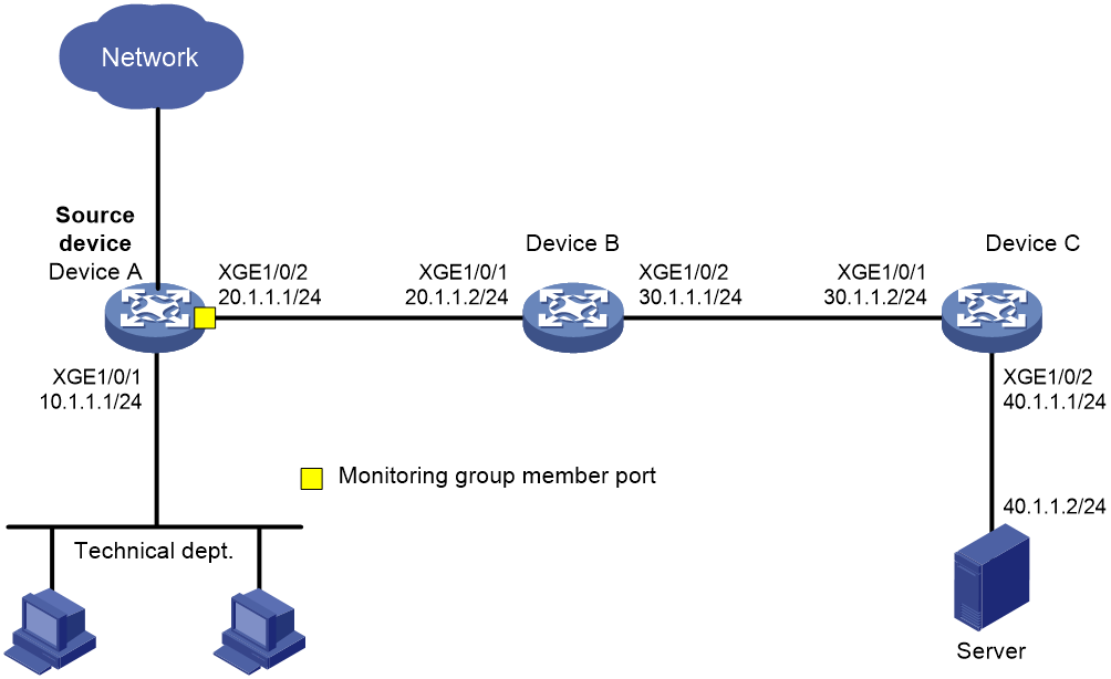
Network configuration
On a Layer 3 network, Device A, Device B, Device C, and Server are connected as shown in Figure 15. Device A is connected to the technical department through Ten-GigabitEthernet 1/0/1.
Configure flow mirroring to enable the server to monitor the Internet accessing traffic of the technical department through the mirrored packets forwarded by Device C.
Procedure
1. Configure IP addresses and subnet masks for interfaces as shown in Figure 15. (Details not shown.)
2. Configure Device A:
# Configure OSPF.
[DeviceA] ospf 1
[DeviceA-ospf-1] area 0
[DeviceA-ospf-1-area-0.0.0.0] network 10.1.1.0 0.0.0.255
[DeviceA-ospf-1-area-0.0.0.0] network 20.1.1.0 0.0.0.255
[DeviceA-ospf-1-area-0.0.0.0] quit
[DeviceA-ospf-1] quit
# Create advanced IPv4 ACL 3000. Configure a rule to match the Internet accessing traffic with port 80 from the technical department.
[DeviceA] acl advanced 3000
[DeviceA-acl-ipv4-adv-3000] rule permit tcp source 10.1.1.1 0.0.0.255 destination-port eq www
[DeviceA-acl-ipv4-adv-3000] quit
# Create monitoring group 1. Assign interface Ten-GigabitEthernet 1/0/2 to the monitoring group as a member port. Alternatively, do not specify a specific member port. In this case, the device forwards the packets by automatically looking up the source IP and destination IP in the routing table. Encapsulate the mirrored packets with destination IP address 40.1.1.1 and source IP address 20.1.1.1.
[DeviceA] monitoring-group 1
[DeviceA-monitoring-group-2] monitoring-port ten-gigabitethernet 1/0/2 destination-ip 40.1.1.1 source-ip 20.1.1.1
# Create traffic class tech_c, and use ACL 3000 as a match criterion.
[DeviceA] traffic classifier tech_c
[DeviceA-classifier-tech_c] if-match acl 3000
[DeviceA-classifier-tech_c] quit
# Create traffic behavior tech_b, and configure an action of mirroring traffic to monitoring group 1.
[DeviceA] traffic behavior tech_b
[DeviceA-behavior-tech_b] mirror-to monitoring-group 1
[DeviceA-behavior-tech_b] quit
# Create QoS policy tech_p, and associate traffic class tech_c with traffic behavior tech_b.
[DeviceA] qos policy tech_p
[DeviceA-qospolicy-tech_p] classifier tech_c behavior tech_b
[DeviceA-qospolicy-tech_p] quit
# Apply QoS policy tech_p to the inbound direction of interface Ten-GigabitEthernet 1/0/1.
[DeviceA] interface ten-gigabitethernet 1/0/1
[DeviceA-Ten-GigabitEthernet1/0/1] qos apply policy tech_p inbound
[DeviceA-Ten-GigabitEthernet1/0/1] quit
3. Configure Device B:
# Configure OSPF.
<DeviceB> system-view
[DeviceB] ospf 1
[DeviceB-ospf-1] area 0
[DeviceB-ospf-1-area-0.0.0.0] network 20.1.1.0 0.0.0.255
[DeviceB-ospf-1-area-0.0.0.0] network 30.1.1.0 0.0.0.255
[DeviceB-ospf-1-area-0.0.0.0] quit
[DeviceB-ospf-1] quit
4. Configure Device C:
# Configure OSPF.
[DeviceC] ospf 1
[DeviceC-ospf-1] area 0
[DeviceC-ospf-1-area-0.0.0.0] network 30.1.1.0 0.0.0.255
[DeviceC-ospf-1-area-0.0.0.0] network 40.1.1.0 0.0.0.255
[DeviceC-ospf-1-area-0.0.0.0] quit
[DeviceC-ospf-1] quit
Verifying the configuration
Verify that the server can monitor the Internet accessing traffic with port 80 from the technical department on the server.
Specifying tunnel interfaces as member ports
Introduction
A monitoring group with a tunnel interface as a member port is implemented as follows:
1. Configure a monitoring group on the source device, and configure a tunnel interface as a member port of the monitoring group.
2. Configure a QoS policy on the source device. In the QoS policy, configure a traffic class to match packets, and configure a traffic behavior to mirror traffic to a monitoring group.
3. The device copies a matching packet to the monitoring group. The packet is forwarded to the tunnel interface on the destination device through the GRE tunnel.
4. The destination device forwards the packet received on the physical interface of the tunnel interface to the data monitoring device.
The destination device needs to recognize the mirrored packet received on the physical interface of the tunnel interface and forward the packet to the data monitoring device. To do that, use one of the following methods on the destination device:
¡ Similar to the configuration of Layer 3 remote port mirroring in tunnel mode, perform the following tasks on the destination device:
- Configure a local mirroring group.
- Configure the physical interface of the tunnel interface as the source port.
- Configure the port connecting to the data monitoring device as the monitor port.
Use this method when the physical interface of the tunnel interface is exclusively used for processing mirrored packets.
¡ Configure flow mirroring on the destination device as follows:
- Configure a traffic class to match the mirrored packets received on the physical interface of the tunnel interface.
- Configure a traffic behavior to mirror packets to the interface connecting to the data monitoring device in a traffic behavior.
- Create a QoS policy, and associate the traffic class with the traffic behavior.
- Apply the QoS policy.
¡ Configure a QoS policy on the destination device as follows:
- Configure a traffic class to match the mirrored packets received on the physical interface of the tunnel interface.
- Configure a behavior to redirect packets to the interface connecting to the data monitoring device.
- Create a QoS policy, and associate the traffic class with the traffic behavior.
- Apply the QoS policy.
5. The data monitoring device decapsulates the packet and analyzes the packet contents.
Example: Flow-mirroring traffic to a monitoring group with a tunnel interface as the member port
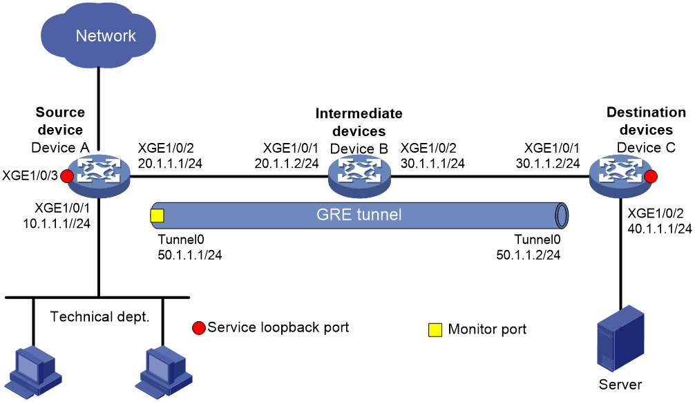
Network configuration
As shown in Figure 16, the technical department uses the 10.1.1.1/24 subnet. Configure flow mirroring, so that the server can monitor the Internet accessing traffic from the technical department.
Procedure
1. Configure IP addresses and subnet masks for interfaces as shown in Figure 16. (Details not shown.)
2. Configure Device A:
# Create service loopback group 1, and specify tunnel services for the group.
<DeviceA> system-view
[DeviceA] service-loopback group 1 type tunnel
# Assign Ten-GigabitEthernet 1/0/3 to service loopback group 1.
[DeviceA] interface ten-gigabitethernet 1/0/3
[DeviceA-Ten-GigabitEthernet1/0/3] port service-loopback group 1
All configurations on the interface will be lost. Continue?[Y/N]:y
[DeviceA-Ten-GigabitEthernet1/0/3] quit
# Create GRE tunnel interface Tunnel 0. Assign an IP address and mask to the interface.
[DeviceA] interface tunnel 0 mode gre
[DeviceA-Tunnel0] ip address 50.1.1.1 24
# Specify a source IP address and destination IP address for interface Tunnel 0.
[DeviceA-Tunnel0] source 20.1.1.1
[DeviceA-Tunnel0] destination 30.1.1.2
[DeviceA-Tunnel0] quit
# Configure OSPF.
[DeviceA] ospf 1
[DeviceA-ospf-1] area 0
[DeviceA-ospf-1-area-0.0.0.0] network 10.1.1.0 0.0.0.255
[DeviceA-ospf-1-area-0.0.0.0] network 20.1.1.0 0.0.0.255
[DeviceA-ospf-1-area-0.0.0.0] quit
[DeviceA-ospf-1] quit
# Create advanced IPv4 ACL 3000. Configure a rule to match the Internet accessing traffic with port 80 from the technical department.
[DeviceA] acl advanced 3000
[DeviceA-acl-ipv4-adv-3000] rule permit tcp source 10.1.1.1 0.0.0.255 destination-port eq www
[DeviceA-acl-ipv4-adv-3000] quit
# Create monitoring group 1, and assign interface Tunnel 0 to the monitoring group.
<DeviceA> system-view
[DeviceA] monitoring-group 1
[DeviceA-monitoring-group-1] monitoring-port tunnel 0
# Create traffic class tech_c, and use ACL 3000 as a match criterion.
[DeviceA] traffic classifier tech_c
[DeviceA-classifier-tech_c] if-match acl 3000
[DeviceA-classifier-tech_c] quit
# Create traffic behavior tech_b, and configure an action of mirroring traffic to monitoring group 1.
[DeviceA] traffic behavior tech_b
[DeviceA-behavior-tech_b] mirror-to monitoring-group 1
[DeviceA-behavior-tech_b] quit
# Create QoS policy tech_p, and associate traffic class tech_c with traffic behavior tech_b.
[DeviceA] qos policy tech_p
[DeviceA-qospolicy-tech_p] classifier tech_c behavior tech_b
[DeviceA-qospolicy-tech_p] quit
# Apply QoS policy tech_p to the inbound direction of interface Ten-GigabitEthernet1/0/1.
[DeviceA] interface ten-gigabitethernet 1/0/1
[DeviceA-Ten-GigabitEthernet1/0/1] qos apply policy tech_p inbound
[DeviceA-Ten-GigabitEthernet1/0/1] quit
3. Configure Device B:
# Configure OSPF.
<DeviceB> system-view
[DeviceB] ospf 1
[DeviceB-ospf-1] area 0
[DeviceB-ospf-1-area-0.0.0.0] network 20.1.1.0 0.0.0.255
[DeviceB-ospf-1-area-0.0.0.0] network 30.1.1.0 0.0.0.255
[DeviceB-ospf-1-area-0.0.0.0] quit
[DeviceB-ospf-1] quit
4. Configure Device C:
# Create service loopback group 1, and specify tunnel services for the group.
<DeviceC> system-view
[DeviceC] service-loopback group 1 type tunnel
# Assign Ten-GigabitEthernet 1/0/3 to service loopback group 1.
[DeviceC] interface ten-gigabitethernet 1/0/3
[DeviceC-Ten-GigabitEthernet1/0/3] port service-loopback group 1
All configurations on the interface will be lost. Continue?[Y/N]:y
[DeviceC-Ten-GigabitEthernet1/0/3] quit
# Create GRE tunnel interface Tunnel 0. Assign an IP address and mask to the interface.
[DeviceC] interface tunnel 0 mode gre
[DeviceC-Tunnel0] ip address 50.1.1.2 24
# Specify a source IP address and destination IP address for interface Tunnel 0.
[DeviceC-Tunnel0] source 30.1.1.2
[DeviceC-Tunnel0] destination 20.1.1.1
[DeviceC-Tunnel0] quit
# Configure OSPF.
[DeviceC] ospf 1
[DeviceC-ospf-1] area 0
[DeviceC-ospf-1-area-0.0.0.0] network 30.1.1.0 0.0.0.255
[DeviceC-ospf-1-area-0.0.0.0] network 40.1.1.0 0.0.0.255
[DeviceC-ospf-1-area-0.0.0.0] quit
[DeviceC-ospf-1] quit
# Create local mirroring group 1.
[DeviceC] mirroring-group 1 local
# Configure Ten-GigabitEthernet 1/0/1 as a source port and Ten-GigabitEthernet 1/0/2 as a monitor port for local mirroring group 1.
[DeviceC] mirroring-group 1 mirroring-port ten-gigabitethernet 1/0/1 inbound
[DeviceC] mirroring-group 1 monitor-port ten-gigabitethernet 1/0/2
Verifying the configuration
Verify that the server can monitor the Internet accessing traffic with port 80 from the technical department on the server.
Hardware and flow mirroring compatibility matrix
|
S6800 S6860 S6861 S6820 |
S6805 S6850 S9850 S9820-64H |
S9820-8C |
S12500-X S12500X-AF |
S12500R S12500CR |
|
|
Item (below) |
|||||
|
Max number of flow mirroring policies |
4 |
4 |
4 |
15 per chip. To identify ports on the same chip, execute the debug port mapping slot command in probe view. Ports with the same unit value are on the same chip. |
15 per chip. To identify ports on the same chip, execute the debug port mapping slot command in probe view. Ports with the same unit value are on the same chip. |
|
Destination interface types for flow mirroring |
· Layer 2 or Layer 3 Ethernet interfaces · Layer 2 aggregate interfaces · Member ports of Layer 2 or Layer 3 aggregate interfaces NOTE: In the outbound direction, only unicast packets can be mirrored, and any other action cannot be configured. |
· Layer 2 or Layer 3 Ethernet interfaces · Layer 2 aggregate interfaces · Member ports of Layer 2 or Layer 3 aggregate interfaces |
· Layer 2 or Layer 3 Ethernet interfaces · Member ports of Layer 2 or Layer 3 aggregate interfaces |
· Layer 2 or Layer 3 Ethernet interfaces · Layer 2 aggregate interfaces · Member ports of Layer 2 or Layer 3 aggregate interfaces |
· Layer 2 or Layer 3 Ethernet interfaces · Layer 2 aggregate interfaces · Member ports of Layer 2 or Layer 3 aggregate interfaces |
|
Policy application destinations (directions) |
· Layer 2 or Layer 3 Ethernet interfaces (inbound) · Layer 3 Ethernet subinterfaces (inbound) · Layer 2 or Layer 3 aggregate interfaces (inbound) · Layer 3 aggregate subinterfaces (inbound) · VLANs (inbound) · Globally (inbound) |
· Layer 2 or Layer 3 Ethernet interfaces (inbound and outbound) · Layer 3 Ethernet subinterfaces (inbound and outbound) · Layer 2 aggregate interfaces (inbound and outbound) · Layer 3 aggregate interfaces (inbound) · Layer 3 aggregate subinterfaces (inbound) · VLANs (inbound) · Globally (inbound) NOTE: When a policy is applied in the outbound direction, you cannot configure any other action in the policy. |
· Layer 2 Ethernet interfaces (inbound and outbound). Flow mirroring ERSPAN is not supported in the outbound direction. · Layer 3 Ethernet interfaces (inbound) · Layer 3 Ethernet subinterfaces (inbound) · Layer 2 or Layer 3 aggregate interfaces (inbound) · Layer 3 aggregate subinterfaces (inbound) · VLANs (inbound) · Globally (inbound) NOTE: When a policy is applied in the outbound direction, you cannot configure any other action in the policy. |
· Layer 2 or Layer 3 Ethernet interfaces (inbound and outbound) · Layer 3 Ethernet subinterfaces (inbound and outbound) · Layer 2 or Layer 3 aggregate interfaces (inbound and outbound) · Layer 3 aggregate subinterfaces (inbound and outbound) · VLANs (inbound and outbound) · Globally (inbound and outbound) |
· Layer 2 or Layer 3 Ethernet interfaces (inbound and outbound) · Layer 3 Ethernet subinterfaces (inbound and outbound) · Layer 2 or Layer 3 aggregate interfaces (inbound and outbound) · Layer 3 aggregate subinterfaces (inbound and outbound) · VLANs (inbound and outbound) · Globally (inbound and outbound) |
|
Max number of destination interfaces for flow mirroring per policy |
4 |
1 |
1 |
||
|
Flow mirroring to monitoring groups |
Not supported |
Up to 15 monitoring groups are supported. The member ports can be multiple Layer 2 or Layer 3 Ethernet interfaces, multiple Layer 2 aggregate interfaces, or one GRE tunnel interface |
Up to 15 monitoring groups are supported. The member ports can be multiple Layer 2 or Layer 3 Ethernet interfaces, multiple Layer 2 aggregate interfaces, or one GRE tunnel interface |
||
|
Packet sampling |
No |
Yes |
Yes |
No |
No |
|
Mirroring cross IRF member devices or cards |
Supported |
· Not supported by flow mirroring in loopback mode · Supported by flow mirroring in encapsulation parameter mode |
N/A |
Mirroring cross IRF member devices: · Type H cards: Supported · Type F cards: Not supported Cross-card mirroring: Supported |
· Mirroring cross IRF member devices: N/A · Cross-card mirroring: Supported |
|
ERSPAN: Specifying the loopback parameter for flow mirroring to interfaces |
Directly specifying an outgoing interface is supported |
Both directly specifying an outgoing interface and specifying an outgoing interface through route lookup are supported However, the source interfaces and the destination interfaces must reside on the same IRF member device |
Both directly specifying an outgoing interface and specifying an outgoing interface through route lookup are supported |
Not supported |
Not supported |
|
ERSPAN: Configuring encapsulation parameters for flow mirroring to interfaces |
Directly specifying an outgoing interface is supported |
Both directly specifying an outgoing interface and specifying an outgoing interface through route lookup are supported |
Both directly specifying an outgoing interface and specifying an outgoing interface through route lookup are supported |
Not supported |
Not supported |
|
ERSPAN: Configuring encapsulation parameters for monitoring group member ports in flow mirroring to monitoring groups |
Not supported |
Not supported |
Supported |
||
|
ERSPAN: Flow mirroring to a monitoring group with the member port as a tunnel interface |
Not supported |
Supported |
Supported |
||
