- Released At: 07-03-2023
- Page Views:
- Downloads:
- Table of Contents
- Related Documents
-
Intelligent Radio Resource Adjustment Technology White Paper
Copyright © 2023 New H3C Technologies Co., Ltd. All rights reserved.
No part of this manual may be reproduced or transmitted in any form or by any means without prior written consent of New H3C Technologies Co., Ltd.
Except for the trademarks of New H3C Technologies Co., Ltd., any trademarks that may be mentioned in this document are the property of their respective owners.
The information in this document is subject to change without notice.
Non-overlapping channel group optimization for 2.4 GHz radios
Auto transmit power adjustment
Transmit power adjustment through neighbor reports
Transmit power adjustment through RSSI packets
High-density AP deployment optimization
Cloud-based RRM implementation
Cloud-based RRM for AC+fit AP networks
Cloud-based RRM for cloud-managed AP networks
Overview
Technical background
With the popularization of wireless networks and the rapid growth of wireless users, wireless network O&M is getting increasingly difficult. At the same time, increasing user demands for network applications also makes it urgent for WLANs to provide high-quality network experience in real time. Traditional O&M relies on manual adjustment of radio parameters (channel, power, and bandwidth), which mainly have the following problems:
· Users might feel difficult to configure radio parameters for lack of wireless network knowledge.
· Manual adjustment is complicated and time-consuming in a large-sized network.
· Manual adjustment cannot respond in time to network changes. Wireless network performance cannot keep the best state when network changes occur.
· Manual adjustment takes a long time and has a high cost, which makes it hard to form a high-efficiency closed-loop.
· Issues cannot be detected immediately, which affects user experience.
To resolve the issue, intelligent Radio Resource Management (RRM) is introduced to adjust channel, power, and bandwidth parameters of radios automatically in case of network changes.
Intelligent RRM features are available in the following forms:
· AC-based RRM—Performs calibration based on local data.
· Cloud-based RRM—Requires device connection to the public cloud or private cloud.
When both AC-based RRM and cloud-based RRM are configured, cloud-based RRM is responsible for unified resource scheduling and adjustment.
Benefits
RRM monitors wireless environment, collects and analyzes wireless environment data, and uses intelligent calibration algorithms to generate radio optimization policies. H3C intelligent RRM provides the following benefits:
· Sense network changes in time and make corresponding adjustments to reduce the impact of network changes on user experience.
· Reduce the required O&M manpower, time, and costs.
· Adjust radio parameters automatically to provide continuous optimization for wireless services.
Intelligent RRM is applicable to the following scenarios:
· Small- to medium-sized networks lacking professional O&M personnel.
· Large-sized networks with a large number of APs, such as offices, universities and colleges, and large-scale shopping malls.
|
· |
NOTE: Intelligent RRM adjusts radio channel, transmit power, and bandwidth parameters automatically. For scenarios that require fixed channel, transmit power, or bandwidth, such as healthcare roaming and AGV networks, do not configure intelligent RRM as a best practice. |
Key elements
· Channel adjustment
In a WLAN, a radio can only work on a limited number of channels, where there may be a lot of interference from both wireless devices and non-wireless devices, such as radar transmitters and microwave ovens. With channel adjustment, the system automatically assigns an optimal channel for each radio in real time to avoid co-channel interference and interference from other radio sources.
· Power adjustment
Traditional power control sets the transmit power of a radio to the maximum value to maximize the signal coverage, which causes unnecessary interference to other wireless devices and sticky clients. This reduces the overall capacity and user experience of the system, and cannot meet the high throughput requirement.
Power adjustment of intelligent RRM can ensure the signal coverage and reduce unnecessary interference at the same time by allocating a reasonable transmit power for each radio.
· Bandwidth adjustment
Configuring all radios to use the maximum bandwidth increases the negotiated rate between AP and client, but causes severs co-channel interference due to limited wireless channels.
Bandwidth adjustment of intelligent RRM can balance negotiated rate and interference and thereby improve the capacity of the entire network.
AC-based RRM implementation
Mechanism
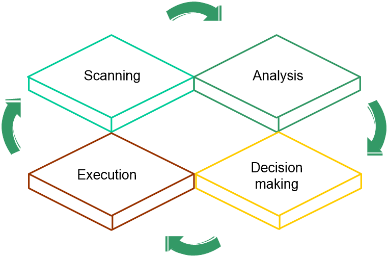
AC-based RRM uses the computing capacity to analyze the local data. It operates as follows:
1. Scanning
APs scan channels regularly after coming online and report collected information to the AC at specific intervals. To avoid affecting wireless services, APs scan channels only when no service traffic is being transmitted.
2. Analyzing
The AC analyzes the received information, including channel quality, channel interference conditions, and adjacent AP distribution, and builds a model of the surrounding network with real-time awareness of network changes for decision making.
3. Decision making
Based on the analysis result, the AC uses intelligent algorithms to adjust and optimize radio resources, and automatically evaluates the impact of the adjustment on the network to ensure that the system is reliably adjusted to accommodate changes in the WLAN.
4. Execution
The AC sends the adjustment policy to the target AP, and the AP adjusts the channel, bandwidth, and transmit power as instructed in the policy. Users can view the history of AP radio adjustment on the AC.
The AC continuously monitors the network environment and records any wireless environment changes for the next round of adjustment.
Figure 1 AC-based RRM working mechanism
Auto channel adjustment
Introduction
Radio frequency interference can affect user experience of wireless networks. Common radio frequency interference includes co-channel interference and adjacent channel interference.
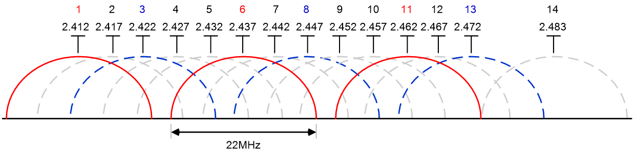
· Co-channel interference—Radios of APs operating on the same channel interfere with each other. As shown in Figure 2, the 2.4 GHz band has four groups of non-overlapping channels of (1, 6, 11), (2, 7, 12), (3, 8, 13), (4, 9, 14), which are very limited. Therefore, in real cases, one channel is often used by multiple APs, which causes co-channel interference.
· Adjacent channel interference—Radios of APs radios operating on different channels interfere with each other. For APs with different center frequencies, overlapping radio bandwidth of the APs will cause adjacent channel interference. This issue often occurs in the scenario when high density of APs are deployed and the 2.4 GHz APs use different non-overlapping channel groups with the transmit power too strong or the AP space too close. For example, if H3C APs use the (1, 6, 11) non-overlapping channel group and APs of another vendor use the (3, 8, 13) non-overlapping channel group, serious adjacent channel interference might occur.
Figure 2 2.4 GHz channel spectrum
For co-channel interference, Carrier Sense Multiple Access with Collision Avoidance (CSMA/CA) can be used to resolve the issue. For adjacent channel interference, the impact on user experience is severer and CSMA/CA cannot resolve the issue completely.
When you use channel adjustment to reduce radio frequency interference caused by high-density AP deployment, the following elements must be considered:
· Select suitable channels.
Auto channel adjustment can make sure each AP uses the optimal channel. For more information, see "Channel adjustment."
· Select suitable channel groups.
Auto channel adjustment can monitor the channel groups used by APs of other vendors and use optimization algorithm to reduce the adjacent channel interference in the multi-vendor AP deployment scenario. For more information, see "Non-overlapping channel group optimization for 2.4 GHz radios."
Channel adjustment
Factors that can trigger auto channel adjustment include the following:
· Error code rate—Physical layer error code rate and CRC error rate. CRC error rate shows the proportion of packets with CRC errors among all 802.11 packets.
· Interference—802.11 interference and non-802.11 interference.
· Channel usage—Proportion of channel resources used for packet transmitting and receiving.
· Retransmission—Packets retransmitted because an AP fails to receive an ACK.
· Radar—Radar signals detected in the current working channel.
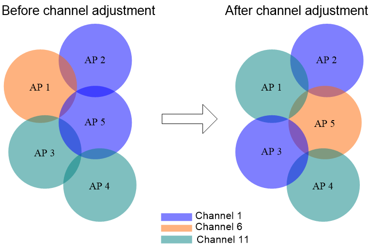
If one or multiple such issues exist, the AC selects an optimal channel as the backup channel. If the working channel quality drops below the threshold, the AP uses the backup channel as the working channel. For example, as shown in Figure 3, before channel adjustment, AP 2 and its neighbor AP 5 operate on the same channel and AP 3 and its neighbor AP 4 operate on the same channel. After adjustment, adjacent APs operate on different channels, which minimizes co-channel interference.
Figure 3 Automatic channel adjustment
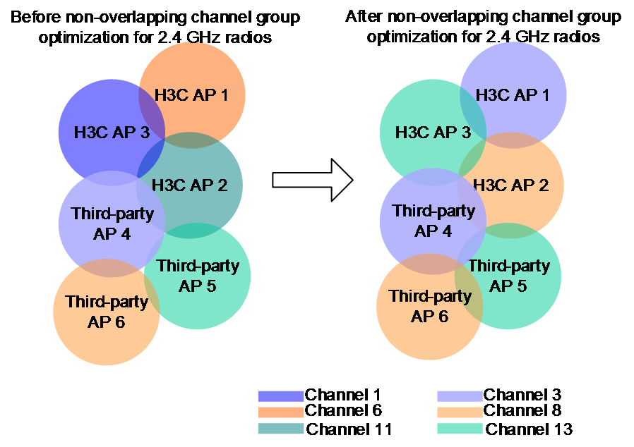
Non-overlapping channel group optimization for 2.4 GHz radios
In high-density deployment with APs of different vendors, severe interference might occur for 2.4 GHz radios because these APs cannot be managed in a unified manner and might use different non-overlapping channel groups. This greatly affects the user experience.
With this feature enabled, H3C APs monitor the operating channels of the neighbor APs for 2.4 GHz radios dynamically and the system adopts the non-overlapping channel group most used by neighbor radios on third-party APs during auto channel adjustment. This operation can reduce the adjacent channel interference between APs of different vendors to the maximum degree.
Neighbor radio includes the following types:
· Managed neighbor—Detected AP radios managed by the same AC.
· Unmanaged neighbor—Detected AP radios managed by another AC.
With this feature enabled, the device performs non-overlapping channel group optimization for 2.4 GHz radios during auto channel adjustment when all the following conditions are met:
· The total number of neighbors reaches or exceeds the configured threshold.
· The unmanaged neighbor ratio (unmanaged neighbors/total neighbors) reaches or exceeds the configured threshold.
· The unmanaged neighbor ratio for a single non-overlapping channel group (unmanaged neighbors/total neighbors) reaches or exceeds the configured threshold.
The effect of non-overlapping channel group optimization for 2.4 GHz radios and auto channel adjustment is shown in Figure 4. Each AP has only one radio enabled. Before the optimization, APs of different vendors use different non-overlapping groups. H3C AP 3 operates on channel 1 and third-party AP 4 operates on channel 3, which has severe adjacent channel interference. After the optimization, the H3C APs use the same non-overlapping channel groups as the third-party APs.
Figure 4 Non-overlapping channel group optimization for 2.4 GHz radios
Auto transmit power adjustment
Introduction
The AC determines whether transmit power adjustment is required for an AP based on the following factors:
· Signal strength of neighbor APs detected by the AP—Used to identify whether the current transmit power is reasonable.
· Signal strength of the AP detected by clients—Used to identify if coverage holes exist. The system must also take the roaming logics of clients into consideration to exclude sticky clients to prevent improper transmit power adjustment from exacerbating the sticky client issue.
When you use automatic transmit power adjustment, the following elements must be considered:
· When APs are deployed properly, the AC obtains AP transmit power information from the neighbor report and uses optimization algorithm to adjust the transmit power to an appropriate value. For more information, see "Transmit power adjustment through neighbor reports."
· In high location installation, blocking, and other special scenarios, the AC must adjust the AP transmit power and ensure a good RSSI at the same time. For more information, see "Transmit power adjustment through RSSI packets."
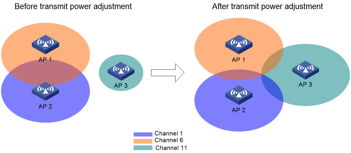
Transmit power adjustment through neighbor reports
Based on neighbor reporting, the AC obtains information about the transmit power of a radio from the neighbor reports uploaded by other radios, and compare the current radio's transmit power with the transmit power adjustment threshold.
· If the radio's transmit power is higher than the threshold and the gap reaches a specific value, the system decreases the transmit power.
· If the radio's transmit power is lower than the threshold and the gap reaches a specific value, the system increases the transmit power.
As shown in Figure 5, each AP has only one radio enabled. Before the adjustment, a coverage hole exists and the transmit power of AP 1 and the transmit power of AP 2 are too high. After the adjustment, the transmit power of AP 3 is increased to remove the coverage hole and the transmit power of AP 1 and the transmit power of AP 2 are decreased to reduce co-channel interference.
Figure 5 Transmit power control
Transmit power adjustment through RSSI packets
When APs are not properly deployed, adjusting transmit power through only neighbor reports might not ensure a good RSSI. Typical scenarios are as follows:
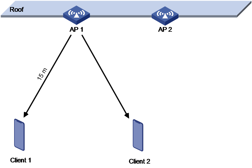
· APs are installed at a high location.
As shown in Figure 6, AP 1 and AP 2 are installed at a high location and strong transmit power can be detected between the APs. In this case, the AC reduces the AP transmit power to reduce radio interference. However, reducing the transmit power decreases the RSSI because the APs are installed far from the clients. This leads to a poor user experience such as weak RSSI and low negotiation rate.
Figure 6 AP high location installation scenario
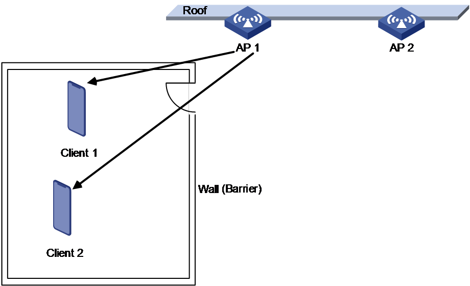
· Obstacles exist between APs and clients.
As shown in Figure 7 and Figure 8, the APs are installed at a high location and a ceiling exists between the APs and the clients. Strong transmit power can be detected between the APs, so the AC reduces the AP transmit power to reduce radio interference. However, reducing the transmit power decreases the RSSI because the ceiling causes severe signal attenuation.
Figure 7 Obstacle scenario (1)

Figure 8 Obstacle scenario (2)
In the above scenarios, the AC supports coverage hole detection through the RSSI packets sent from the clients. The AC operates as follows:
1. Verify whether the RSSI packets are weak signal packets. If the RSSI value is lower than the configured RSSI threshold, the RSSI packets are weak signal packets.
2. Verify whether the clients are weak signal clients. A client is verified as weak signal client when all the following criteria are met:
¡ The number of weak signal packets for the client reaches or exceeds the configured threshold.
¡ The weak signal packet ratio for the client reaches or exceeds the configured threshold.
3. Verify whether radio coverage holes exist. Radio coverage holes exist when all the following criteria are met:
¡ The number of associated weak signal clients on the radio reaches or exceeds the configured threshold.
¡ The ratio of associated weak signal clients on the radio reaches or exceeds the configured threshold.
If coverage holes are detected, the AC will increase the AP transmit power automatically to ensure the user experience on the clients.
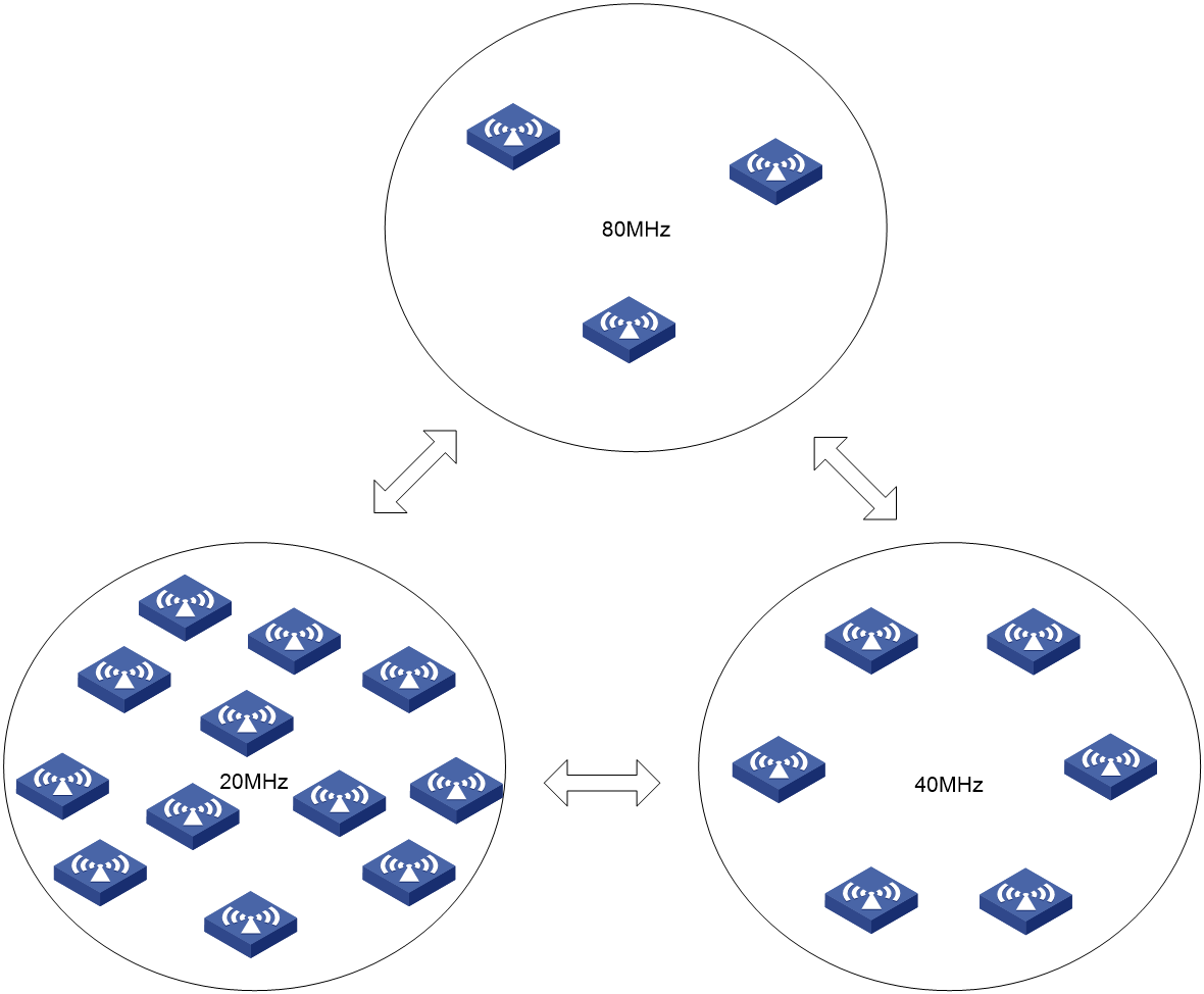
Auto bandwidth adjustment
Auto bandwidth adjust uses the channel binding technology and takes AP density, AP model, and client quantity to assign a reasonable bandwidth for each radio. It follows the following principles:
· For low AP density, decrease radio bandwidth to reduce interference.
· For high AP density, increase radio bandwidth to increase the data transmission speed.
· Reduce overlapping channels for adjacent APs as much as possible to minimize co-channel interference.
· Ensure that APs and clients can negotiate appropriate rates, ensuring the access rate of clients and increasing the capacity of the entire network.
The AC performs channel quality evaluation at the end of each auto bandwidth adjustment period and decides whether to adjust the bandwidth based on the evaluation result.
As shown in Figure 9, when the AC detects that too many neighbor APs and clients exist for an AP, it decreases the radio bandwidth to reduce interference. When the AC detects that only a few neighbor APs and clients exist for an AP, it increases the radio bandwidth to increase the transmission speed and network capacity.
Figure 9 Automatic bandwidth adjustment
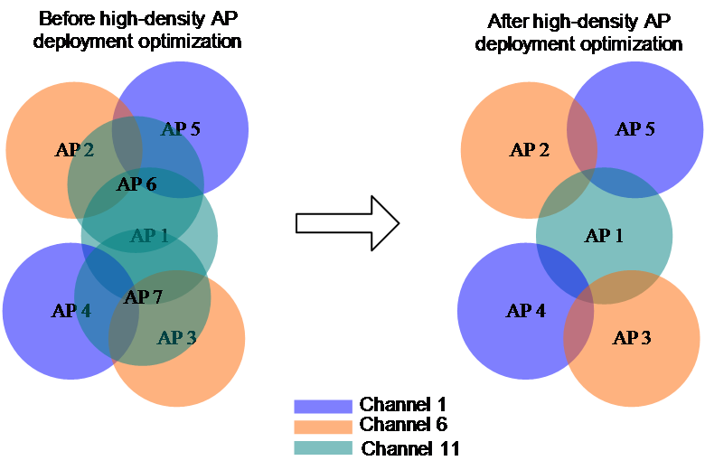
High-density AP deployment optimization
In public places such as stadiums and large conference centers, wireless networks often feature high density and high concurrency. To satisfy the large number of user access requirements, a large number of APs are deployed. However, because the radio resources are limited, when APs are deployed in high density, interference between APs becomes very strong.
High-density AP deployment optimization can calculate and identify redundant APs and help users to disable redundant radios on these APs. This can lower the radio interference between APs in high-density scenarios.
For example, as shown in Figure 10, each AP has only one radio enabled. Before high-density AP deployment optimization, AP 1, AP 6, and AP 7 operate on channel 11 and severe channel overlapping and interference exist. After the optimization, radios on AP 6 and AP 7 that operate on channel 11 are disabled, which reduce radio interference and ensure the wireless network coverage.
Figure 10 High-density AP deployment optimization
Cloud-based RRM implementation
One-key optimization
Introduction
One-key optimization of cloud-based RRM is applicable for startup deployment and manual optimization. It is available in the Smart O&M section on the Cloudnet platform at https://oasiscloud.h3c.com and allows users to optimize the network through a click.
Mechanism
One-key optimization operates as follows:
1. Examine device operation status and cloud connections.
2. Trigger devices to scan the network and obtain the AP configuration and scanning data.
3. Calculate radios to be adjusted based on the collected data.
4. Use the optimization algorithm to generate the radio adjustment policies.
5. Deploy the policies to devices for radio adjustment.
6. Save the adjustment record.
Implementation
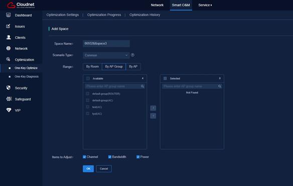
Optimization target customization
One-key optimization optimizes the network based on spaces.
· Global space—Optimize all APs in the site. The space as created automatically as the site was created and cannot be deleted.
· Customized space—Optimize APs by room or AP group, or optimize the selected APs. You can select a scenario type, and select an AP range.
Figure 11 Customizing optimization options
Process visibility
One-key optimization includes four steps: checking, scanning, optimization, and completion. You can view the process from the Web interface.
Figure 12 Process visibility

Optimization result displaying
If the optimization succeeds, the system displays information about the process, including AP quantity, start time, time consumption, and configuration comparison. If the optimization fails, the system displays the failure reason.
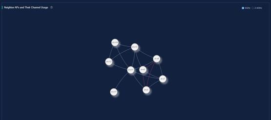
You can view the optimization history in the past week, including the neighbor AP channel, AP channel distribution, adjusted transmit power statistics, and adjusted APs.
· Neighbor APs and their channel usage—Displays channel relations between adjacent APs. A gray line indicates mutual neighbor relation, and a red line indicates that the radios use the same channel. You can view channel conflict conditions between adjacent APs in this graph.
Figure 13 Neighbor APs and channel usage
· AP distribution by channel—Displays the number of APs on each channel and the channel usage before and after the optimization.
Figure 14 AP distribution by channel

· Power adjustment statistics—Displays the power adjustment details.
Figure 15 Power adjustment statistics

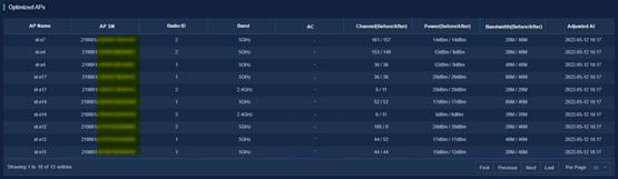
· Optimized APs—Displays detailed optimization information for each AP.
Figure 16 Optimized APs
Typical applications
AC-based RRM
As shown in Figure 17, AC-based RRM can be used only in AC+fit AP networks for the AC to optimize all the managed APs.
Cloud-based RRM
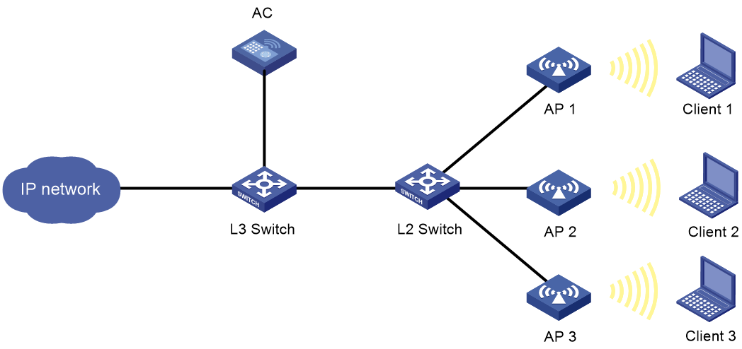
Cloud-based RRM for AC+fit AP networks
Cloud-based RRM can be used in an AC+fit AP network. As shown in Figure 18, the AC established a cloud connection to the cloud platform and uses CAPWAP tunnels to communicate with APs.
Cloud-based RRM for AC+fit AP networks operates as follows:
1. APs report radio information to the AC, and the AC reports the information to the cloud platform.
2. The cloud platform analyzes the information and deploys radio parameters to be adjusted to the AC.
Figure 18 Cloud-based RRM for AC+fit AP networks

Cloud-based RRM for cloud-managed AP networks
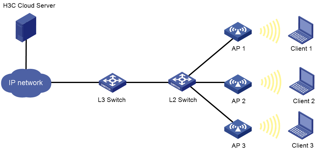
As shown in Figure 19, Cloud-based RRM can be used in a cloud-managed AP network. This feature is not available on APs that does not support cloud management.
Figure 19 Cloud-based RRM for cloud-managed AP networks