- Released At: 12-10-2023
- Page Views:
- Downloads:
- Table of Contents
- Related Documents
-
3 Technical advancement roadmap
4.8 SRv6 and MPLS interworking
4.12 Subinterface channelization
4.15 Slice ID-based network slicing
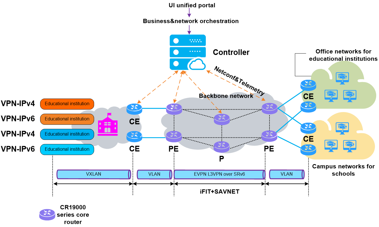
5.1 IPv6+ carrier cloud-network convergence solution
5.2 IPv6+ carrier cloud IPTV solution
5.3 IPv6+ e-government extranet solution
1 Technical background
The rapid development of emerging fields such as 5G, Internet of Things (IoT), and cloud computing has led to a significant increase in network scale, complexity, business diversity, and demand for intelligence, posing new challenges to network technologies.
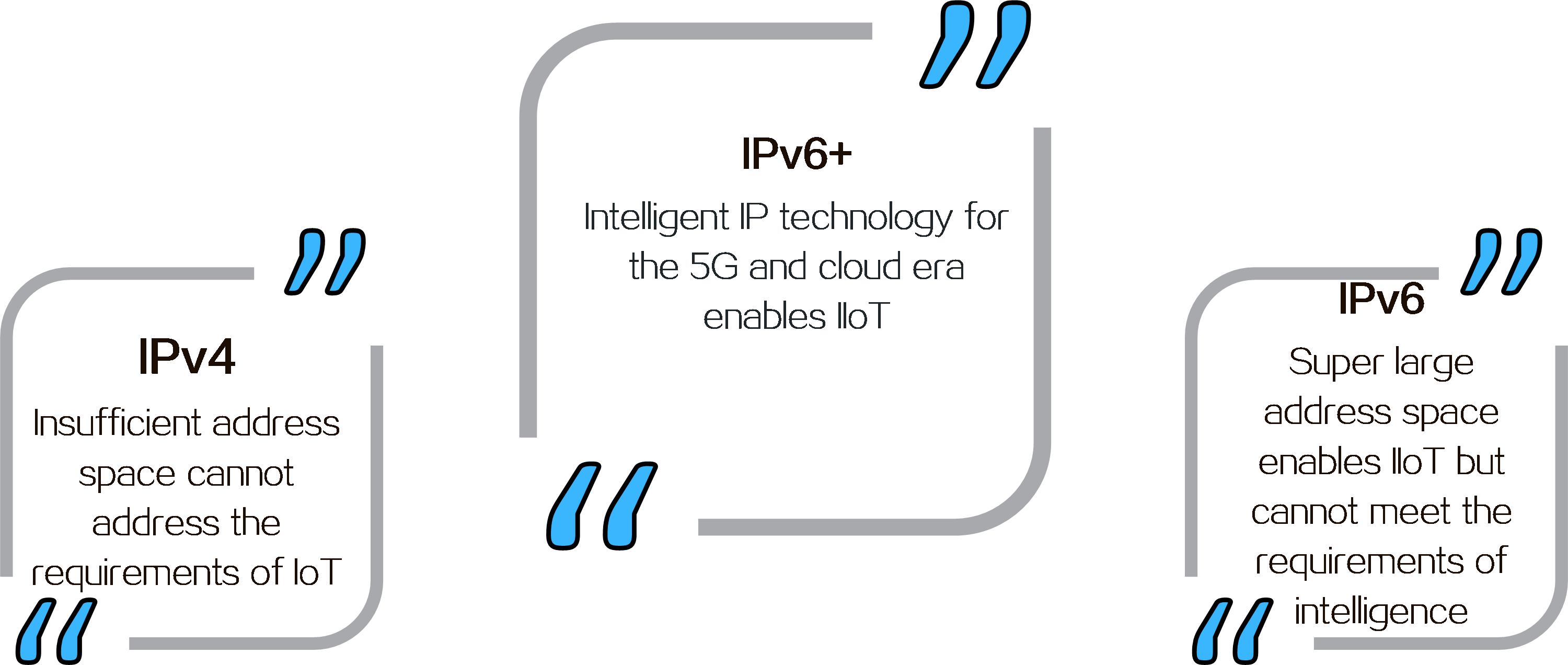
The first-generation network layer protocol, IPv4, has a limited address space, which cannot meet the requirements of IoT. The second-generation network layer protocol, IPv6, uses 128-bit addresses and can provide 3.4×10^38 addresses, enabling broader connections for the Internet and IoT, serving as the foundation for the Internet of Everything (IoE). However, IoE is far from enough in the context of booming new businesses. Business differentiation and AIOps must also be considered.
IPv6+ has made significant innovations based on the IPv6 protocol, such as SRv6, network slicing, in-band network telemetry (iFIT), new multicast (BIER), service chaining (SRv6 SFC), deterministic networking (DetNet), and application-aware networking (APN6). It has also added new features such as intelligent identification and control.
IPv6+ is an intelligent IP technology for the 5G and cloud era, featuring programmable paths, rapid service provisioning, automated Ops, quality visualization, SLA guarantee, and application awareness. IPv6+ enables transformation from IoE to the Internet of Intelligent Things (IIoT), driving digital transformation across industries.
Figure1 IPv6+ development
2 Technical benefits
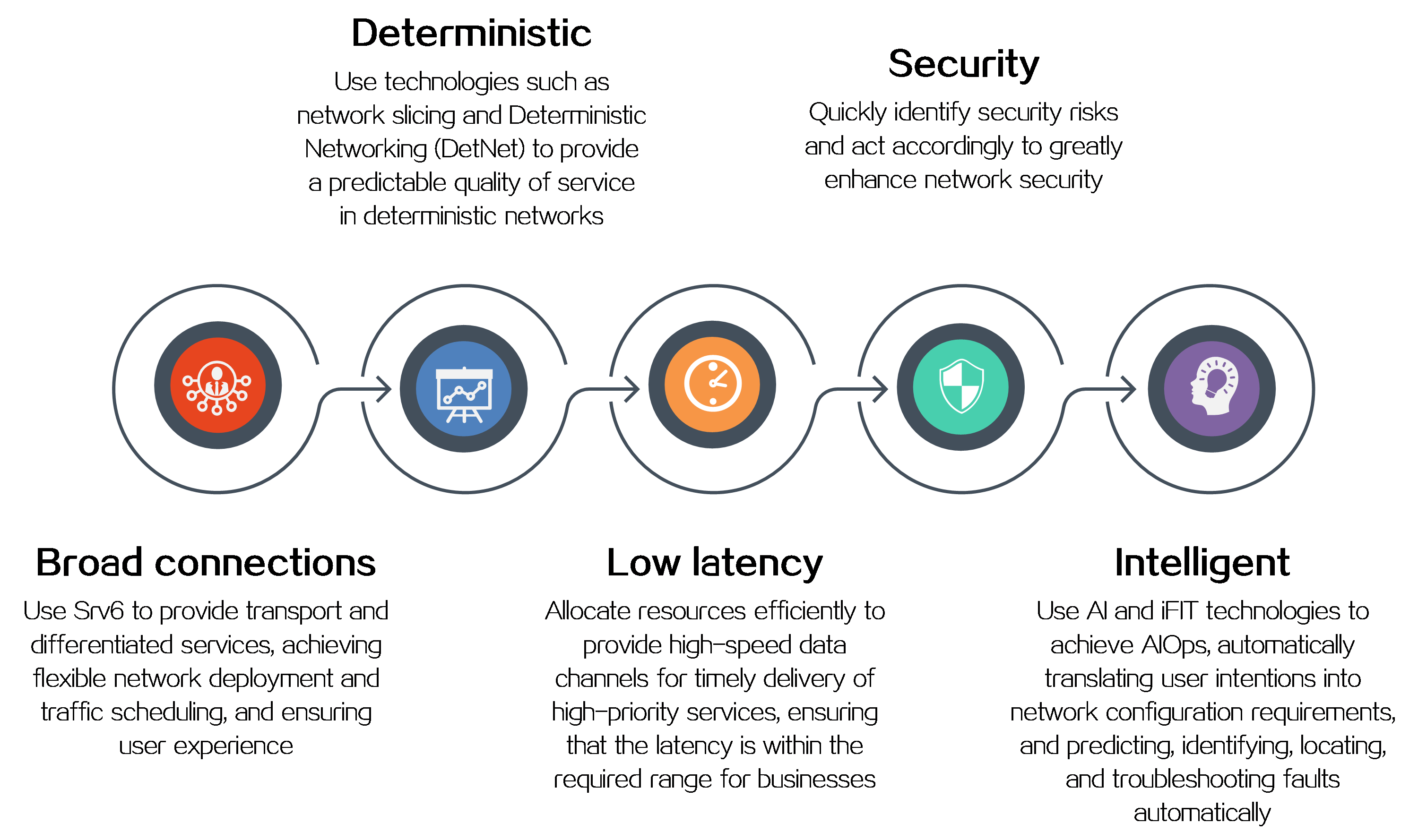
IPv6+ not only provides a large address space and flexible expansion but also enhances the capabilities of IP networks in the following aspects as shown in Figure2 .
Figure2 IPv6+ technical benefits
3 Technical advancement roadmap
Figure3 IPv6+ technical advancement roadmap
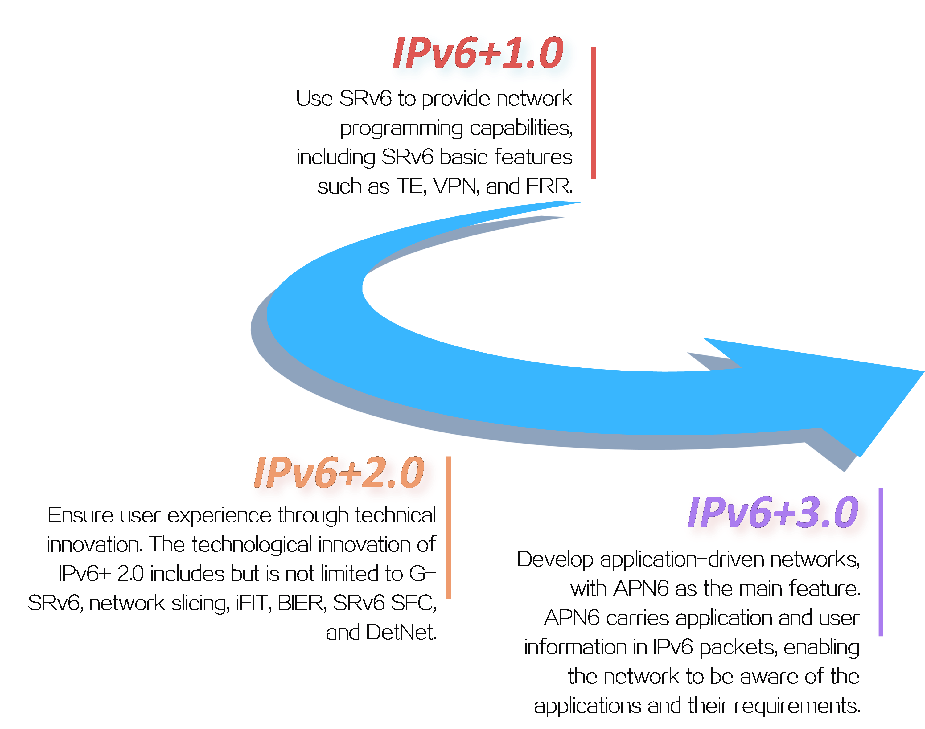
H3C has basically implemented IPv6+ 1.0, IPv6+ 2.0, and IPv6+ 3.0, and is closely following the development trend of IPv6+ technology for continuous evolution. With IPv6+ technology, H3C can help customers address the challenges of future network technologies, ensuring efficient, secure, and smooth network communication. At the same time, H3C will continue to be committed to the development and popularization of IPv6+ technology to meet the customers’ changing needs and help drive digital transformation of enterprises.
4 Key technologies
|
|
4.1 SRv6 overview
About SRv6
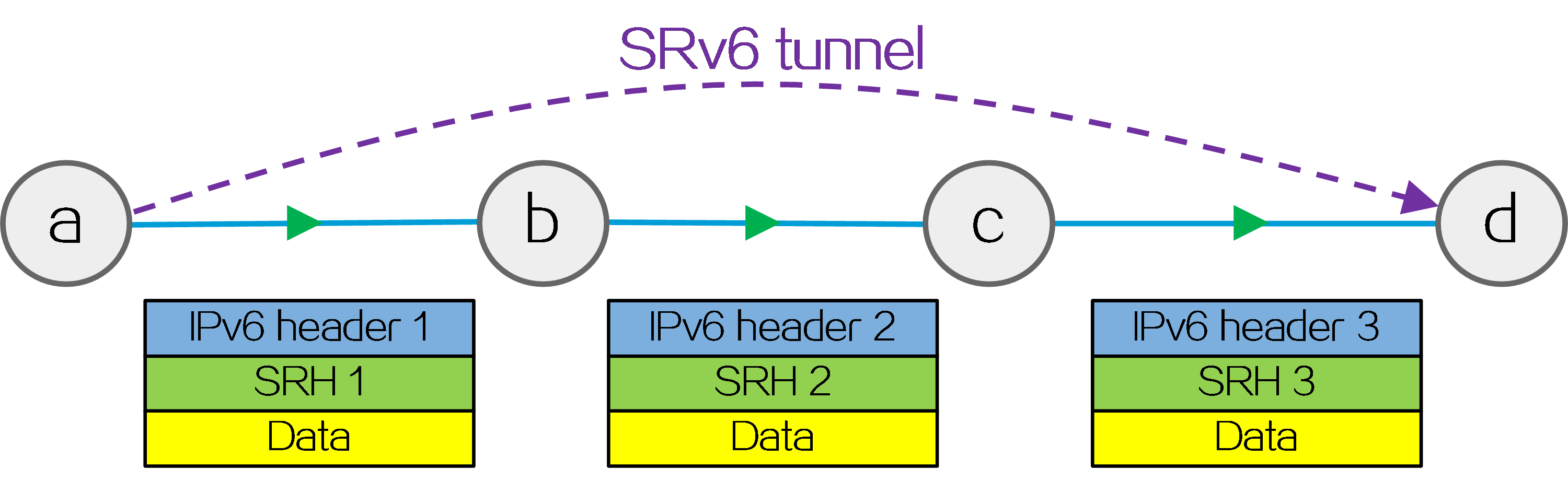
Segment Routing (SR) is a source routing technology. The source node selects a path for packet forwarding, and then encodes the path in the packet header as an ordered list of segments. Each segment is identified by the Segment Identifier (SID). The SR nodes along the path forward the packets based on the SIDs in the packets. Only the source node needs to maintain the path status.
IPv6 SR (SRv6) uses IPv6 addresses as SIDs to forward packets.
Figure4 SRv6 tunnel
Benefits
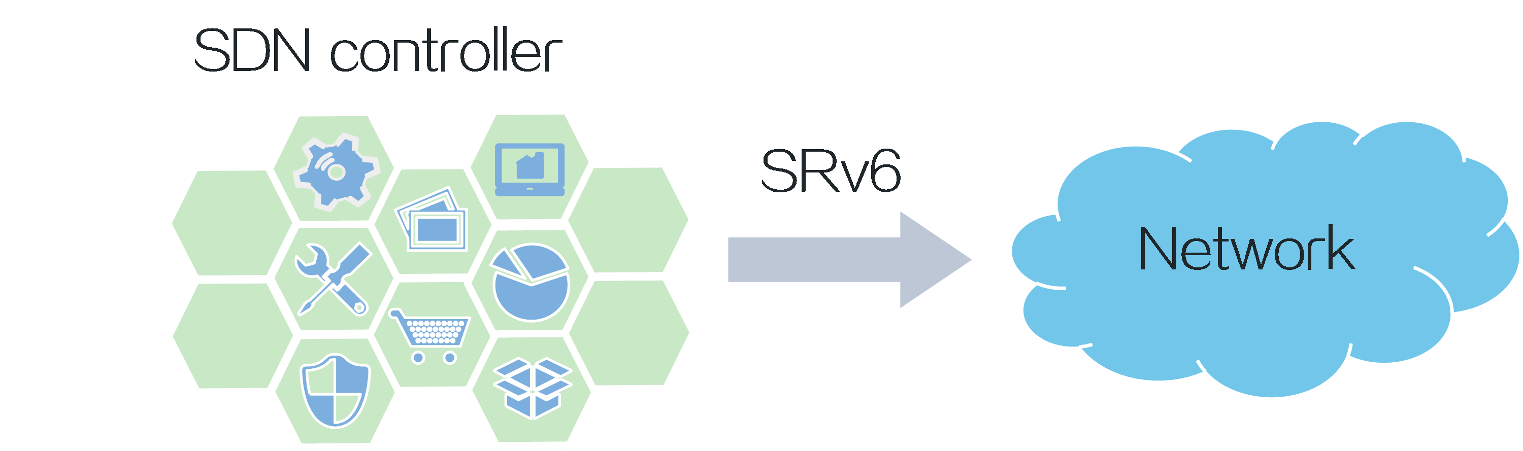
Smart control
SRv6, designed based on the SDN architecture, bridges the gap between applications and networks, enabling application-driven networking. In SRv6, forwarding paths, forwarding behaviors, and service types are all controllable.
Figure5 SRv6 architecture
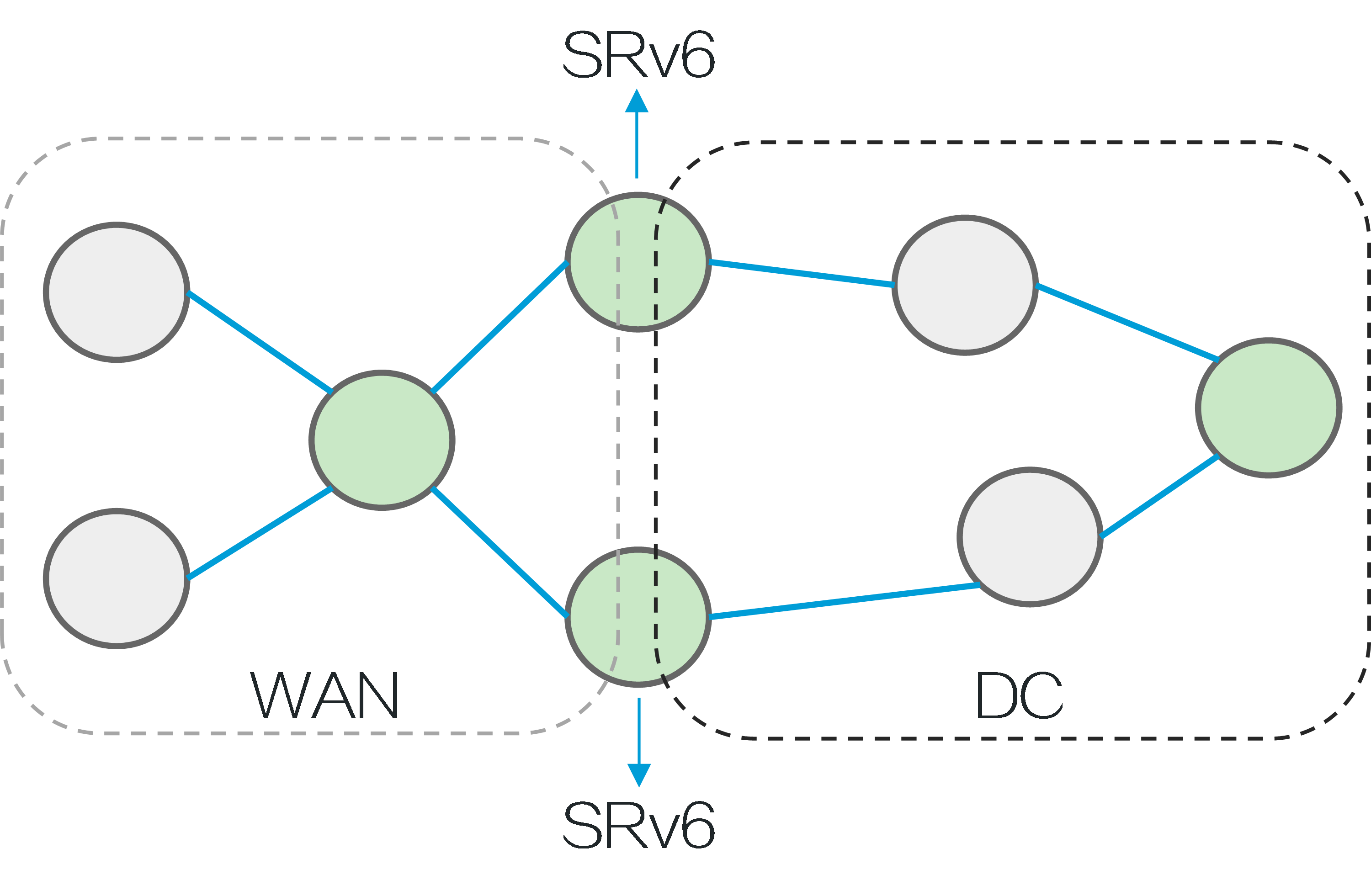
Easy deployment
SRv6 is implemented based on IGP and BGP extensions, eliminating the need for MPLS labels and label distribution protocols, simplifying configuration.
In an SRv6 network, new services can be deployed without the need to upgrade a large number of network devices. For example, in data centers and WANs, new services can be deployed as long as the edge devices and specific network nodes support SRv6 and the other devices support IPv6.
Figure6 SRv6 deployment
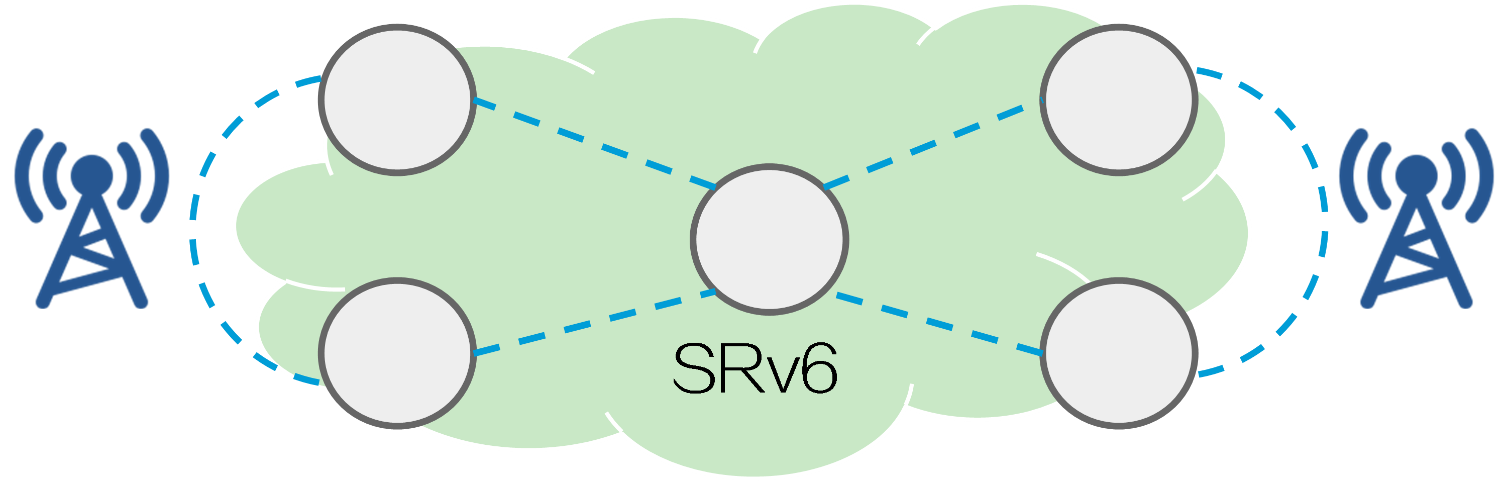
Adaptive to 5G services
With the development of 5G services, IPv4 addresses are no longer sufficient to meet the network requirements of service providers. You can deploy SRv6 in service provider networks to enable all devices to forward traffic through IPv6 addresses, addressing the requirements of 5G services.
Figure7 Deploying SRv6 on service provider networks
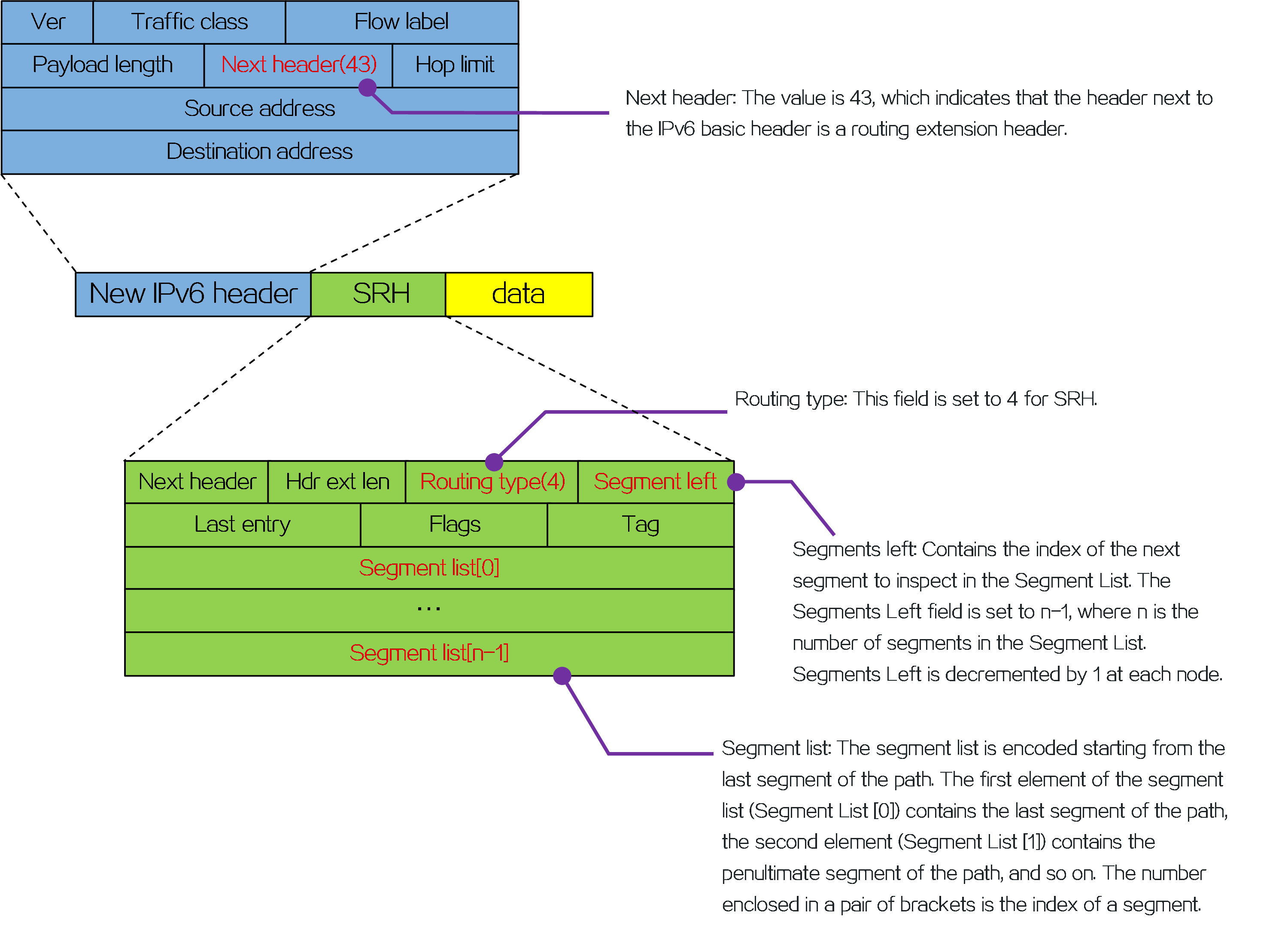
Packet encapsulation
An outer IPv6 header and a Segment Routing Header (SRH) are added to the original data packet to form an SRv6 packet.
Figure8 SRv6 packet encapsulation
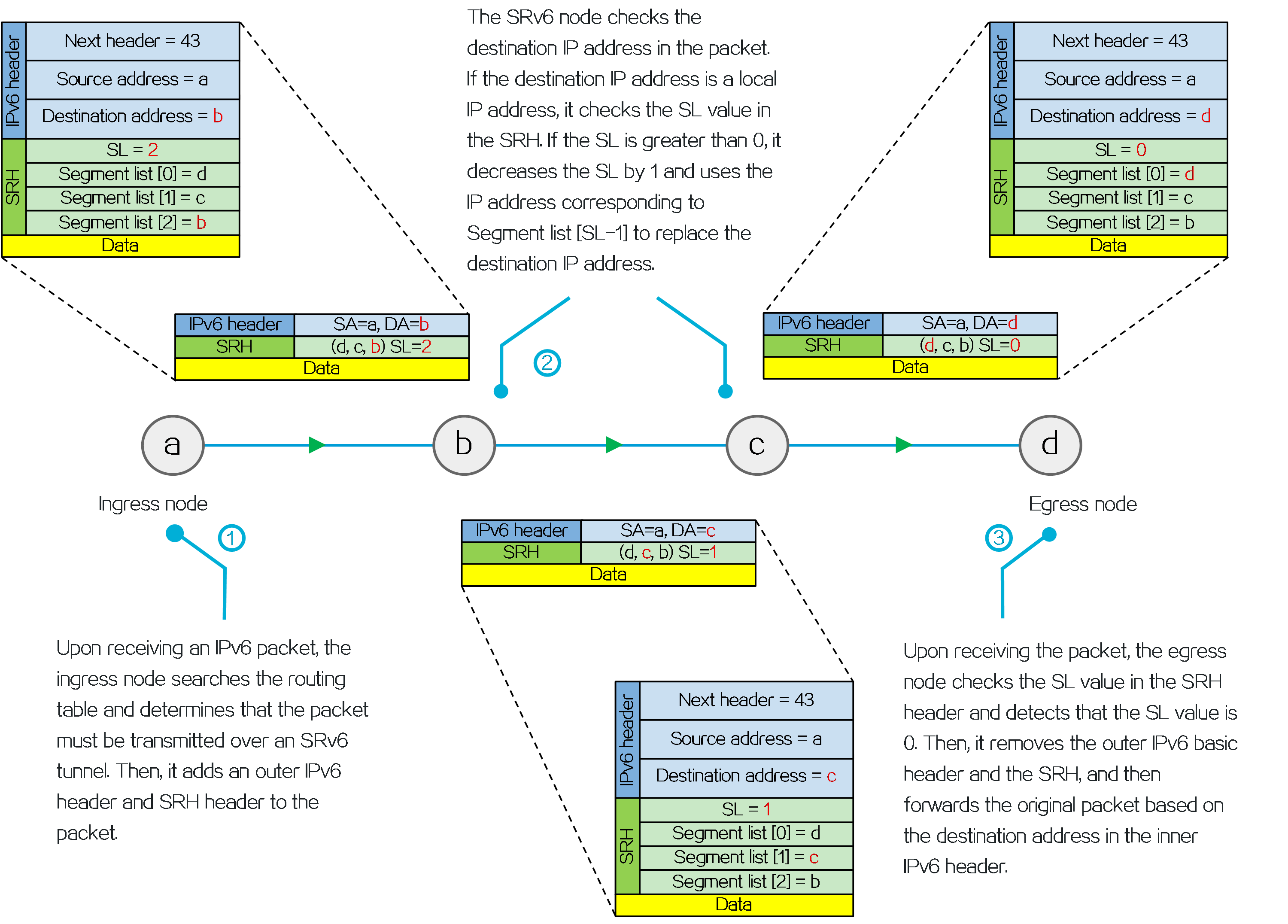
Operating mechanism
Figure9 SRv6 operating mechanism
4.2 SRv6 TE Policy
About SRv6 TE policy
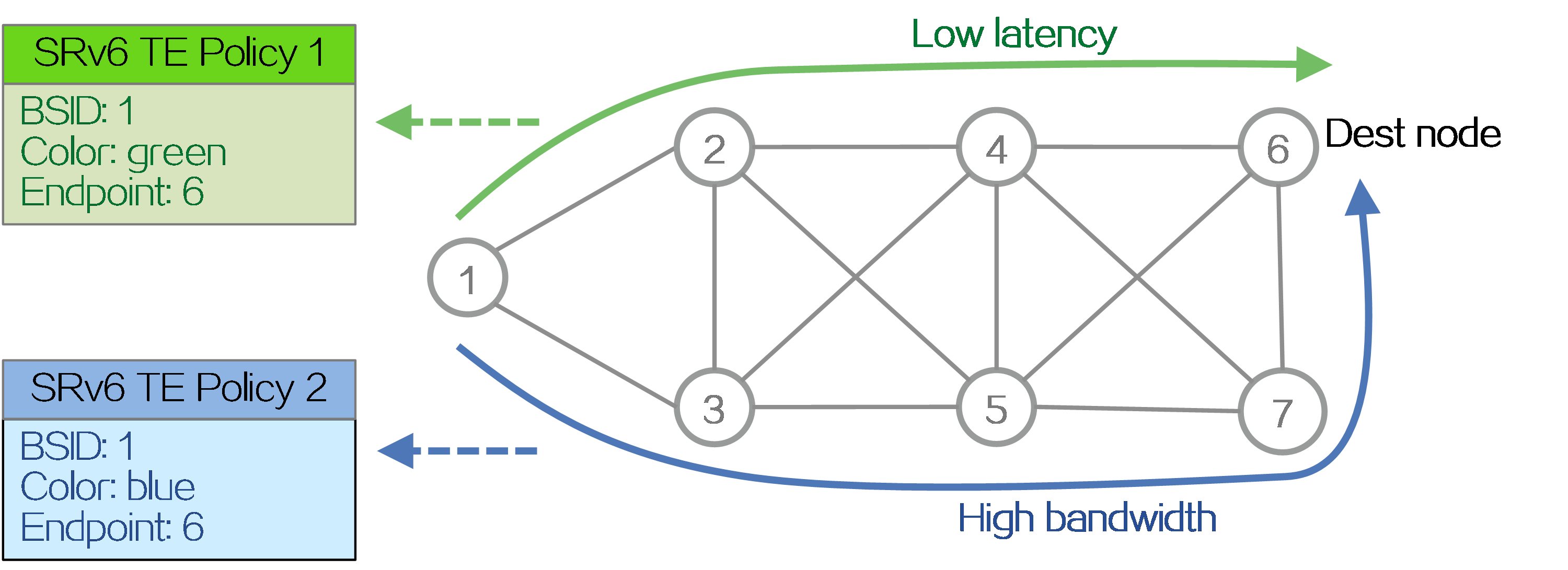
An SRv6 TE policy is a flexible forwarding policy that allows for the selection of appropriate forwarding paths based on service requirements. An SRv6 TE policy consists of multiple forwarding paths, which can be used for load balancing and backup between the paths.
An SRv6 TE policy can be identified through the following sections:
· BSID—SID of the ingress node (source node), used to steer the traffic to the forwarding path in the SRv6 TE policy.
· Color—Color attribute for the SRv6 TE policy, used to distinguish an SRv6 TE policy from other SRv6 TE policies that are configured for the same source and destination nodes. Color attributes can represent different quality of service requirements, such as low latency, high bandwidth, etc. Administrators can assign different color attributes to different SRv6 TE policies based on service types.
· Endpoint—IPv6 address of the destination node.
Figure10 SRv6 TE policy forwarding paths
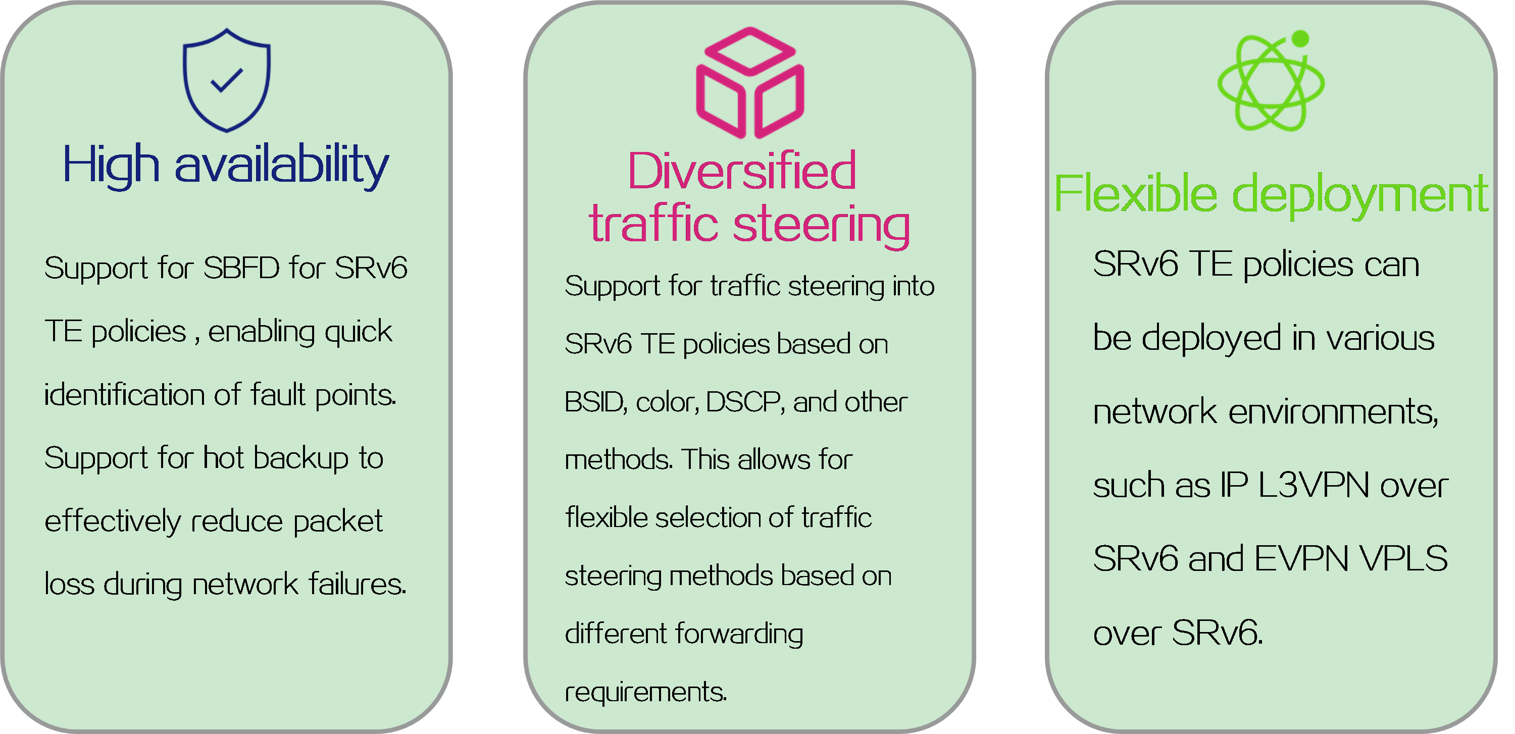
Technical benefits
Figure11 Technical benefits of SRv6 TE policy
Network model
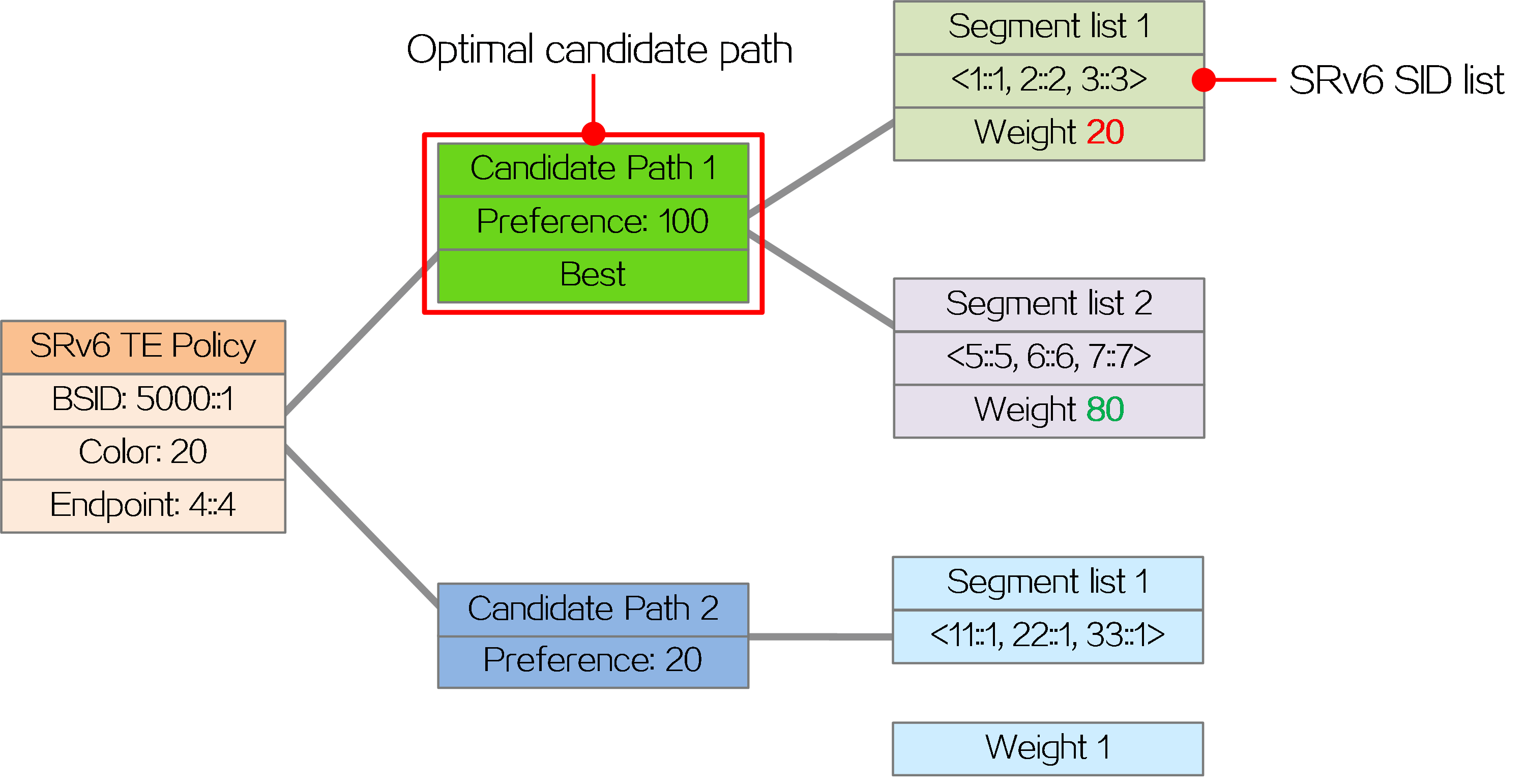
An SRv6 TE policy can contain multiple candidate paths. A candidate path can contain multiple segment lists (SID lists), and each segment list carries a weight attribute.
· Candidate paths
Candidate paths carry preference attributes, and the preferences of different candidate paths are different. When forwarding traffic through an SRv6 TE policy, the device selects the candidate path with the highest preference (called the optimal candidate path) from multiple valid candidate paths for packet forwarding.
· SID lists
A SID list is a list of SIDs that indicates a packet forwarding path.
As shown in the figure below, the SRv6 TE policy includes two candidate paths, Candidate Path 1 and Candidate Path 2. Candidate Path 1 has the highest preference, so the SRv6 TE policy uses candidate path 1 to forward packets. Candidate Path 1 contains two SID lists, Segment List 1 and Segment List 2. Segment List 1 contains SRv6 SIDs <1::1, 2::2, 3::3> with a weight of 20. Segment List 2 contains SRv6 SIDs <5::5, 6::6, 7::7> with a weight of 80.
Figure12 Network model of SRv6 TE policy
Steering methods
SRv6 TE policy steering refers to the process of matching certain packet characteristics or routing rules to direct packets to an SRv6 TE policy for forwarding.
Table1 SRv6 TE policy steering methods and rules
|
Steering method |
Steering rule |
|
BSID-based traffic steering |
If the destination IPv6 address of a received packet is the BSID of an SRv6 TE policy, the device uses the SRv6 TE policy to forward the packet. |
|
Color-based traffic steering |
If the matching BGP route of a packet carries a color extended community attribute and nexthop address that match the color attribute and endpoint address of an SRv6 TE policy, the device forwards the packet through that SRv6 TE policy. |
|
DSCP-based traffic steering |
The device identifies the color value mapped to the DSCP value of a packet, and searches for the SRv6 TE policy containing that color value. If a matching SRv6 TE policy is found, the device forwards the packet through that SRv6 TE policy. |
|
Tunnel policy-based traffic steering |
In L2VPN and L3VPN networks, tunnel policies are deployed to specify SRv6 TE policies as the public network tunnels to forward private network packets. |
Path selection
The path selection principles for different steering methods are the same. After data packets are steered into an SRv6 TE policy, the SRv6 TE policy selects a forwarding path for the packets as follows:
(1) Selects the candidate path that has the highest preference among all valid candidate paths.
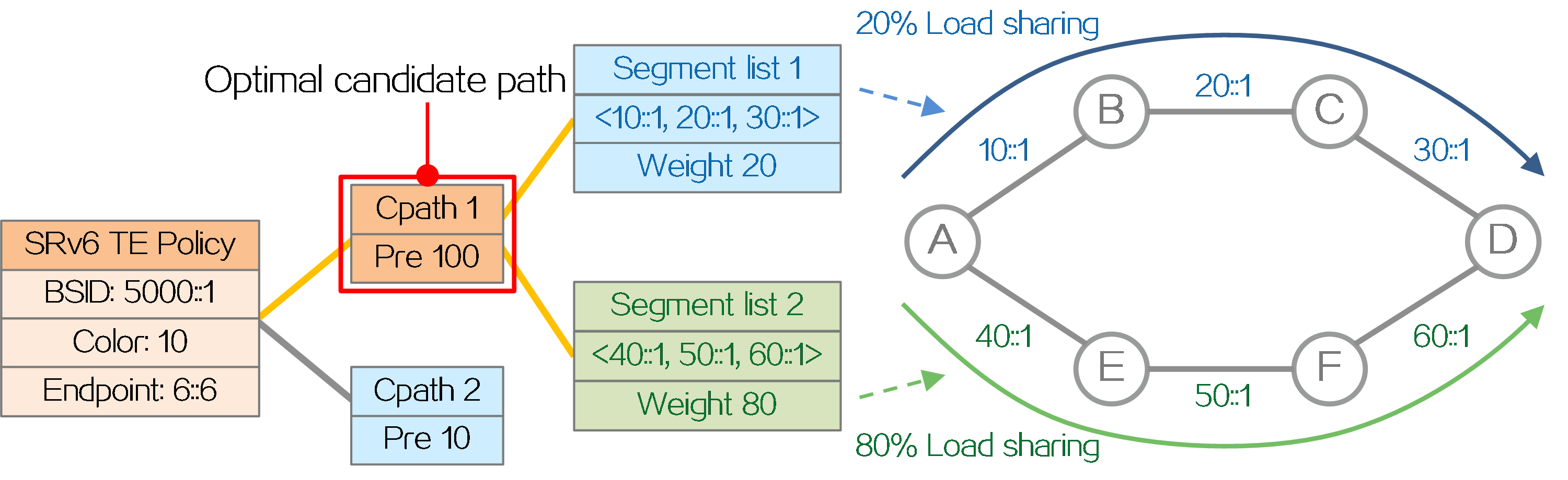
(2) Performs Weighted ECMP (WECMP) load sharing among the SID lists of the selected candidate path. Assume there are n valid SID lists in the candidate path, and the weight of SID list x is Wight x. The load of SID list x is equal to Weight x/(Weight 1 + Weight 2 + … + Weight n).
As shown in the figure below, the SRv6 TE policy selects the candidate path with the highest preference, Candidate Path 1, to forward traffic. Candidate Path 1 contains two SID lists, Segment List 1 and Segment List 2. Segment List 1 contains SRv6 SIDs <10::1, 20::1, 30::1> with a weight of 20. Segment List 2 contains SRv6 SIDs <40::1, 50::1, 60::1> with a weight of 80. The traffic is load balanced between Segment List 1 and Segment List 2 based on weight. The total weight of Segment List 1 and Segment List 2 is 100, so the traffic proportion shared by Segment List 1 is 20÷100=20%, and the traffic proportion shared by Segment List 2 is 80÷100=80%.
Figure13 SRv6 TE policy path selection
BSID stitching
SRv6 over SRv6
The supported SID depth of the device is limited. When the source node of an SRv6 TE policy encapsulates the packet with SRH, the number of SIDs cannot exceed the limit supported by the device. In order to reduce the number of SIDs in the SID list of an SRv6 TE policy, the SID list supports inserting a BSID, which represents the SID list of a candidate path for another SRv6 TE policy. Based on the BSID, the traffic is redirected to another candidate path of an SRv6 TE policy. This capability is called BSID stitching.
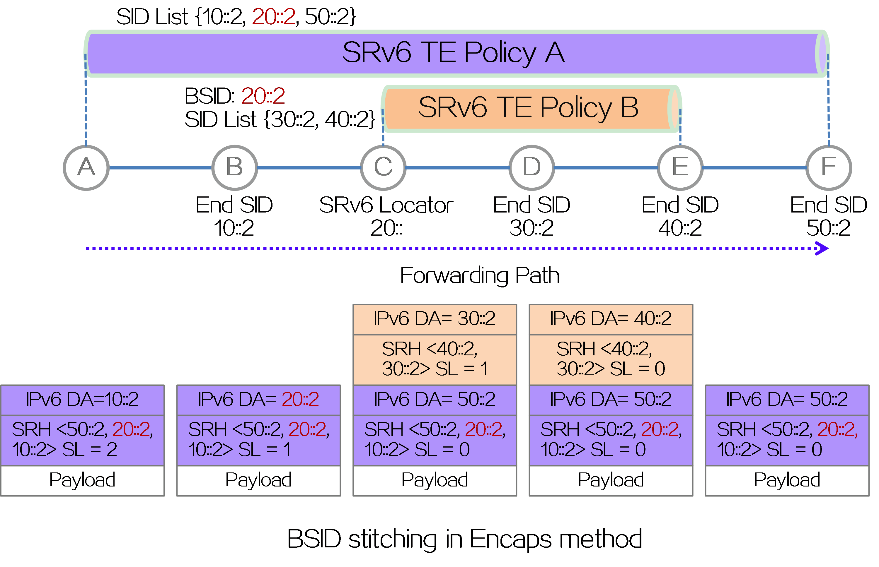
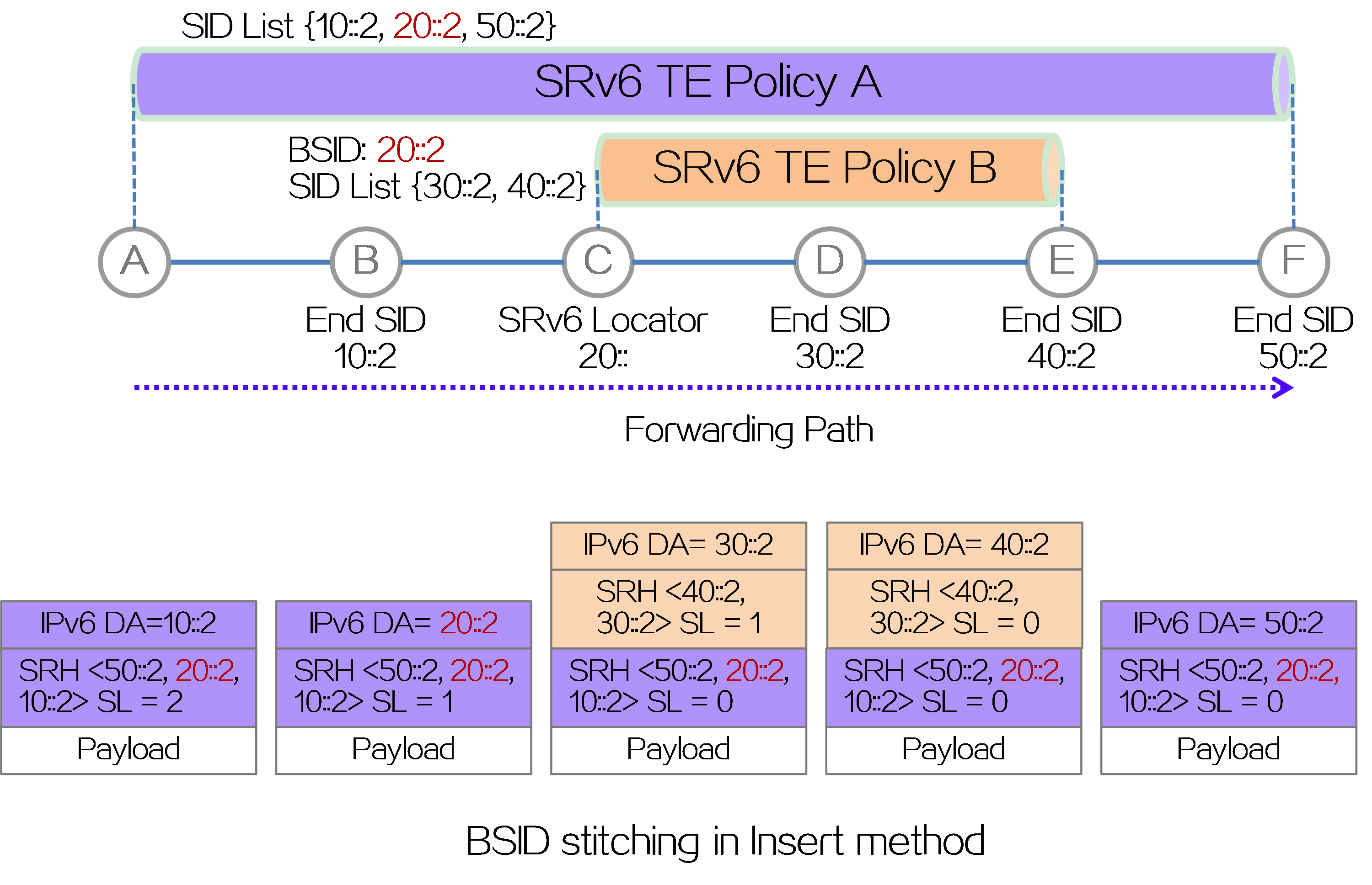
As shown in the figure below, BSID stitching supports the Encaps method of encapsulating an IPv6 basic header and SRH extension header outside the original packet, and also supports the Insert method of inserting a new SRH extension header after the IPv6 basic header of the original packet.
· Encaps method: The BSID of SRv6 TE Policy B is inserted into the SID list of SRv6 TE Policy A. When a packet is forwarded to node C through SRv6 TE Policy A, the source node C of SRv6 TE Policy B discovers that the BSID is a local SID of End.B6ENCAPS type. Therefore, it executes the forwarding instruction of the BSID, which is to add an IPv6 header and SRH outside the packet, with SRH containing the SID list of SRv6 TE Policy B.
Figure14 BSID stitching in Encaps method
· Insert method: The BSID of SRv6 TE policy B is inserted into the SID list of SRv6 TE Policy A. When the packet is forwarded to node C through SRv6 TE Policy A, the source node C of SRv6 TE Policy B discovers that the BSID is a local SID of End.B6INSERT type. Therefore, it executes the forwarding instruction of the BSID, which is to insert the SRH after the original IPv6 packet header, with SRH containing the SID list of SRv6 TE Policy B.
Figure15 BSID splicing in Insert method
SRv6 over SR-MPLS
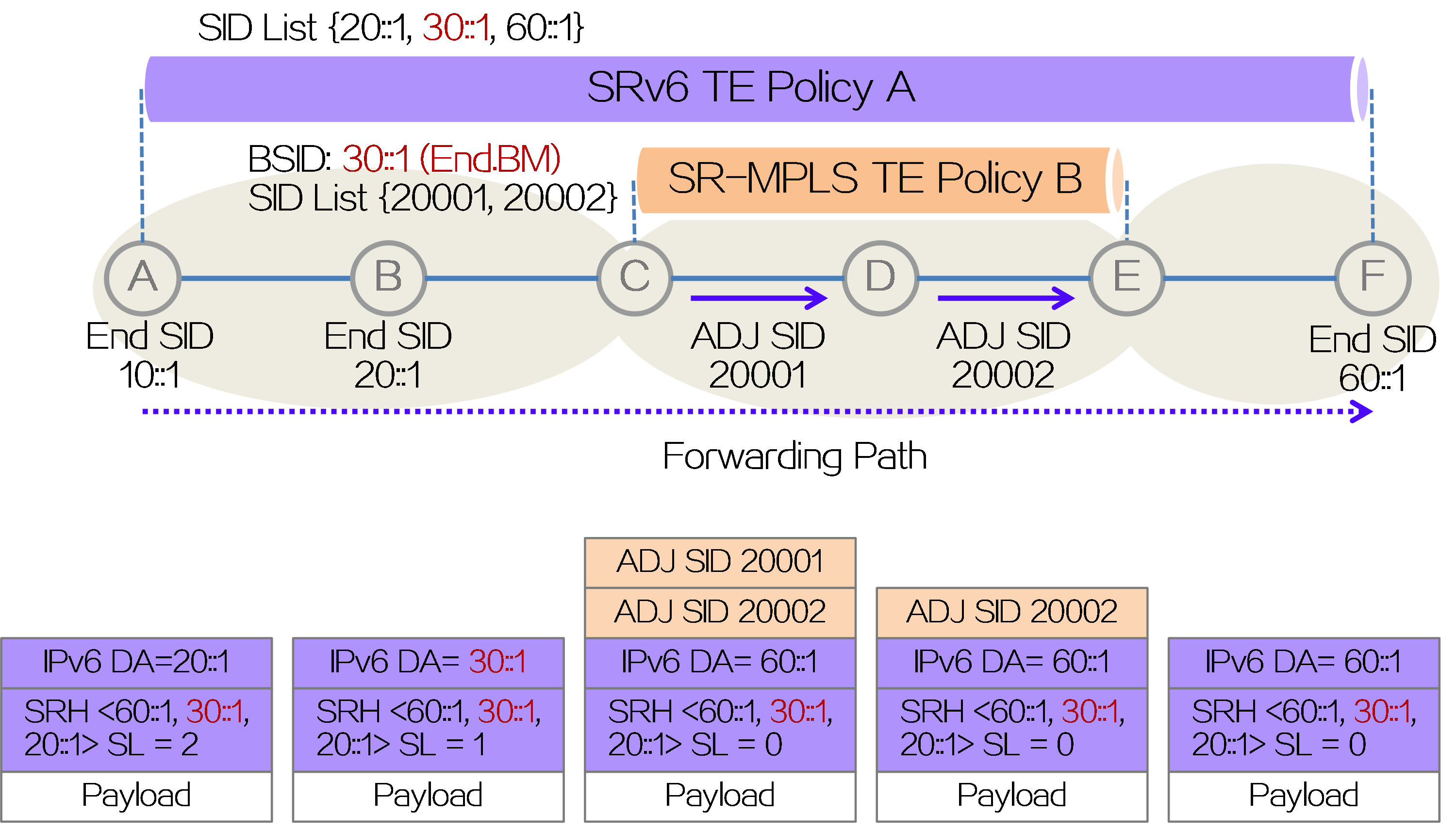
The BSID stitching feature can not only reduce the number of SIDs in the SID list, but also achieve SRv6 and SR-MPLS interworking. In the SRv6 and SR-MPLS interworking scenario, packets traverse multiple SRv6 and SR-MPLS domains via SRv6 TE policy tunnels to achieve end-to-end service interoperability. This scenario is referred to as SRv6 over SR-MPLS.
As shown in the figure below, a new type of SRv6 SID called End.BM is defined in the SRv6 over SR-MPLS scenario as the BSID for SR-MPLS TE Policy B. When configuring SRv6 TE Policy A, insert BSID 30::1 of the End.BM type into the SID list of SRv6 TE Policy A. BSID 30::1 represents the SID list of the optimal candidate path for SR-MPLS TE Policy B, which is the MPLS label stack {20001, 20002}. When an IPv6 packet is forwarded to the source node C of SR-MPLS TE Policy B, the node performs the function of End.BM SID, that is, encapsulating the MPLS label stack {20001, 20002} of SR-MPLS TE Policy B outside the IPv6 packet. Node C forwards the packet in the SR-MPLS domain based on the MPLS label stack encapsulated in the packet. After popping all MPLS labels at the tail node E of SR-MPLS TE Policy B, it continues to forward the packet as an SRv6 packet. By stitching the BSID of type End.BM into the SID list of the SRv6 TE policy, the interworking between SRv6 and SR-MPLS is achieved.
Figure16 BSID stitching in SRv6 over SR-MPLS scenario
Configuration examples
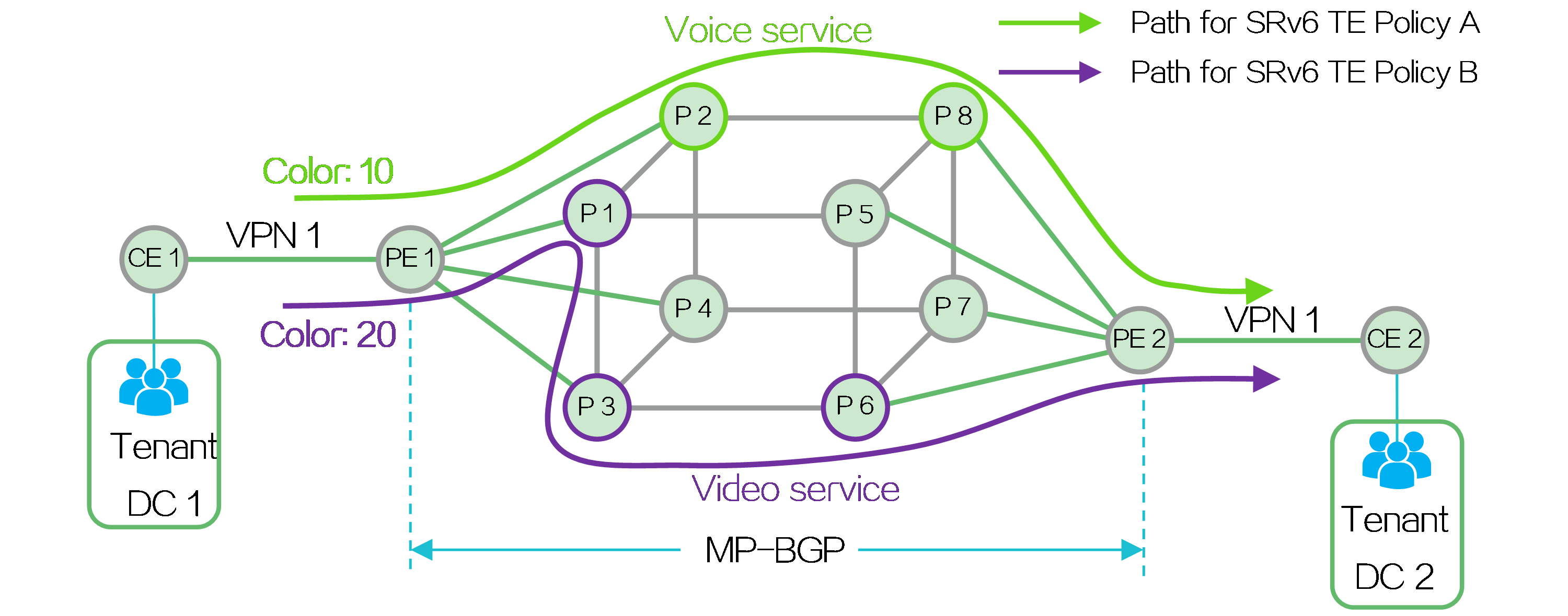
By deploying L2VPN/L3VPN over SRv6 TE policy, tenants within the same VPN located in different data centers (DCs) can communicate with each other. The source node can flexibly plan and allocate the forwarding paths for different service traffic, so as to meet the various service requirements of the tenants. Taking IP L3VPN over SRv6 TE policy as an example, the deployment mechanism of this solution is implemented as follows:
· Create VPN 1 on PE 1 and PE 2 to allow the users of the same tenant located in different data centers to join the same VPN. Deploy MP-BGP between PEs to transmit private network routing information for achieving Layer 3 connectivity.
· Deploy SRv6 TE policies with different color attributes between PE 1 and PE 2, select forwarding paths based on the tenant's service requirements, and steer the traffic of a service into the corresponding SRv6 TE policy.
Figure17 Typical application of SRv6 TE policies
4.3 SRv6 VPN overview
About SRv6 VPN
With the development of 5G services, IPv4 addresses can no longer meet the network needs of operators, and the construction of IPv6 networks has been put on the agenda by operators. Deploying SRv6 VPN in the operator's IPv6 network and using SRv6 to support VPN services in the network enable better fulfillment of 5G service requirements.
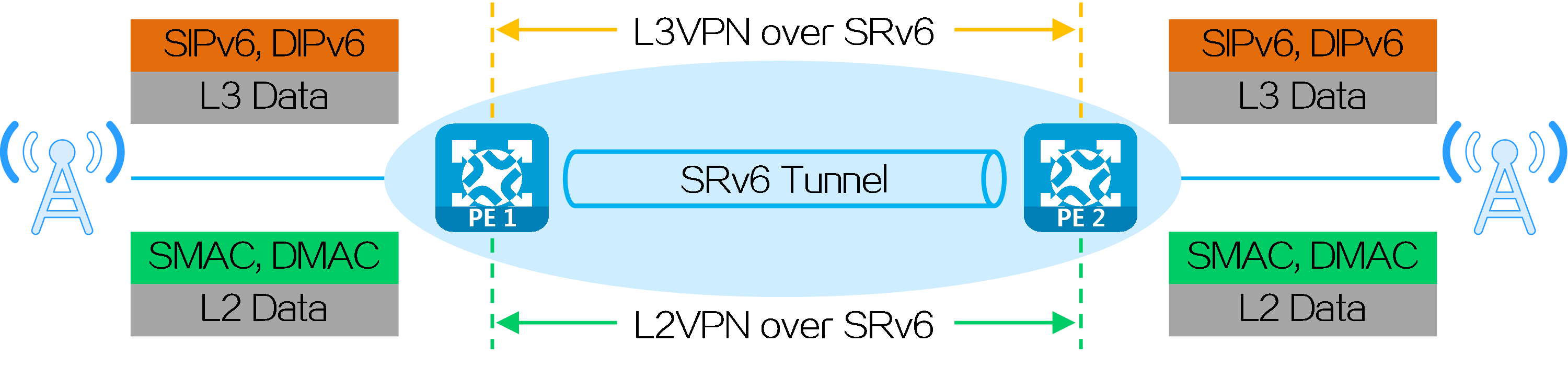
According to the types of VPN services, SRv6 VPN services can be divided into the following types:
· L3VPN services—Transparently transmit user Layer 3 service packets through the IPv6 backbone network. L3VPN services include IP L3VPN over SRv6 and EVPN L3VPN over SRv6.
· L2VPN services—Transparently transmit user Layer 2 service packets through the IPv6 backbone network. L2VPN services include EVPN VPWS over SRv6 and EVPN VPLS over SRv6.
Figure18 SRv6 VPN service classification
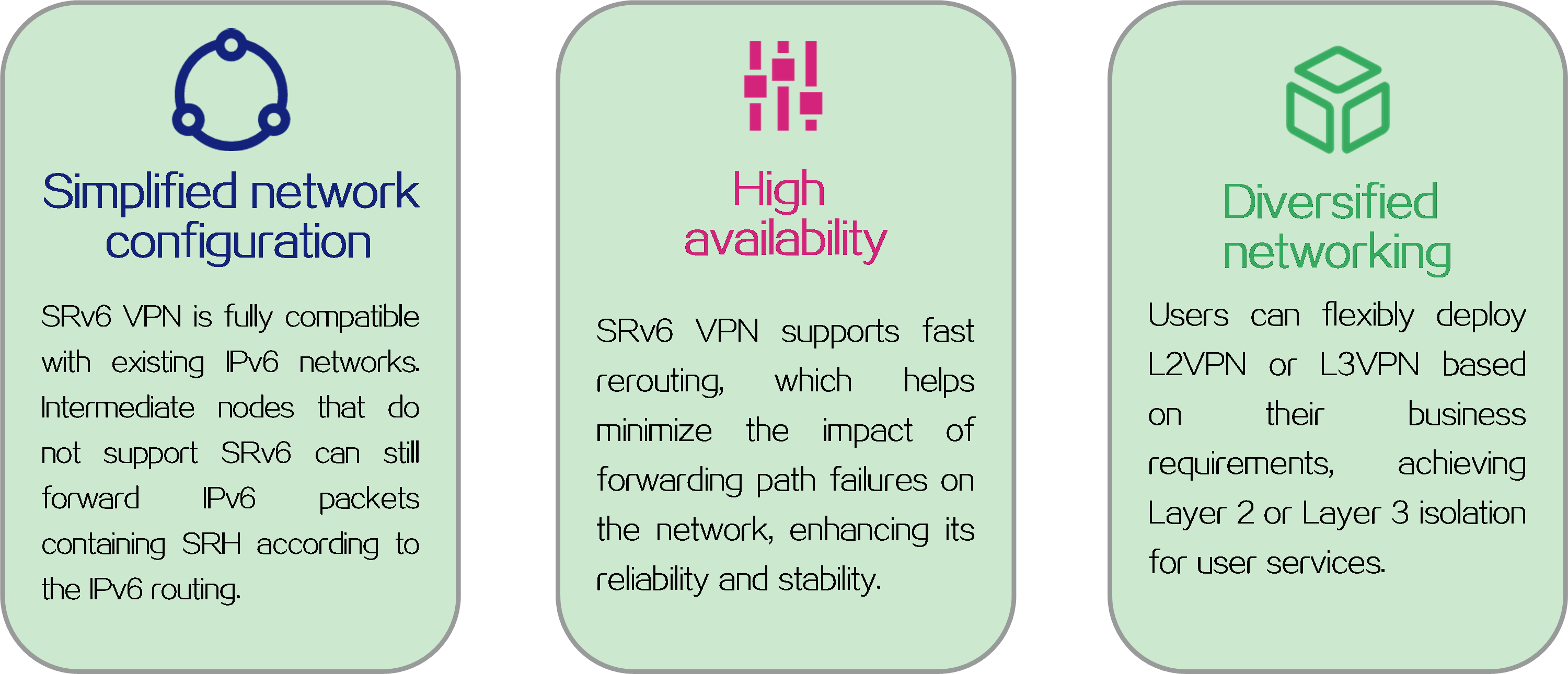
SRv6 VPN advantages
Figure19 SRv6 VPN advantages
L3VPN over SRv6 operating mechanism
Networking model
In IP L3VPN over SRv6 or EVPN L3VPN over SRv6 networking environment, private network route information is advertised between PEs through MP-BGP, and packets are forwarded through SRv6 encapsulation. When the physical sites of users are dispersed in different locations, the existing service providers or enterprise IPv6 networks can be used to provide Layer 3 interconnection for users of the same VPN in different sites, while ensuring isolation between users of different VPNs.
Figure20 L3VPN over SRv6 networking model
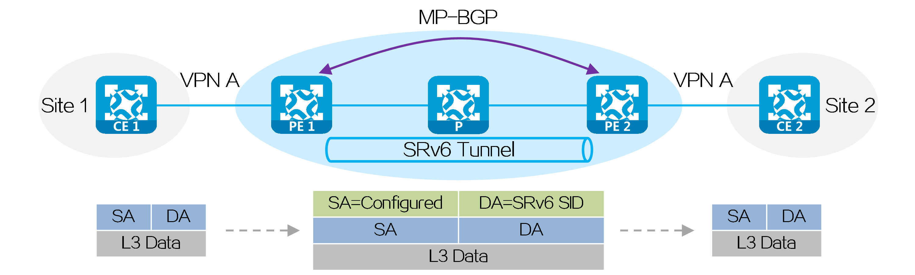
Route advertisement
Taking CE 1 as an example, a private network route of CE 1 is advertised to CE 2 through MP-BGP as follows:
(1) CE 1 uses IGP or BGP to advertise the private network route of the local site to PE 1.
(2) After learning private network routing information from CE 1, PE 1 assigns an SRv6 SID to the private network route and forms a VPN route. PE 1 uses MP-BGP to advertise the VPN route with the SRv6 SID to PE 2.
(3) After PE 2 receives the VPN route, it adds the VPN route to the VPN routing table, converts the VPN route into a private network route, and then advertises the private network route to CE 2.
(4) After CE 2 receives the route, it learns the route into the routing table. In this way, CE 2 has learned the route of CE 1.
Packet forwarding
After route advertisement is completed, a packet can be sent from CE 2 to CE 1 as follows:
(1) CE 2 sends the packet to PE 2.
(2) After receiving the private network packet, PE 2 looks up the matching route for the destination address in the VPN routing table. It finds the SRv6 SID assigned by PE 1 to the private network route.
(3) PE 2 encapsulates an outer IPv6 header for the packet, with the destination IPv6 address being the identified SRv6 SID, and the source IPv6 address can be configured as needed.
(4) According to the SRv6 SID, PE 2 looks up the IPv6 routing table and forwards the packet to P via the optimal IGP route.
(5) After receiving the packet, P looks up the IPv6 routing table according to the SRv6 SID and forwards the packet to PE 1 via the optimal IGP route.
(6) After receiving the packet, PE 1 performs the function of the SRv6 SID, that is, it decapsulates the packet to remove the outer IPv6 header and looks up the private network route in the routing table of the specified VPN based on the SRv6 SID, and then sends the packet to CE 1.
|
|
L2VPN over SRv6 operating mechanism
Networking model
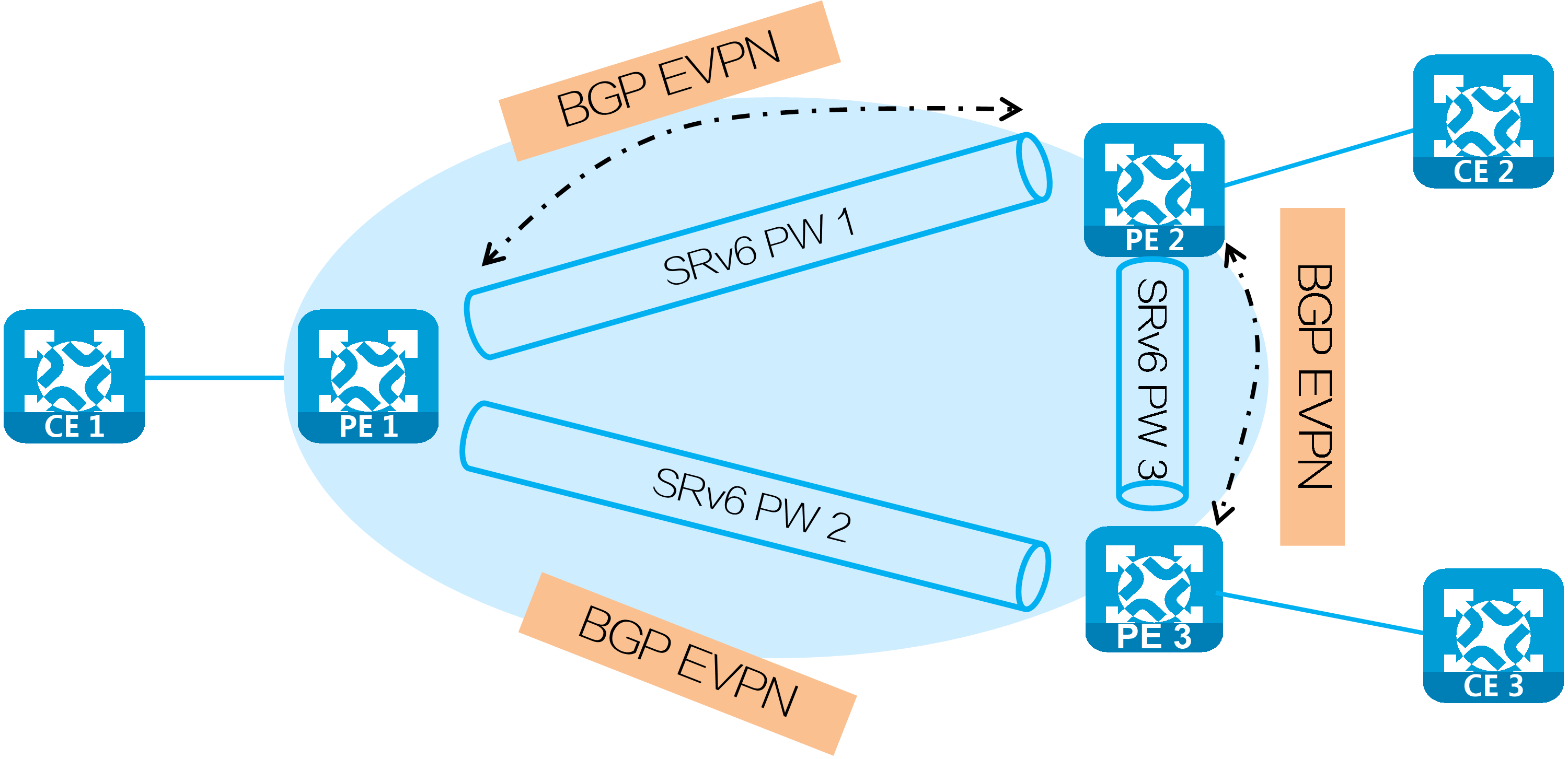
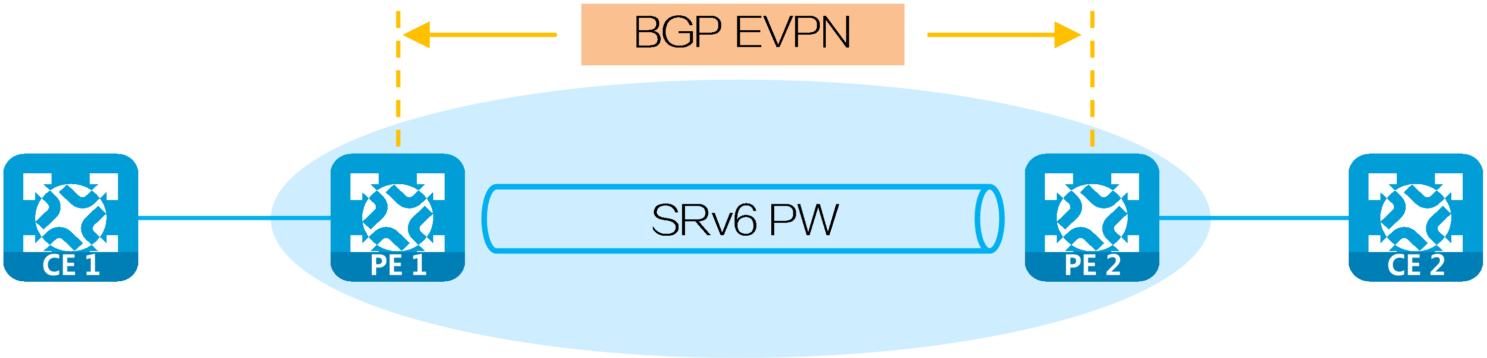
In the networking environment of EVPN VPWS over SRv6 and EVPN VPLS over SRv6, PEs establish SRv6 tunnels by advertising SRv6 SIDs in BGP EVPN routes. Two SRv6 tunnels in opposite directions between PEs form a PW, which encapsulates and forwards Layer 2 data packets between site networks, enabling transparent transmission of Layer 2 data for users over the IPv6 backbone network.
Figure21 L2VPN over SRv6 networking model
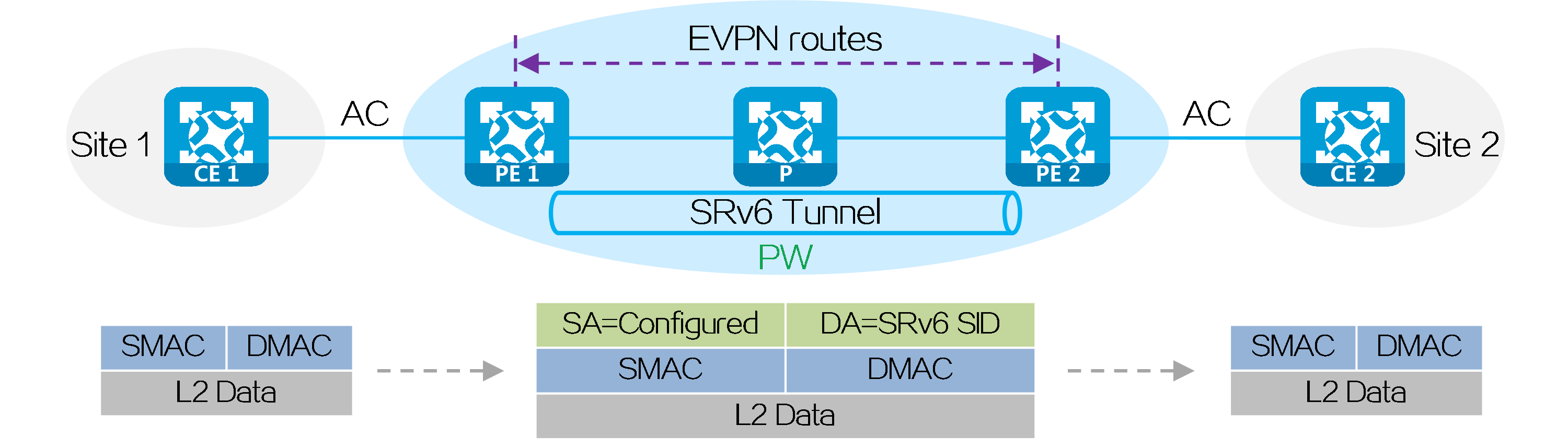
An Attachment Circuit (AC) is a physical or virtual circuit that connects CE and PE.
A pseudowire (PW) is a virtual bidirectional connection between two PE devices.
Establishing a PW
The process of establishing a PW between PEs through BGP EVPN routing is as follows:
(1) PE 1 and PE 2 mutually advertise BGP EVPN routes, carrying the SRv6 SID assigned to the local end as a cross-connect or VSI in the BGP EVPN route.
(2) PE 1 and PE 2 establish a single-hop SRv6 tunnel from the local PE to the remote PE after receiving the BGP EVPN route. The SID identifier of this tunnel is the SRv6 SID in the route.
(3) After establishing a single-hop SRv6 tunnel between PE 1 and PE 2 in both directions, the two SRv6 tunnels form a PW to carry user Layer 2 data. The PW is called an SRv6 PW.
Packet forwarding
After the BGP EVPN route advertisement is completed, a Layer 2 packet is sent from CE 1 to CE 2 as follows:
(1) CE 1 sends a Layer 2 packet to PE 1.
(2) After receiving the Layer 2 packet from the AC connected to CE 1, PE 1 performs the following:
· In EVPN VPWS over SRv6 networking, PE 1 identifies the SRv6 SID corresponding to the cross-connection associated with this AC.
· In the EVPN VPLS over SRv6 networking, PE 1 looks up the MAC address table within the VSI associated with this AC to find the corresponding SRv6 SID.
(3) PE 1 encapsulates an outer IPv6 header for the packet, with the destination IPv6 address being the identified SRv6 SID and the source IPv6 address being user-configured.
(4) After receiving the packet, PE 1 searches for the IPv6 routing table according to the SRv6 SID and forwards the packet to P through the optimal IGP route.
(5) After receiving the packet, P looks up the IPv6 routing table according to the SRv6 SID and forwards the packet to PE 2 via the optimal IGP route.
(6) PE 2 looks up the local SID table based on the SRv6 SID and performs the function of the SRv6 SID, which is to decapsulate the packet by removing the outer IPv6 header and forward it based on the SRv6 SID.
· In EVPN VPWS over SRv6 networking, PE 2 identifies the AC associated with the SRv6 SID and then forwards the packet through that AC to CE 2.
· In the EVPN VPLS over SRv6 networking, PE 2 identifies the VSI associated with the SRv6 SID, and then searches the MAC address table within that VSI to forward the packet to CE 2.
|
|
4.4 L3VPN over SRv6 BE
Introduction
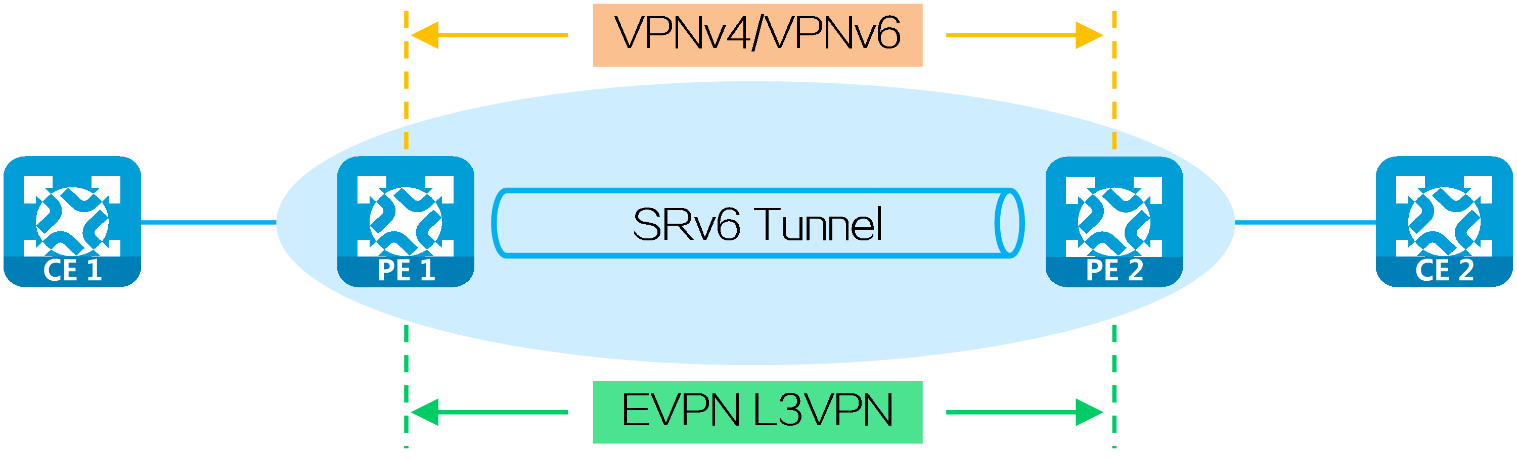
L3VPN over segment routing IPv6 best effort (SRv6 BE) carries IP L3VPN data in the public network over optimal SRv6 paths calculated with IGP, providing Layer 3 interconnections between users in the same VPN at different sites and implementing user isolation among different VPNs.
Based on the carried services in the network, L3VPN over SRv6 BE is classified into the following types:
· IP L3VPN over SRv6 BE—Transmits private network routes through VPNv4/VPNv6 routes between PEs to carry Layer 3 VPN services.
· EVPN L3VPN over SRv6 BE—Transmits private network routes through EVPN IP prefix routes between PEs to carry both Layer 2 and Layer 3 VPN services.
Figure22 L3VPN over SRv6 BE types
SRv6 SIDs
An L3VPN over SRv6 network uses the following types of SRv6 SIDs to identify private network packets.
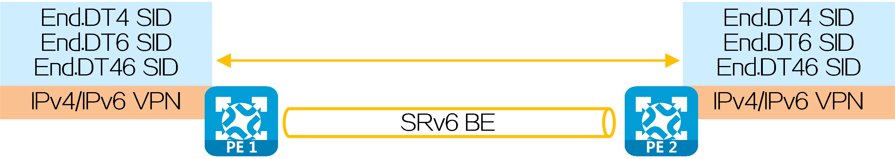
VPN instance-based SRv6 SID allocation
With VPN instance-based SRv6 SID allocation, a PE assigns an SRv6 SID to each VPN instance, and uses the SRv6 SID to identify the IPv4/IPv6 VPN in the network. Such SRv6 SIDs include End.DT4 SID/End.DT6 SID/End.DT46 SID:
· End.DT4 SIDs apply to the scenarios accessed by only IPv4 private network users.
· End.DT6 SIDs apply to the scenarios accessed by only IPv6 private network users.
· End.DT46 SIDs apply to the scenarios accessed by both IPv4 and IPv6 private network users.
Upon receiving a packet with an End.DT4 SID/End.DT6 SID/End.DT46 SID as the destination IPv6 address, a PE decapsulates the packet by removing its IPv6 packet header, obtains the VPN instance associated with the SID, and forwards the packet according to routing table lookup in the VPN instance.
Figure23 VPN instance-based SRv6 SID allocation
Next hop-based SRv6 SID allocation
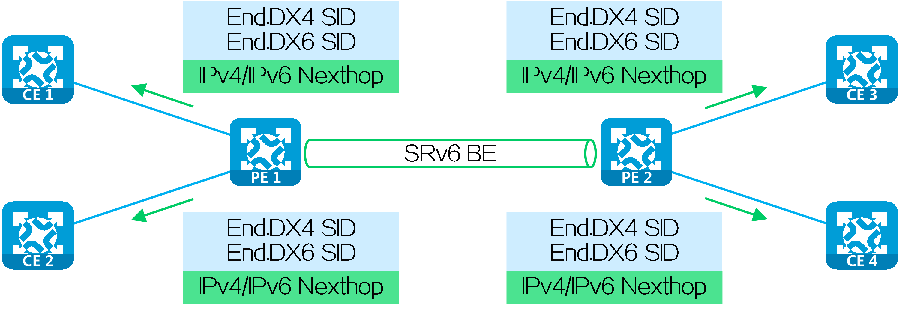
With next hop-based SRv6 SID allocation, a PE assigns an SRv6 SID to each next hop, and uses the SRv6 SID to identify the IPv4/IPv6 next hop in the network. Such SRv6 SIDs include End.DX4 SID/End.DX6 SID:
· End.DX4 SIDs apply to the scenarios accessed by only IPv4 private network users.
· End.DX6 SIDs apply to the scenarios accessed by only IPv6 private network users.
Upon receiving a packet with an End.DX4 SID/End.DX6 SID as the destination IPv6 address, the device decapsulates the packet by removing its IPv6 packet header, and forwards the packet based on the SID-associated next hop and output interface to the specified device in the private network.
Figure24 Next hop-based SRv6 SID allocation
Operating mechanism
The route advertisement and packet forwarding processes of IP L3VPN over SRv6 is similar to those of EVPN L3VPN over SRv6. This section uses IPv4 L3VPN over SRv6 BE to illustrate the process.
Route advertisement
The route advertisement process based on End.DT4 SID/End.DT6 SID/End.DT46 SID is similar to that based on End.DX4 SID/End.DX6 SID. This section uses End.DT4 SID to illustrate the process.
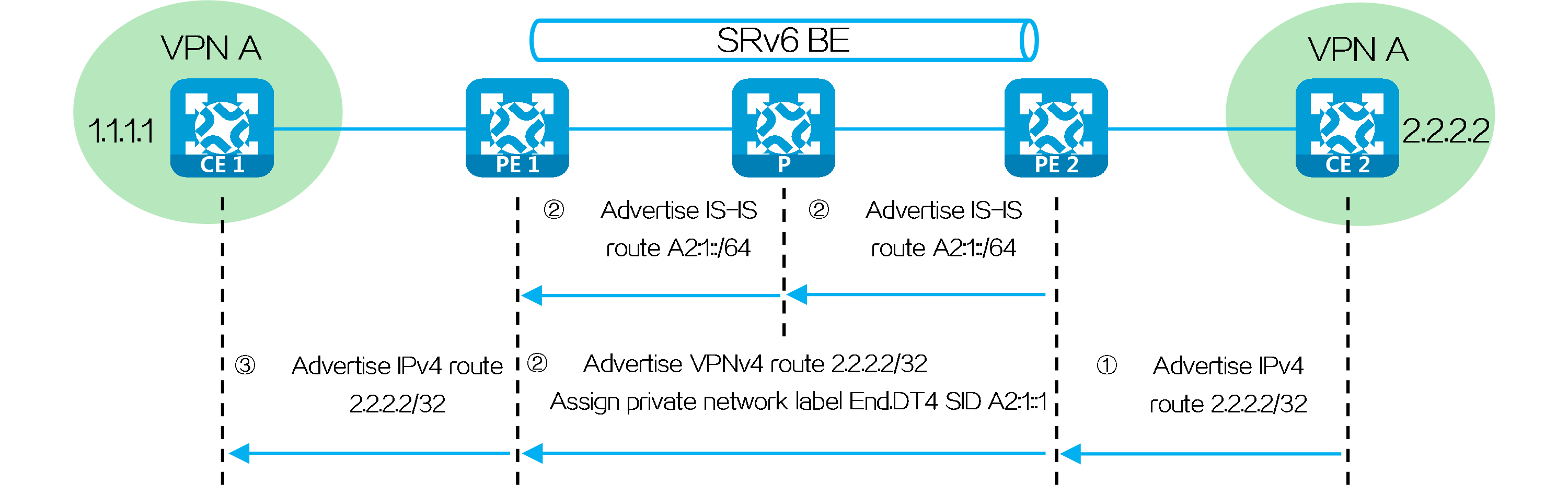
PE 2 advertises locator route A2:1::/64 associated with the End.DT4 SID to P and PE 1 through IGP (IS-IS for example). Upon receiving the IS-IS route, PE 1 and P learn it to their routing tables.
For example, CE 2 advertises a private network route to CE 1 through MP-BGP as follows:
(1) CE 2 advertises private network route 2.2.2.2/32 from the local site to PE 2 through IGP or BGP.
(2) Upon learning the route, PE 2 adds the route to the routing table of VPN instance A. PE 2 adds the RD and RT attributes to the private network route, and assigns End.DT4 SID A2:1::1 to it to form a VPNv4 route. PE 2 advertises the VPNv4 route to PE 1 through MP-BGP.
(3) Upon receiving the VPNv4 route, PE 1 adds it to the routing table of VPN instance A, converts the VPNv4 route to an IPv4 route, and advertises the route to CE 1.
(4) Upon receiving the route, CE 1 learns it to its routing table.
Figure25 Route advertisement for IPv4 L3VPN over SRv6 BE
Packet forwarding
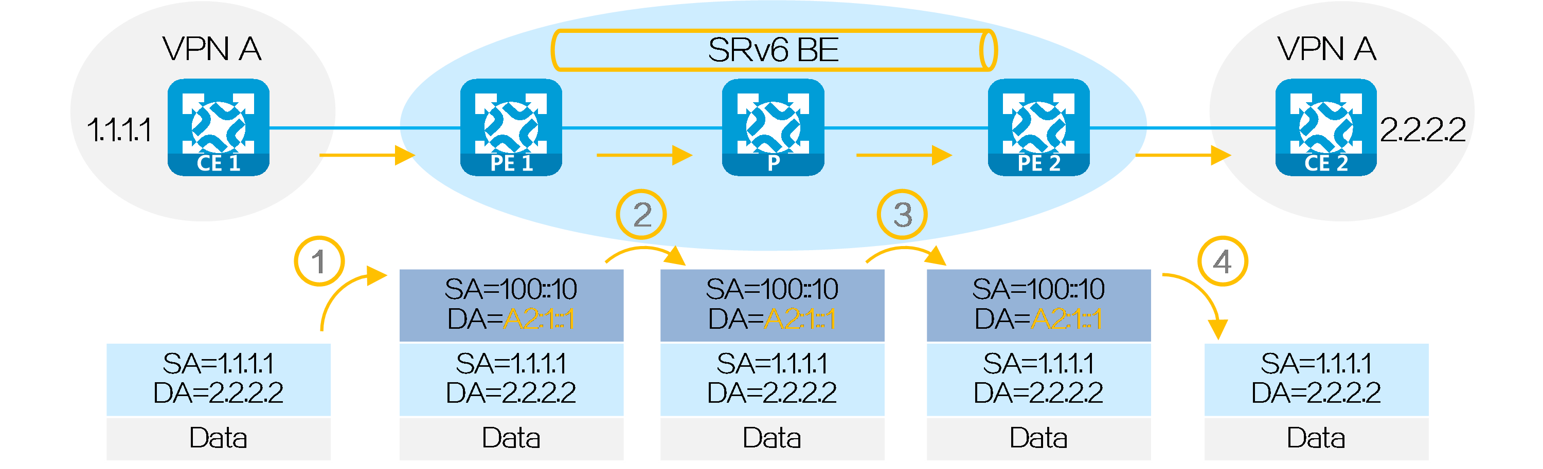
Packet forwarding based on End.DT4 SID/End.DT6 SID/End.DT46 SID
After route advertisement is completed, CE 1 forwards a packet with destination address 2.2.2.2 to CE 2 as follows:
(1) CE 1 sends an IPv4 packet with destination address 2.2.2.2 to PE 1.
(2) Upon receiving the packet from the interface bound to VPN instance A, PE 1 searches the route matching 2.2.2.2 in VPN instance A’s routing table. It obtains the route-associated End.DT4 SID A2:1::1, and encapsulates an IPv6 packet header for the packet. The source address in the IPv6 packet header is configured by the administrator, and the destination address is End.DT4 SID A2:1::1.
(3) PE 1 searches the IPv6 routing table based on End.DT4 SID A2:1::1, and forwards the packet to P through the optimal IGP route.
(4) P searches the IPv6 routing table based on End.DT4 SID A2:1::1, and forwards the packet to PE 2 through the optimal IGP route.
(5) Upon receiving the packet with End.DT4 SID A2:1::1 as the destination IPv6 address, PE 2 decapsulates the packet by removing is IPv6 packet header, searches the routing table of VPN instance A matching the End.DT4 SID, and forwards the packet to CE 2.
Figure26 Packet forwarding based on End.DT4 SID/End.DT6 SID/End.DT46 SID
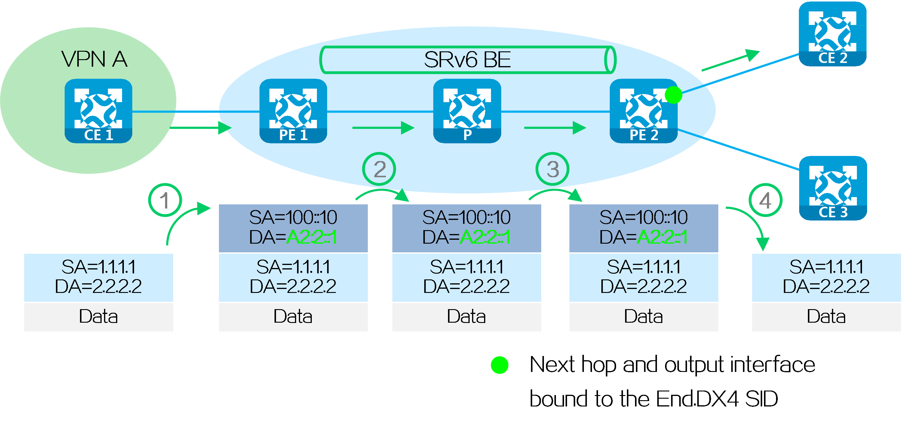
Packet forwarding based on End.DX4 SID/End.DX6 SID
After route advertisement is completed, CE 1 forwards a packet with destination address 2.2.2.2 to CE 2 as follows:
(1) CE 1 sends an IPv4 packet with destination address 2.2.2.2 to PE 1.
(2) Upon receiving the private network packet from the interface bound to VPN instance A, PE 1 searches the route matching 2.2.2.2 in VPN instance A’s routing table. It obtains the route-associated End.DX4 SID A2:2::1, and encapsulates an IPv6 packet header for the packet. The source address in the IPv6 packet header is configured by the administrator, and the destination address is End.DX4 SID A2:2::1.
(3) PE 1 searches the IPv6 routing table based on End.DX4 SID A2:2::1, and forwards the packet to P through the optimal IGP route.
(4) P searches the IPv6 routing table based on End.DX4 SID A2:2::1, and forwards the packet to PE 2 through the optimal IGP route.
(5) Upon receiving the packet with End.DX4 SID A2:2::1 as the destination IPv6 address, PE 2 decapsulates the packet by removing its IPv6 packet header, and forwards the packet based on the SID-associated next hop and output interface to CE 2.
Figure27 Packet forwarding based on End.DX4 SID/End.DX6 SID
4.5 L3VPN over SRv6 TE
Introduction
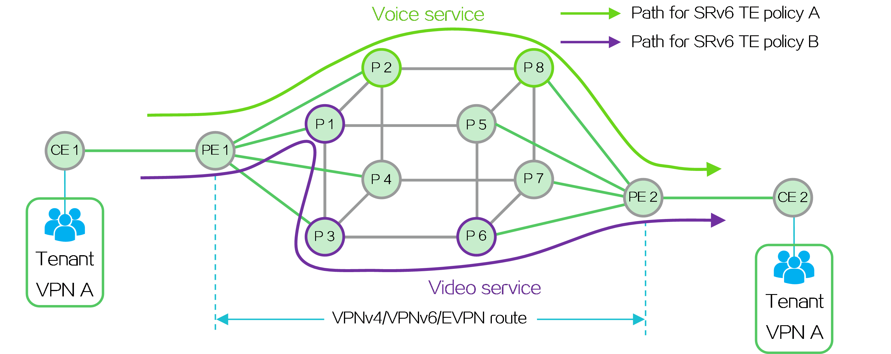
L3VPN over SRv6 TE adopts the forwarding paths corresponding to SRv6 TE policies (SRv6 TE policy tunnels) as public network tunnels to VPN service traffic, providing Layer 3 interconnections between users in the same VPN at different sites and implementing user isolation among different VPNs.
An L3VPN over SRv6 TE network can use various traffic steering methods to direct different service traffic in the VPN into different SRv6 TE tunnels to meet user demands. For example, it can forward low-delay voice service traffic based on the path of SRv6 TE policy A, and high-bandwidth video service traffic based on the path of SRv6 TE policy B.
Figure28 L3VPN over SRv6 TE network forwarding
Based on the carried VPN services, L3VPN over SRv6 TE is classified into the following types:
· IP L3VPN over SRv6 TE policy—Transmits private network routes through VPNv4/VPNv6 routes between PEs to carry Layer 3 VPN services.
· EVPN L3VPN over SRv6 TE policy—Transmits private network routes through EVPN routes between PEs to carry Layer 3 VPN services.
Technical benefits
Compared with L3VPN over SRv6 BE, L3VPN over SRv6 TE is more flexible and reliable for deployment.
Table2 Comparison between L3VPN over SRv6 TE and L3VPN over SRv6 BE
|
Technology |
L3VPN over SRv6 TE |
L3VPN over SRv6 BE |
|
Public network route advertisement |
All SRv6 nodes advertise their own locator routes in the public network. |
Only PEs advertise their own locator routes in the public network. |
|
Packet encapsulation at the source node |
SRH: Encapsulates the SID list of the SRv6 TE policy and the SRv6 SID to be assigned to the private network route. IPv6 basic header: The first SID in the SID list of the SRv6 TE policy is used as the destination address. |
The SRH is not encapsulated. IPv6 basic header: The SRv6 SID to be assigned to the private network route is used as the destination address. |
|
Packet forwarding on intermediate nodes |
The SRv6 nodes corresponding to the SID list forward packets based on the SRH. Other nodes forward packets according to routing table lookup. |
All nodes forward packets according to routing table lookup. |
Operating mechanism
In an L3VPN over SRv6 TE network, public network traffic is forwarded along the SID list of the SRv6 TE policy. The SID list contains the SRv6 SIDs corresponding to the SRv6 nodes through which the forwarding path must pass. Therefore, the intermediate nodes must support SRv6. To ensure reachability of the devices associated with the SRv6 SIDs in the SID list, each device must advertise the route of the locator network where the SRv6 SID resides, that is, the locator route. In an L3VPN over SRv6 BE network, public network traffic is forwarded according to routing table lookup based on IGP routes. Therefore, the intermediate nodes do not need to support SRv6.
The SRv6 SIDs used and private network route advertisement method are the same for L3VPN over SRv6 TE and L3VPN over SRv6 BE. The operating mechanism differences are as shown in the following table.
Table3 Operating mechanism comparison between L3VPN over SRv6 TE and L3VPN over SRv6 BE
|
Technology |
L3VPN over SRv6 TE |
L3VPN over SRv6 BE |
|
Public network route advertisement |
All SRv6 nodes advertise their own locator routes in the public network. |
Only PEs advertise their own locator routes in the public network. |
|
Packet encapsulation at the source node |
SRH: Encapsulates the SID list of the SRv6 TE policy and the SRv6 SID to be assigned to the private network route. IPv6 basic header: The first SID in the SID list of the SRv6 TE policy is used as the destination address. |
The SRH is not encapsulated. IPv6 basic header: The SRv6 SID to be assigned to the private network route is used as the destination address. |
|
Packet forwarding on intermediate nodes |
The SRv6 nodes corresponding to the SID list forward packets based on the SRH. Other nodes forward packets according to routing table lookup. |
All nodes forward packets according to routing table lookup. |
|
The route advertisement and packet forwarding processes of IP L3VPN over SRv6 TE policy are similar to those of EVPN L3VPN over SRv6 TE policy. This section uses IPv4 L3VPN over SRv6 TE policy to illustrate the processes. |
Route advertisement
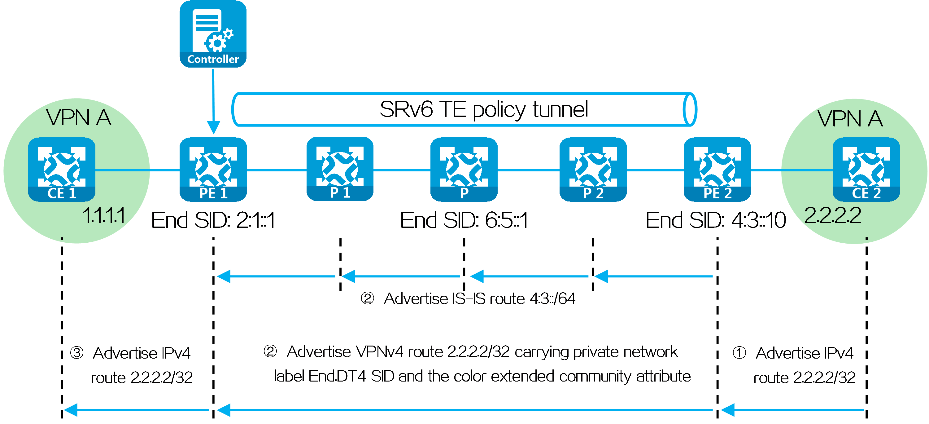
In an L3VPN over SRv6 TE network, SRv6 TE policy settings are typically deployed by the controller to PE 1. In the following figure, the SID list of the deployed SRv6 TE policy is <6:5::1, 4:3::10>, corresponding to SRv6 nodes P and PE 2. PE 1, P, and PE 2 use IGP to advertise locator routes in the public network.
PE 2 advertises network route 4:3::/64 associated with the End.DT4 SID to P 2, P, P 1, and PE 1 through IGP (IS-IS for example). Upon receiving the IGP route from PE 2, P 2, P, P 1, and PE 1 learn it to their routing tables. Similarly, P 2, P, P 1, and PE 1 also advertise their own locator routes.
Taking color-based traffic steering as an example, CE 2 advertises a private network route to CE 1 as follows:
(1) CE 2 advertises private network route 2.2.2.2/32 from the local site to PE 2 through IGP or BGP.
(2) Upon learning the route, PE 2 adds the route to the routing table of VPN instance A. PE 2 adds the RD and RT attributes to the private network route, and assigns End.DT4 SID 4:3::1 to it to form a VPNv4 route. PE 2 advertises the VPNv4 route carrying the End.DT4 SID and color extended community attribute to PE 1 through MP-BGP.
(3) Upon receiving the VPNv4 route, PE 1 adds it to the routing table of VPN instance A, and steers the VPNv4 route to the SRv6 TE policy by using the color-based traffic steering method. PE 1 converts the VPNv4 route to an IPv4 route, and advertises the route to CE 1.
(4) Upon receiving the private network route, CE 1 learns it to its routing table.
Figure29 Route advertisement for L3VPN over SRv6 TE
Packet forwarding
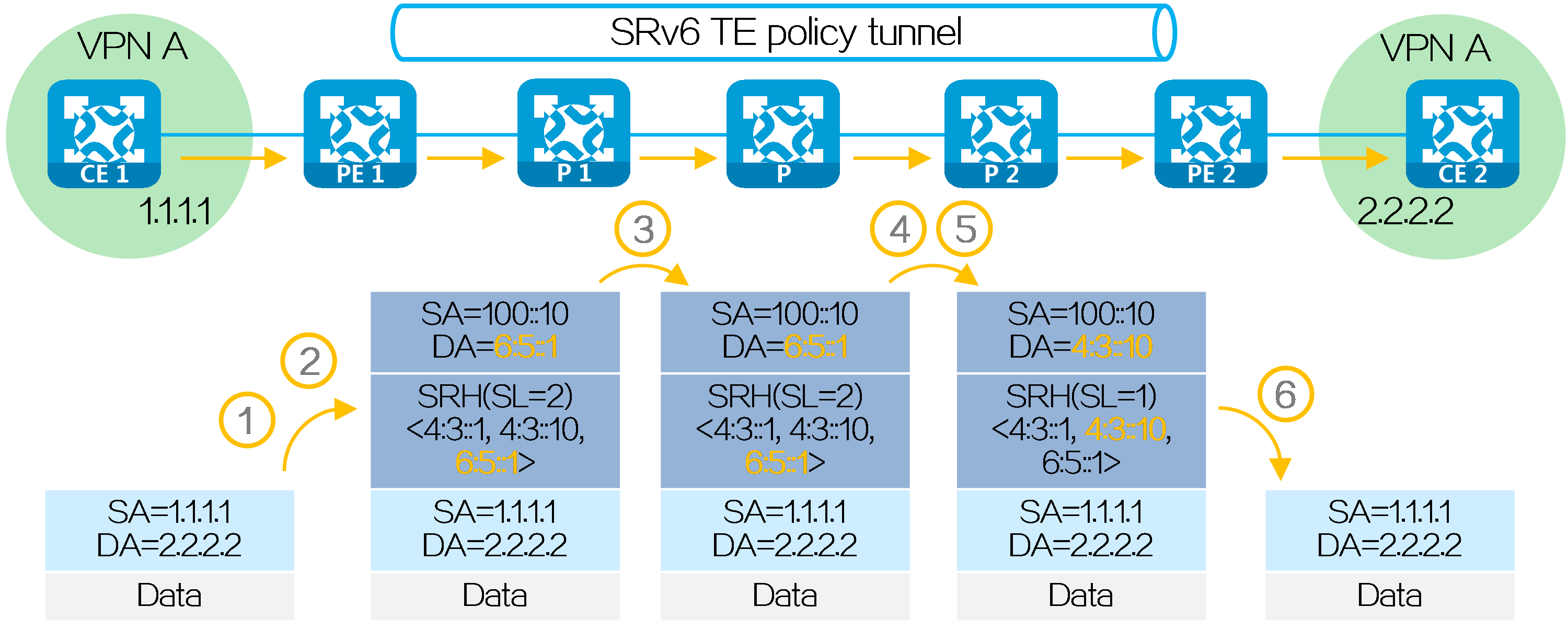
After route advertisement is completed, CE 1 forwards a packet with destination address 2.2.2.2 to CE 2 as follows:
(1) CE 1 sends an IPv4 packet with destination address 2.2.2.2 to PE 1.
(2) Upon receiving the private network packet from the interface bound to VPN instance A, PE 1 searches the route matching 2.2.2.2 in VPN instance A’s routing table. It obtains the route-associated End.DT4 SID 4:3::1. The next hop of the route is the SRv6 TE policy. Then PE 1 performs the following operations:
· Encapsulates SID list <6:5::1, 4:3::10> of the SRv6 TE policy and End.DT4 SID 4:3::1 in the SRH.
· Encapsulates the user-configured source address and destination address 6:5::1 (the first SID in the SID list of the SRv6 TE policy) to the IPv6 basic header.
· Searches the routing table based on the encapsulated destination address in the IPv6 header, and encapsulates and forwards the packet to P 1.
(3) P 1 searches the IPv6 routing table based on the destination address, and forwards the packet to P through the optimal IGP route.
(4) Upon receiving the packet, P performs the following operations:
· Checks the SL value in the SRH header. If the SL is greater than 0, it decreases the value by 1. The destination address is pointed by SL. Because the SL is 1, the destination address is IPv6 address 4:3::10 as pointed by Segment List [1].
· Searches the routing table based on the encapsulated destination address in the IPv6 header, and forwards the packet to P 2.
(5) P 2 searches the IPv6 routing table based on the destination address, and forwards the packet to PE 2 through the optimal IGP route.
(6) Upon receiving the packet, PE 2 uses the destination IPv6 address to search the local SID table, obtains the End SID, decreases the SL by 1, and updates the destination IPv6 address to End.DT4 SID 4:3::1. Then, PE 2 uses destination IPv6 address 4:3::1 to search the local SID table, obtains the End.DT4 SID, and executes the action associated with the End.DT4 SID. That is, it removes the IPv6 packet header, obtains VPN instance A matching the End.DT4 SID, searches the routing table of VPN instance A, and forwards the packet to CE 2.
Figure30 Packet forwarding for L3VPN over SRv6 TE
4.6 EVPN VPLS over SRv6
Introduction
EVPN VPLS over SRv6 uses SRv6 PW tunnels to carry EVPN VPLS services. PEs advertise SRv6 SIDs through BGP EVPN routes, and establish an SRv6 tunnel. The SRv6 tunnel is used as an SRv6 PW that encapsulates and forwards Layer 2 data packets between different sites, implementing point-to-multipoint connections for customer sites over the IPv6 backbone network.
Figure31 EVPN VPLS over SRv6 architecture
Operating mechanism
Figure32 Operating mechanism of EVPN VPLS over SRv6
SRv6 SIDs
In an EVPN VPLS over SRv6 network, PEs exchange SRv6 SIDs through BGP EVPN routes. Typically the SRv6 SIDs include the following types:
· End.DX2 SIDs and End.DT2U SIDs used for forwarding unicast traffic (whether to use End.DX2 SIDs or End.DT2U SIDs to forward unicast traffic depends on the configuration).
· End.DT2M SIDs used for forwarding EVPN VPLS broadcast, unknown unicast, and multicast (BUM) traffic.
The following table shows the relationship between SRv6 SID types and BGP EVPN routes.
Table4 Relationship between SRv6 SIDs and BGP EVPN routes
|
SRv6 SID type |
BGP EVPN routes carrying the SIDs |
SID functions |
|
End.DX2 SID |
AD per EVI route MAC/IP advertisement route |
Identifies an AC. The associated forwarding actions are removing the IPv6 packet header and extension header, and then forwarding the packet through the specified AC. |
|
End.DT2U SID |
AD per EVI route MAC/IP advertisement route |
Identifies a VSI. The associated forwarding actions are removing the IPv6 packet header and extension header, and then searching the MAC address table to forward the packet to the specified output interface. |
|
End.DT2M SID |
IMET route |
Identifies an VSI. The associated forwarding actions are removing the IPv6 packet header and extension header, and then broadcasting the packet within the VSI. |
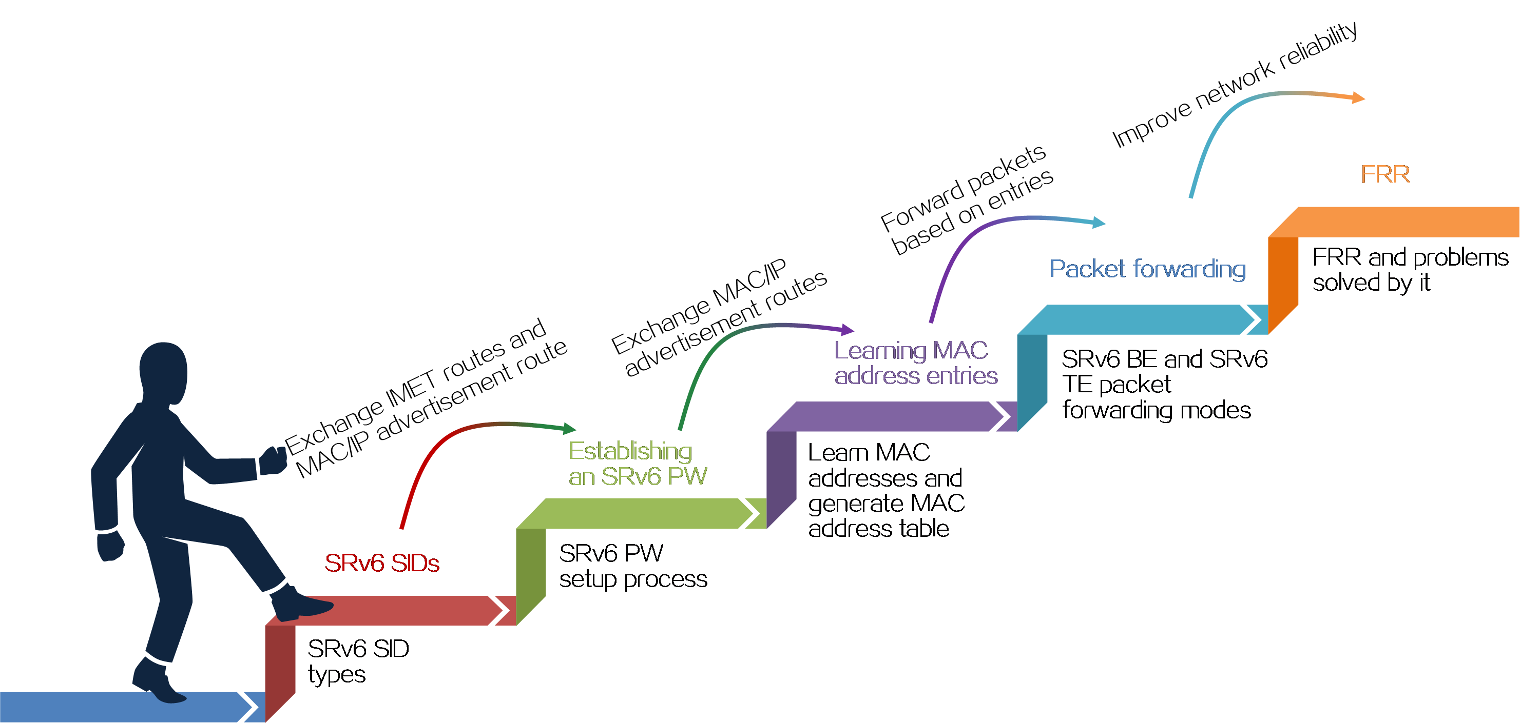
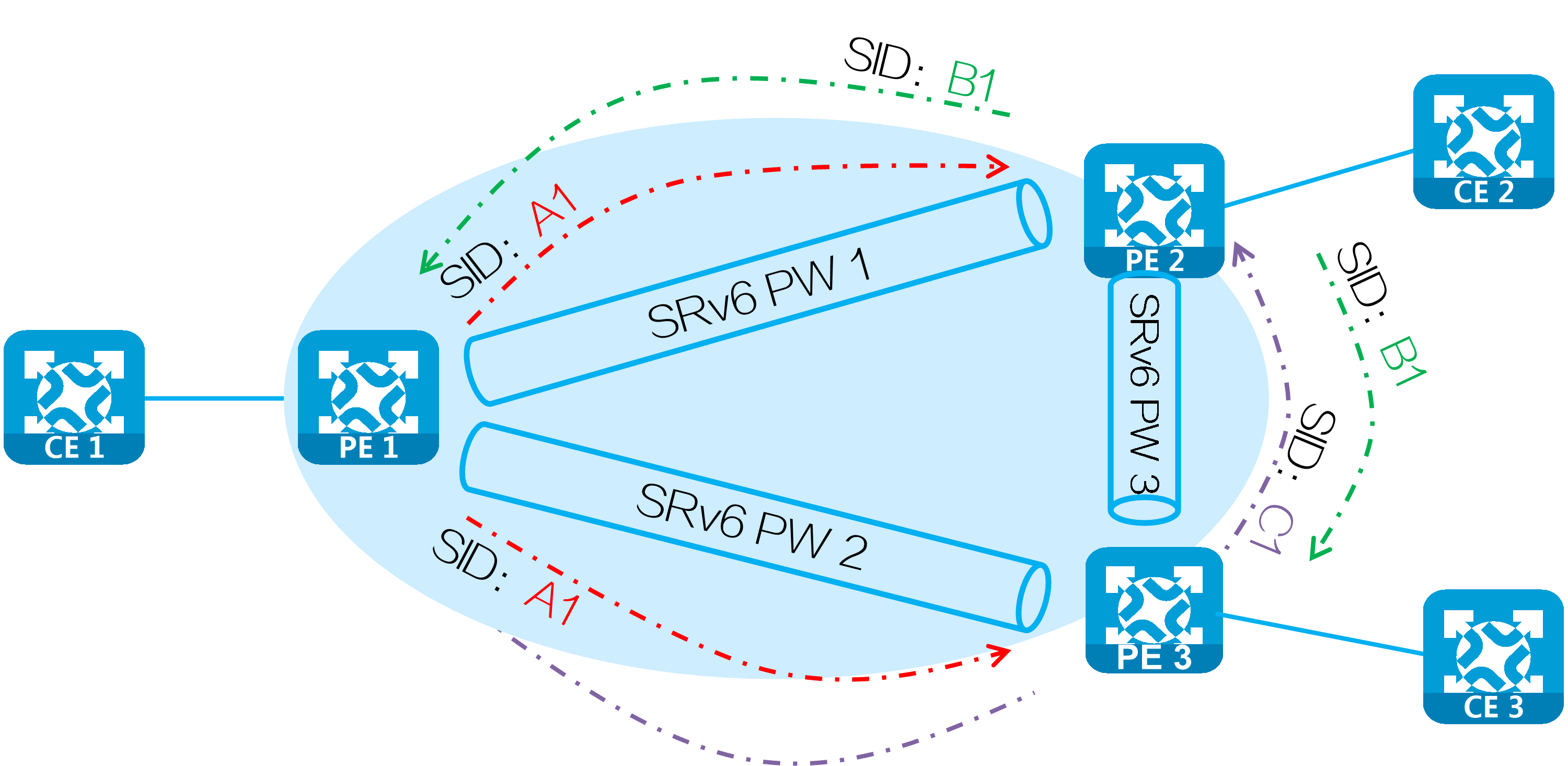
Establishing an SRv6 PW
PEs exchange SRv6 SIDs through BGP EVPN routes (IMET routes, AD per EVI routes, and MAC/IP advertisement routes) to establish an SRv6 PW. As shown in the following figure, PE 1 and PE 2 exchange IMET routes to establish an SRv6 PW as follows:
(1) PE 1 and PE 2 advertise IMET routes to each other, carrying the End.DT2M SID assigned to their VSIs.
(2) Upon receiving the IMET route, PE 1 and PE 2 each establishes a single-hop SRv6 tunnel to the remote PE. The SIDs of the tunnel are the End.DT2M SIDs in the routes.
(3) PE 1 establishes a single-hop SRv6 tunnel to the remote PE (PE 2). PE 2 establishes a single-hop SRv6 tunnel to the PE 1 in the same way. The two SRv6 tunnels form an SRv6 PW to carry Layer 2 data of users.
Figure33 Establishing an SRv6 PW
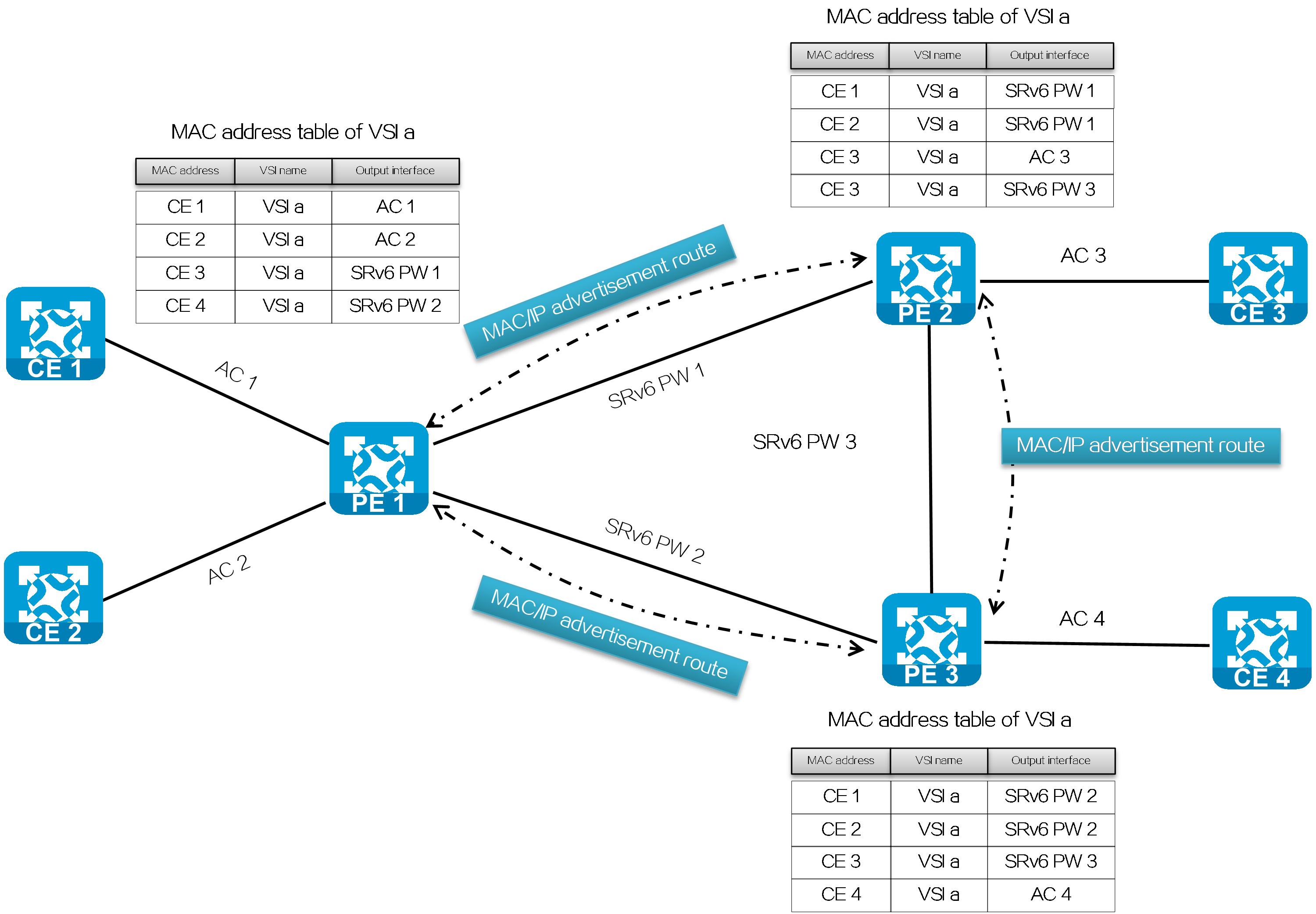
Learning MAC address entries
In the EVPN VPLS over SRv6 network, the PEs forward Layer 2 packets based on learned MAC address entries. The MAC address learning on the PEs includes the following parts:
· Local MAC address learning: Upon receiving a packet sent by the local CE, PE determines VSI to which the packet belongs, and adds the source MAC address (MAC address of the local CE) in the packet to the MAC address table of the VSI. The output interface of the MAC address entry is the AC that receives the packet.
· Remote MAC address learning: The PE advertises the MAC address learned through the MAC/IP advertisement route to the remote PE. Upon receiving the information, the remote PE adds the MAC address to the MAC address table of the associated VSI. The output interface of the MAC address entry is the SRv6 PW between the two PEs.
Figure34 MAC address learning for EVPN VPLS over SRv6
Packet forwarding
The packet forwarding modes supported by EVPN VPLS over SRv6 are SRv6-BE, SRv6-TE, and SRv6-TE and SRv6-BE hybrid modes. The packet forwarding modes have the following differences.
Table5 Differences between packet forwarding modes for EVPN VPLS over SRv6
|
Forwarding mode |
SRv6 TE mode |
SRv6 BE mode |
|
Forwarding principle |
Searches for a matching SRv6 TE policy based on packet attributes, adds the SRH containing the End.DX2 SID (or End.DT2M SID or End.DT2U SID) and SRv6 TE policy SID list to the packet, and forwards the packet through the SRv6 TE policy. |
Forwards the packet according to IPv6 routing table lookup based on the encapsulated End.DX2 SID, End.DT2M SID, or End.DT2U SID. |
|
Forwarding path |
Supports traffic steering methods based on color and tunnel policy. You can flexibly select traffic steering methods according to forwarding requirements. Implements forwarding path control by planning SID lists in SRv6 TE policies. You can select appropriate forwarding paths according to service requirements. |
Uses IGP to calculate forwarding paths. The forwarding paths cannot be planned. |
|
Reliability |
An SRv6 TE policy contains multiple candidate paths, and supports backup between primary and backup paths. |
The speed of forwarding path switchover upon network failures depends on the route convergence speed. |
|
Load sharing |
A candidate path contains multiple SID lists, and can implement load sharing based on the SID list weights. |
Implements load sharing based on locator routes. |
In SRv6 TE and SRv6 BE hybrid mode, the SRv6 TE mode is preferentially used to select forwarding paths. If no SRv6 TE policy is available, the SRv6 BE mode is used to select forwarding paths.
SRv6 BE
Known unicast packets
Figure35 Unicast packet forwarding process in the EVPN VPLS over SRv6 BE network
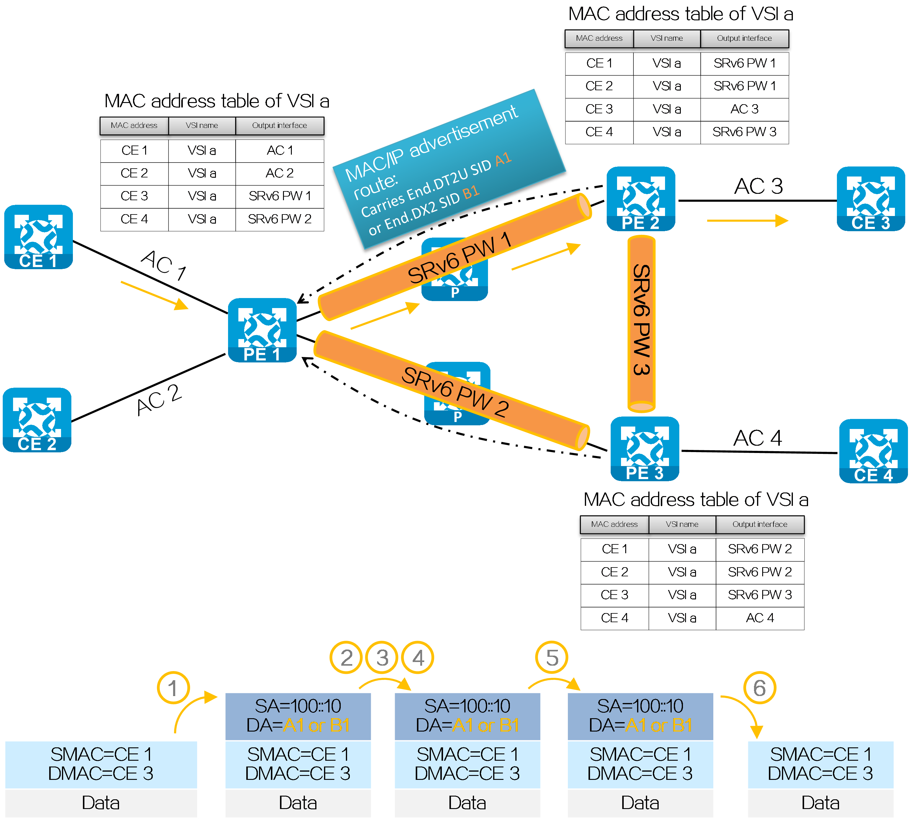
As shown in the figure above, after SRv6 PW establishment is completed, CE 1 forwards a known unicast packet to CE 3 process in the EVPN VPLS over SRv6 BE network as follows:
(1) CE 1 sends a Layer 2 packet with destination MAC address of CE 2 to PE 1.
(2) Upon receiving the Layer 2 packet on the AC connected to CE 1, PE 1 searches the MAC address table in the AC-associated VSI, finds the associated output interface SRv6 PW 1, and obtains the End.DT2U SID or End.DX2 SID of the tunnel (that is, End.DT2U SID A1 or End.DX2 SID B1 assigned by PE 2).
(3) PE 1 encapsulates the outer IPv6 packet header for the packet, with End.DT2U SID A1 or End.DX2 SID B1 as the destination IPv6 address and 100::10 (configured source address in the IPv6 packet header encapsulated for EVPN VPLS over SRv6) as the source IPv6 address.
(4) PE 1 searches the IPv6 routing table based on End.DT2U SID A1 or End.DX2 SID B1, and forwards the packet to P through the optimal IGP route.
(5) P searches the IPv6 routing table based on End.DT2U SID A1 or End.DX2 SID B1, and forwards the packet to PE 2 through the optimal IGP route.
(6) PE 2 searches the local SID table based on End.DT2U SID A1 or End.DX2 SID B1, and executes the SID-associated forwarding action.
· For End.DT2U SID, PE 2 decapsulates the packet by removing its IPv6 packet header, searches the MAC address table in the VSI to which the End.DT2U SID belongs, and forwards the packet to CE 2 according to the search result.
· For End.DX2 SID, PE 2 decapsulates the packet by removing its IPv6 packet header, and forwards the packet to the AC associated with the End.DX2 SID.
Broadcast, multicast, and unknown unicast packets
Figure36 Unknown unicast packet forwarding process in the EVPN VPLS over SRv6 BE network
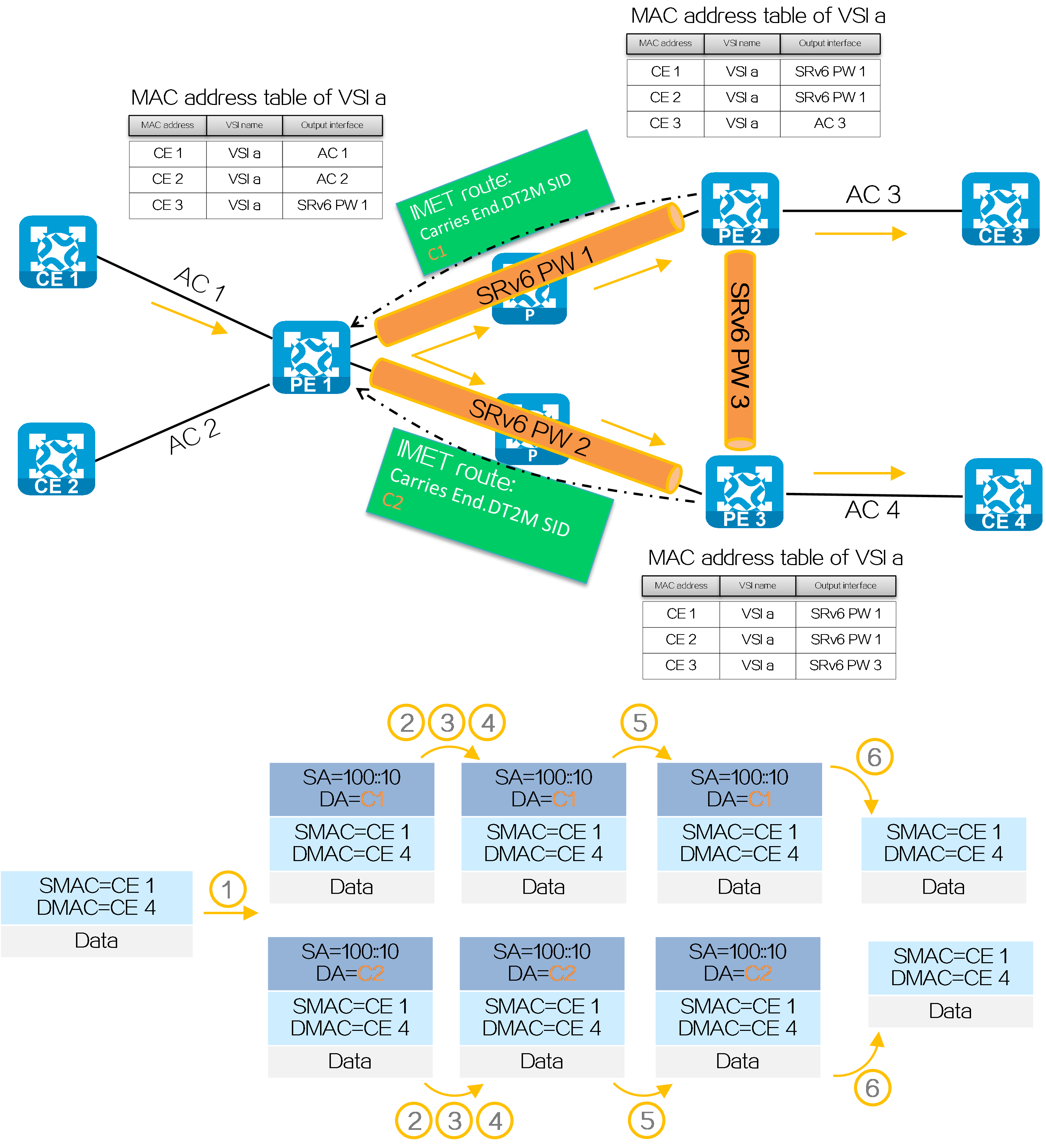
As shown in the figure above, if SRv6 PW establishment is completed but PE 1 has not learned the MAC address of CE 4, CE 1 forwards an unknown unicast packet to CE 4 process in the EVPN VPLS over SRv6 BE network as follows:
(1) CE 1 sends a Layer 2 packet with destination MAC address of CE 4 to PE 1.
(2) After receiving the Layer 2 packet on the AC connected to CE 1, PE 1 fails to obtain a matching MAC address entry in the MAC address table of the AC-associated VSI, and then searches for the End.DT2M SID assigned by PE 2 and PE 3 in the VSI.
(3) PE 1 encapsulates the outer IPv6 packet header for the packet. The destination IPv6 address for the packet sent to PE 2 is End.DT2M SID C1. The destination IPv6 address for the packet sent to PE 3 is End.DT2M SID C2. The source IPv6 address for both packets is 100::10 (configured source address in the IPv6 packet header encapsulated for EVPN VPLS over SRv6).
(4) PE 1 searches the IPv6 routing table based on the End.DT2M SID, and forwards the packet to P through the optimal IGP route.
(5) P searches the IPv6 routing table based on the End.DT2M SID, and forwards the packet to PE 2 and PE 3 through the optimal IGP routes.
(6) PE 2 and PE 3 search the local SID tables based on the End.DT2M SID, and execute the SID-associated action, that is, removing the IPv6 packet headers and broadcasting the packets within the VSI to which the End.DT2M SID belongs.
|
|
SRv6 TE mode
Figure37 Packet forwarding process for EVPN VPLS over SRv6 TE

As shown in the figure above, after SRv6 PW establishment is completed, PE 1, P, and PE 2 are SRv6 nodes, and P 1 and P 2 are non-SRv6 nodes. CE 1 forwards a packet to CE 2 in the EVPN VPLS over SRv6 TE network as follows:
(1) CE 1 sends a Layer 2 packet with the destination MAC address of CE 2 to PE 1.
(2) After receiving the Layer 2 packet on the AC connected to CE 1, PE 1 searches the MAC address table in the AC-associated VSI.
· If a matching MAC address is found, PE 1 obtains the End.DT2U SID or End.DX2 SID of the SRv6 PW (output interface of the matching entry).
· If not matching MAC address is found, it obtains the End.DT2M SID assigned by PE 2. If PE 1 has End.DT2M SIDs received from multiple remote PEs, it encapsulates an End.DT2M SID for each Layer 2 packet, and forwards the packets to all the remote PEs.
¡ Upon obtaining the End.DT2U SID or End.DX2 SID, PE 1 obtains the SRv6 TE policy based on the next hop of the MAC/IP advertisement route carrying the SID. Upon obtaining the End.DT2M SID, PE 1 obtains the SRv6 TE policy based on the next hop of the IMET route carrying the SID.
¡ Encapsulates SID list <6:5::1, 4:3::10> of the SRv6 TE policy and SID 4:3::1 obtained in step 2 in the SRH. (Use the obtained End.DT2U SID 4:3::1 as an example.)
¡ Encapsulates the user-configured source address and destination address 6:5::1 (the first SID in the SID list of the SRv6 TE policy) to the IPv6 basic header.
¡ Searches the routing table based on the encapsulated destination address in the IPv6 header, and encapsulates and forwards the packet to P 1.
(3) P 1 searches the IPv6 routing table based on the destination address, and forwards the packet to P through the optimal IGP route.
(4) Upon receiving the packet, P performs the following operations:
· Checks the SL value in the SRH header. If the SL is greater than 0, it decreases the value by 1. The destination address is as pointed by SL. Because the SL is 1, the destination address is IPv6 address 4:3::10 as pointed by Segment List [1].
· Searches the routing table based on the encapsulated destination address in the IPv6 header, and forwards the packet to P 2.
(5) P 2 searches the IPv6 routing table based on the destination address, and forwards the packet to PE 2 through the optimal IGP route.
(6) PE 2 searches the local SID table based on the SIDs carried in the packet. It first removes the End SID, and then searches the local SID table based on the next SID. PE 2 processes SIDs differently by SID type as follows:
· For End.DT2U SID, PE 2 decapsulates the packet by removing its IPv6 packet header, searches the MAC address table in the VSI to which the End.DT2U SID belongs, and forwards the packet to CE 2 according to the search result.
· For End.DX2 SID, PE 2 decapsulates the packet by removing its IPv6 packet header, and forwards the packet to the AC associated with the End.DX2 SID.
· For End.DT2M SID, PE 2 decapsulates the packet by removing its IPv6 packet header, and then broadcasts the packet within the VSI to which the End.DT2M SID belongs.
FRR
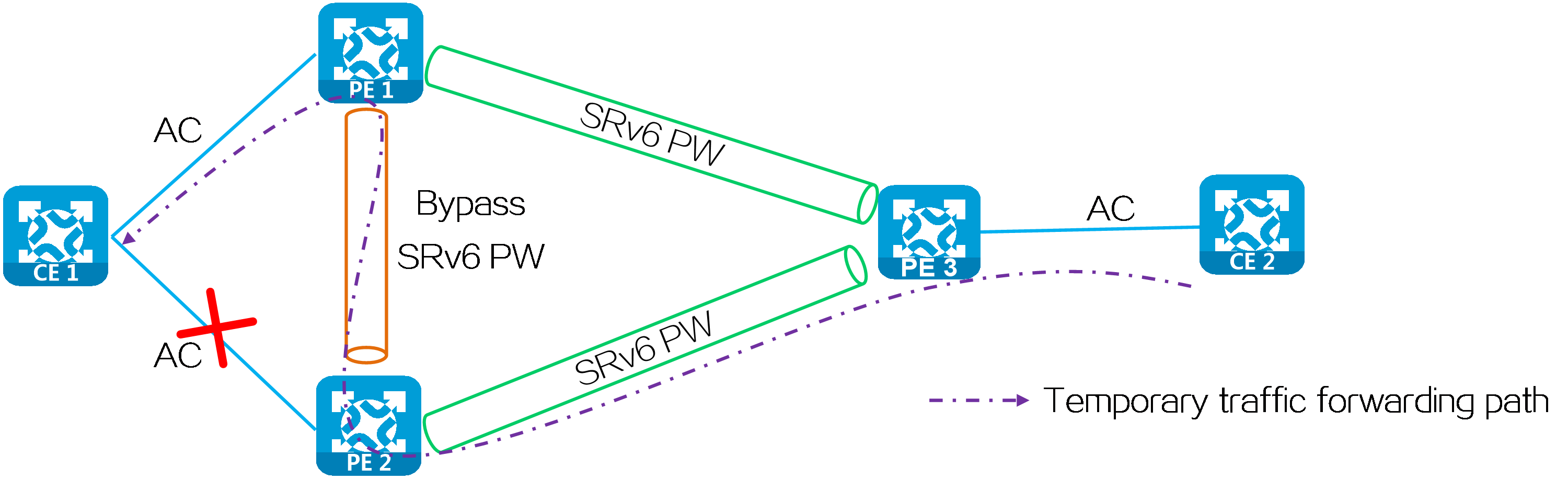
In a multi-homed network, when the AC attached to PE 2 fails, PE 2 deletes the corresponding MAC address entry and advertises the local unreachable event to PE 1 and remote PEs (PE 3 in this example). During this period of time, the packets sent by PE 3 to PE 2 will be discarded due to failure to find an output interface. To address this issue, you can configure FRR for EVPN VPLS over SRv6. With FRR enabled, PE 2 does not delete the corresponding MAC address entry when the attached AC fails. Instead, it forwards the packet matching the MAC address entry to PE 1 through the bypass SRv6 PW between PE 2 and PE 1. Upon receiving the packet, PE 1 forwards the packet to CE 1 to prevent packet loss due to the AC failure.
Figure38 FRR network
As shown in the following figure, a loop might exist if PE 1 and PE 2 establish a bypass SRv6 PW between them through End.DT2U or End.DX2 SIDs. When the ACs on PE 1 and PE 2 both fail, PE 1 or PE 2 forwards the packets received from its peer back to its peer through the bypass SRv6 PW.
Figure39 Bypass SRv6 PW established through End.DT2U or End.DX2 SIDs
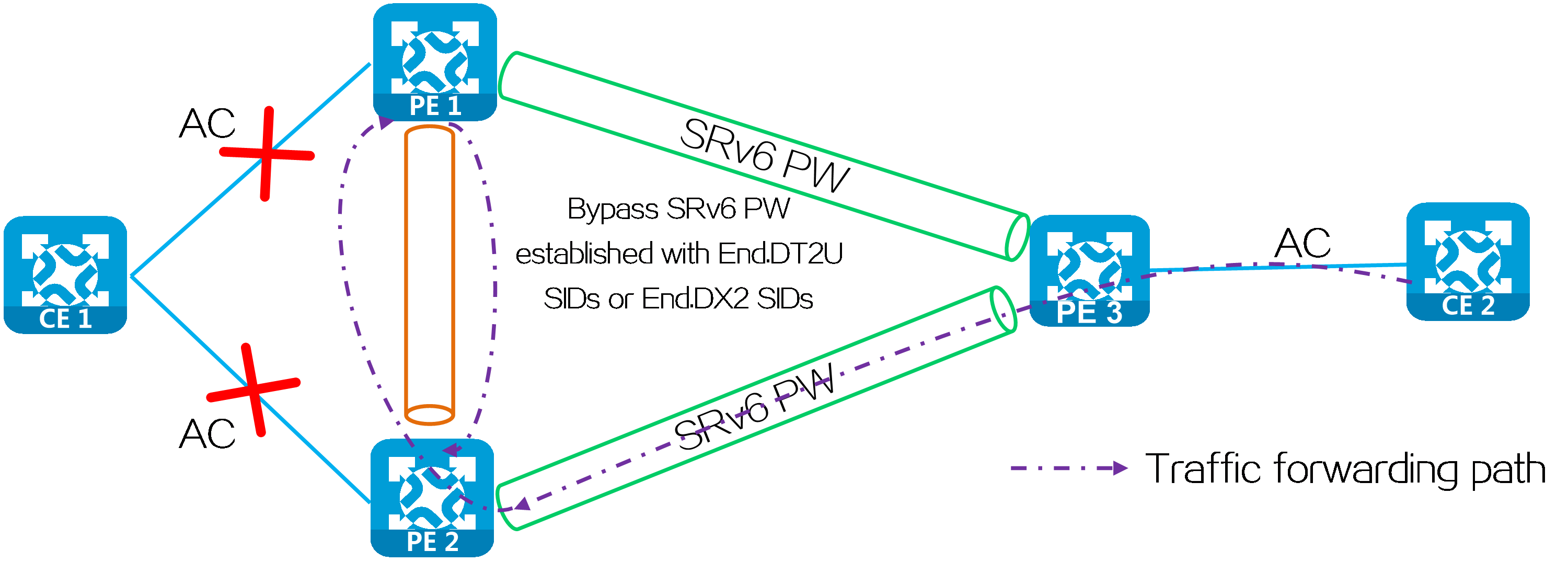
To resolve this issue, use End.DT2UL or End.DX2L SIDs to establish a bypass SRv6 PW between PE 1 and PE 2. The packets from a bypass SRv6 PW carry an End.DT2UL or End.DX2L SID. A PE does not forward the packets back to the bypass SRv6 PW.
Typical networking
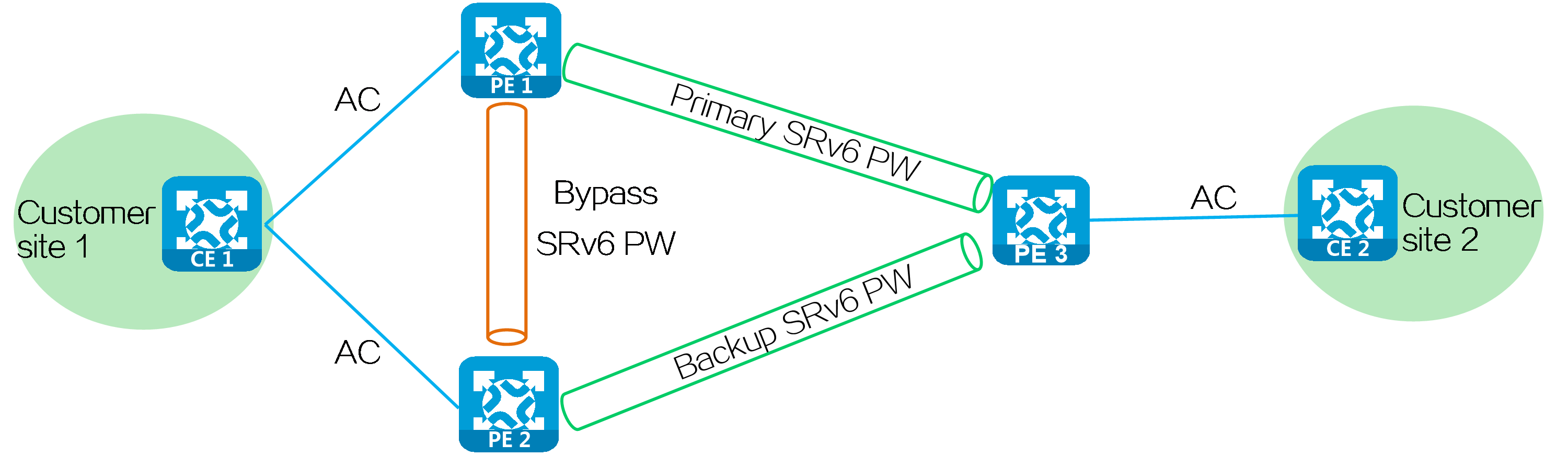
Multi-homed + FRR networking
CE 1 is dual-homed to PE 1 and PE 2 through link aggregation or S-Trunk. CE 2 is single-homed to PE 3. You can establish SRv6 PWs in the network to implement interconnection between customer sites. You can deploy FRR to minimize impact on the network caused by AC or SRv6 PW failures, improving network reliability and stability.
Figure40 Multi-homed + FRR networking
4.7 EVPN VPWS over SRv6
Introduction
EVPN VPWS over SRv6 uses SRv6 PW tunnels to carry EVPN VPWS services. PEs advertise SRv6 SIDs through BGP EVPN routes, and establish an SRv6 tunnel. The SRv6 tunnel is used as an SRv6 PW that encapsulates and forwards Layer 2 data packets between different sites, implementing transparent forwarding of Layer 2 customer traffic over the IPv6 backbone network and establishment of point-to-point connections between customer sites over the IPv6 backbone network.
Figure41 EVPN VPWS over SRv6 architecture
Operating mechanism
Figure42 Operating mechanism of EVPN VPWS over SRv6
SRv6 SIDs
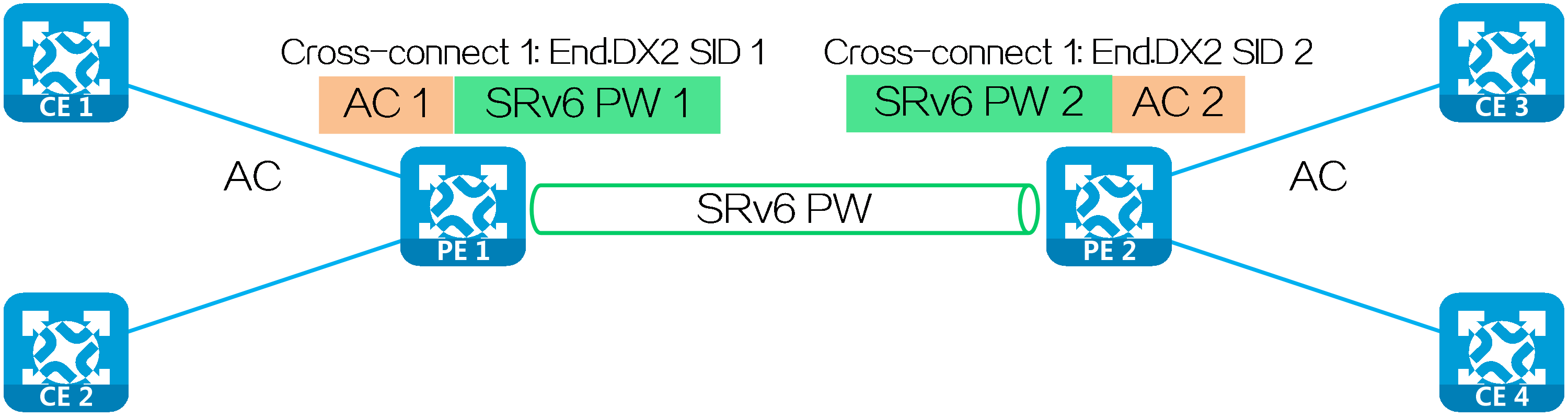
The SRv6 SIDs used in an EVPN VPWS over SRv6 network are typically End.DX2 SIDs.
End.DX2 SIDs
A PE assigns an End.DX2 SID to each cross-connect. PEs exchange End.DX2 SIDs through AD per EVI routes to establish an SRv6 PWs.
Upon receiving a packet carrying an End.DX2 SID, the PE decapsulates the packet, obtains the AC based on the cross-connect identified by the End.DX2 SID, and forwards the packet to the CE through the AC.
|
|
Figure43 EVPN VPWS over SRv6 networking
Establishing an SRv6 PW
Dynamically establishing an SRv6 PW
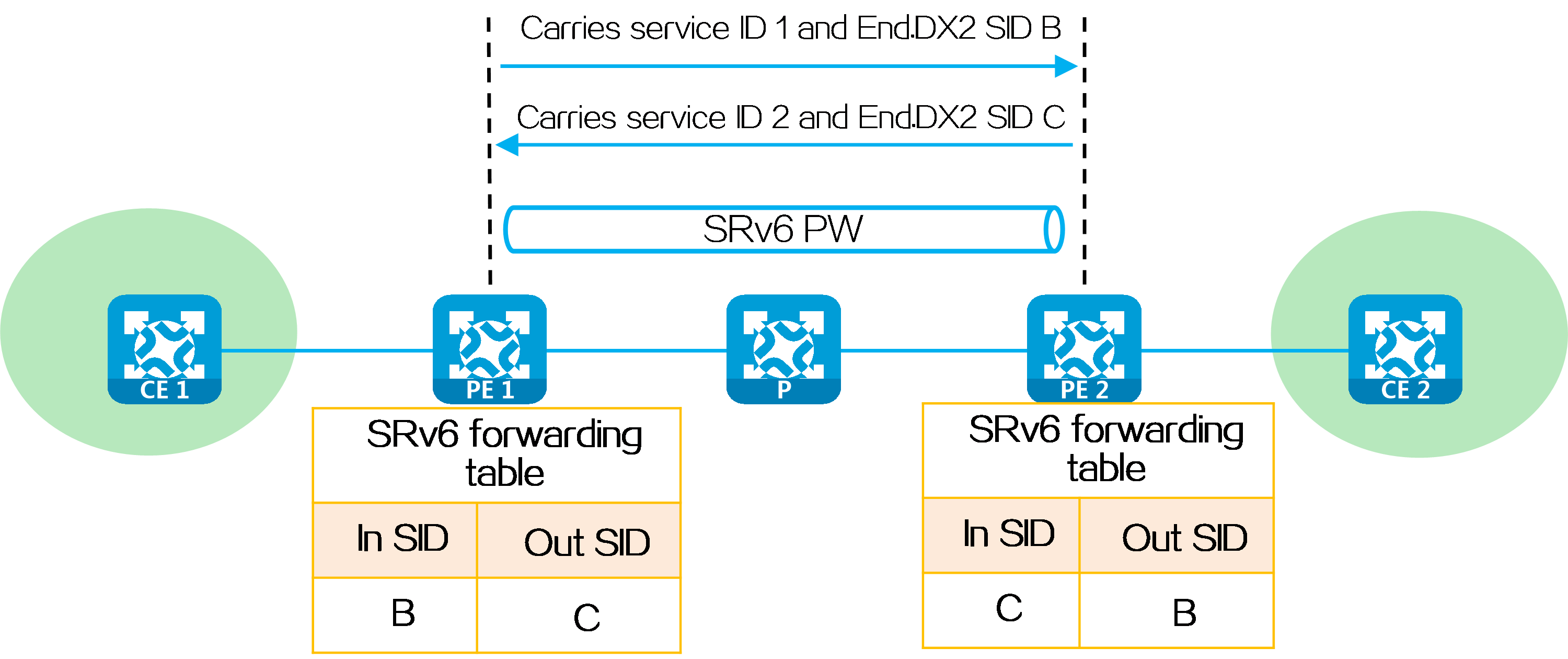
PEs exchange End.DX2 SIDs through BGP EVPN routes to dynamically establish an SRv6 PW. The process for dynamically establishing an SRv6 PW is as follows:
(1) When advertising an EVPN Ethernet auto-discovery route to PE 2, PE 1 carries the local service ID and the End.DX2 SID assigned to the cross-connect in the route.
(2) Upon receiving the EVPN route carrying the same service ID as the locally configured remote service ID, PE 2 establishes a single-hop SRv6 tunnel to the PE 1. The SID of the tunnel is the End.DX2 SID in the route.
(3) After PE 1 and PE 2 both advertise End.DX2 SIDs and establish unidirectional single-hop SRv6 tunnels to each other, the SRv6 tunnels form a PW to carry Layer 2 user data. The PW is called an SRv6 PW.
Figure44 Dynamically establishing an SRv6 PW
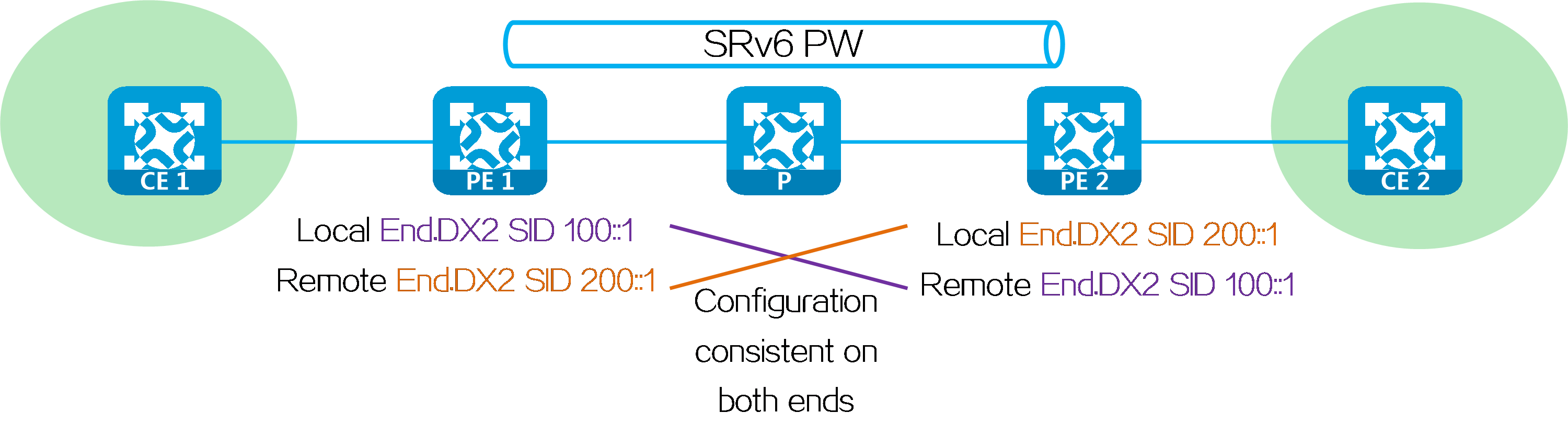
Statically establishing an SRv6 PW
To statically establish an SRv6 PW between two PEs, configure the SRv6 SIDs assigned by both the local and remote ends to the cross-connects on the PEs.
Figure45 Statically establishing an SRv6 PW
Packet forwarding
The packet forwarding modes supported by EVPN VPWS over SRv6 are SRv6-BE, SRv6-TE, and SRv6-TE and SRv6-BE hybrid modes. The packet forwarding modes have the following differences.
Table6 Differences between packet forwarding modes for EVPN VPWS over SRv6
|
Forwarding mode |
SRv6 TE mode |
SRv6 BE mode |
|
Forwarding principle |
Searches for a matching SRv6 TE policy based on packet attributes, adds the SRH containing the End.DX2 SID and SRv6 TE policy SID list to the packet, and forwards the packet through the SRv6 TE policy. |
Forwards the packet according to IPv6 routing table lookup based on the encapsulated End.DX2 SID. |
|
Forwarding path |
Supports traffic steering methods based on color and tunnel policy. You can flexibly select traffic steering methods according to forwarding requirements. Implements forwarding path control by planning SID lists in SRv6 TE policies. You can select appropriate forwarding paths according to service requirements. |
Uses IGP to calculate forwarding paths. The forwarding paths cannot be planned. |
|
Reliability |
An SRv6 TE policy contains multiple candidate paths, and supports backup between primary and backup paths. |
The speed of forwarding path switchover upon network failures depends on the route convergence speed. |
|
Load sharing |
A candidate path contains multiple SID lists, and can implement load sharing based on the SID list weights. |
Implements load sharing based on locator routes. |
In SRv6 TE and SRv6 BE hybrid mode, the SRv6 TE mode is preferentially used to select forwarding paths. If no SRv6 TE policy is available, the SRv6 BE mode is used to select forwarding paths.
SRv6 BE mode
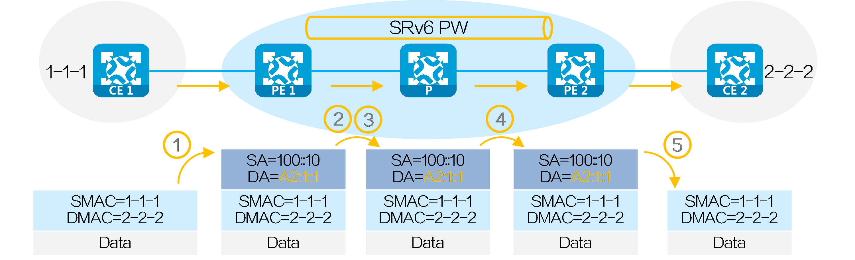
After SRv6 PW establishment is completed, CE 1 forwards a packet to CE 2 in the EVPN VPWS over SRv6 BE network as follows:
(1) CE 1 sends a Layer 2 packet with destination MAC address 2-2-2 to PE 1.
(2) After receiving the Layer 2 packet on the AC connected to CE 1, PE 1 searches for the SRv6 PW associated with the AC, and obtains End.DX2 SID A2:1::1 (End.DX2 SID assigned by PE 2 to the cross-connect). Then, PE 1 encapsulates the outer IPv6 packet header for the packet, with End.DX2 SID A2:1::1 as the destination IPv6 address and 100::10 (configured source address in the IPv6 packet header encapsulated for EVPN VPWS over SRv6) as the source IPv6 address.
(3) PE 1 searches the IPv6 routing table based on End.DX2 SID A2:1::1, and forwards the packet to P through the optimal IGP route.
(4) P searches the IPv6 routing table based on End.DX2 SID A2:1::1, and forwards the packet to PE 2 through the optimal IGP route.
(5) PE 2 searches the local SID table based on the End.DX2 SID, and executes the SID-associated action, that is, removing the outer IPv6 packet header, obtaining the AC matching the End.DX2 SID, and forwarding the packet to CE 2 through the AC.
Figure46 Packet forwarding process for EVPN VPWS over SRv6 BE
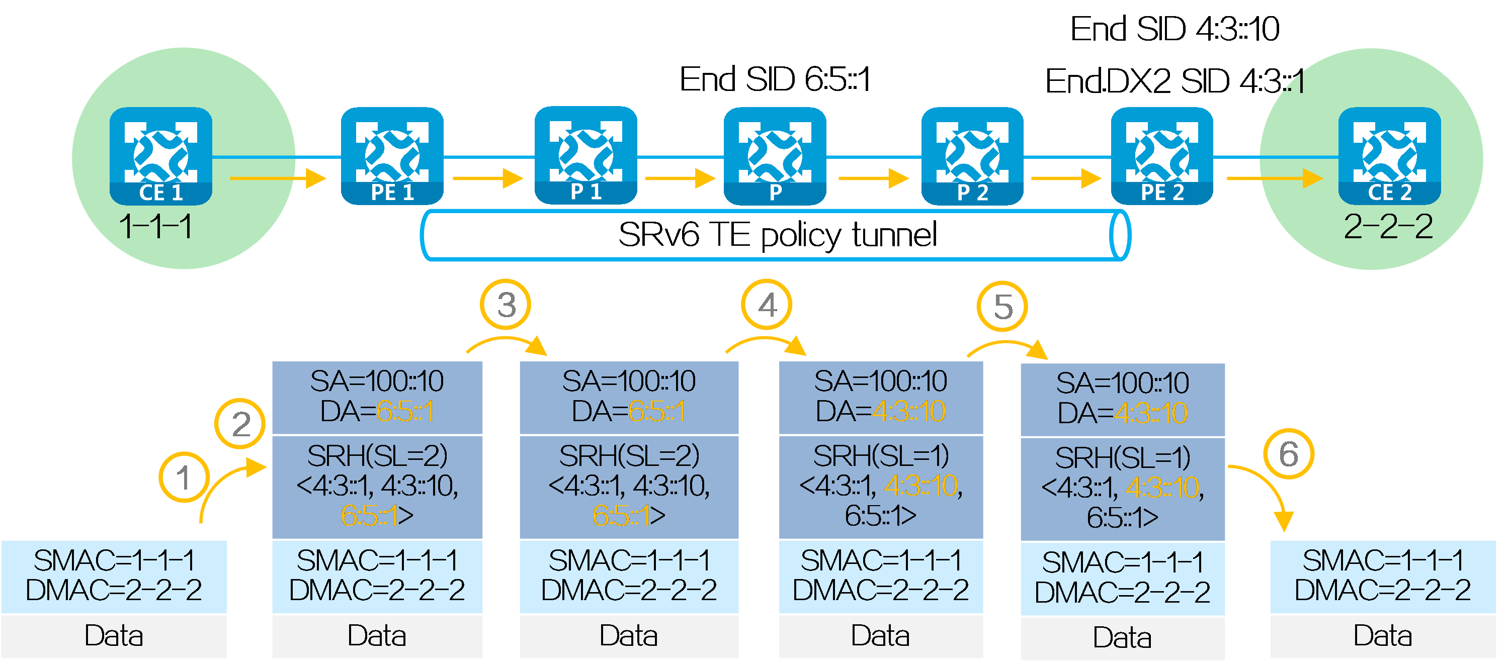
SRv6 TE mode
After SRv6 PW establishment is completed, PE 1, P, and PE 2 are SRv6 nodes, and P 1 and P 2 are non-SRv6 nodes. CE 1 forwards a packet to CE 2 in the EVPN VPWS over SRv6 TE network as follows:
(1) CE 1 sends a Layer 2 packet with destination MAC address 2-2-2 to PE 1.
(2) After receiving the Layer 2 packet on the AC connected to CE 1, PE 1 searches for the SRv6 PW associated with the AC, and obtains End.DX2 SID 4:3::1. The next hop of the route is an SRv6 TE policy. Then PE 1 performs the following operations:
· Encapsulates SID list <6:5::1, 4:3::10> of the SRv6 TE policy and End.DX2 SID 4:3::1 in the SRH.
· Encapsulates the user-configured source address and destination address 6:5::1 (the first SID in the SID list of the SRv6 TE policy) to the IPv6 basic header.
· Searches the routing table based on the encapsulated destination address in the IPv6 header, and encapsulates and forwards the packet to P 1.
(3) P 1 searches the IPv6 routing table based on the destination address, and forwards the packet to P through the optimal IGP route.
(4) Upon receiving the packet, P performs the following operations:
· Checks the SL value in the SRH header. If the SL is greater than 0, it decreases the value by 1. The destination address is as pointed by SL. Because the SL is 1, the destination address is IPv6 address 4:3::10 as pointed by Segment List [1].
· Searches the routing table based on the encapsulated destination address in the IPv6 header, and forwards the packet to P 2.
(5) P 2 searches the IPv6 routing table based on the destination address, and forwards the packet to PE 2 through the optimal IGP route.
(6) PE 2 searches the local SID table based on the End.DX2 SID, and executes the SID-associated action, that is, removing the outer IPv6 packet header, obtaining the AC matching the End.DX2 SID, and forwarding the packet to CE 2 through the AC.
Figure47 Packet forwarding process for EVPN VPWS over SRv6 TE
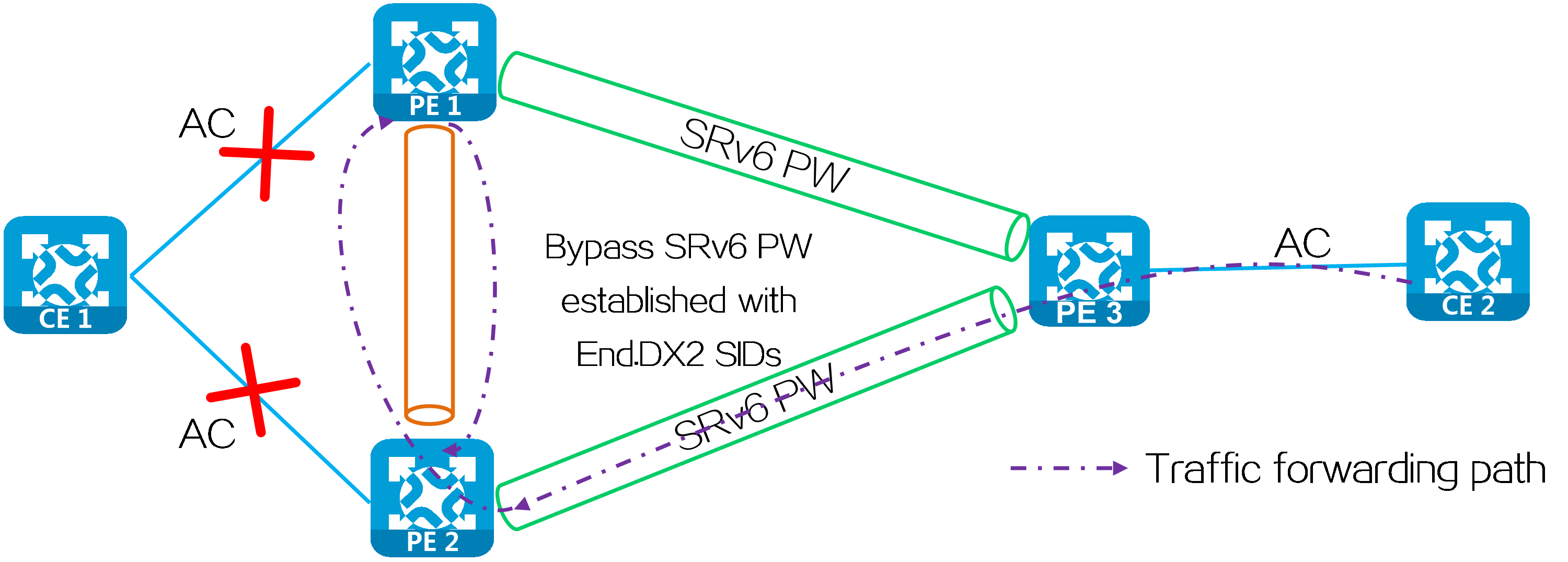
Bypass PW
In multi-homed site or primary/backup SRv6 PW network, when the AC on PE 2 fails, PE 2 notifies PE 1 and PE 3 of the local unreachable event. Then traffic is no longer forwarded through the SRv6 PW between PE 3 and PE 2. During this period of time, data packets sent from PE 3 to PE 2 cannot be forwarded to CE 1 and will be discarded. To address this issue, you can configure bypass PW for EVPN VPWS over SRv6 by establishing a bypass SRv6 PW between redundant PEs. When an AC failure occurs, PE 2 temporarily forwards traffic to PE 1 through the bypass SRv6 PW. PE 1 then forwards traffic to CE 1 to prevent traffic loss.
Figure48 Bypass PW networking

A loop might exist if PE 1 and PE 2 establish a bypass SRv6 PW between them through End.DX2 SID. When the ACs on PE 1 and PE 2 both fail, PE 1 or PE 2 forwards the packets received from its peer back to its peer through the bypass SRv6 PW. To resolve this issue, use End.DX2L SIDs to establish a bypass SRv6 PW between PE 1 and PE 2. The packets from a bypass SRv6 PW carry an End.DX2L SID. A PE does not forward the packets back to the bypass SRv6 PW.
Figure49 Bypass SRv6 PW established through End.DX2 SIDs
Typical networking
Multi-homed + FRR networking
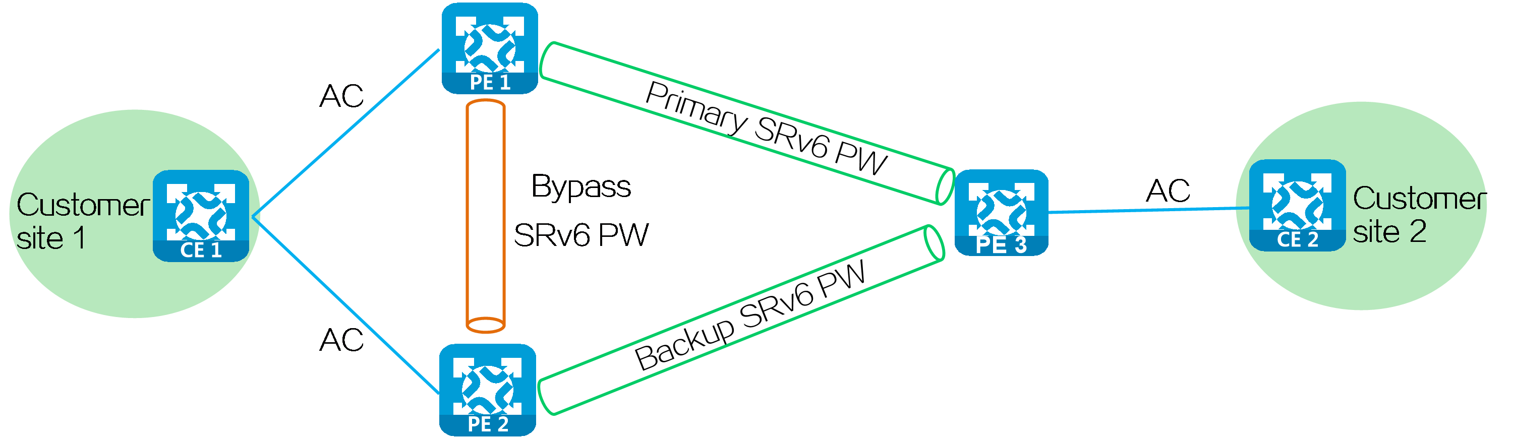
CE 1 is dual-homed to PE 1 and PE 2 through link aggregation or S-Trunk. CE 2 is single-homed to PE 3. You can establish SRv6 PWs in the network to implement interconnection between customer sites. You can deploy bypass SRv6 PW and primary and backup SRv6 PWs to minimize impact on the network caused by AC or SRv6 PW failures, improving network reliability and stability.
Figure50 Multi-homed + FRR networking
4.8 SRv6 and MPLS interworking
About SRv6 and MPLS interworking
With mature development of Internet, SRv6 and MPLS networks are gradually becoming representatives of efficient, reliable, and secure network solutions. However, in practical applications, due to the differences in routing information and packet encapsulation between the two networks, interoperability between SRv6 and MPLS networks has become an important issue to resolve.
Currently, there are two method to implement SRv6 and MPLS interworking: one is to deploy VPN instances on the network border device, and the other is to adopt the inter-AS Option B method without deploying VPN instances. The implementation principles of these two methods are different.
According to the different backbone network structures, SRv6 and MPLS interworking can be divided into the following types:
· Interworking between IP L3VPN SRv6 network and MPLS L3VPN network.
· Interworking between IP L3VPN SRv6 network and EVPN L3VPN network.
· Interworking between EVPN L3VPN SRv6 network and MPLS L3VPN network.
· Interworking between EVPN L3VPN SRv6 network and EVPN L3VPN network.
In summary, there are two interworking methods and four interworking types, totaling eight scenarios. When using the same interworking method, the implementations for the four types of network interworking are similar. The only difference lies in the BGP route types used to carry private network routing information. This document takes IP L3VPN over SRv6 interworking with MPLS L3VPN as an example to describe in details for two scenarios.
Comparison of interworking methods
Choose the interworking method based on a comprehensive consideration of the scenario conditions. The characteristics and advantages of the two methods are listed in the table below for your reference.
Table7 Comparison of SRv6 and MPLS interworking methods
|
VPN instance deployment on the border device |
Inter-AS Option B |
|
|
Characteristics |
Inter-AS is not required (inter-AS is also allowed). The network border device must reoriginate the received private network routes. |
Inter-AS is required. When the types of the BGP routes that carry private network routes on both sides of the networks are the same, the network border device does not need to reoriginate private network routes. |
|
Applicable scenarios |
The network border device has VPN instance deployment requirements. |
The network border device does not allow the deployment of VPN instances. |
|
Benefits |
· The network border device can collect private network routes from different sites and VPN instances into one VPN instance. It then assigns SRv6 SIDs to these private network routes within the same VPN instance before forwarding them to save SRv6 SID resources. · It is compatible with the HoVPN architecture to achieve SPE and UPE interconnection across different types of networks in the HoVPN architecture. |
· The network border device does not need to deploy VPN instances and can simply act as "transit stations" for private network routes, with low deployment difficulty. · Since there is no need to regenerate private network routes, the integrity of private network routing information can be maximally ensured when transmitting the private network routes. |
Interworking method: VPN instance deployment on the border device
Networking model
Figure51 Network diagram for deploying VPN instances on border devices
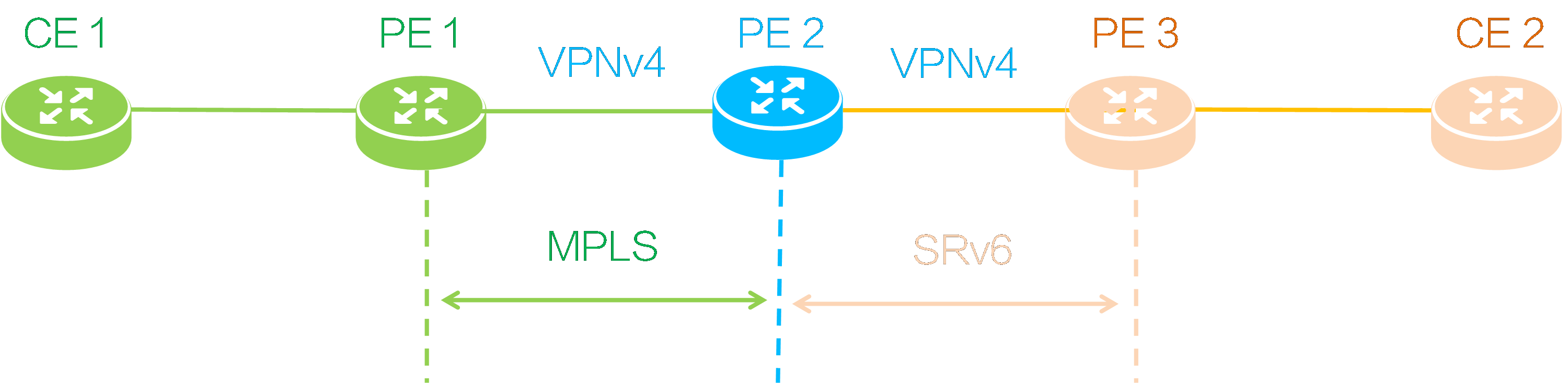
In this network, an MPLS L3VPN network is deployed between PE 1 and PE 2, establishing a BGP VPNv4 session. An IP L3VPN over SRv6 network is deployed between PE 2 and PE 3, establishing a BGP VPNv4 session. After deploying SRv6 and MPLS interworking, private network users connected to CE 1 and CE 2 can communicate with each other.
The SRv6 with MPLS interworking is mainly achieved at the border device (PE 2), and the interworking operating mechanisms include private network route advertisement and packet forwarding.
Private network route advertisement
CE 1 to CE 2 route advertisement
Figure52 Private network route advertisement
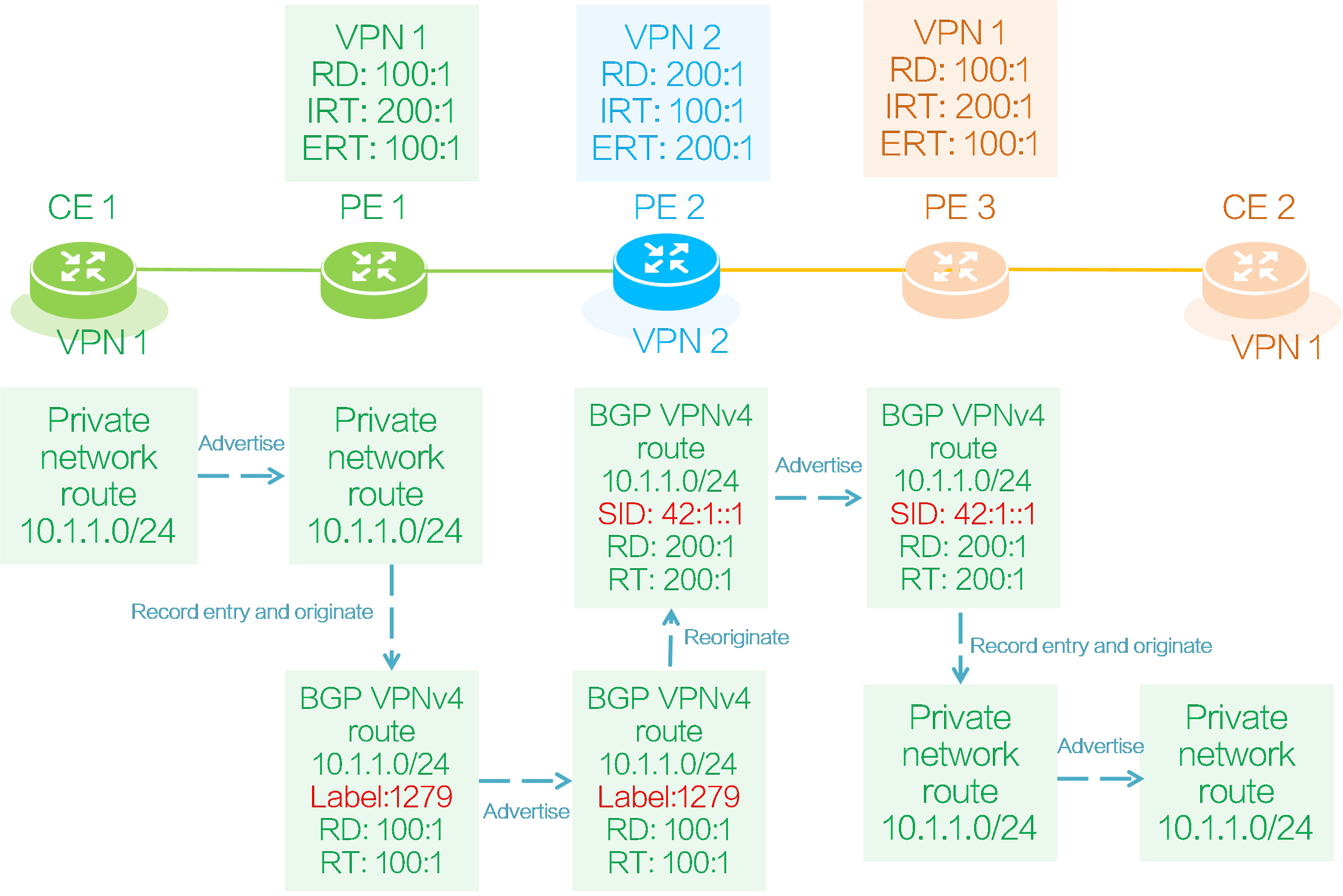
As shown in the figure above, both PE 1 and PE 2 deploy VPN instance 1 to connect CE 1 and CE 2. PE 2 deploys VPN instance 2. CE 1 sends a private network route to CE 2 as follows:
(1) CE 1 advertises its local private network route 10.1.1.0/24 to PE 1 through IGP, BGP, or static routing.
(2) PE 1 adds the received private network route to the IP routing table of VPN instance 1, and adds RD 100:1 and RT 100:1 attributes to the route to generate a BGP VPNv4 route.
(3) PE 1 assigns a private network label of 1279 to the BGP VPNv4 route, and then advertises the route to PE 2 through the BGP VPNv4 session. The VPN instance bound to private network label 1279 is VPN instance 1.
(4) The RT attribute carried in the BGP VPNv4 route 10.1.1.0/24 matches the locally configured IRT 100:1 of VPN instance 2 on PE 2, so PE 2 receives the route and adds it to the IP routing table of VPN instance 2.
(5) PE 2 reoriginates the BGP VPNv4 route 10.1.1.0/24 in VPN instance 2. The reoriginated BGP VPNv4 route 10.1.1.0/24 carries RD 200:1 and ERT 200:1 of VPN instance 2. Additionally, PE 2 assigns the route an SRv6 SID of 42:1::1 in VPN instance 2. (The SRv6 SID can be End.DT4 SID, End.DT6 SID, End.DT46 SID, End.DX4 SID, or End.EX6 SID. In this example, it is an End.DT4 SID.)
(6) PE 2 advertises the reoriginated BGP VPNv4 route 10.1.1.0/24 to PE 3.
(7) The RT attribute carried in the BGP VPNv4 route 10.1.1.0/24 matches the locally configured IRT attribute 200:1 of VPN instance 1 on PE 3, so PE 3 receives the route and adds it to the IP routing table of VPN instance 1.
(8) PE 3 advertises the private network route 10.1.1.0/24 of VPN instance 1 to CE 2 through IGP, BGP, or static routing.
The IP routing table entries formed on the devices in the backbone network during the private network route advertisement process are shown in the following table:
Table8 IP routes on backbone devices
|
Device Name |
Destination Address |
VPN instance |
Next Hop |
|
PE 1 |
10.1.1.0/24 |
VPN 1 |
CE 1 |
|
PE 2 |
10.1.1.0/24 |
VPN 2 |
Label forwarding path pointing to PE 1 |
|
PE 3 |
10.1.1.0/24 |
VPN 1 |
SRv6 tunnel pointing to PE 2 |
|
|
Locator subnet route advertisement
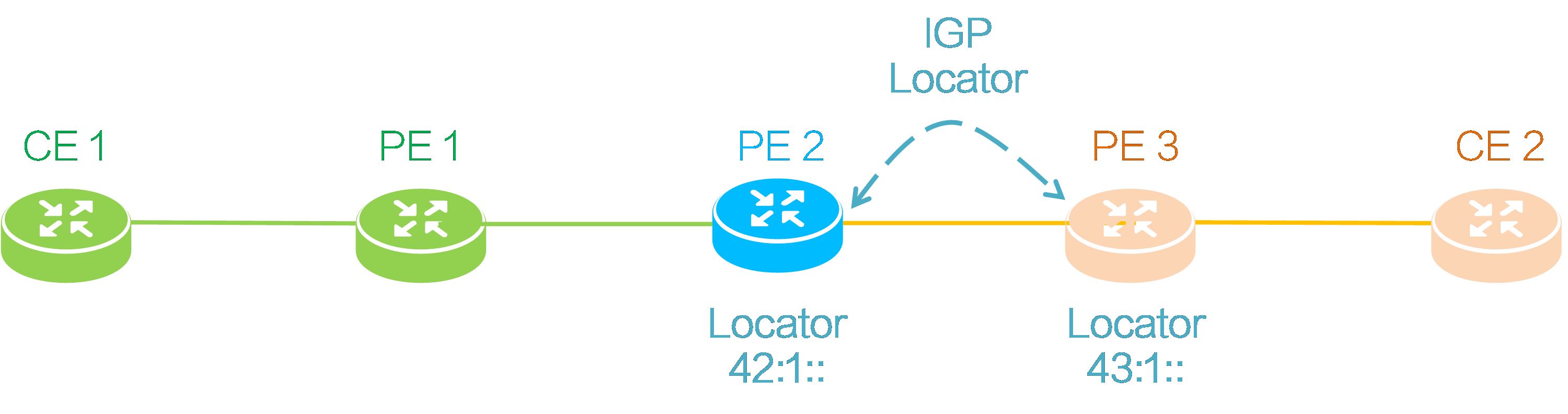
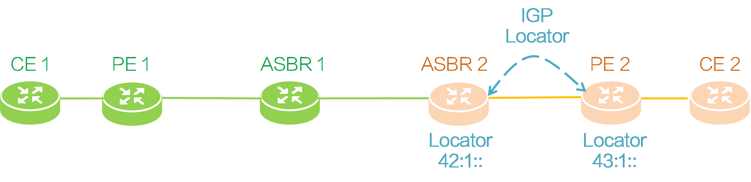
As shown in the figure below, PE 2 and PE 3 need to advertise their respective locator subnet route to each other through an IGP. The locator subnet route prefix advertised by PE 2 is 42:1::, and that advertised by PE 3 is 43:1::.
Figure53 Advertising locator subnet routes
Packet forwarding
CE 2 to CE 1 packet forwarding
Figure54 Packet forwarding
As shown in the above figure, taking the SRv6 BE forwarding mode as an example, CE 2 forwards a packet to CE 1 as follows:
(1) CE 2 encapsulates an IPv4 packet header for the private network data, with the source address as 20.1.1.1 and the destination address as 10.1.1.1, forming a private network packet. Then, it sends the packet to PE 3.
(2) PE 3 looks up the IP routing table of VPN instance 1 after receiving the private network packet and finds the route with the prefix 10.1.1.0/24. The SRv6 SID corresponding to this route is 42:1::1. PE 3 encapsulates an outer IPv6 header for the private network packet, with the destination IPv6 address as the SRv6 SID.
(3) According to the outer destination IPv6 address of the encapsulated packet, PE 3 searches the public IP routing table and finds the locator subnet route advertised by PE 2, and then sends the packet to PE 2 based on that route.
(4) PE 2 receives the packet and finds that the outer destination IPv6 address is the local End.DT4 SID. It decapsulates the outer IPv6 header of the packet and looks up the IP routing table in VPN instance 2 corresponding to End.DT4 SID 42:1::1. PE 2 finds the route with the prefix 10.1.1.0/24 from PE 1, and the corresponding private network label for this route is 1279. Therefore, PE 2 encapsulates the inner private network label 1279 and the outer public network label, and then forwards the packet along the label forwarding path to PE 1.
(5) After receiving the packet, PE 1 pops out the outer public network label, identifies that the packet belongs to VPN instance 1 based on the inner private network label 1279, and then searches the routing table in VPN instance 1. PE 1 finds the route from CE 1 with the prefix 10.1.1.0/24, and then pops all the labels and forwards the packet to CE 1 based on that route.
|
|
Interworking method: inter-AS option B
Networking model
Figure55 Inter-AS option B networking
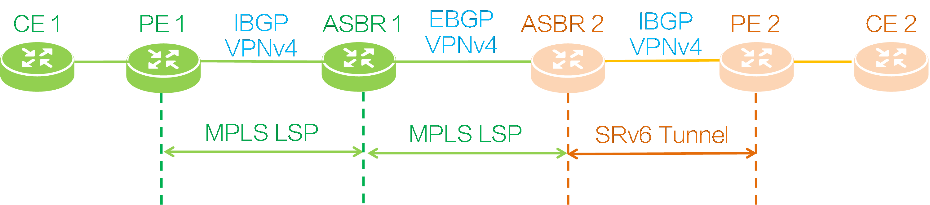
As shown in the figure above, deploy an MPLS L3VPN between PE 1 and ASBR 1, and establish IBGP VPNv4 session between them; deploy an MPLS L3VPN between ASBR 1 and ASBR 2, and establish EBGP VPNv4 session between them; deploy an IP L3VPN over SRv6 network between ASBR 2 and PE 2, and establish IBGP VPNv4 session between them. After SRv6 and MPLS interworking is deployed, private network users connected to CE 1 and CE 2 can communicate with each other.
End.T SID
End.T SIDs are required to achieve SRv6 and MPLS interworking by using inter-AS option B. The ASBR in the SRv6 network assigns and adds End.T SIDs to the private network routes from the MPLS network. The function of an End.T SID is removing the outer IPv6 header and looking up the IPv6 FIB table based on the End.T SID to forward packets.
Private network route advertisement
CE 1 to CE 2 route advertisement
Figure56 CE 1 to CE 2 route advertisement
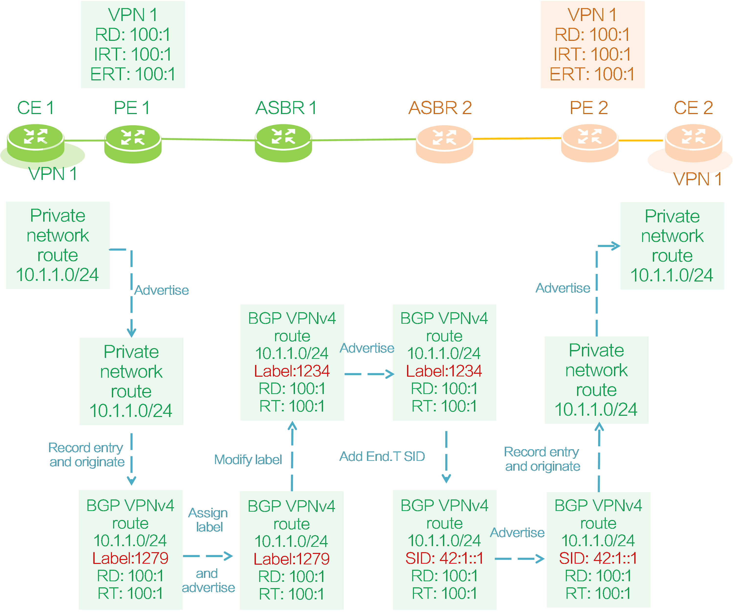
As shown in the figure above, both PE 1 and PE 2 deploy VPN instance 1 to connect CE 1 and CE 2. CE 1 advertises a private network route to CE 2 as follows:
(1) CE 1 advertises its local private network route 10.1.1.0/24 to PE 1 through IGP, BGP, or static routing.
(2) PE 1 adds the received private network route to the IP routing table of VPN instance 1, and adds RD 100:1 and RT 100:1 attributes to the route to generate a BGP VPNv4 route.
(3) PE 1 assigns a private network label 1279 to the route, and then advertises the route to ASBR 1 through the IBGP VPNv4 session. The VPN instance bound to private network label 1279 is VPN instance 1.
(4) ASBR 1 receives BGP VPNv4 route 10.1.1.0/24 advertised by PE 1, modifies the next hop of the route to its own IP address, and assigns a new private network label 1234 to the route to replace the original private network label 1279.
(5) ASBR 1 adds a mapping entry of BGP VPNv4 route 10.1.1.0/24 for the new and old labels in the local ILM table. If the incoming label is the new label 1234, it replaces the label with the old label 1279 and sends it to PE 1, as shown in the following diagram.
Table9 ASBR 1 label mapping
|
InLabel |
Operation |
SwapInfo |
Forwarding Info |
|
1234 |
SWAP |
1279 |
To PE 1 |
(6) ASBR 1 advertises the BGP VPNv4 route 10.1.1.0/24 with private network label 1234 to ASBR 2 through the EBGP VPNv4 session.
(7) After receiving the BGP VPNv4 route from ASBR 1, ASBR 2 modifies the next hop of the route to its own IP address, assigns the End.T SID 42:1::1 to the route, and generates an IPv6 FIB entry as shown in the following diagram. End.T SID 42:1::1 carried by the route is associated with the private network label 1234 carried by the route in the IPv6 FIB entry. According to this label and the NHLFE entry corresponding to private network label 1234, the packet with destination address End.T SID 42:1::1 will be encapsulated with the private network label 1234 on ASBR 2 and sent to ASBR 1.
Table10 ASBR IPv6 FIB entry
|
Destination |
Label |
|
42:1::1 |
1234 |
(8) ASBR 2 advertises BGP VPNv4 route 10.1.1.0/24 with End.T SID 42:1::1 to PE 2 through the IBGP VPNv4 session.
(9) The RT attribute carried in the BGP VPNv4 route 10.1.1.0/24 matches the IRT attribute 100:1 configured for local VPN instance 1 on PE 2, so PE 2 receives the route and adds it to the IP routing table of VPN instance 1.
(10) PE 2 advertises the private network route 10.1.1.0/24 of VPN instance 1 to CE 2 through IGP, BGP, or static routing.
CE 2 to CE 1 route advertisement
Figure57 CE 2 to CE 1 route advertisement
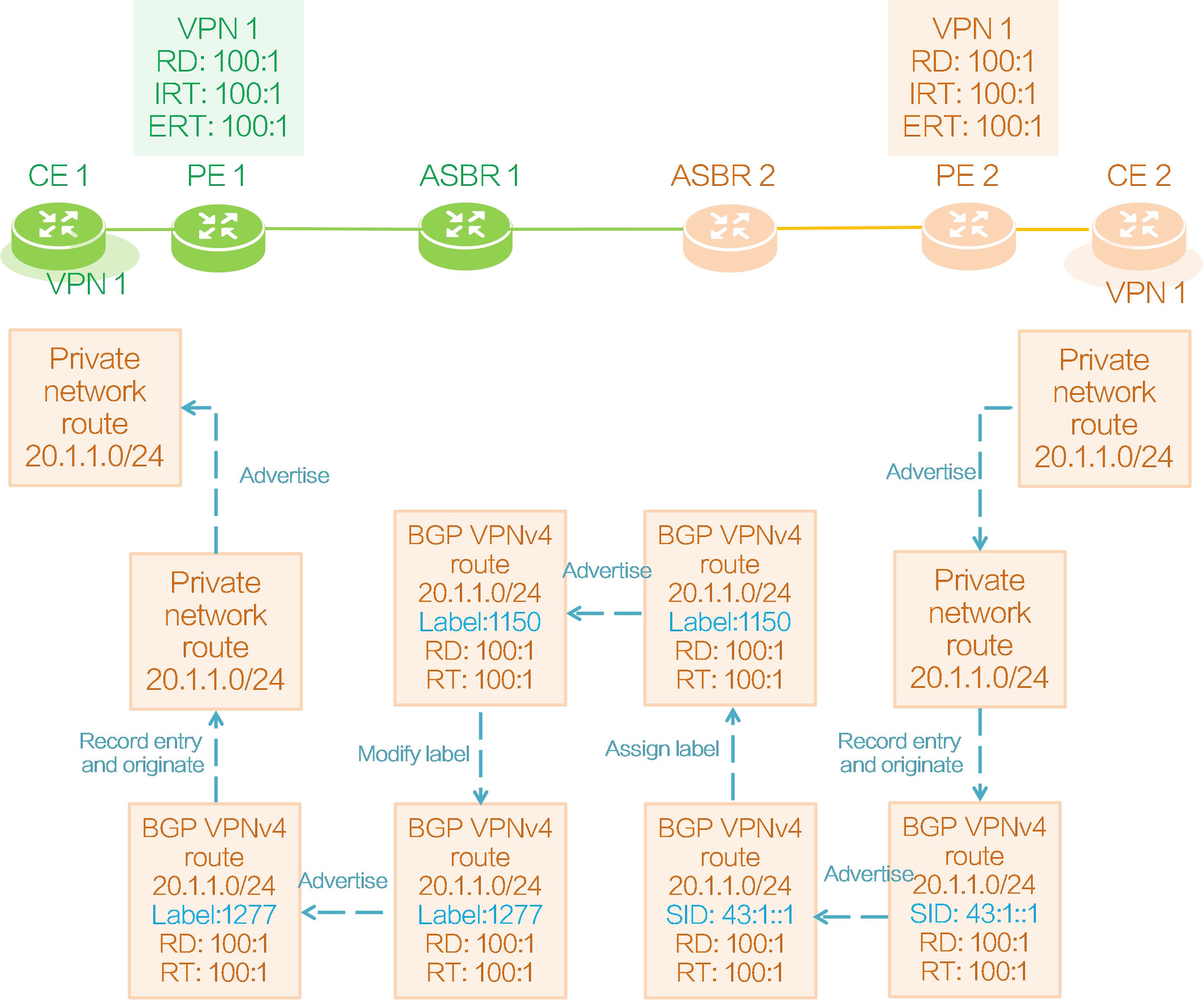
As shown in the above figure, the route of CE 2 is advertised to CE 1 in the following process:
(1) CE 2 advertises its local private network route 20.1.1.0/24 to PE 2 through IGP, BGP, or static routing.
(2) Upon receiving the private network route, PE 2 adds it to the IP routing table of VPN instance 1, adds RD 100:1 and RT 100:1 to it, and reoriginates a BGP VPNv4 route.
(3) PE 2 requests SRv6 SID 43:1::1 for the reoriginated route in VPN instance 1, and then advertises the route to ASBR 2 through the IBGP VPNv4 session. (The SRv6 SID can be End.DT4 SID, End.DT6 SID, End.DT46 SID, End.DX4 SID, or End.EX6 SID. In this example, the SRv6 SID is End.DT4 SID.)
(4) ASBR 2 receives BGP VPNv4 route 20.1.1.0/24 advertised by PE 2, modifies the next hop of the route to its own IP address, assigns private network label 1150 to the route, and adds the following mapping entry for the private network label and SRv6 SID in the local ILM table. Through the ILM entry, ASBR 2 associates the End.DT4 SID 43:1::1 carried by the route with the private network label 1150 assigned to the route. The packet carrying the private network label 1150 will be encapsulated with the destination IPv6 address End.DT4 SID 43:1::1 on ASBR 2 and sent to PE 2.
Table11 ASBR 2 label mapping
|
InLabel |
Operation |
SwapInfo |
Forwarding Info |
|
1150 |
SWAP |
43:1:1 |
Sent to PE 2 |
(5) ASBR 2 advertises BGP VPNv4 route 20.1.1.0/24 with private network label 1150 to ASBR 1 through the EBGP VPNv4 session.
(6) ASBR 1 modifies the next hop of the BGP VPNv4 route received from ASBR 2 to its own IP address and assigns a new private network label 1277 to the route instead of the original label 1150.
(7) ASBR 1 adds a mapping entry for BGP VPNv4 route 20.1.1.0/24 with the new and old labels in the local ILM table. If the incoming label is the new label 1277, it replaces it with the old label 1150 and sends it to ASBR 2.
Table12 ASBR 1 label mapping
|
InLabel |
Operation |
SwapInfo |
Forwarding Info |
|
1277 |
SWAP |
1150 |
Sent to ASBR 2 |
(8) ASBR 1 advertises the BGP VPNv4 route 20.1.1.0/24 with the private network label 1277 to PE 1 through the IBGP VPNv4 session.
(9) The RT attribute carried in BGP VPNv4 route 20.1.1.0/24 matches IRT 100:1 configured for local VPN instance 1 on PE 1, so PE 1 receives the route, redistributes it into VPN instance 1, and adds it to the IP routing table of VPN instance 1.
(10) PE 2 advertises the private network route 20.1.1.0/24 of VPN instance 1 to CE 1 through IGP, BGP, or static routing.
Locator subnet route advertisement
As shown in the figure below, ASBR 2 and PE 2 need to advertise their respective locator subnet route information to each other through IGP. The locator route prefix advertised by ASBR 2 is 42:1::, and that advertised by PE 2 is 43:1::.
Figure58 Locator subnet route advertisement
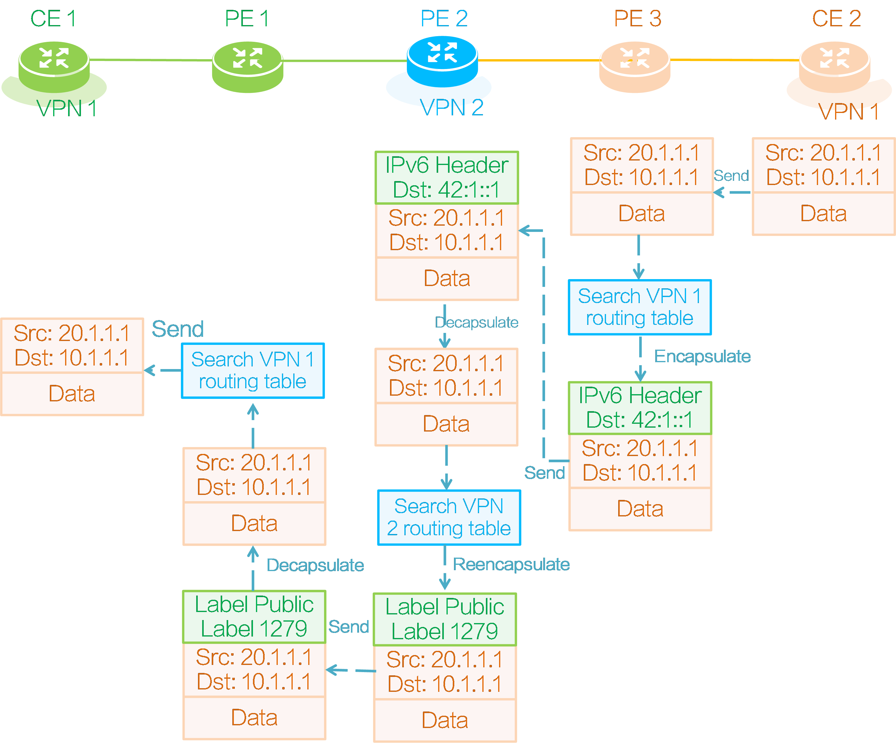
Packet forwarding
CE 1 to CE 2 packet forwarding
Figure59 Packet forwarding
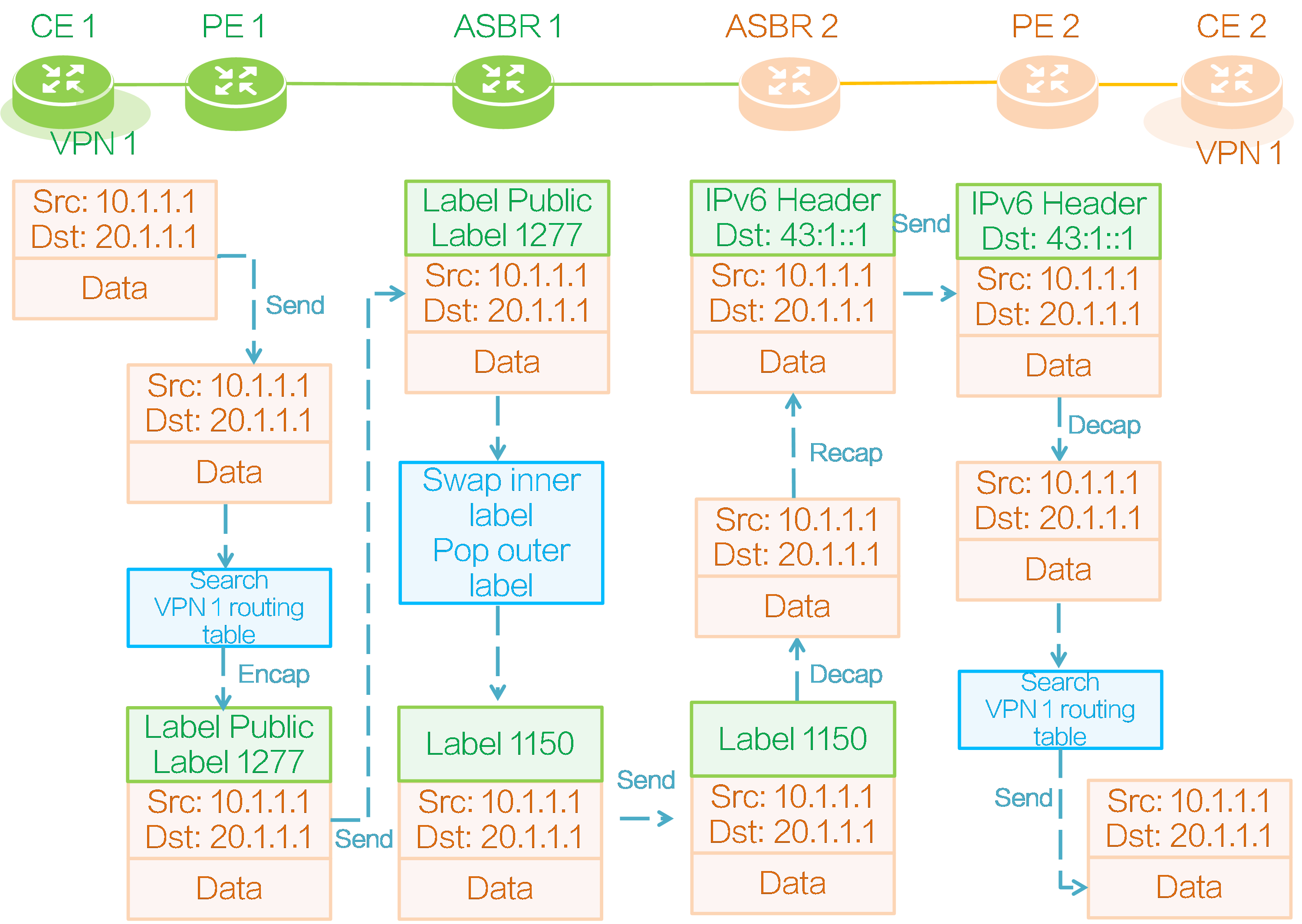
As shown in the above figure, taking SRv6 BE forwarding mode as an example, a private network packet is forwarded from CE 1 to CE 2 is as follows:
(1) CE 1 encapsulates an IPv4 header for the private network data, with source address 10.1.1.1 and destination address 20.1.1.1, and sends the private network packet to PE 1.
(2) PE 1 looks up the IP routing table of VPN instance 1 after receiving the private network packet and finds a route with prefix 20.1.1.0/24. The private network label associated with this route is 1277. Therefore, PE 1 encapsulates the inner private network label 1277 and the outer public network label for the packet, and then forwards the packet along the label forwarding path to ASBR 1.
(3) After receiving the private network packet, ASBR 1 pops the outer public network label and replaces private network label 1277 with private network label 1150 according to the ILM entry corresponding to private network label 1277. Because ASBR 1 and ASBR 2 only have a single-hop label LSP, ASBR 1 directly forwards the private network packet with private network label 1150 to ASBR 2.
(4) After receiving the private network packet, based on the ILM entry corresponding to private network label 1150, ASBR 2 pops the private network label 1150 and re-encapsulates it with an outer IPv6 header. The destination IPv6 address of the encapsulated outer IPv6 header is End.DT4 SID 43:1::1 mapped to private network label 1150.
(5) ASBR 2 looks up the public IP routing table based on the outer destination IPv6 address of the encapsulated packet, finds the locator subnet route advertised by PE 2, and then sends the packet to PE 2 based on that route.
(6) PE 2 receives the packet and finds that the outer destination IPv6 address is the local End.DT4 SID. It then decapsulates the outer IPv6 header of the packet and looks up the IP routing table in VPN instance 1 corresponding to End.DT4 SID 43:1::1. PE 2 finds the route with prefix 10.1.1.0/24 from CE 2, and then forwards the packet to CE 2 based on that route.
CE 2 to CE 1 packet forwarding
Figure60 Packet forwarding
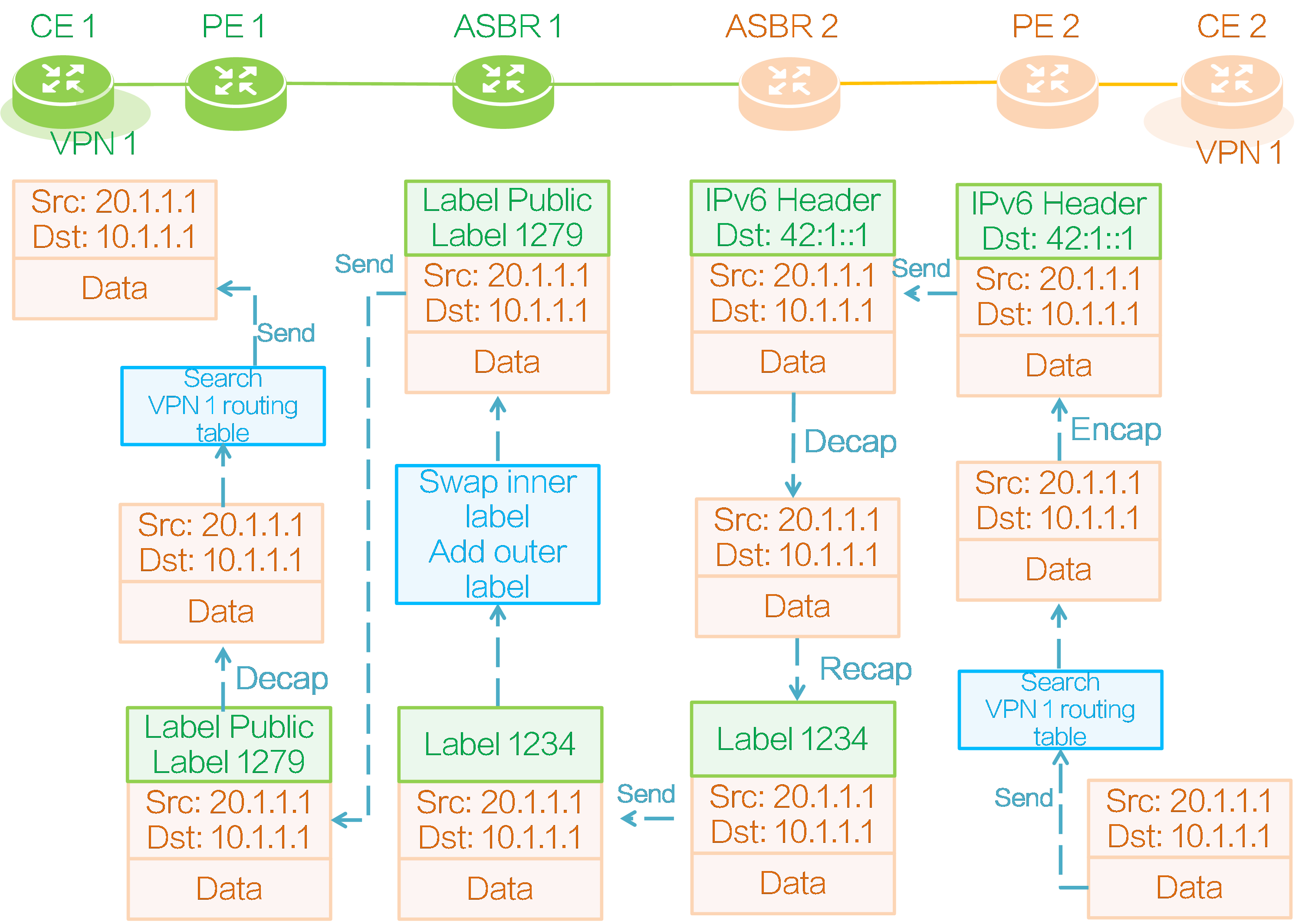
As shown in the above figure, taking the SRv6 BE forwarding mode as an example, CE 2 forwards a packet to CE 1 as follows:
(1) CE 2 encapsulates an IPv4 packet header for the private network data, with the source address as 20.1.1.1 and the destination address as 10.1.1.1, and then sends the private network packet to PE 2.
(2) Upon receiving the private network packet, PE 2 looks up the IP routing table of VPN instance 1, locates the route with prefix 10.1.1.0/24, identifies SRv6 SID 42:1::1 for that route, and encapsulates an outer IPv6 header for the packet, with the SRv6 SID as the destination IPv6 address in the encapsulated outer IPv6 packet header.
(3) PE 2 looks up the public IP routing table based on the outer destination IPv6 address of the encapsulated packet, finds the locator route advertised by ASBR 2, and then sends the packet to ASBR 2 based on the route.
(4) ASBR 2 receives the packet and finds that the outer destination IPv6 address is the local End.T SID. Then it decapsulates the outer IPv6 header of the packet and looks up the IPv6 FIB table locally. According to the found IPv6 FIB entry, ASBR 2 encapsulates the packet with inner private network label 1234. Because ASBR 1 and ASBR 2 only have a single-hop LSP, ASBR 2 directly forwards the private network packet with private network label 1234 to ASBR 1.
(5) After receiving the packet, ASBR 1 replaces the private network label corresponding to ILM table entry 1234 with private network label 1279, and adds an outer public network label to the packet. Then, it forwards the packet along the LSP to PE 1.
(6) After receiving the packet, PE 1 pops out the outer public network label, identifies that the packet belongs to VPN instance 1 based on the inner private network label 1279, and then searches the routing table in VPN instance 1. PE 1 finds the route with prefix 10.1.1.0/24 from CE 1, and then pops all the labels and forwards the packet to CE 1 based on that route.
4.9 SRv6 high availability
Introduction
In an SRv6 network, packet loss might occur when a link or node fails or recovers from a failure. To ensure stable forwarding of service traffic in the SRv6 network, SRv6 provides high availability measures to avoid long interruptions of service traffic and improve network quality.
Figure61 SRv6 high availability
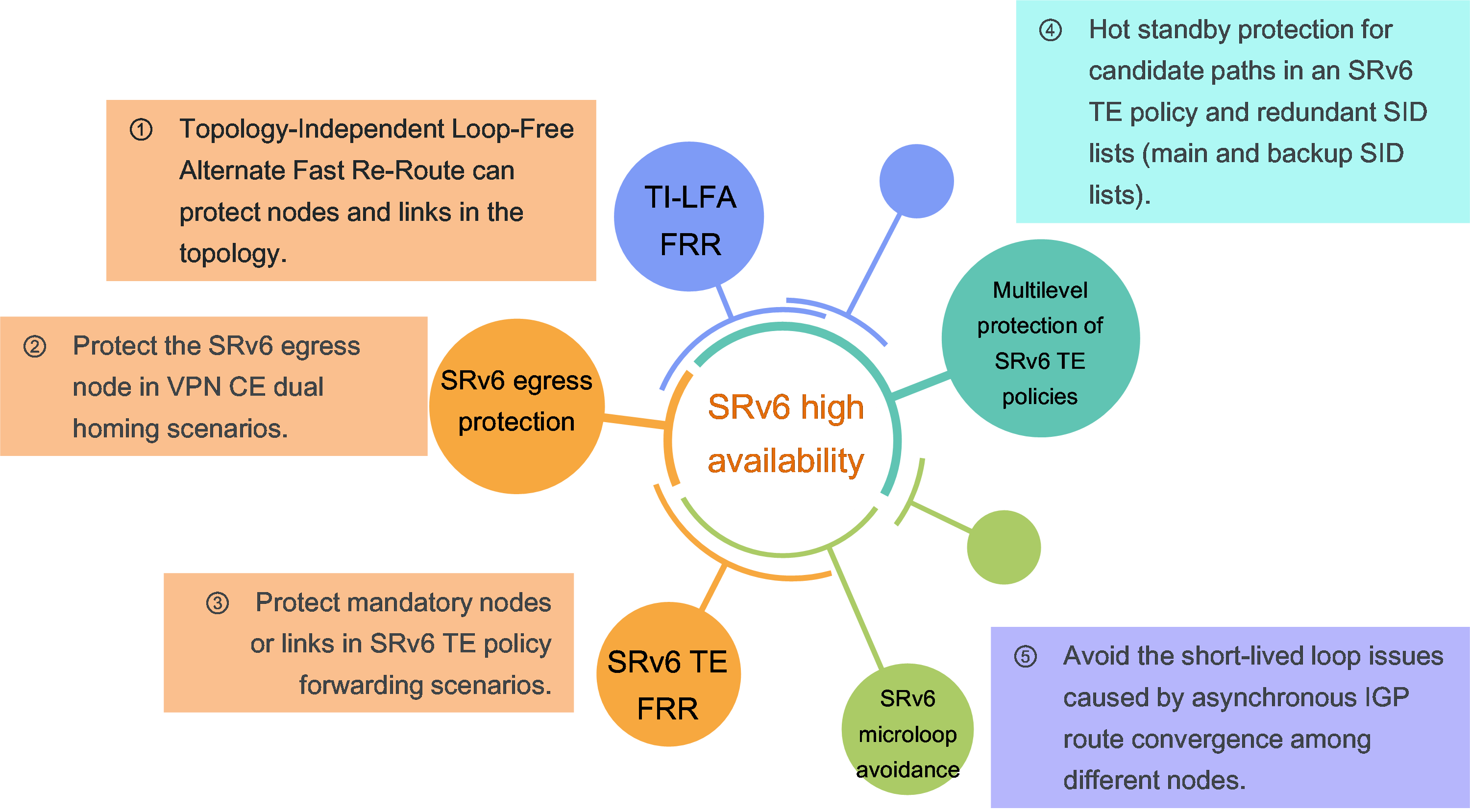
An SRv6 network provides the following high availability mechanisms:
· Node link-level protection—Includes TI-LFA FRR, SRv6 TE FRR, and SRv6 egress protection.
· Instantaneous loop protection—Includes SRv6 microloop avoidance.
· Path-level protection—Includes multilevel protection of SRv6 TE policies.
Node link-level protection
TI-LFA FRR
As shown in the figure below, the target flow reaches the destination node along the optimal forwarding path. You can select a link or node on the optimal forwarding path as a protected link or node and enable TI-LFA FRR on the upstream node directly connected to the protected link or the upstream neighbor node of the protected node. This upstream node is called the Point of Local Repair (PLR). TI-LFA FRR uses the following process to protect links and nodes:
(1) The PLR runs the TI-LFA FRR algorithm and automatically calculates and generates a strict explicit path based on SRv6 SIDs. This strict explicit path does not pass through the protected links or nodes and acts as a backup protection path for FRR. This path is loaded into the routing table.
(2) When a protected link is interrupted or a protected node fails, and the IGP routing protocol in the network has not finished route convergence, the PLR cannot forward traffic through the optimal forwarding path. Instead, it quickly switches over the traffic to the TI-LFA FRR backup path for forwarding. This mechanism avoids traffic loss during the routing convergence process.
(3) After the IGP routing protocol finishes route convergence, the PLR will forward traffic along the converged path.
TI-LFA FRR can calculate backup paths as long as the network has suboptimal paths. However, since the faulty nodes and links are unpredictable, you need to enable TI-LFA FRR on multiple nodes.
Figure62 TI-LFA FRR protection
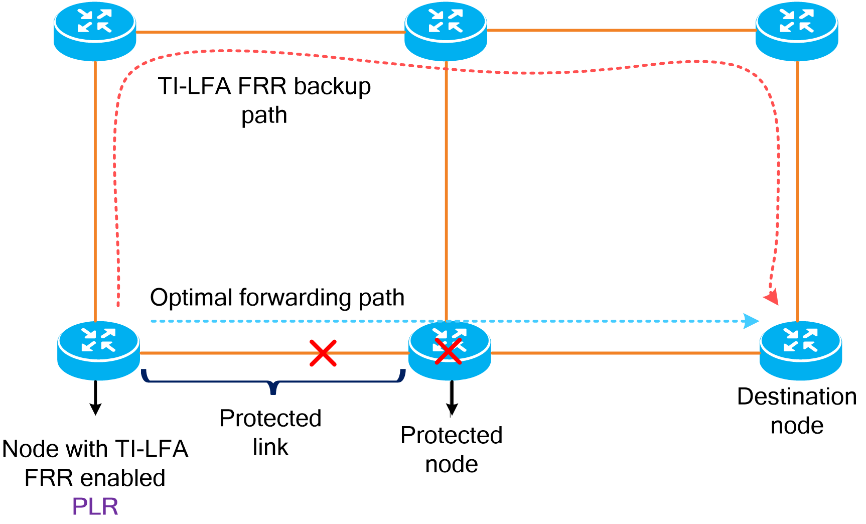
SRv6 TE FRR
As shown in the figure below, node E is a mandatory node for the SRv6 TE policy from ingress node A to egress node F. That is, the SID lists of all candidate paths for the SRv6 TE policy must include the SID of node E. In this case, you must protect node E. For the upstream neighbor node (node B) of node E, the destination address of packets is node E. If only TI-LFA FRR is enabled on node B when node E fails, node B only calculates a backup path for reaching node E without bypassing it. In this case, you must also enable SRv6 TE FRR on node B, so that node B will ignore the destination address of the packets, bypass node E, and reach the egress node (node F). Node B, which has enabled SRv6 TE FRR, is referred to as the proxy forwarding node. If an SRv6 TE policy has multiple mandatory nodes or links, you can enable SRv6 TE FRR on multiple nodes to deal with unpredictable failures.
Figure63 SRv6 TE FRR protection
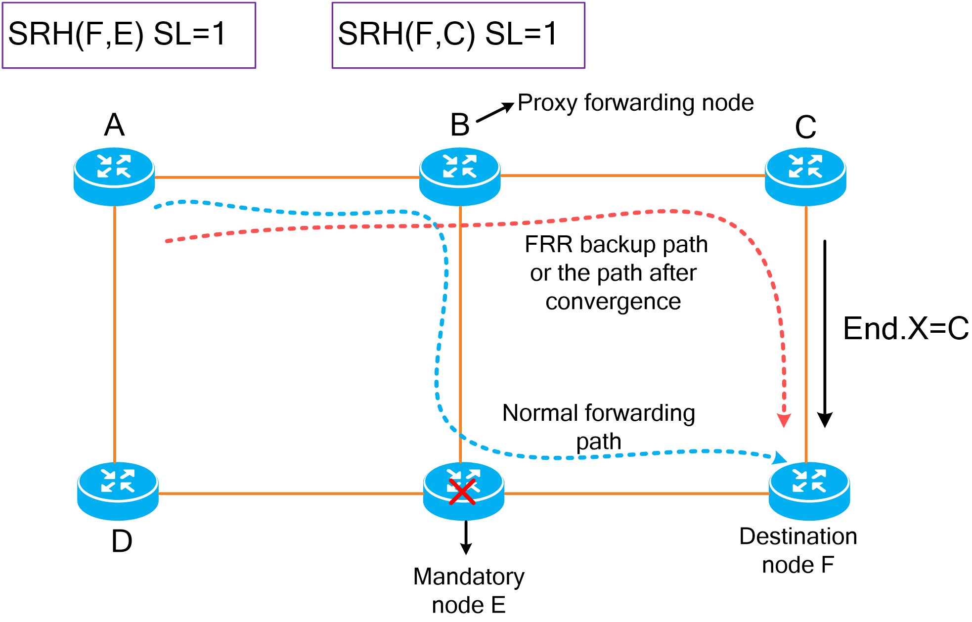
The process to bypass mandatory node E for SRv6 TE FRR protection is as follows.
(1) Node B, the proxy forwarding node, detects that the next hop (node E) for packets is unreachable, the SID of node E is the destination address of the packets, and the SL value in the packets is greater than 0. In this case, node B decreases the SL value by 1 and copies the next SID (the SID of node F) to the destination address field in the outer IPv6 header. Since the SL value becomes 0, node B removes the SRH extension header from the packets and looks up the routing table for the destination address to forward the packets to node F.
(2) When the routing protocol has not finished route convergence, the primary next hop for the destination address (F) on node B is still the faulty node (node E). In this case, node B forwards the packets from node C to node F along the TI-LFA FRR backup path.
(3) After route convergence, proxy forwarding can also be triggered on node B to bypass node E and forward traffic to the destination node along the optimal forwarding path after convergence based on the destination address (F).
SRv6 egress protection
In the IPv4 L3VPN over SRv6 network as shown in the figure below, node C acts as the egress node of the SRv6 tunnel. The CE belongs to VPN instance A and is dual-homed to nodes C and F. The normal forwarding path for VPN traffic is node A, node B, node C, and the CE in sequence. To protect the SRv6 locator of egress node C, you can configure an End.M SID (mirror SID) on node F (the CE is dual homed to this node and node C).
Figure64 SRv6 egress protection
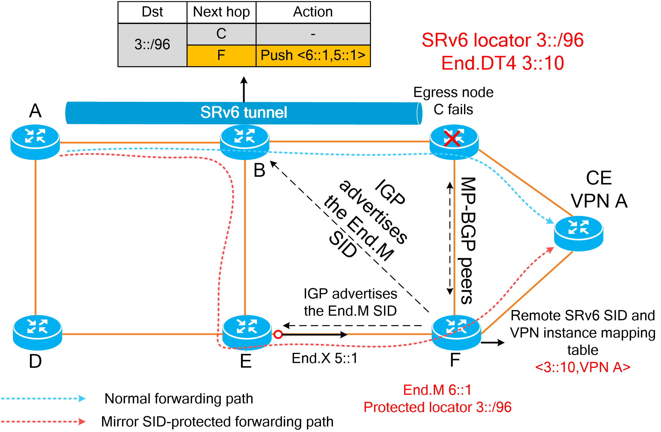
The process of egress protection is as follows:
(1) Egress node C advertises the VPNv4 route with its End.DT4 SID, RD, and route targets to node F. The End.DT4 SID matches the protected locator of the End.M SID, and node F generates a mapping entry of <3::10, VPN A>.
(2) Node F advertises the End.M SID and its protected locator to IGP peers. As the directly connected peer of the protected locator, node B calculates and generates a TI-LFA FRR backup path destined for End.M SID (mirror SID).
(3) When egress node C fails, node B detects that the next hop (node C) is unreachable, and it quickly switches over traffic to the TI-LFA FRR backup path for forwarding. Node B encapsulates the original SRv6 packets with a new IPv6 header and optionally an SRH extension header. The SRH header carries the SID list of the strict explicit path. This enables traffic to bypass egress node C and reach node F.
(4) After receiving the packets, egress node F decapsulates the outer IPv6 header and SRH extension header based on the End.M SID, and it finds that the destination address of the inner packets is 3::10. By looking up the remote SRv6 SID and VPN instance mapping table, node F identifies that the packets belong to VPN instance A and forwards the packets to the CE.
Instantaneous loop protection
SRv6 microloop avoidance
During network failure or recovery, the IGP recalculates and converges routes. Due to different convergence speeds of nodes in the network, different nodes might experience asynchronous IGP convergence, leading to short-lived loops in traffic between these nodes. After the IGP finishes route convergence on all nodes, these short-lived loops will disappear automatically. These short-lived loops are known as microloops. Microloops might cause network packet loss, delay, and jitter.
SRv6 microloop avoidance enables a node to calculate a strict explicit path that contains a list of SRv6 SIDs. After the node completes convergence in case of topology changes, it starts a timer and forwards traffic according to the strict explicit path before the timer expires. This mechanism avoids microloops caused by asynchronous convergence of other nodes.
The faulty nodes are unpredictable, so you need to enable SRv6 microloop avoidance on multiple network nodes.
Microloop avoidance after a network failure
Figure65 Diagram for microloop avoidance after a network failure
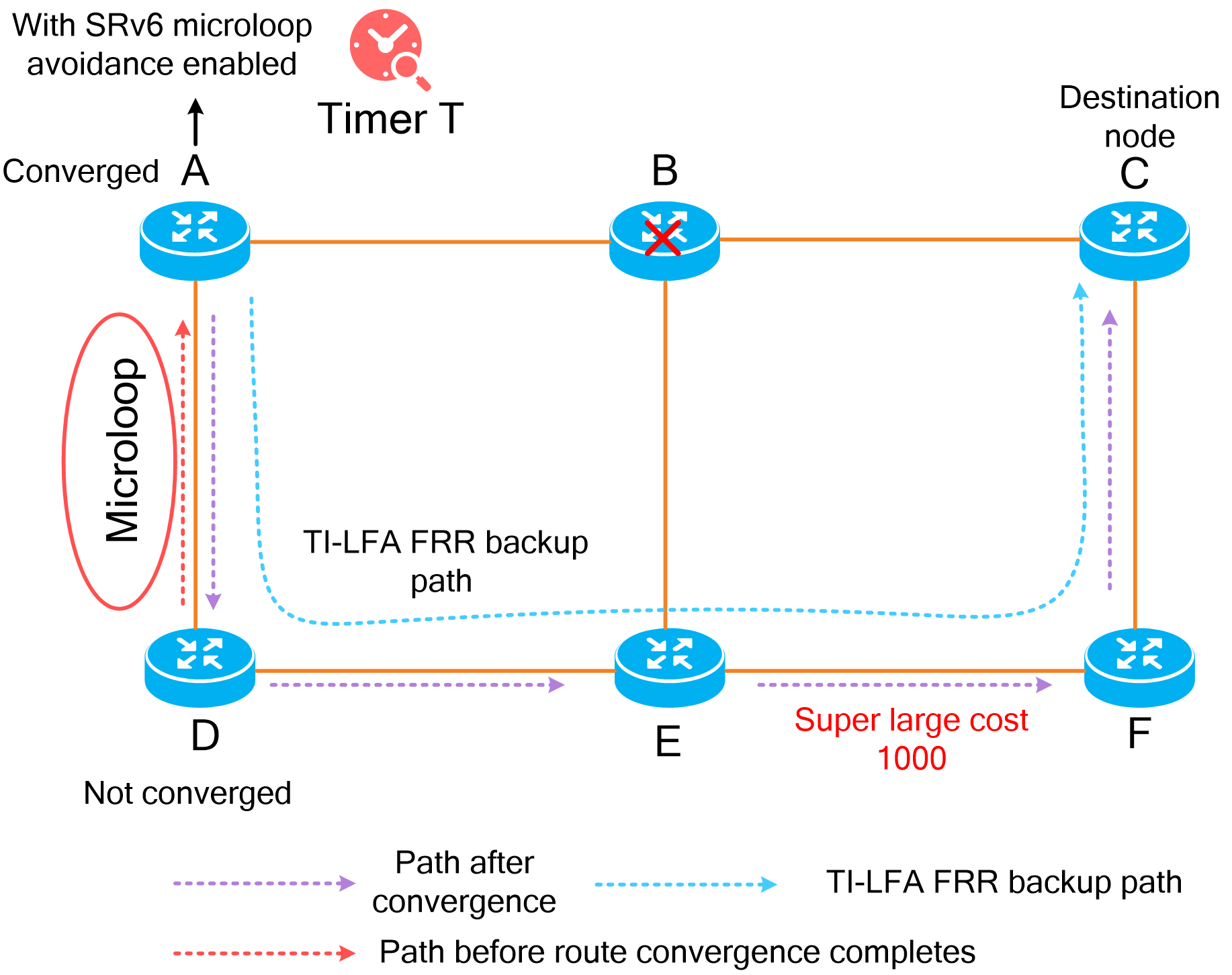
When node B fails, traffic from node A to destination node C is forwarded through the TI-LFA FRR backup path. If the IGP of node A has completed route convergence but the IGP of node D has not completed route convergence, node A exits the TI-LFA FRR forwarding process and directly uses the address of node C as the destination address to forward the traffic to node D. Because node D has not completed route convergence, it redirects the traffic back to node A. In this case, a microloop exists between nodes A and D.
To resolve this issue, enable SRv6 microloop avoidance on node A. With this feature enabled, node A retains the TI-LFA FRR backup path and starts timer T after IGP convergence. Before the timer expires, node A always forwards traffic along the TI-LFA FRR backup path. After the timer expires, the node will switch over the traffic to the converged path. This mechanism avoids microloop issues after a network failure. Microloop avoidance after a network failure must be used in conjunction with TI-LFA FRR on nodes.
Microloop avoidance after a failure recovery
Figure66 Diagram for microloop avoidance after a failure recovery
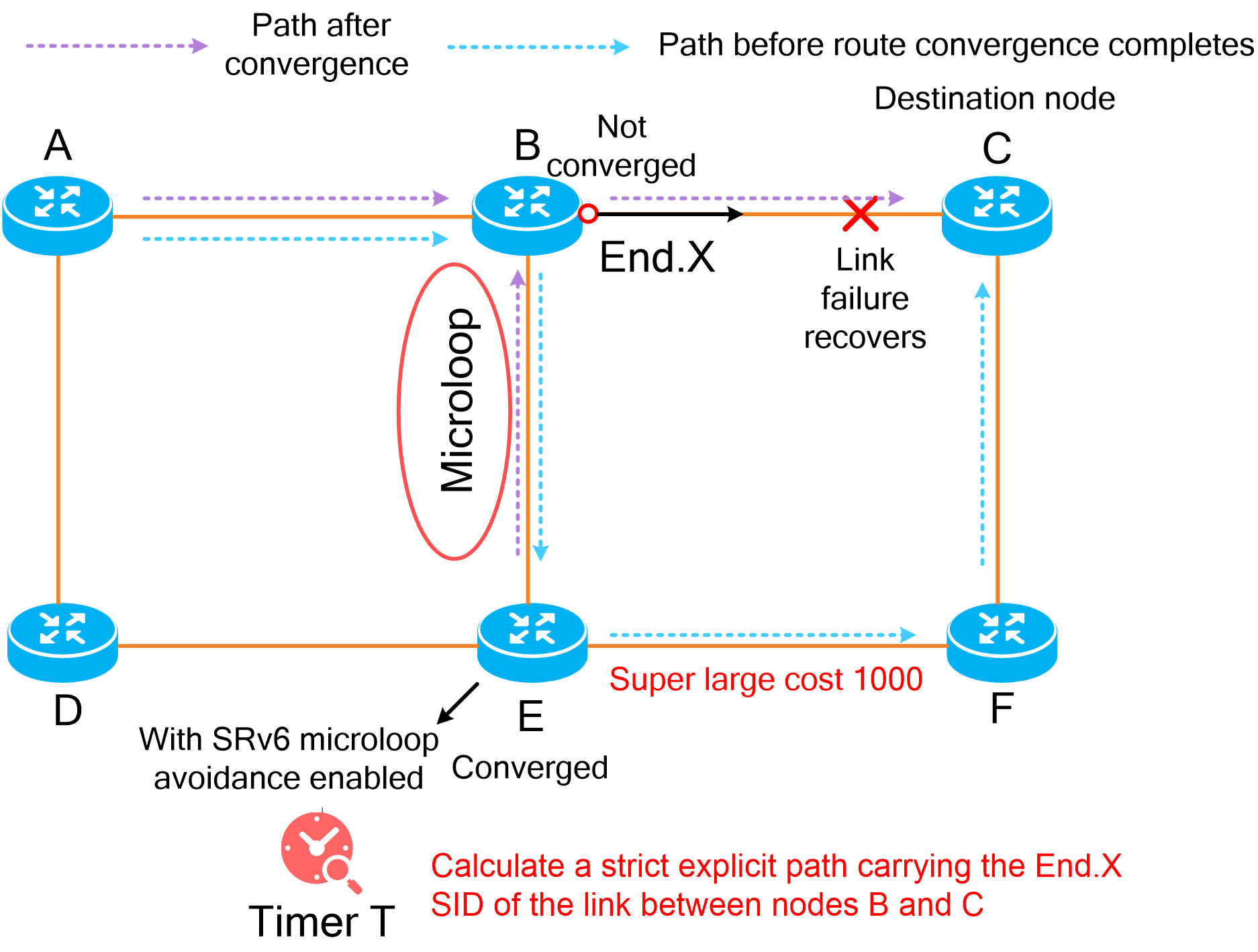
If the IGP of node E has completed route convergence but the IGP of node B has not completed route convergence after the link between nodes B and C recovers, the traffic from node A to node C is still forwarded along path B -> E -> F -> C. Node E returns the traffic back to node B. In this case, a microloop exists between nodes B and E.
To resolve this issue, enable SRv6 microloop avoidance on node E. With this feature enabled, node E calculates a strict explicit path carrying the End.X SID of the link between nodes B and C during IGP convergence and starts timer T. Before the timer expires, traffic is forwarded along the strict explicit path to avoid microloops occurred after a failure recovery. Because microloop avoidance after a failure recovery cannot identify which link recovers, the strict explicit path might include the End.X SIDs of multiple links.
Path-level protection
SRv6 TE policy multilevel protection
As shown in the figure below, an SRv6 TE policy is deployed between ingress node A and egress node C. The SRv6 TE policy supports multiple protection mechanisms with candidate paths and SID lists.
The SRv6 TE policy has three candidate paths x, y, and z, which support multilevel hot standby.
(1) If all SID lists of the main candidate path (path x) are faulty, the primary backup candidate path (path y) is used.
(2) If all SID lists of the primary backup candidate path are faulty, the secondary backup candidate path (path z) is used.
In the same candidate path, the traffic is load balanced across the paths represented by multiple SID lists. In addition, you can specify a backup SID list for an SID list.
For example, when the forwarding path of SID list a fails, traffic will be switched over to backup SID list e for forwarding. When the backup SID list also fails, the traffic of candidate path x is only forwarded through SID list b. When SID lists a, b, and e are all malfunctioning, the traffic is then switched over to the backup candidate path (path y) for forwarding.
To provide multilevel path protection capabilities for an SRv6 TE policy and ensure high availability of SRv6 TE policy traffic forwarding, you can specify a backup SID list for each SID list, share traffic load among multiple SID lists, and configure hot standby protection for candidate paths.
Figure67 SRv6 TE policy multilevel protection
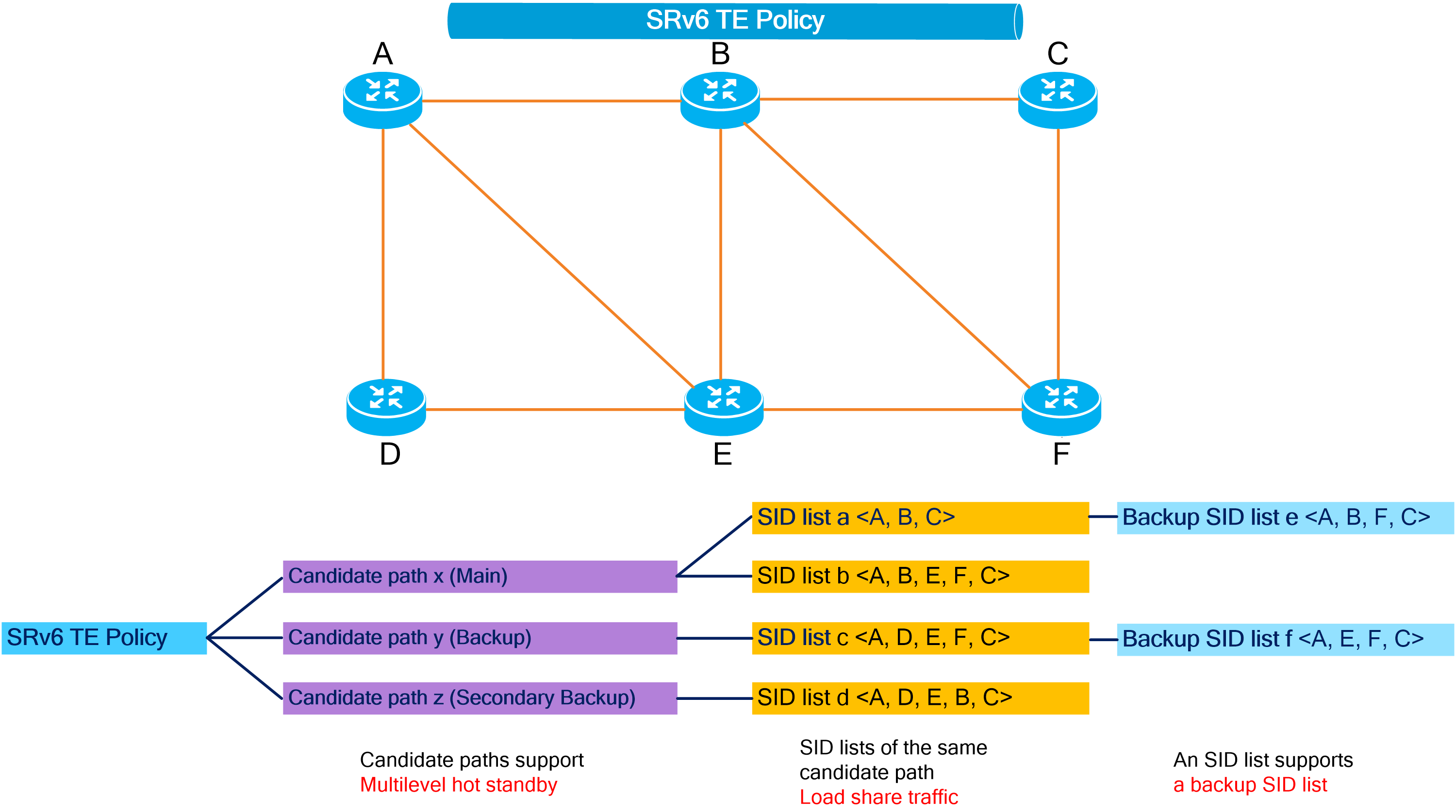
SRv6 high availability summary
For any network, faults are unpredictable, but network faults can be simply classified as follows:
· Single point of failure—At a certain moment, a single link or node in the network fails.
· Multiple points of failure—At a certain moment, multiple nodes and links in the network malfunction at the same time.
Different SRv6 high availability mechanisms are applicable to different fault scenarios.
· Protection for single points of failure—TI-LFA FRR, SRv6 TE FRR, and SRv6 egress protection are all used for recovery of specific single points of failure, and the combination of them can provide protection for all types of nodes or links in SRv6 tunnels. However, for multiple points of failures, you must deploy TI-LFA FRR, SRv6 TE FRR, and SRv6 egress protection on multiple nodes along the forwarding path. The configuration and deployment is not simple enough.
¡ The TI-LFA FRR mechanism mainly repairs single points of failure for non-mandatory SRv6 transit nodes or links. The TI-LFA FRR algorithm plays a key role in high availability mechanisms such as SRv6 TE FRR, SRv6 egress protection, and SRv6 microloop avoidance. The algorithm is the foundation of SRv6 high availability mechanisms.
¡ The SRv6 TE FRR mechanism repairs single points of failure for mandatory SRv6 endpoint nodes or links in SRv6 TE policy network scenarios, filling the gaps left by TI-LFA FRR in protecting mandatory nodes or links.
¡ The SRv6 egress protection mechanism fixes single points of failure for the SRv6 tunnel egress in VPN over SRv6 scenarios. This mechanism is also a supplement to TI-LFA FRR.
· Protection for multiple points of failure—With the multilevel protection capabilities of an SRv6 TE policy, you can easily deploy protection for the entire forwarding path. However, in SRv6 BE network scenarios or in scenarios where the SRv6 TE policy in use only has one candidate path and SID list, you must also configure TI-LFA FRR, SRv6 TE FRR, and SRv6 egress protection.
· Protection for issues derived from faults—Typically, when deploying TI-LFA FRR protection for single points of failure, you must also deploy SRv6 microloop avoidance to avoid microloop issues derived from faults.
Figure68 Using different SRv6 high availability mechanisms in different fault scenarios
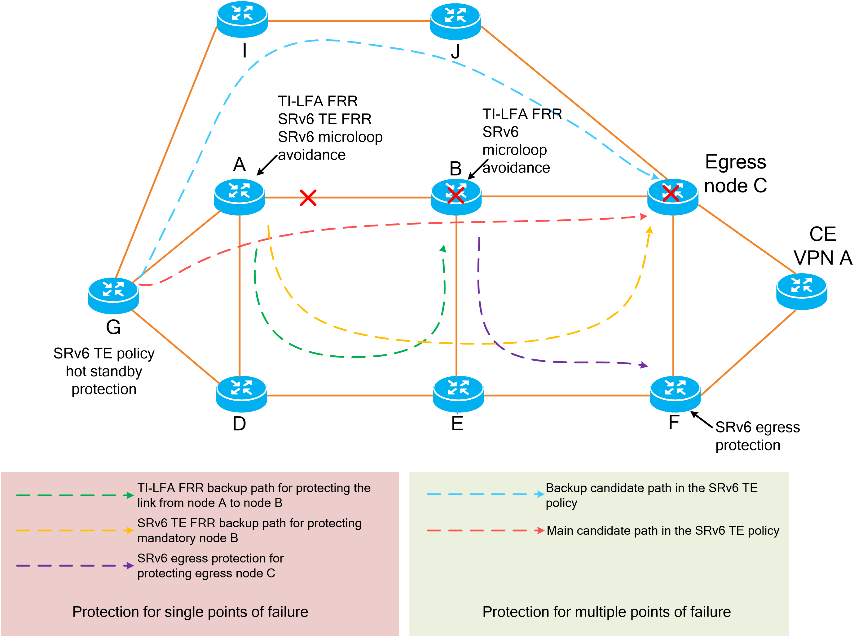
4.10 G-SRv6
Technical background
In an SRv6 TE policy scenario, the administrator must add the 128-bit SRv6 SIDs of SRv6 nodes on the packet forwarding path into the SID list of the SRv6 TE policy. If the packet forwarding path is long, a large number of SRv6 SIDs will be added to the SID list of the SRv6 TE policy. This greatly increases the size of the SRv6 packet header, resulting in low device forwarding efficiency and increased processing delay. The situation might be worse in a scenario that spans across multiple ASs where a much greater number of end-to-end SRv6 SIDs exist.
Figure69 SRv6 SIDs in an SRv6 TE policy network
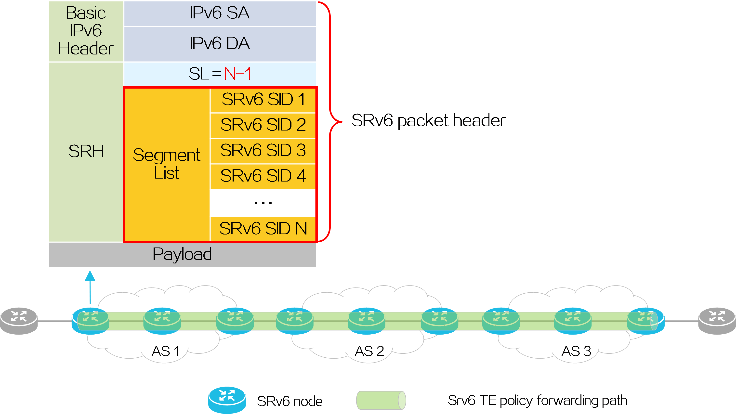
Generalized SRv6 (G-SRv6) encapsulates shorter SRv6 SIDs (G-SIDs) in the segment list of SRH by compressing the 128-bit SRv6 SIDs. This reduces the size of the SRv6 packet header and improves the efficiency for forwarding SRv6 packets. In addition, G-SRv6 supports both 128-bit SRv6 SIDs and G-SIDs in a segment list.
About G-SRv6
Typically, an address space is reserved for SRv6 SID allocation in an SRv6 subnet. This address space is called an SID space. In the SRv6 subnet, all SIDs are allocated from the SID space. The SIDs have the same prefix (common prefix). The SID common prefix is redundant information in the SRH.
G-SRv6 removes the common prefix and carries only the variable portion of SRv6 SIDs (G-SIDs) in the segment list, effectively reducing the SRv6 packet header size. To forward a packet according to routing table lookup, SRv6 replaces the destination IP address of the packet with the combination of the G-SID and common prefix in the segment list of the SRH.
With the compression efficiency and network scale taken into consideration, the ideal length of SRv6 SIDs is 32 bits after compression through G-SRv6.
Benefits
· Good compatibility
G-SRv6 supports the hybrid deployment of 32-bit G-SIDs and 128-bit SRv6 SIDs, enabling smooth network upgrade.
· High compression efficiency
Using 32-bit compression improves compression efficiency and the compressed SIDs are consistent with the current IPv4 address length, making it easy for hardware processing.
· Flexible networking options
G-SRv6 supports compression of SIDs within an AS domain and across AS domains, facilitating creation of compressed paths across multiple AS domains.
G-SID compression methods
128-bit SRv6 SID format
An SRv6 SID is in the format of IPv6 address.
Figure70 128-bit G-SID format
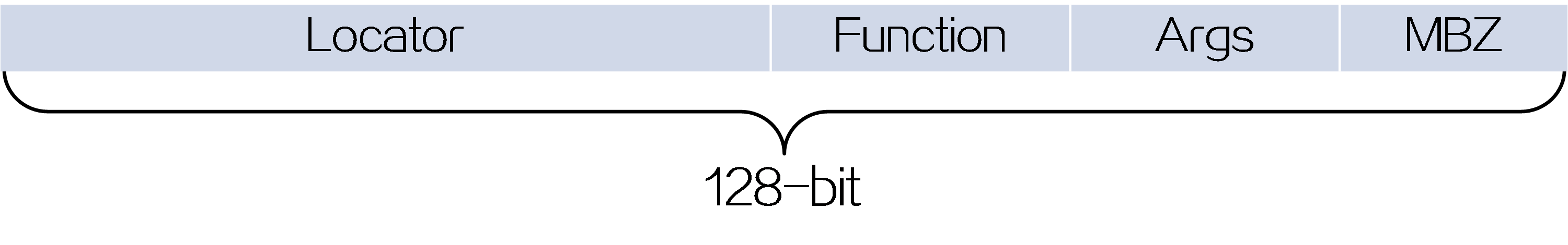
An SRv6 SID contains the Locator, Function, Arguments, and Must be zero (MBZ) portions.
· Locator—Identifies the network segment of the SID. The locator of an SRv6 SID must be unique in the SR domain.
· Function—Contains an opcode that identifies the network function of an SID. An SR node will execute the function in the SRv6 SID Function field of an SRv6 packet after it receives that SRv6 packet.
· Arguments—Defines flow and service parameters for SRv6 packets.
· MBZ—When the total number of bits in the Locator, Function, and Arguments portions is less than 128 bits, the remaining bits are padded with 0s.
Figure71 Locator portion
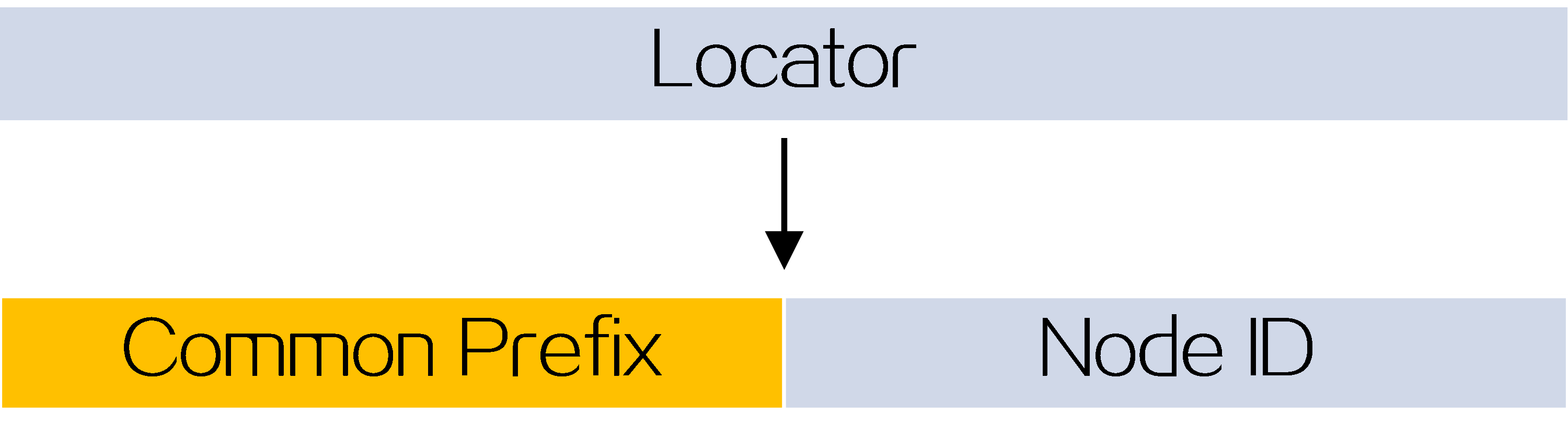
The locator portion of an SRv6 SID contains the Common Prefix and Node ID portions. The Common Prefix portion represents the address of the common prefix. The Node ID portion identifies a node. G-SRv6 can compress all SIDs with the same common prefix into 32-bit G-SIDs.
32-bit G-SID format
A 32-bit G-SID contains the Node ID and Function portions of a 128-bit SRv6 SID.
A 128-bit SRv6 SID is formed by the Common Prefix portion, a 32-bit G-SID, and the 0 (Args&MBZ) portion.
Figure72 32-bit G-SID format
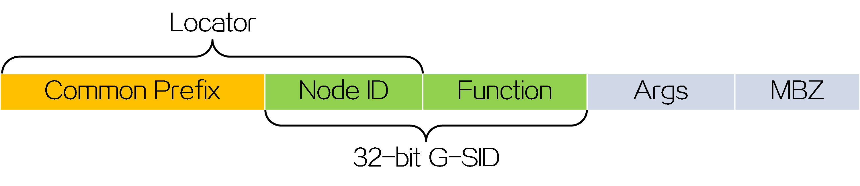
When deploying a G-SID, administrators must plan the length of the locator portion, common prefix, and the length of the Args portion in advance. As shown in the figure below, the length of the locator portion is 64, the common prefix is 10:20:30::/48, and the length of the Args portion is 16. The total length of the three portions is 96 bits. Therefore, the length of the MBZ portion is 128-96=32 bits.
Figure73 32-bit G-SID format length
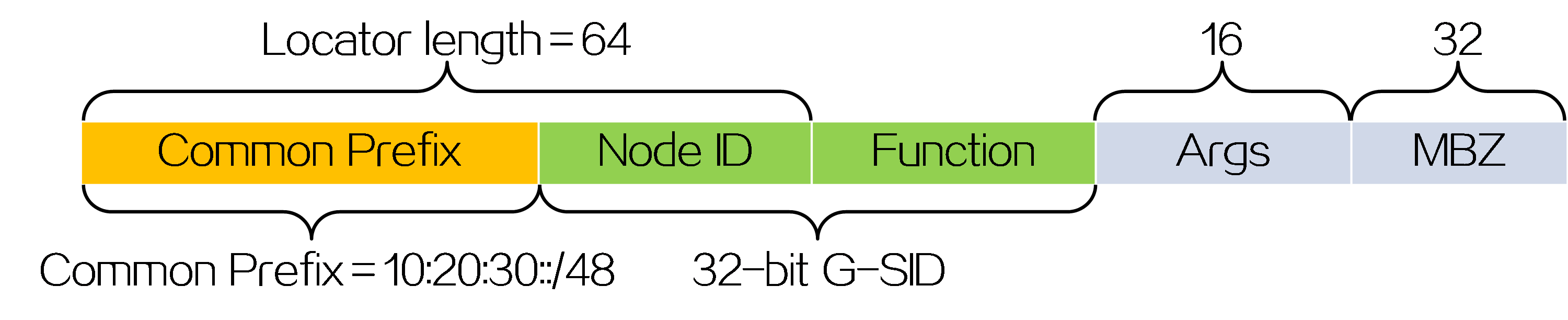
Based on the length of each field, the SRv6 SIDs within the following range must be compressed into G-SIDs:
· The start value is 10:20:30:0:1:: which means the lowest bit in the G-SID is 1.
· The end value is 10:20:30:FFFF:FFFF::, which means all bits in the G-SID are 1.
G-SRv6 packet format
G-SRv6 can encapsulate both G-SIDs and 128-bit SRv6 SIDs in the segment list of the SRH. It must encapsulate four G-SIDs in a group to the original location of a 128-bit SRv6 SID. If the location contains fewer than four G-SIDs (less than 128 bits), G-SRv6 pads the remaining bits with 0s. Multiple consecutive G-SIDs form a compressed path, called a G-SID list. A G-SID list can contain one or more groups of G-SIDs.
The G-SIDs in the segment list are arranged as follows:
(1) The SRv6 SID before the G-SID list is a 128-bit SRv6 SID with the COC flag, indicating that the next SID is a 32-bit G-SID.
(2) Except the last G-SID, all G-SIDs in the G-SID list must carry the COC flag to indicate that the next SID is a 32-bit G-SID.
(3) The last G-SID in the G-SID list must be a 32-bit G-SID without the COC flag, indicating that the next SID is a 128-bit SRv6 SID.
|
|
Figure74 G-SRv6 packet format
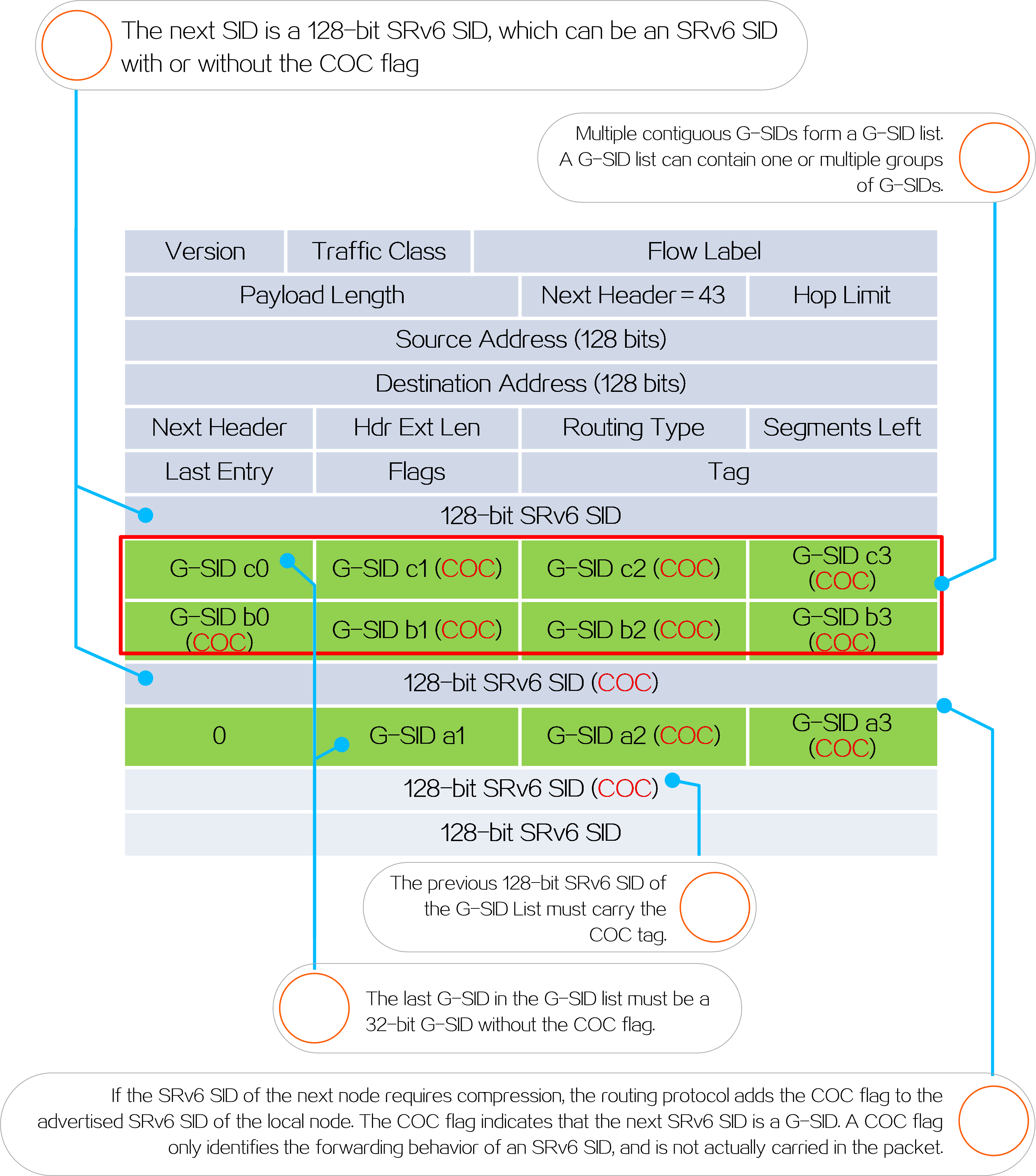
As shown in Figure 10, G-SRv6 combines the G-SID and Common Prefix in the segment list to form a new destination address.
· Common Prefix—Common prefix address manually configured by the administrator.
· G-SID—Compressed 32-bit SID obtained from the SRH.
· SID Index (SI)—Index that identifies a G-SID in a group of G-SIDs. This field is the least significant two bits of the destination IPv6 address. The value range is 0 to 3. The SI value decreases by 1 at each node that performs SID compression. If the SI value becomes 0, the SL value decreases by 1. In a group of G-SIDs in the segment list, the G-SIDs are arranged from left to right based on SI values. The SI value is 0 for the leftmost G-SID, and is 3 for the rightmost G-SID.
Figure75 G-SID arrangement
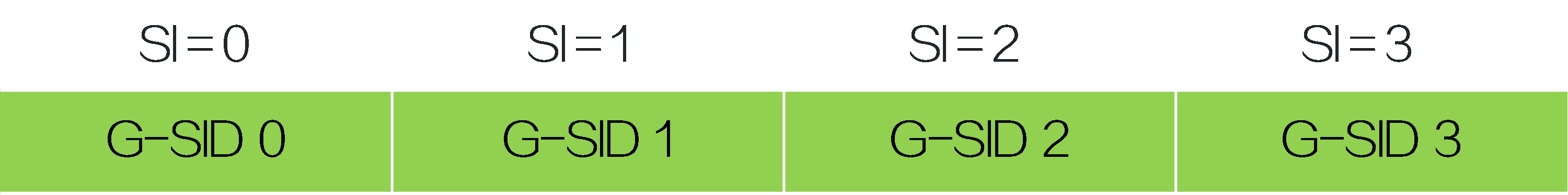
· 0—If the total length of the Common Prefix, G-SID, and SI portions is less than 128 bits, the deficient bits are padded with 0s before the SI portion.
Suppose the following conditions exist:
¡ The Common Prefix deployed on the SRv6 node is A:0:0:0::/64.
¡ The G-SID in the SRv6 packet is 1:1.
¡ The SI value associated with the G-SID is 3.
Figure76 The deficient bits are 0
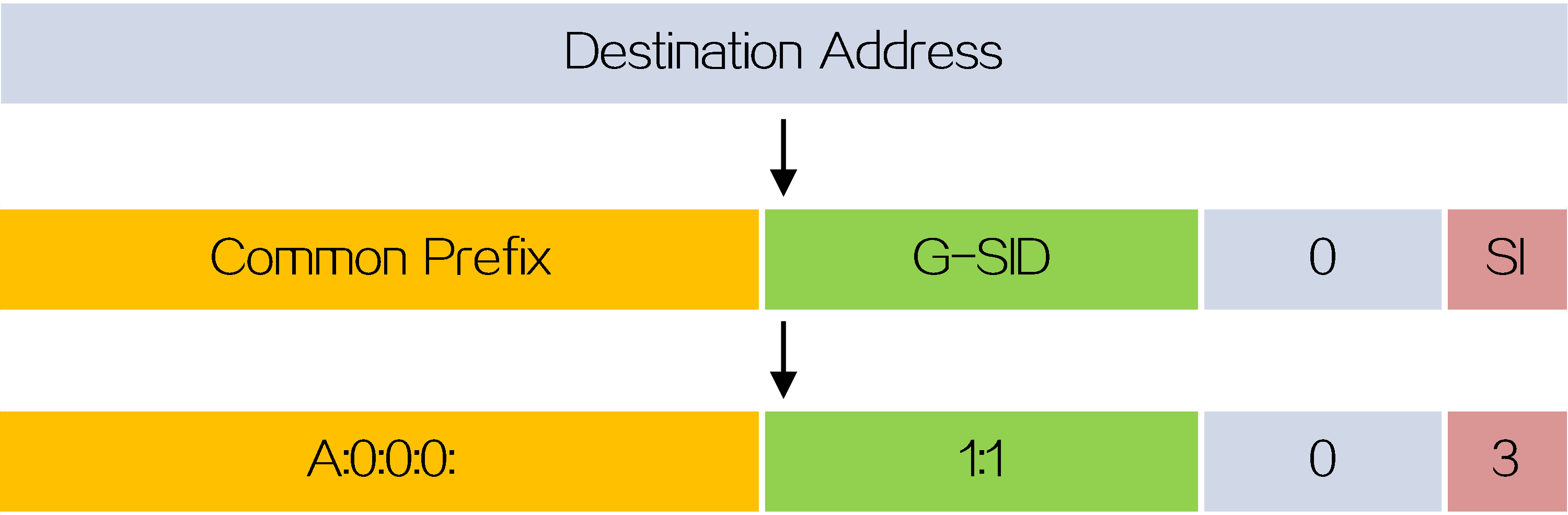
Upon receiving the G-SRv6 packet, the SRv6 node calculates the destination address for the packet as follows:
· If the destination address of the packet is a 128-bit SRv6 SID with the COC flag in the segment list, the next SID is a G-SID. The device decreases the SI value by 1 and searches for the G-SID group corresponding to [SI-1]. Then, the device calculates the destination address based on the 32-bit G-SID identified by SI value 3.
· If the destination address of the packet is a 32-bit SRv6 SID with the COC flag in the segment list, the next SID is a G-SID.
¡ If the SI value is larger than 0, the device decreases the SI value by 1 and searches for the G-SID group corresponding to SL value of the packet. Then, the device calculates the destination address based on the 32-bit G-SID identified by [SI-1].
¡ If the SI value is equal to 0, the device decreases the SL value by 1, resets the SI value to 3, and searches for the G-SID group corresponding to the SL value of the packet. Then, the device calculates the destination address based on the 32-bit G-SID identified by SI value 3.
Application scenarios
To reduce the overhead of SRv6 packet headers in an inter-domain SRv6 TE Policy networking environment, G-SRv6 can be deployed within the domain to compress SRv6 SIDs. As shown in the figure below, taking IPv4 L3VPN over SRv6 TE Policy as an example, different G-SIDs with different common prefixes are deployed in different ASs to reduce the length of the Segment List in the packet and improve device forwarding efficiency.
Figure77 G-SRv6 networking
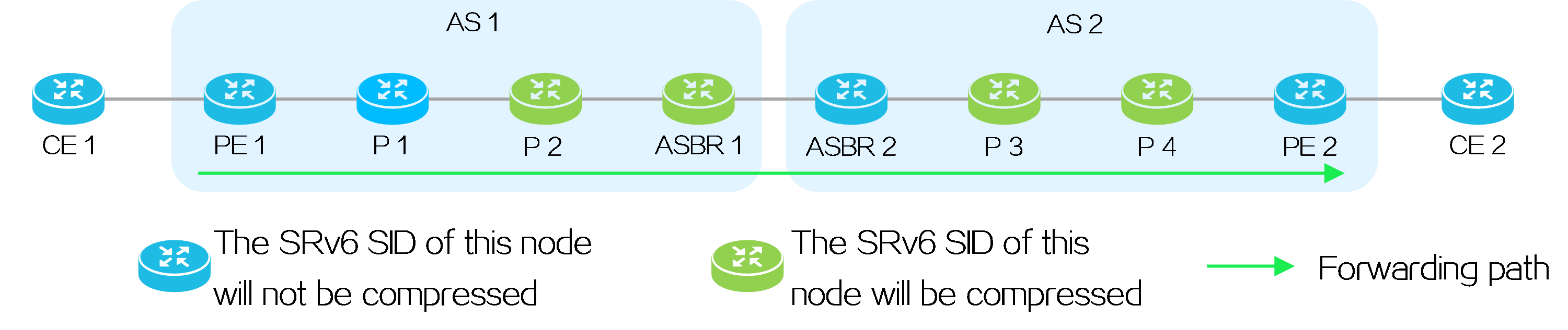
Network planning
PE 1 acts as the source node of the SRv6 TE policy. The End.X SID does not need to be added to the SID list of the SRv6 TE policy. To compress the SRv6 SIDs of other nodes within the AS, P1's SRv6 SID must carry the COC flag.
Table13 SRv6 SID planning for each AS
|
AS |
Common Prefix |
G-SID Length |
Args Length |
MBZ Length |
|
AS 1 |
A:0:0:0::/64 |
32 |
32 |
0 |
|
AS 2 |
B:0:0:0::/64 |
32 |
32 |
0 |
Table14 SRv6 SIDs in each AS
|
AS |
Device name |
SRv6 SID |
Remarks |
Whether compressed |
|
AS 1 |
PE 1 |
A:0:0:0:10:1:: |
End.X SID, not added to the SID list |
No |
|
P 1 |
A:0:0:0:1:1:: |
End.X SID that carries the COC tag |
No |
|
|
P 2 |
A:0:0:0:2:1:: |
End.X SID that carries the COC tag |
Yes |
|
|
ASBR 1 |
A:0:0:0:20:2:: |
End.X SID without the COC tag |
Yes |
|
|
AS 2 |
ASBR 2 |
B:0:0:0:30:1:: |
End.X SID that carries the COC tag |
No |
|
P 3 |
B:0:0:0:3:1:: |
End.X SID that carries the COC tag |
Yes |
|
|
P 4 |
B:0:0:0:4:2:: |
End.X SID without the COC tag |
Yes |
|
|
PE 2 |
B:0:0:0:40:1::2 |
End.DT4 SID assigned to private routes For more information about End.DT4 SIDs, see "L3VPN over SRv6 BE." |
No |
Create an SRv6 TE Policy between PE 1 and PE 2. The Segment List is encoded starting from the last segment of the path. The SID list is <A:0:0:0:1:1::, A:0:0:0:2:1::, A:0:0:0:20:2::, B:0:0:0:30:1::, B:0:0:0:3:1::, B:0:0:0:4:2::>.
Packet forwarding
Figure78 G-SRv6 packet forwarding
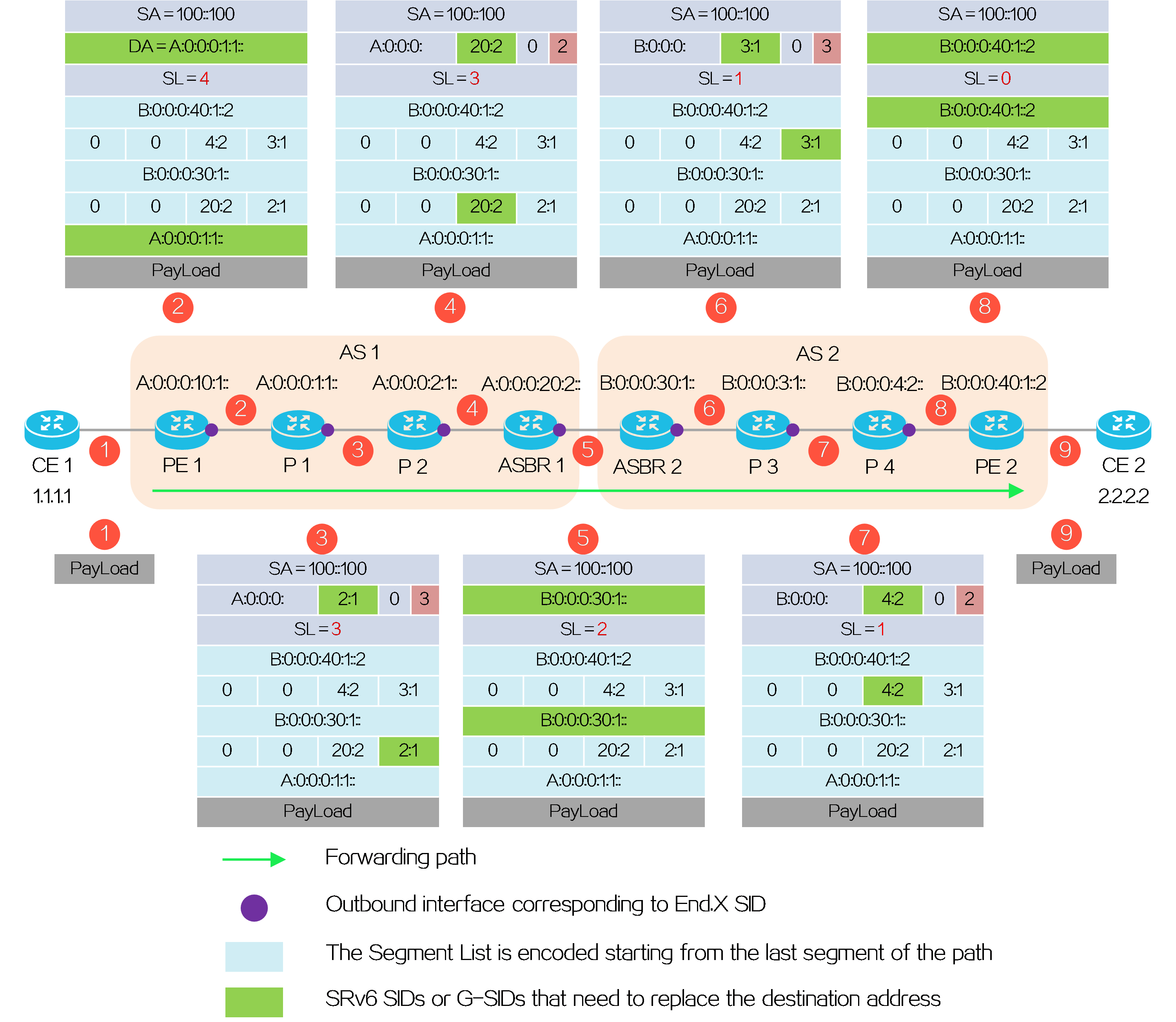
When CE 1 accesses CE 2, the SRv6 packet header processing and destination address replacement processes on the PE and P devices are as follows:
(1) CE 1 sends a packet for accessing CE 2 to PE 1.
(2) PE1 adds an SRH to the packet, and encapsulates the SID list <A:0:0:0:1:1::, A:0:0:0:2:1::, A:0:0:0:20:2::, B:0:0:0:30:1::, B:0:0:0:3:1::, B:0:0:0:4:2::>, and End.DT4 SID B:0:0:0:40:1::2. Then, it encapsulates the IPv6 basic header with the destination address A:0:0:0:1:1::. PE1 forwards the encapsulated packet to P1.
(3) Upon receiving the packet, P1 uses destination address A:0:0:0:1:1:: in the packet to look up the Local SID table for a match. If a matched End.X SID is found, P1 forwards the packet from the specified interface to P2 and updates the destination address. Because destination address A:0:0:0:1:1:: is a 128-bit SRv6 SID with the COC flag in the Segment List, the next SID is a G-SID. P1 decreases the SL by 1 (set to 3), and sets the SI to 3. Then, it locates the G-SID group based on [SL=3] in the packet, and then calculates the destination address based on the 32-bit G-SID corresponding to [SI=3]. The Common Prefix is A:0:0:0::/64, G-SID is 2:1, and SI is 3, which are combined to form a new destination address A:0:0:0:2:1::3.
(4) Upon receiving the packet, P2 uses destination address A:0:0:0:2:1:: (the two lowest SI values are ignored) in the packet to look up the Local SID table for a match. If a matched End.X SID is found, P2 forwards the packet from the specified interface to ASBR 1 and updates the destination address. Because destination address A:0:0:0:2:1:: is a 32-bit G-SID with the COC flag in the Segment List, the next SID is a G-SID. P2 decreases the SI by 1. Then, it locates the G-SID group based on [SL=3] in the packet, and then calculates the destination address based on the 32-bit G-SID corresponding to [SI=2]. The Common Prefix is A:0:0:0::/64, G-SID is 20:2, and SI is 2, which are combined to form a new destination address A:0:0:0:20:2::2.
(5) Upon receiving the packet, ASBR 1 uses destination address A:0:0:0:20:2:: (the two lowest SI values are ignored) in the packet to look up the Local SID table for a match. If a matched End.X SID is found, ASBR 1 forwards the packet from the specified interface to ASBR 2 and updates the destination address. Because destination address A:0:0:0:20:2:: is a 32-bit G-SID with the COC flag in the Segment List, ASBR 1 decreases the SL by 1 (set to 2), searches for the 128-bit SRv6 SID corresponding to [SL=2], replaces the destination address in the IPv6 header with this SRv6 SID. The new destination address is B:0:0:0:30:1::.
When the SI is decreased by 1, the G-SID identified by the SI is all zeros (End-of-Container, indicating the end of the 128-bit container). Therefore, ASBR 1 no longer replaces the destination address based on the SI. Instead, it decreases the SL by 1 and searches the next 128-bit container.
(6) Upon receiving the packet, ASBR 2 uses destination address B:0:0:0:30:1:: in the packet to look up the Local SID table for a match. If a matched End.X SID is found, ASBR 2 forwards the packet from the specified interface to P3 and updates the destination address. Because destination address B:0:0:0:30:1:: is a 128-bit SRv6 SID with the COC flag in the Segment List, the next SID is a G-SID. ASBR 2 decreases the SL by 1 (set to 1), and sets the SI to 3. Then, it locates the G-SID group based on [SL=1] in the packet, and then calculates the destination address based on the 32-bit G-SID corresponding to [SI=3]. The Common Prefix is B:0:0:0::/64, G-SID is 3:1, and SI is 3, which are combined to form a new destination address B:0:0:0:3:1::3.
(7) Upon receiving the packet, P3 uses destination address B:0:0:0:3:1:: (the two lowest SI values are ignored) in the packet to look up the Local SID table for a match. If a matched End.X SID is found, P3 forwards the packet from the specified interface to ASBR 1 and updates the destination address. Because destination address B:0:0:0:3:1:: is a 32-bit G-SID with the COC flag in the Segment List, the next SID is a G-SID. P3 decreases the SI by 1. Then, it locates the G-SID group based on [SL=1] in the packet, and then calculates the destination address based on the 32-bit G-SID corresponding to [SI=2]. The Common Prefix is B:0:0:0::/64, G-SID is 4:2, and SI is 2, which are combined to form a new destination address B:0:0:0:4:2::2.
(8) Upon receiving the packet, P4 uses destination address B:0:0:0:4:2:: (the two lowest SI values are ignored) in the packet to look up the Local SID table for a match. If a matched End.X SID is found, P4 forwards the packet from the specified interface to PE 2 and updates the destination address. Because destination address B:0:0:0:4:2:: is a 32-bit G-SID with the COC flag in the Segment List, ASBR 1 decreases the SL by 1 (set to 0), searches for the 128-bit SRv6 SID corresponding to [SL=0], and replaces the destination address in the IPv6 header with this SRv6 SID. The new destination address is B:0:0:0:40:1::2.
(9) Upon receiving the packet, PE 2 uses destination address B:0:0:0:40:1::2 to look up the Local SID table for a matched End.DT4 SID. If a matched End.DT4 SID is found, PE 2 removes the IPv6 header, matches VPN instance A based on the End.DT4 SID, searches for the routing table of VPN instance A, and sends the packet to CE 2.
4.11 Network slicing
Introduction
Network slicing divides a physical IP network into multiple logical networks, known as network slices, through various slicing techniques for specific services or users. As shown in the figure below, the physical network provides autonomous driving, remote healthcare, and wireless communication services. The services are allocated to independent network slices. Each network slice has its own logical topology, Service Level Agreement (SLA) requirements, and security and high availability requirements. Operators and enterprises do not need to build multiple dedicated networks. With the network slicing technology, they can maximize the utilization of existing network physical infrastructure resources and virtualize multiple logical networks for different services or users on demand. They can also flexibly provide differentiated network services on the logical networks.
Figure79 Network slicing application
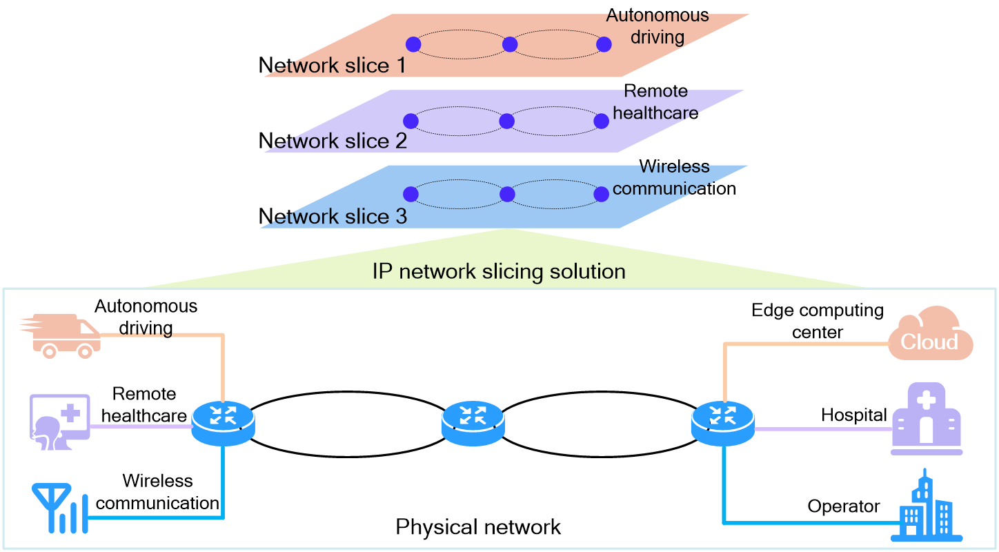
Benefits
Network slicing meets differentiated SLA requirements
For operators or large enterprises, one network carries a large number of services. The emerging new services constantly demand differentiated SLAs for this network. For example, the requirements of the autonomous driving service for latency and jitter are very strict but the demand for bandwidth is not high. However, the VR and high-definition video services have extremely high demand for network bandwidth but relatively low requirements for latency. In traditional networks, VPN technologies can only isolate private network routes on the control plane. Private networks still share physical link resources on the data forwarding plane. Differentiated SLAs cannot be achieved for different VPN services. In addition, building an independent dedicated network incurs high costs. The network slicing solution can provide different network slices for different services on demand at a lower cost. You can deploy different QoS policies and high availability protection technologies to network slices to meet differentiated SLA requirements.
Network slicing meets the requirements for network resource isolation
From the perspective of network resource security, some users or services require exclusive access to network resources, for example, government and financial dedicated lines. These users or services hope that the operator can provide secure and reliable isolation measures to avoid other users or services occupying network resources and leading to a degraded network experience. The network slicing solution can provide dedicated bandwidth resources for different users on the data forwarding plane and isolate routing information for different users and services on the control plane. In this way, network slicing meets the requirements for resource isolation.
Network slicing meets the requirements for flexibly and reliably customizing topology
When deploying network slicing in an SRv6 network, you can use the Flex-Algo technology to flexibly customize the logical network topology for tenants and use the TI-LFA FRR technology to provide millisecond-level failover. The FRR path switchover in one network slice does not affect the network slices of other tenants.
Network slicing meets the requirements for intelligent slice management
You can use an SDN controller to complete automatic deployment of network slices within minutes. In some networks, there are numerous tenants with diverse types of services and different bandwidth requirements. When deploying the network slicing solution, you can provide network slices for a large number of tenants or services and finely allocate bandwidth resources to the network slices to avoid waste.
Network slicing technology analysis
Network slicing is not specific to a certain network technology, but a comprehensive solution implemented through multiple network technologies. To meet the requirements of different users and services for differentiated SLAs, resource isolation, flexible topology customization, and intelligent slice management, you can simultaneously use slicing technologies such as subinterface slicing, FlexE technology, Flex-Algo flexible algorithm, and slice ID-based slicing to divide logical networks on a physical network. The subinterface slicing and FlexE technologies allocate bandwidth resources to network slices. The flexible algorithm and slice ID-based slicing technologies provide methods for dividing a physical network into logical network slices. This section provides comparison analysis for them.
Subinterface slicing (subinterface channelization)
This technology creates independent QoS scheduling queues on subinterfaces of high-speed physical interfaces, allocates bandwidths to the queues, and uses queue scheduling mechanisms to isolate different slice services during data forwarding. Slicing interfaces (subinterfaces with network slicing enabled) are forwarding interfaces for service data. They carry low-bandwidth and low-cost slicing services.
Figure80 Operating mechanism for the subinterface slicing technology
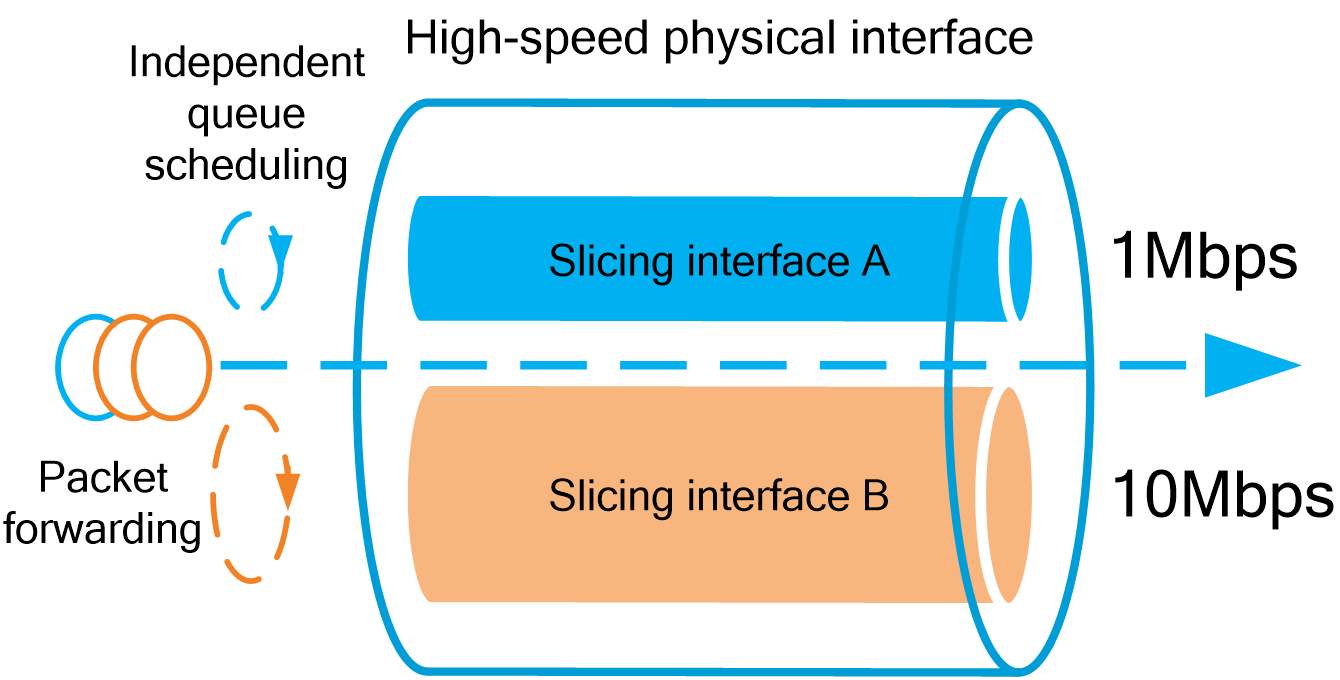
Characteristics:
· The bandwidth of each slicing interface is not less than 300 kbps.
· Both Ethernet interfaces and Layer 3 aggregate interfaces can be divided into slicing interfaces. Up to thousands of slices are supported.
· A slicing interface has independent scheduling queues and bandwidth resources.
· Hardware dependency is weak, and the queue scheduling mechanism introduces a small amount of latency.
FlexE technology (Flexible Ethernet)
This technology flexibly divides a bundled group of physical interfaces, which are multiplexed in time slots, into FlexE logical interfaces with different bandwidths. FlexE logical interfaces are used as data forwarding interfaces in the network slicing solution. Typically, they carry high-bandwidth and high-value-added industry slicing services.
Figure81 Operating mechanism for the FlexE technology
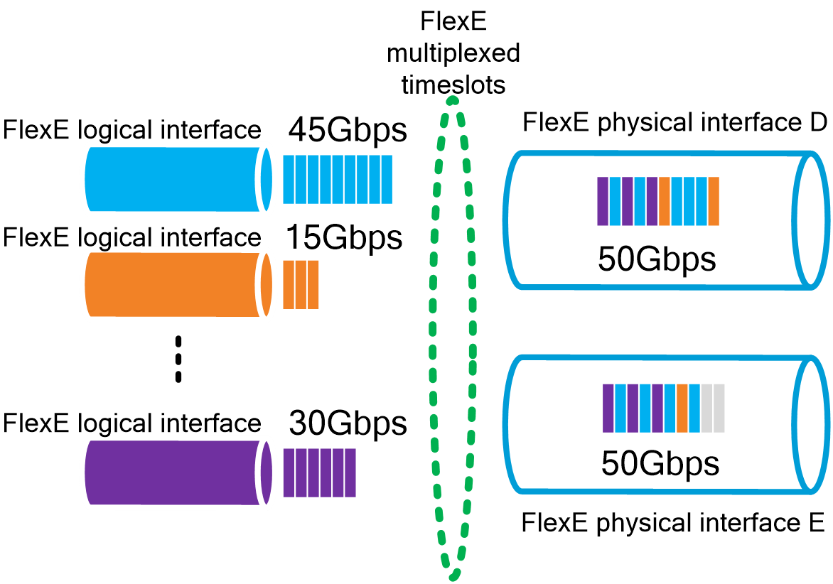
Characteristics:
· The bandwidth granularity of logical interfaces is 5 Gbps.
· Ultra-high bandwidth is available through port binding. Up to hundreds of slices are supported.
· A FlexE logical interface has independent MAC addresses and bandwidth resources.
· Hardware dependency is strong, with low latency and good stability.
Flex-Algo (Flexible Algorithm)
This technology uses IGP protocol messages to advertise topology constraint information used in route calculation, including the algorithm type, metric type, and link affinity attribute, to calculate paths that meet specific conditions based on the IGP protocol.
By using the link affinity attribute and other topology constraints, different Flex-Algo algorithms can be used on the control plane to divide a physical network into multiple independent logical networks as needed.
Figure82 Flex-Algo operating mechanism
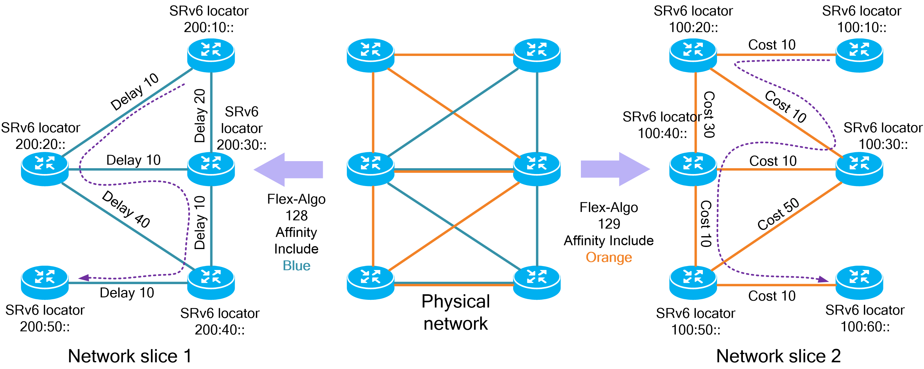
Characteristics:
· Flexible customization of topology—The biggest advantage of network slicing using the Flex-Algo technology is that you can design and plan the affinity attribute and other constraint conditions of links to flexibly customize the topology of network slices.
· Flexible routing mechanism—Users can flexibly calculate the optimal path in their respective slice network topologies by selecting appropriate metric types (for example, IGP link cost, link delay, or MPLS TE metric) as needed.
· High availability—Flex-Algo supports TI-LFA FRR backup path calculation. FRR backup path switchover in the slice network topology calculated by a Flex-Algo algorithm does not affect the slice network topologies calculated by other Flex-Algo algorithms.
· Control plane routing dependency—The routing results on the control plane affect the division of network slices. The maximum number of supported slices is limited. In an SRv6 network, the slice network topology calculated by each Flex-Algo algorithm requires a set of independent SRv6 locators, which leads to wastage of IPv6 address resources and increases the complexity of control plane routing.
Slice ID-based slicing
Network slicing based on slice IDs is a network slicing technology applied in SRv6 network scenarios. This technology identifies devices and data forwarding channels in a network slice through a globally unique slice ID, and it uses slice IDs to divide a network into network slices.
Service packets forwarded in a network slice carry slice ID information. When the device forwards the packets, it looks up the FIB table for the output interface and then forwards the packets through the data forwarding channels bound to the output interface based on the slice ID in the packets.
Figure83 Operating mechanism for slice ID-based slicing
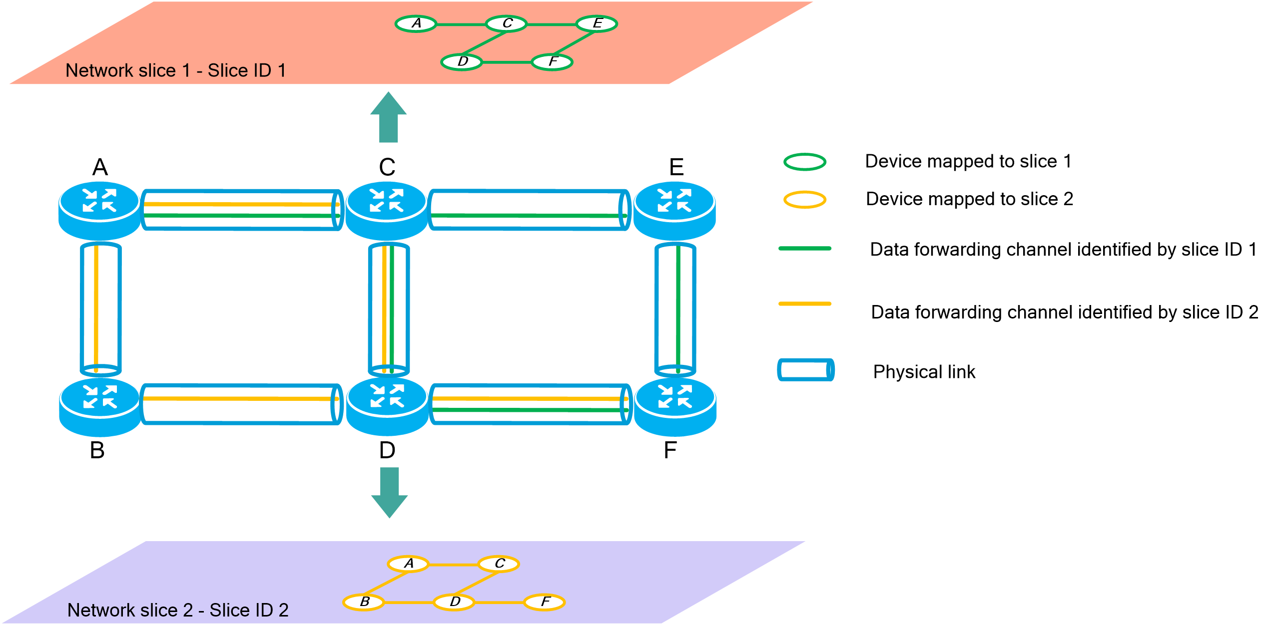
Characteristics:
· Support for massive slices—Network slicing based on slice IDs support a maximum of 6000 network slices. This technology can meet slicing requirements for massive services.
· Simplified configuration—To divide a network into network slices, you only need to configure slice IDs on devices and links.
· IPv6 address resource conservation—In an SRv6 network, the slice ID-based network slices share a set of SRv6 locators, which greatly saves IPv6 address resources compared to the Flex-Algo technology that calculates constraint paths based on the affinity attribute.
· Low control plane complexity—Compared to the Flex-Algo technology that calculates constraint paths based on the affinity attribute, the slice ID-based network slicing technology does not require calculating multiple topology networks on the control plane. The latter technology reduces control plane complexity. In data forwarding, the device uses the slice ID carried in packets to find data forwarding channels and achieve isolation of forwarding resources.
Network slicing comprehensive application
With the development of the concept of Industry 4.0, traditional factories are desired to upgrade to smart factories with the help of 5G technology from operators. More and more AI machines will be used in smart factories to replace human labor. Technical workers hope to control these AI machines remotely in the data control room. In addition, it is necessary to collect real-time alarm index information and video surveillance footages of various equipment and environments in the smart factories, and transmit the collected information and footages to the data control room for remote management.
In the operator bearer network as shown in the figure, the Flex-Algo technology is used to customize network topology for the smart factory to convert the network to an industrial sliced network. The slice ID-based network slicing technology is used to divide the industrial sliced network into three service network slices, which carry out remote control, video surveillance, and alarm monitoring services, respectively. Different quality guarantees are provided for different services based on their SLA requirements.
· Remote control service—The network slice with slice ID 1 carries out the remote control service. This network slice uses FlexE logical interfaces to forward data packets. The latency is stable and low. In addition, TI-LFA FRR is deployed to ensure high availability.
· Video surveillance service—The network slice with slice ID 2 carries out the video surveillance service. This network slice uses slicing interfaces operating at 1 Gbps to forward data packets. The bandwidth can meet the demands for hundreds of 1080P video surveillance services.
· Alarm monitoring service—The network slice with slice ID 3 carries out the alarm monitoring service. This network slice uses FlexE logical interfaces to forward data packets. The latency is stable and low.
Figure84 Network slicing comprehensive application
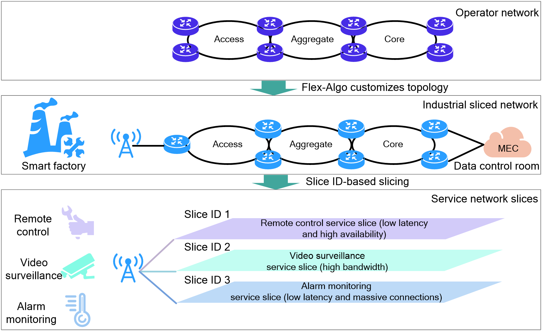
4.12 Subinterface channelization
Background
With the deployment and application of 5G networks, the types of services in IP transport networks are becoming increasingly diverse. Different types of services have significantly different requirements for network performance. For example, enhanced mobile broadband (eMBB), massive machine type communications (mMTC), and ultra-reliable and low-latency communications (uRLLC) have high requirements for bandwidth, connection count, and latency, respectively. Therefore, network administrators want to perform slice-based transport and independent scheduling for different types of services.
Network slicing divides a physical network into multiple virtual networks based on different service requirements. Network slicing not only reduces network construction costs but also meets the requirements of flexible, diverse service application scenarios. Subinterface channelization (also called subinterface slicing) a network slicing technique. Subinterface channelization divides a high-rate interface into multiple low-bandwidth subinterfaces for different services, isolating different types of services.
Figure85 Subinterface channelization applications
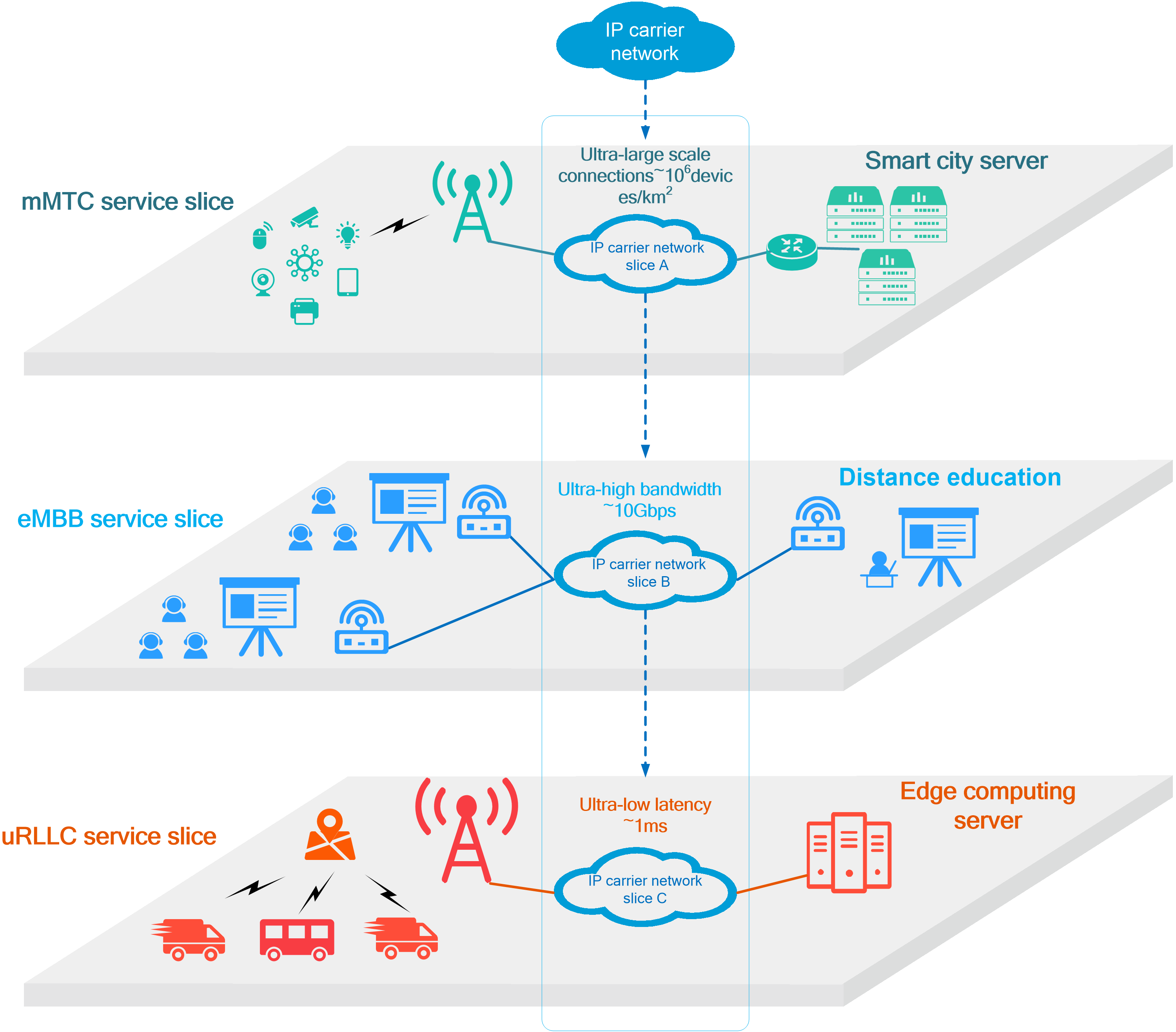
Operating mechanism
Subinterface channelization is a fine-grained network slicing technique. You can implement subinterface channelization by creating subinterfaces on a high-speed interface and configuring bandwidth for some subinterfaces. These subinterfaces configured with bandwidth are called channelized subinterfaces or sliced subinterfaces. A channelized subinterface exclusively uses the allocated bandwidth and is scheduled with a dedicated queue.
As shown in the following figure, packets of channelized subinterfaces A and B, common subinterface C, and main interface exist in the outgoing direction of the interface.
· The device assigns channelized subinterfaces A and B traffic management queues independent of the main interface for independent QoS scheduling. A channelized subinterface has exclusive bandwidth. The main interface and other subinterfaces cannot occupy the bandwidth of the channelized subinterface. Each channelized subinterface can be considered as an independent interface.
· The packets of common subinterfaces and main interface enter the main interface queues for scheduling. They share the remaining bandwidth of the interface (total bandwidth of the main interface minus total bandwidth of all channelized subinterfaces).
Figure86 Operating mechanism of subinterface channelization
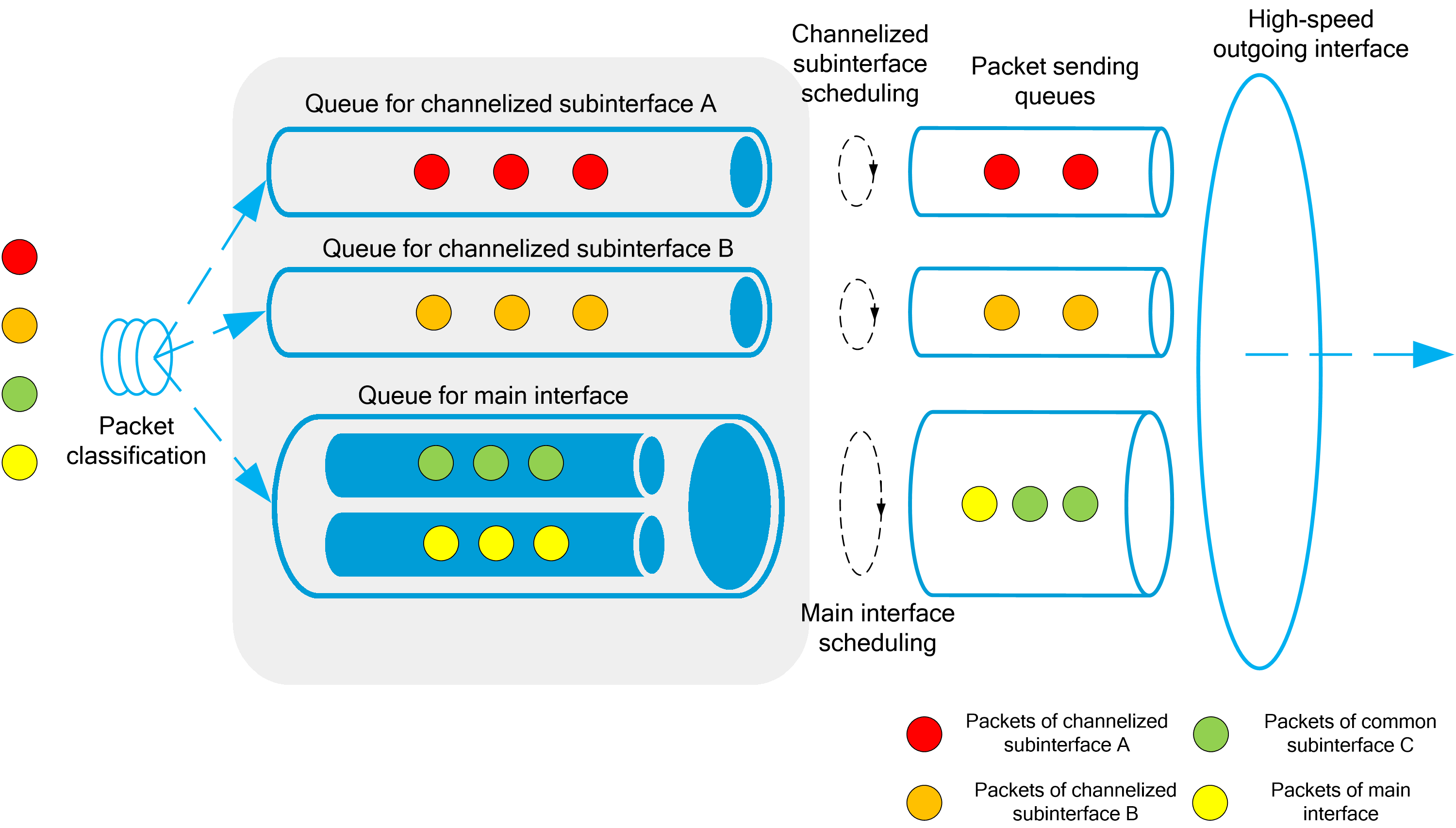
|
|
Benefits
Common network slicing technologies include subinterface channelization and FlexE. The following table compares subinterface channelization with FlexE. Subinterface channelization has advantages such as simple configuration, zero dependency on hardware and standards, and applicability to fine-grained slicing scenarios with bandwidth smaller than 1Gbps.
Table15 Subinterface channelization technology features
|
Benefits |
Subinterface channelization |
FlexE |
|
Configuration complexity |
Simple |
Medium |
|
Minimum bandwidth granularity |
300 kbps |
5 Gbps: Commercialized 1 Gbps: Not standardized |
|
Number of slices supported |
Thousands |
Hundreds |
|
Hardware dependency |
Low |
High |
|
|
Application scenarios
Subinterface channelization is applicable to the following scenarios:
· Isolating different service flows between the edge network and the backbone aggregation network.
· Isolating different service flows between the customer-side CE and the ISP-side edge device PE.
In a typical VPN as shown in the following figure, services including voice, mail, and remote live broadcasting exist between two sites of the user VPN. According to the requirements of the services for latency and bandwidth, the network administrator configures channelized subinterfaces for different services on PEs and CEs. These channelized subinterfaces ensure that the service flows between the ISP backbone network and the customer network are isolated from each other.
Figure87 Subinterface channelization application scenarios
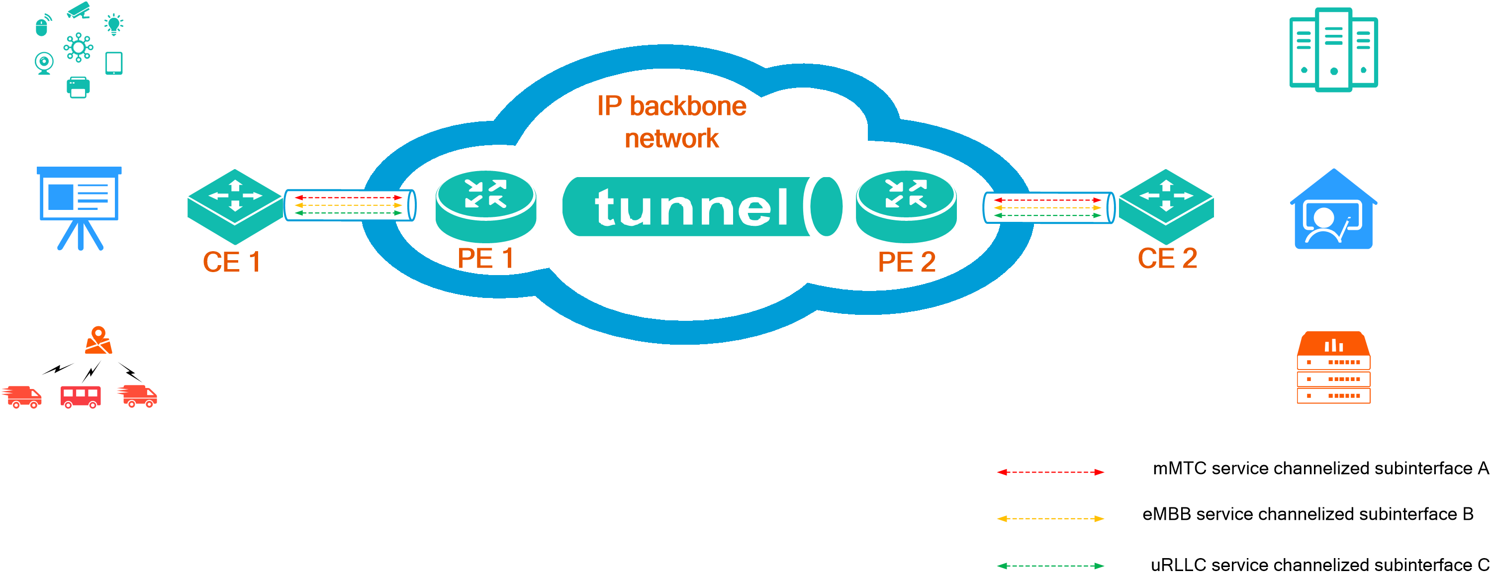
4.13 FlexE
About FlexE
Flexible Ethernet (FlexE) is a low-cost and dynamically configurable carrier-grade interface technology. Based on Ethernet technology, FlexE uses timeslot interleaving and bonding (link aggregation) techniques to provide high-speed transmission and flexible bandwidth allocation.
Figure88 FlexE benefits

FlexE implementation
The key roles in FlexE include:
· FlexE physical interface
Physical Ethernet interface switched to FlexE mode.
· FlexE group
A set of FlexE physical interfaces. The bandwidth of a FlexE group is the sum of the bandwidth of each FlexE physical interface in the group.
· FlexE logical interface
Logical interface automatically generated by the device when the FlexE physical interface is created. Such an interface allows for flexible bandwidth allocation for traffic forwarding. The bandwidth allocated to the FlexE logical interface cannot exceed the sum of the bandwidth of each FlexE physical interface in the FlexE group.
|
|
FlexE bonds multiple FlexE physical interfaces into a FlexE group, and flexibly allocates the total bandwidth to each FlexE logical interface according to traffic requirements. In this way, FlexE allocates different bandwidths to different services and different leased line subscribers.
FlexE divides the physical layer of a FlexE physical interface into several identical timeslots with the same bandwidth. As shown in the following figure, the timeslot bandwidth is 5G. The bandwidths of timeslots can be flexibly combined and allocated to FlexE logical interfaces.
Figure89 FlexE logical interface bonding and time slot allocation
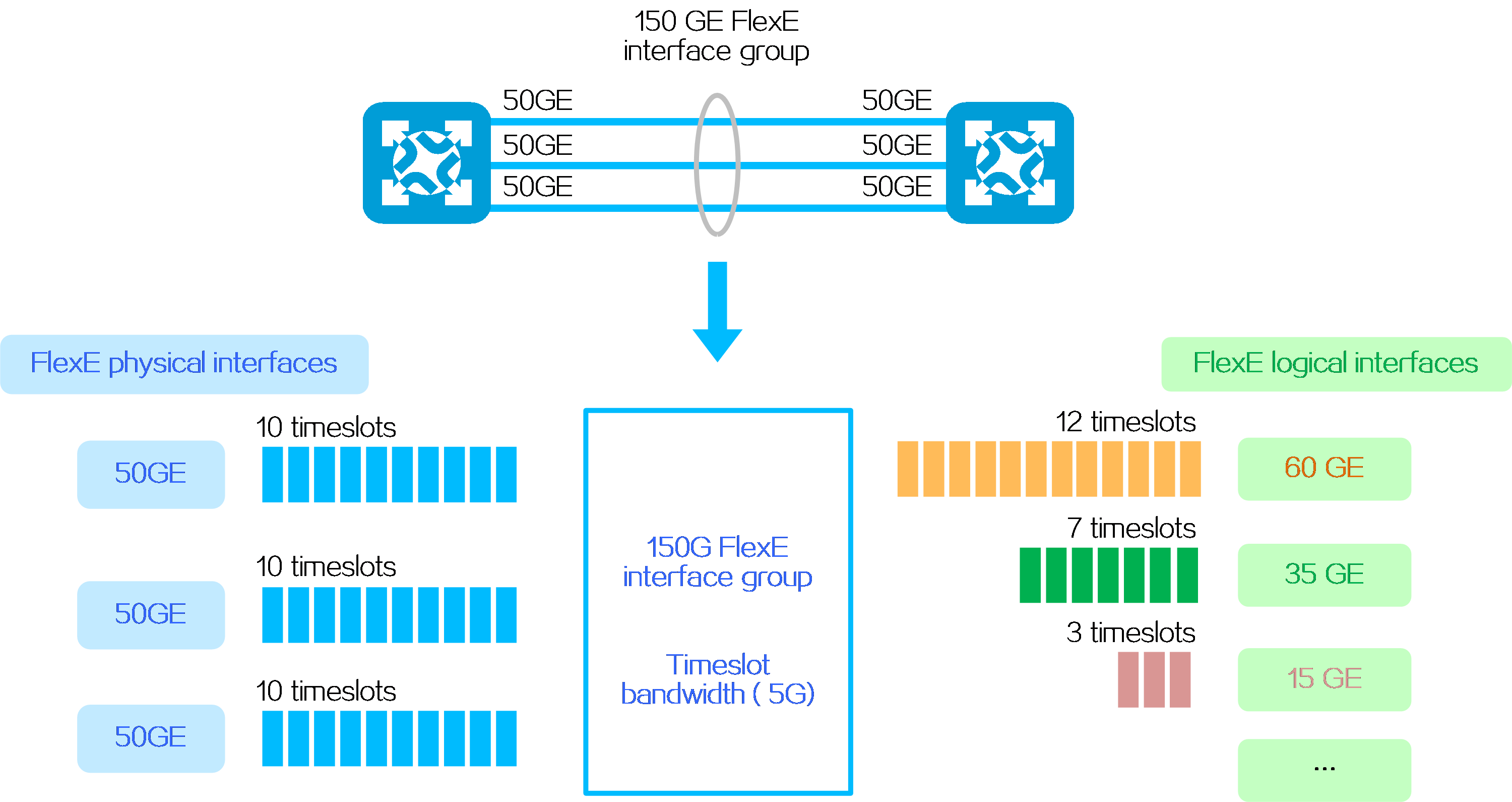
Technical benefits
Flexible bandwidth expansion
FlexE decouples service bandwidth requirements from physical interface bandwidth, and uses bonding (link aggregation) and timeslot interleaving to easily expand bandwidth through low-speed interfaces. FlexE realizes gradual service bandwidth upgrade (10G->50G->100G->200G->400G->xT).
Figure90 FlexE bandwidth expansion
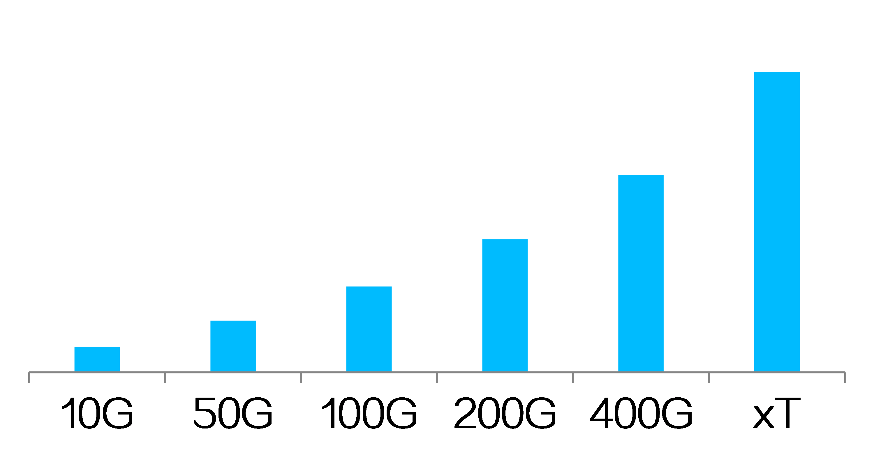
100% balanced bandwidth assignment
FlexE enables the traffic to be strictly evenly distributed among logical interfaces of a FlexE group through a timeslot control mechanism. FlexE can adjust the bandwidth of FlexE logical interfaces in real time by increasing or decreasing the number of timeslots to adapt to service traffic changes.
Figure91 Balanced bandwidth assignment

Service isolation
Each FlexE logical interface has an independent MAC address, and thus the resources forwarded between different interfaces are isolated. FlexE transmits different services on different FlexE logical interfaces to isolate services.
Figure92 FlexE service isolation
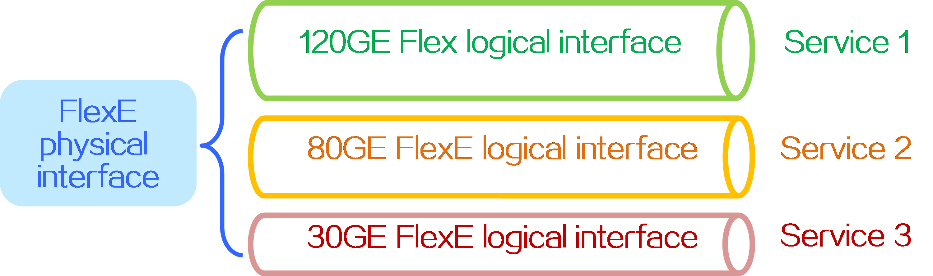
Simple service deployment
When you deploy new services in ISP networks, you can deploy them on newly added FlexE logical interfaces without adjusting the deployment of physical interfaces. This makes the deployment of new services simpler and faster.
Figure93 Simple FlexE service deployment
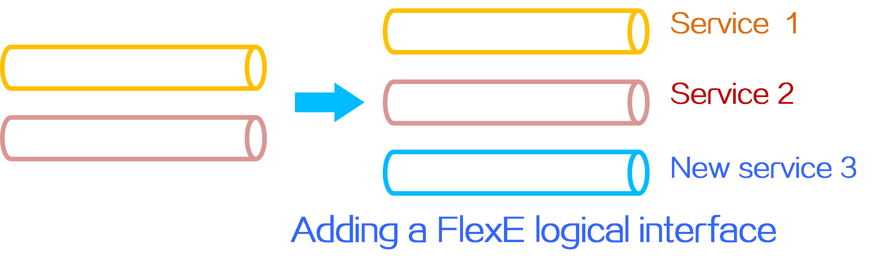
Application scenarios
Ultra-high-bandwidth interface
The Ethernet standard defined by IEEE 802.3 provides fixed rates (such as 10GE and 100GE), which cannot meet the requirements of flexible bandwidth networking. FlexE allows for flexible combination of interface bandwidth through bonding (link aggregation), making links with higher bandwidth possible (such as 5*100GE and 10*100GE).
Figure94 FlexE interface bandwidth expansion
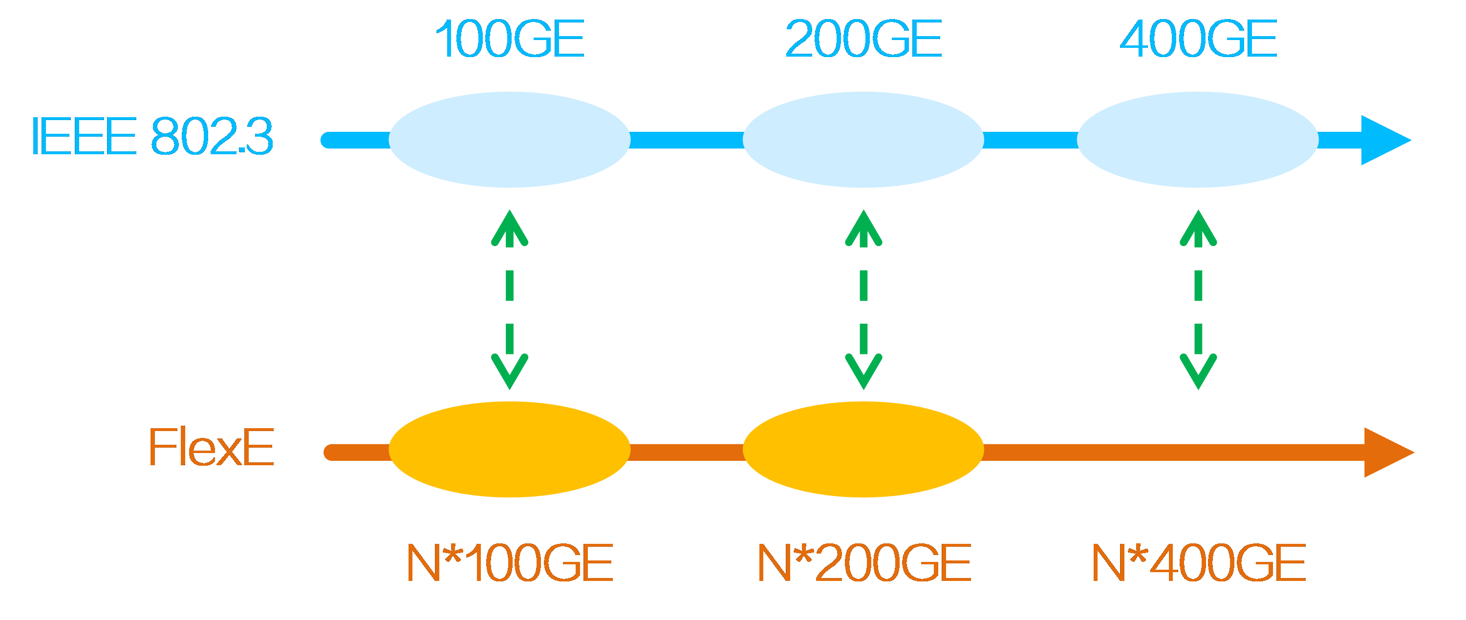
Leased line access
The emergence of more new network services drives the increasing diversity of leased line services. For example, some services require exclusive bandwidth and extremely low latency, while others concern more about privacy protection and high security. The leased line services based on FlexE logical interfaces can well meet the multi-service requirements.
Figure95 FlexE supports multiple leased line services
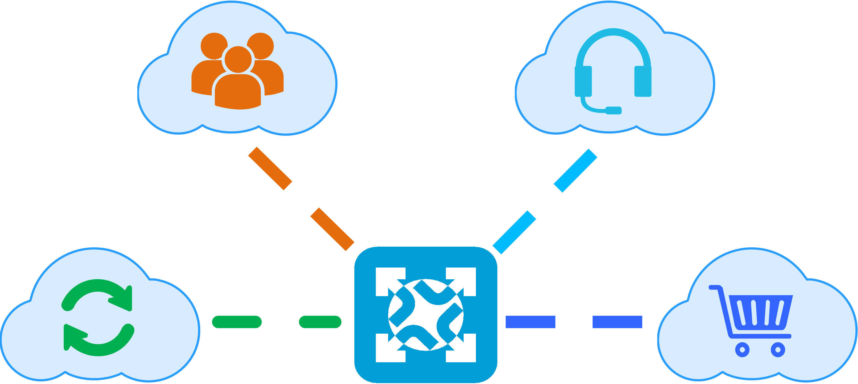
5G network slicing
Network slicing divides network resources into slices to meet the transport requirements of different services and ensure the SLAs (such as bandwidth and latency) for services. FlexE is applied to 5G networks. By using the service traffic isolation feature of FlexE logical interfaces, network slicing enables a 5G network to transport different 5G services (such as eMBB and URLLC) in the same IP network, and provides different SLAs for different services.
Figure96 5G network slicing
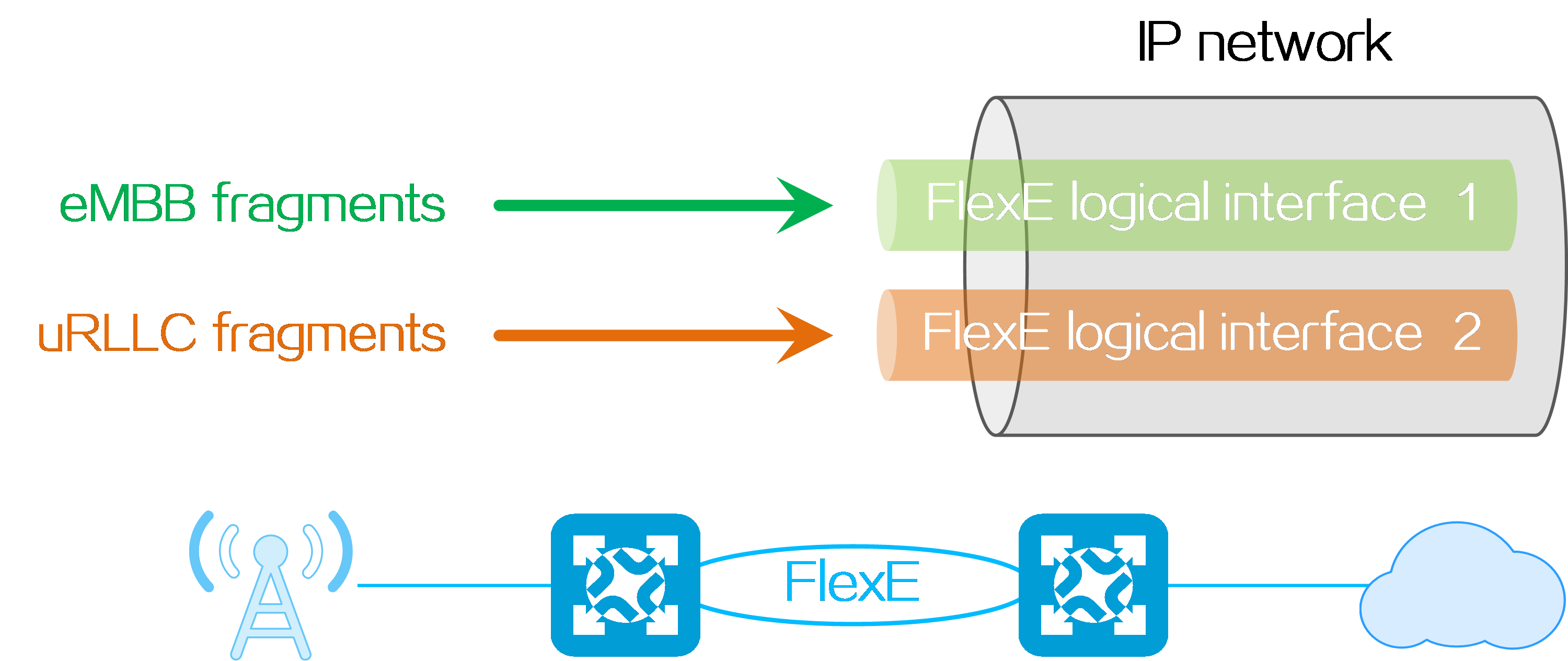
4.14 Flex-Algo
About Flex-Algo
Traditionally, the interior gateway protocol (IGP) calculates the optimal path to a destination based on the link cost. When the link cost is no longer the only path quality metric, the traditional IGP route calculation algorithm cannot meet different requirements of users. For example, streaming media and video conferencing require low latency, and require IGP to calculate the optimal path according to the link latency. Additionally, IGP must exclude the links with failure risks during calculation.
Flexible Algorithm (Flex-Algo) effectively meets these requirements. With Flex-Algo, you can choose the optimal path calculation method and metric type as needed. You can plan different network topologies for different services for flexible control of path selection and traffic engineering.
Operating mechanism
Algorithm definition and advertisement
A Flex-Algo definition (FAD) is uniquely identified by an ID in the range of 128 to 255. An FAD contains three configurable attributes, including route calculation type, metric type, and topology constraints.
Figure97 FAD and advertisement
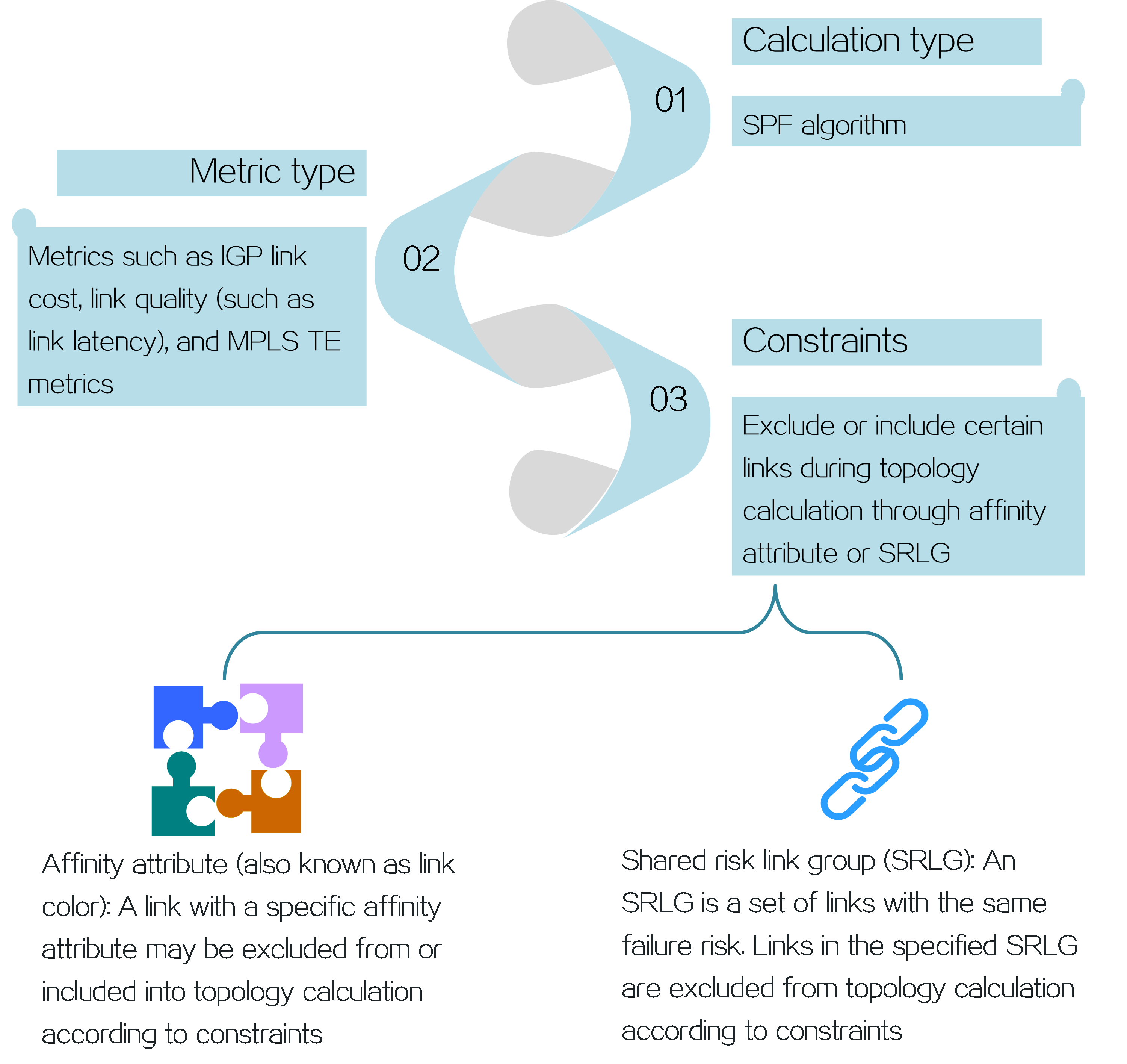
Generating the topology
Selecting an FAD
In an IGP domain, different devices can define FADs with the same algorithm ID, and those FADs can be different. For the calculation results to be consistent on these devices, only one of these FADs with the same algorithm ID can be applied. A device selects an FAD as follows:
· The FAD with the highest priority will be selected from the FADs advertised within the IGP domain.
· The FAD with the greatest system ID will be selected from the FADs that have the highest priority.
For example, as shown in the following figure, both Device A and Device B have defined the FADs with ID 130, but the two FADs are different. After the FADs are advertised with IGP, the FAD advertised by Device A is selected. Then, both Device A and Device B use the link cost as the metric for path calculation when using FAD 130.
Figure98 Selecting an FAD
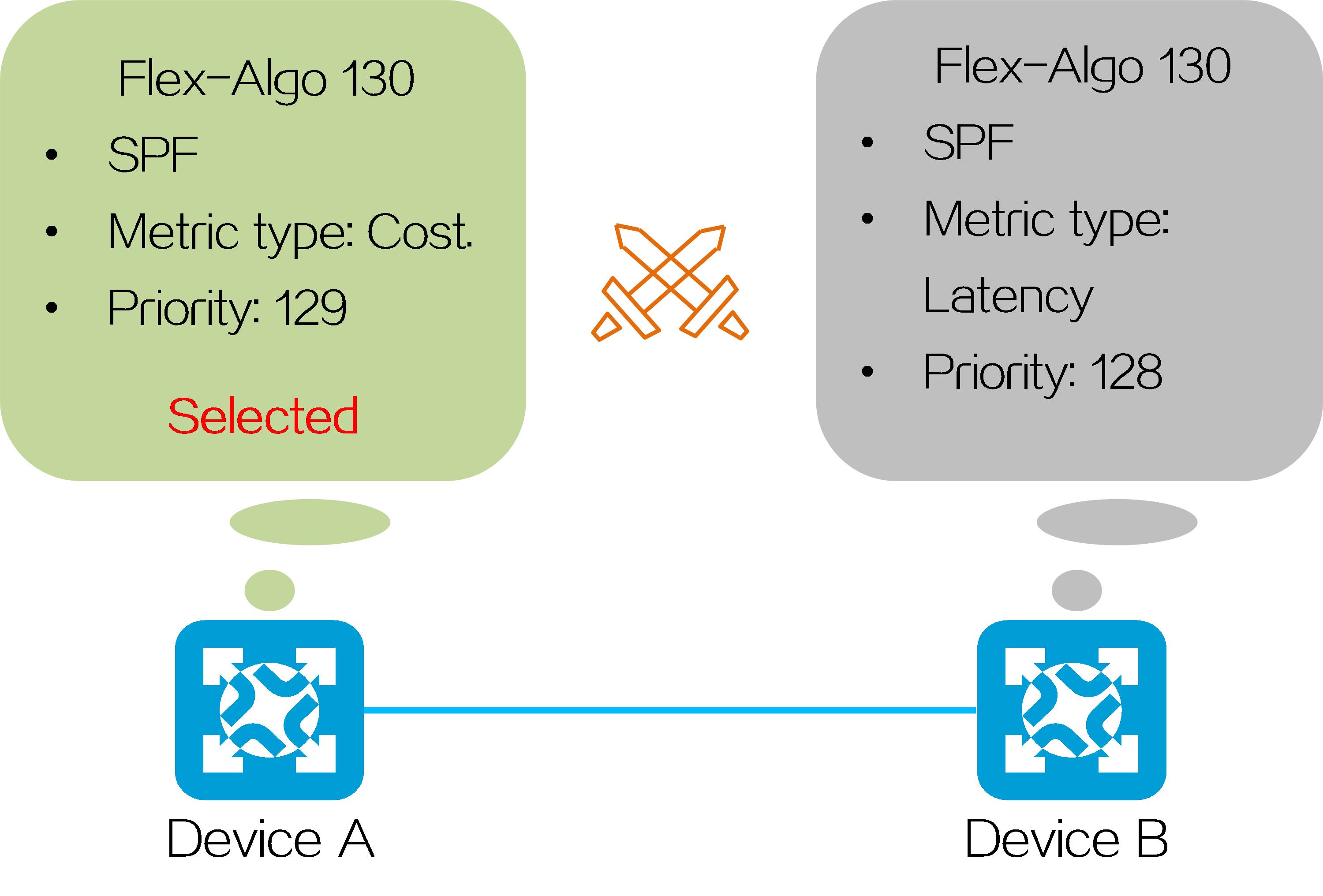
Calculating the topology
After all devices select an FAD, Flex-Algo will identify whether the affinity attributes and SRLGs of links match the constraints. The matching links will be included into or excluded from the topology by Flex-Algo. Flex-Algo supports the following constraints:
Figure99 Rules with different constraints

For example, if the FAD is defined with an Exclude-Any rule for red links, the topology generated will exclude links with the affinity attribute red.
Figure100 Generating topology with Exclude-Any rules matching affinity attributes
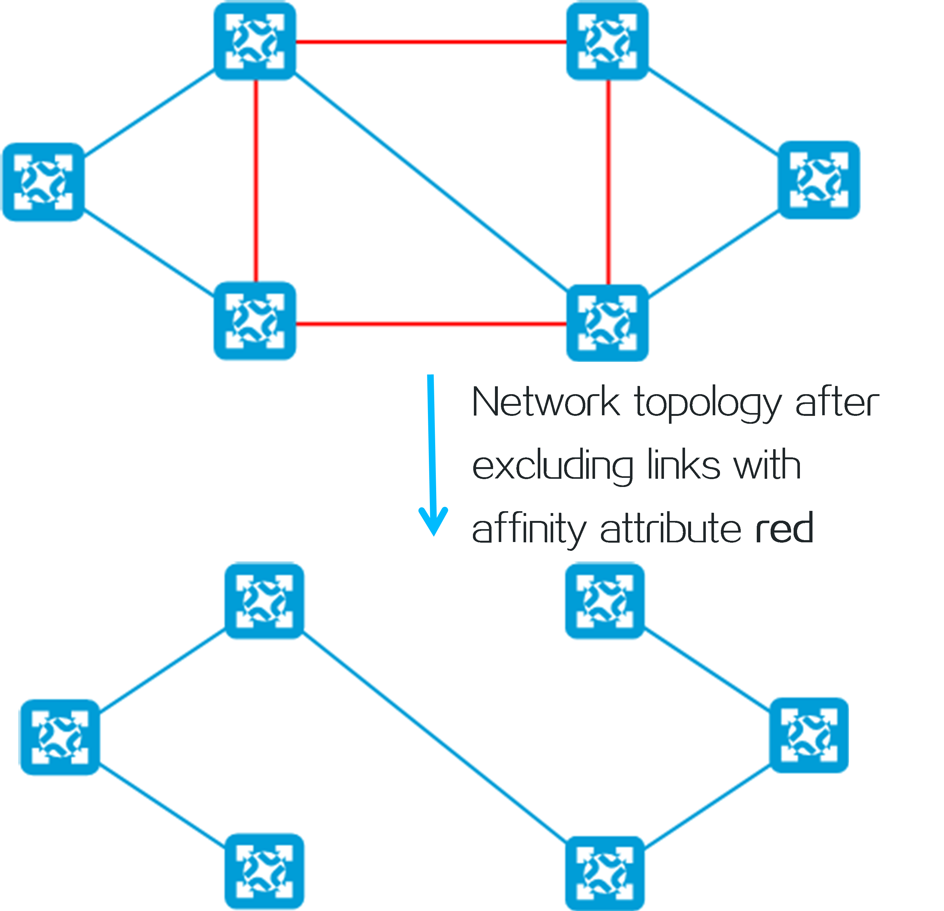
Calculating the optimal path based on the planned topology
In the generated topology, Flex-Algo calculates the optimal path according to the calculation type and metric type advertised by an FAD. Different types of metrics will result in completely different optimal paths. For example, as shown in the following figure, the calculated optimal path from Device A to Device B is the green one when the metric type is cost. The calculated optimal path from Device A to Device B is the purple one when the metric type is latency (delay).
Figure101 Calculating the optimal path by using different types of metrics
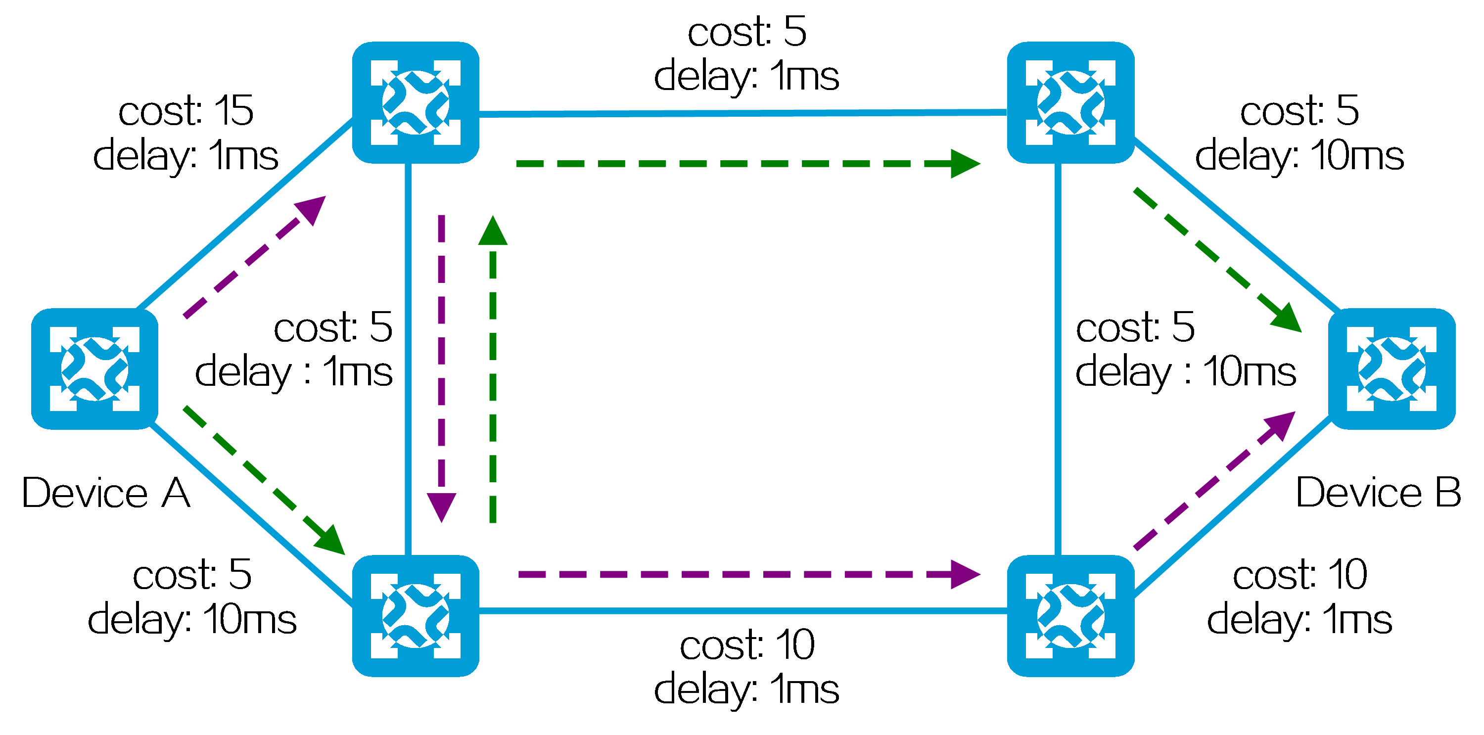
Technical benefits
High flexibility
You can freely choose the metric type and constraints for Flex-Algo according to the requirements of different services.
Network slicing
Network slicing divides a physical network into multiple virtual networks based on different service requirements. Flex-Algo can implement network slicing to transport different services in different network slices by topology planning based on constraints. As shown in the following figure, the green path has low latency but high cost, while the red path has high latency but lower cost. After network slicing through Flex-Algo, important traffic from Device A to Device B can be forwarded only over the green path and common traffic only over the red path. In this way, network slicing isolates common traffic and important traffic, and saves the cost while ensuring the service quality.
Figure102 Planning the topology based on Flex-Algo
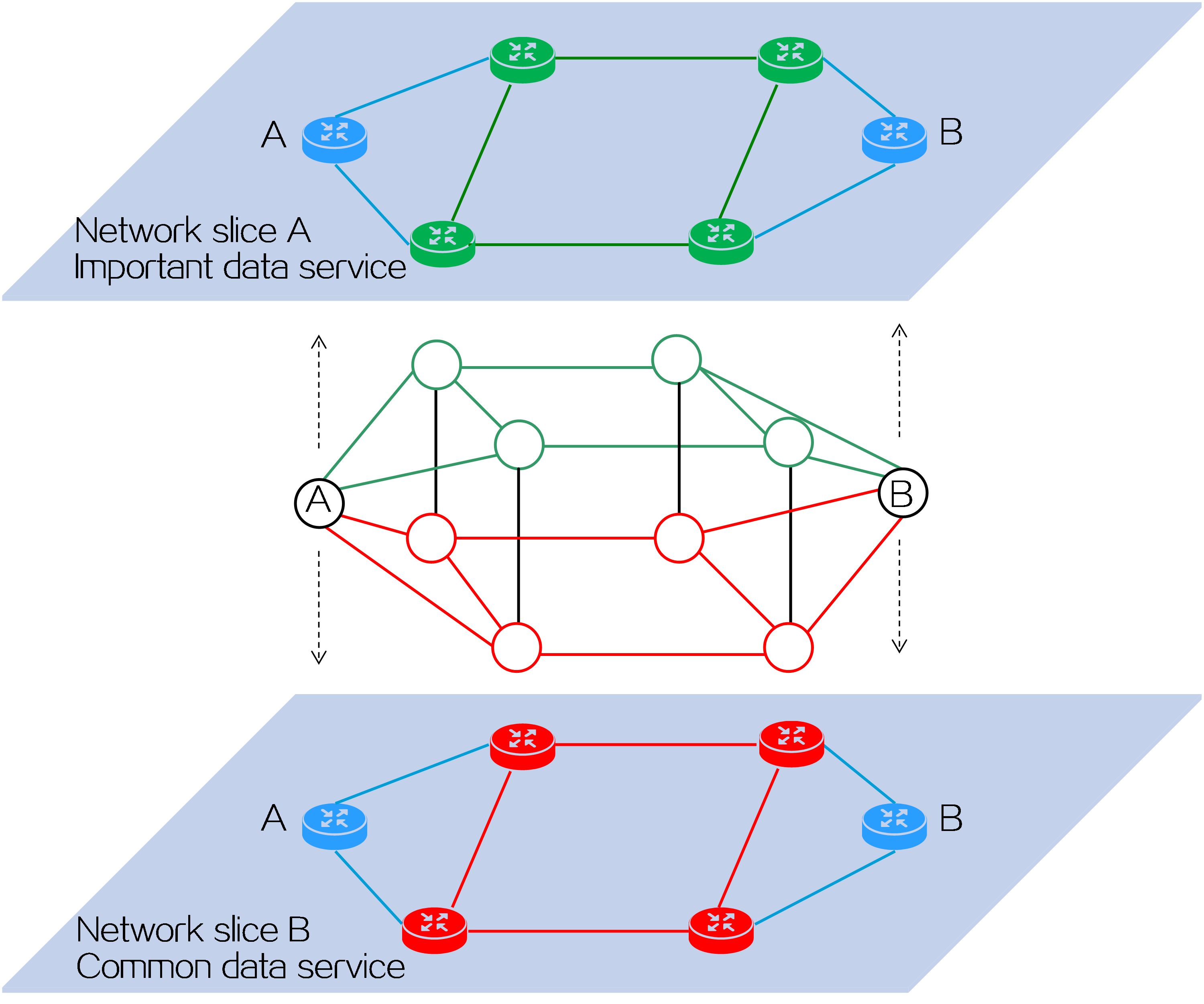
Loop avoidance mechanism
All the Flex-Algo-capable devices in an IGP domain use the same FAD. Therefore, the calculation results are the same on all devices, theoretically avoiding a loop.
High reliability
Flex-Algo supports calculating an alternate path through Topology-Independent Loop-Free Alternate Fast Reroute (TI-LFA FRR). When a link or node on the network fails, the traffic will be quickly switched to the alternate path for continuous forwarding, thus minimizing data loss.
Figure103 TI-LFA FRR application
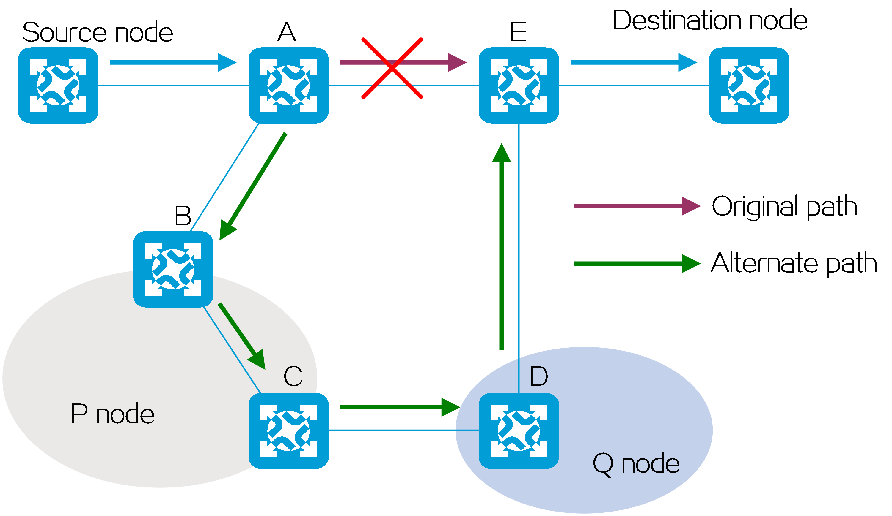
Wide applications
Flex-Algo is applicable to SRv6 and SR-MPLS networks to calculate the public network forwarding paths for SRv6 SIDs or SR-MPLS nodes. Also, Flex-Algo directly calculates the SID lists for SRv6 TE policies and SR-MPLS TE policies, and thus meets the requirements of traffic engineering.
Application scenarios
Calculating the optimal path to a locator prefix on an SRv6 network
After an SRv6 locator prefix is associated with Flex-Algo, IGP will advertise it. After receiving the IGP route with the SRv6 locator prefix, other nodes will use Flex-Algo to calculate the optimal path to the node where the SRv6 locator prefix resides.
· When Flex-Algo is not used, the PE will calculate the optimal path to the node where locator prefix A5:80::/64 resides based on the IS-IS link cost, as shown in the following figure.
Figure104 Calculating the optimal path to the locator prefix (without using Flex-Algo)
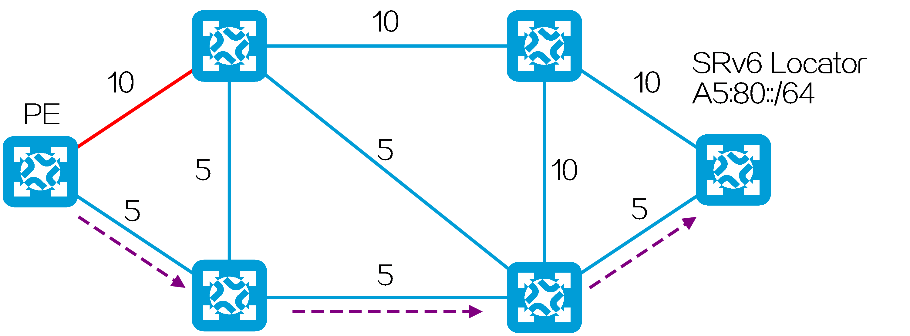
· Locator prefix A5:80::/64 is associated with the following FAD:
¡ Calculation type—SPF algorithm.
¡ Metric type—IS-IS link cost.
¡ Constraint—Includes affinity attribute red.
The PE calculates the optimal path to the node where locator prefix A5:80::/64 resides based on Flex-Algo, as shown in the following figure.
Figure105 Calculating the optimal path to the Locator prefix (based on Flex-Algo)
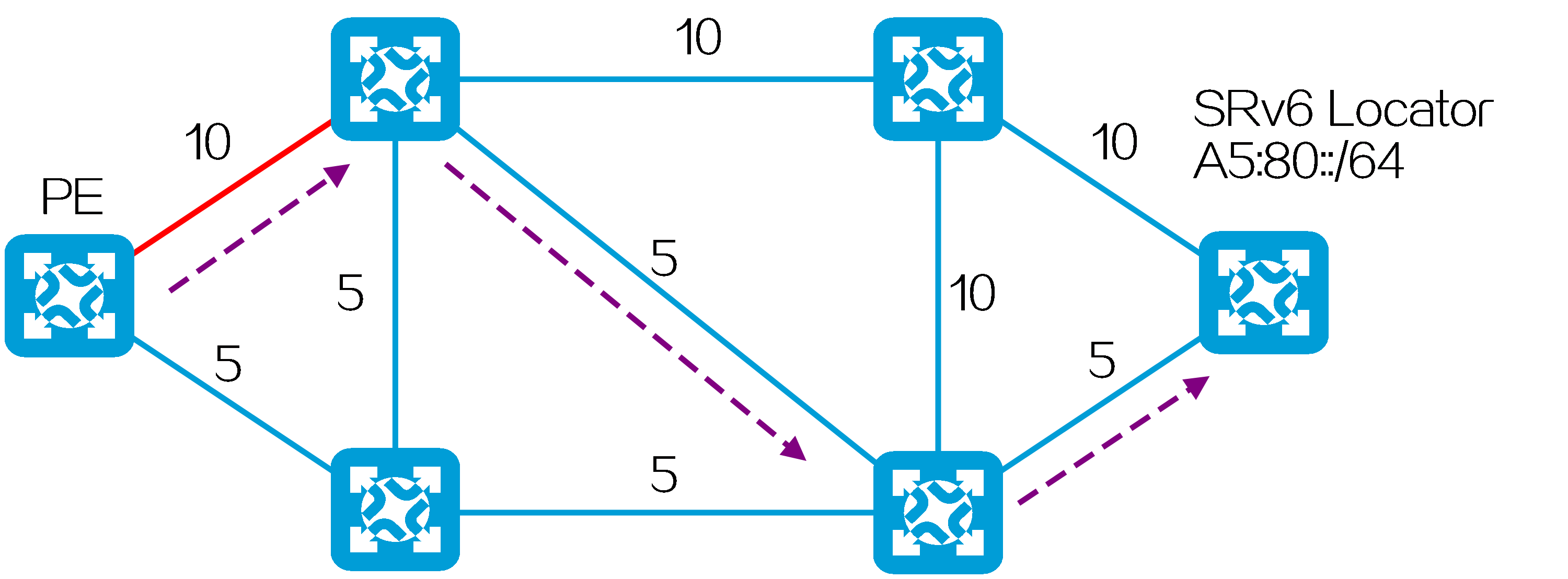
Calculating the shortest path to each SR node
SR nodes collect prefix SIDs on the SR-MPLS network and the IGP network topology through IGP. Then, an SR node calculates the optimal path to any other SR node by using Flex-Algo, and establishes an SRLSP on this path.
(1) Device F assigns to its loopback interface address a SID with an index value of 21. All nodes on the network use IGP to advertise the prefix SID (SRGB base value + index value).
Figure106 Advertising prefix SID information
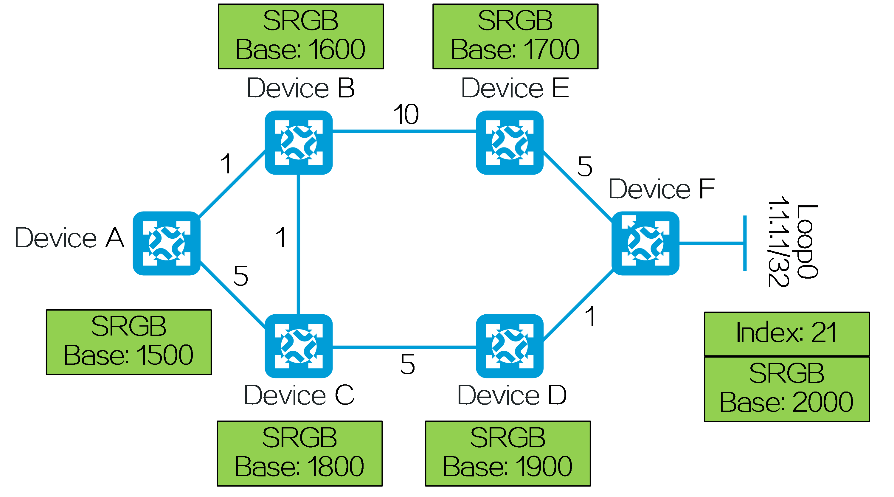
(2) Device F associates its prefix SID with the following FAD:
· Calculation type—SPF algorithm.
· Metric type—IS-IS link cost.
· Constraint—Exclude affinity attribute red.
The FAD is advertised to all nodes on the network.
Figure107 Calculating the optimal path to an SR-MPLS node by using Flex-Algo
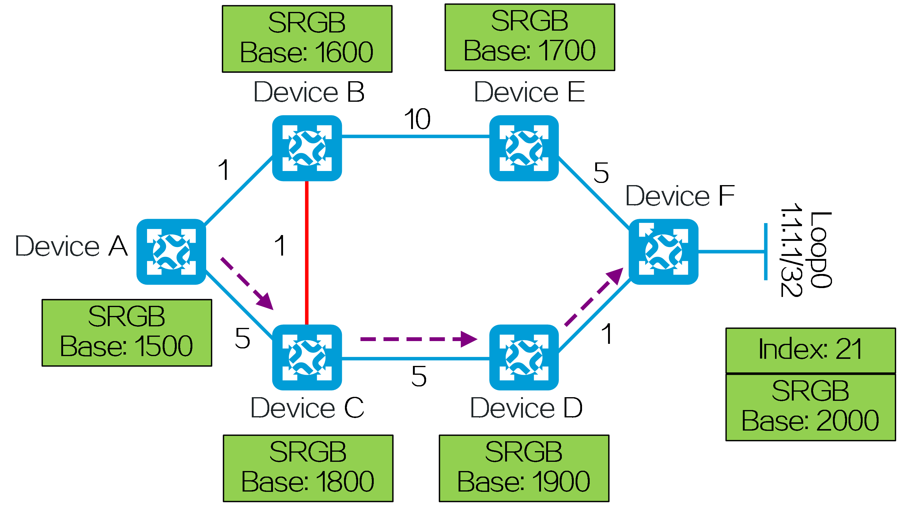
(3) As shown in the preceding figure, Device A uses Flex-Algo to calculate the path to Device F as Device A-> Device C-> Device D-> Device F, and establishes an SRLSP on this path. The label forwarding entries established by each SR node on the path are as shown in the following figure.
Figure108 Label forwarding entries established by each SR node
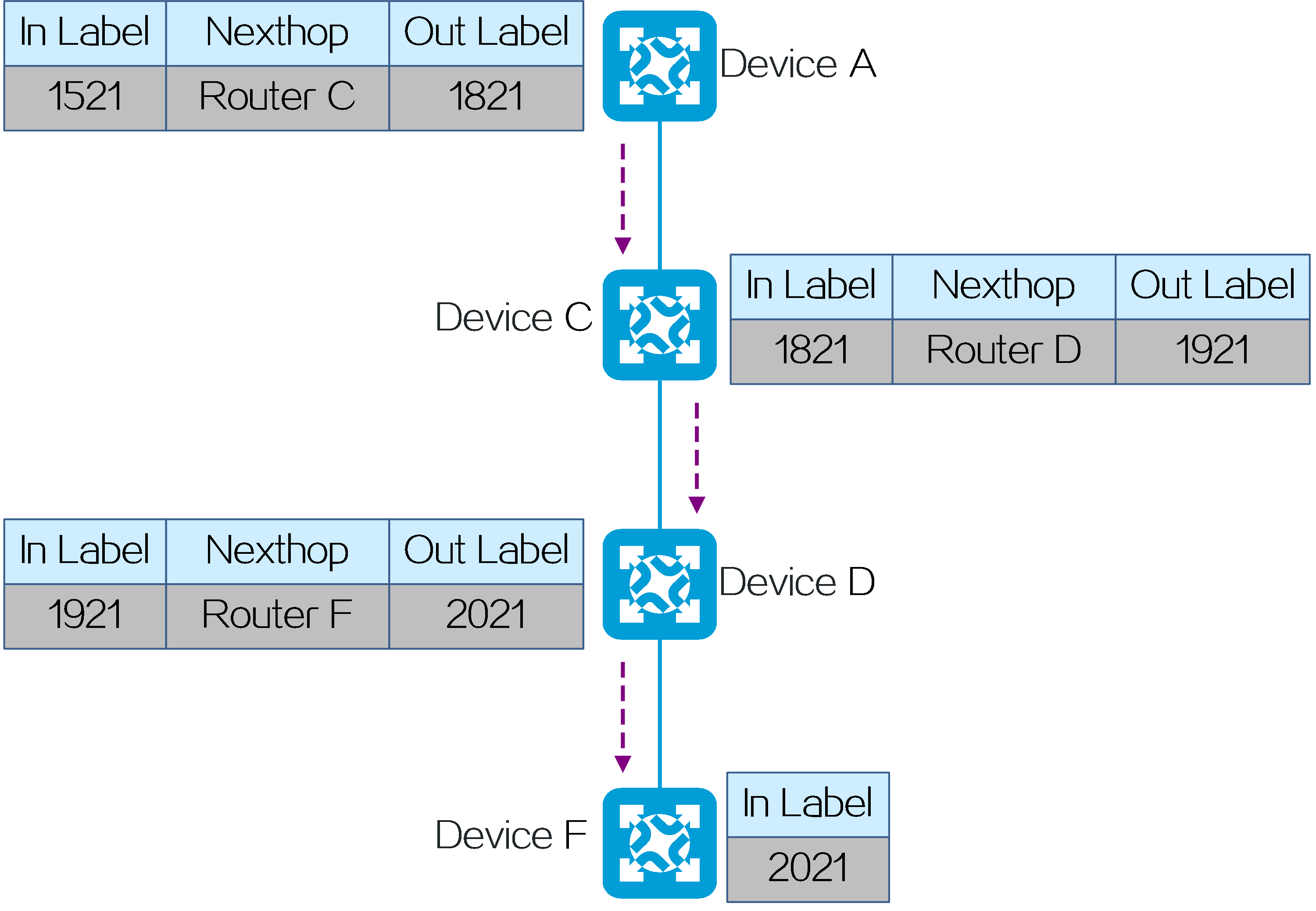
Calculating the SID list for an SRv6 TE policy/SR-MPLS TE policy
The SRv6 TE policies and SR-MPLS TE policies can be created automatically through the On-Demand Next-Hop (ODN) feature. If the Color attribute in a BGP route received by a device matches an ODN template, an SRv6 TE policy or SR-MPLS TE policy will be automatically created according to the ODN template.
After the ODN template is associated with Flex-Algo, Flex-Algo automatically calculates the SID list for the candidate paths of the SRv6 TE policy or SR-MPLS TE policy created by ODN. On SRv6 and SR-MPLS networks, the process of dynamically calculating the SID list by Flex-Algo is similar. An SRv6 network is taken as an example here.
(1) On Device A, an ODN template with the Color attribute value of 60 is created and associated with the following FAD:
· Calculation type—SPF algorithm.
· Metric type—IS-IS link cost.
· Constraint—Exclude affinity attribute red.
Figure109 Calculating the SID list by using Flex-Algo for the candidate paths of an SRv6 TE policy created by ODN
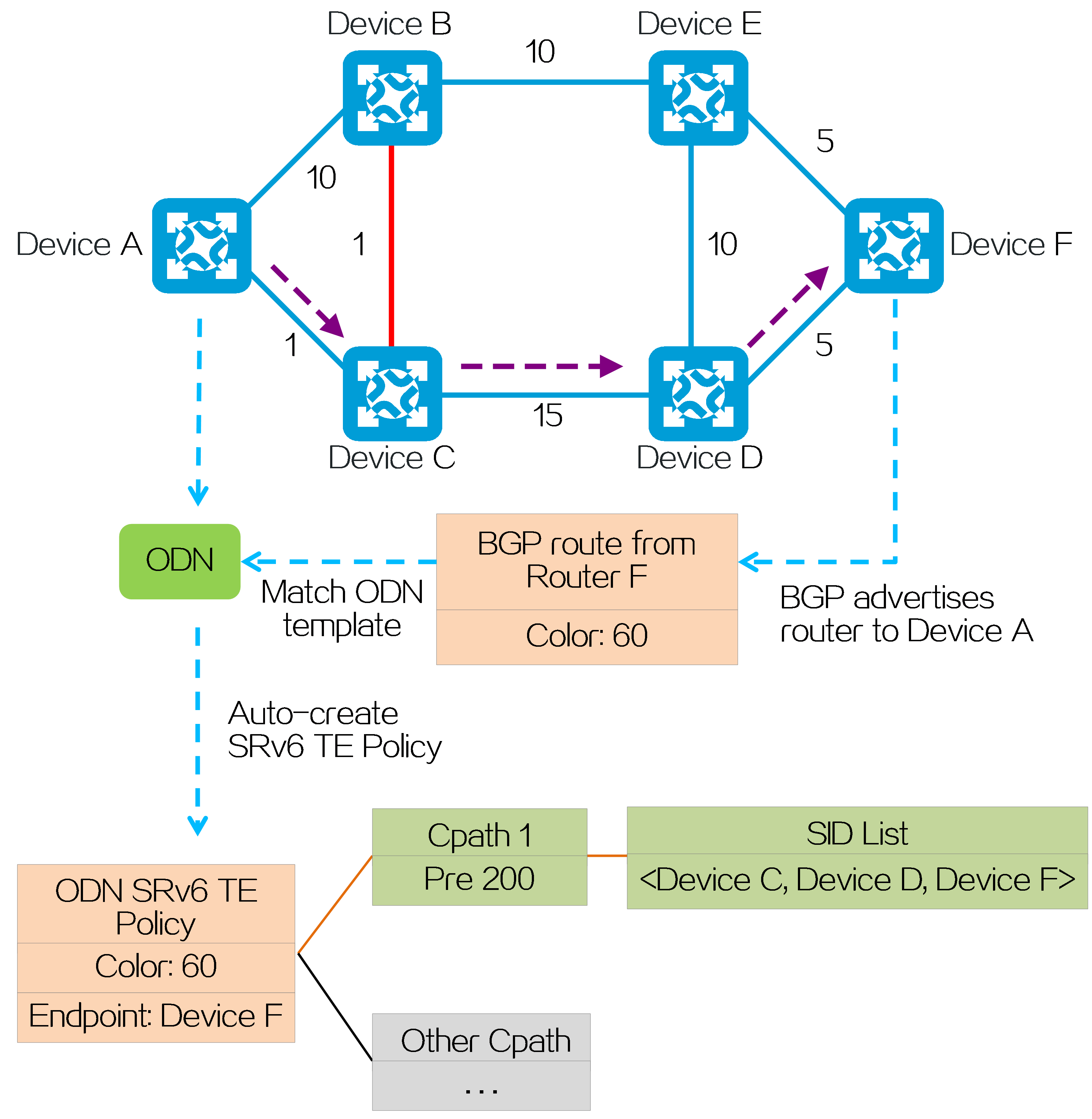
(2) Device A automatically creates an SRv6 TE policy after receiving a BGP route whose Color attribute value matches the ODN template. The SID list for the candidate path with a preference of 200 is dynamically calculated by Flex-Algo as <Device C, Device D, Device F>. When traffic from Device A to Device F is steered into the SRv6 TE policy, the traffic is forwarded along the purple path in the preceding figure.
4.15 Slice ID-based network slicing
Introduction
In the 5G and cloud era, operators and enterprises adopt network slicing technologies to virtualize a shared physical network into multiple logical networks to provide services for different tenants. In this way, they meet the differentiated requirements of various rapidly emerging services for network functions.
Slice ID-based network slicing is a network slicing technology applied in SRv6 network scenarios. It uses a globally unique slice ID to identify each virtual logical network and achieve network slicing functionality.
Slicing implementation
To divide a physical network into virtual network slices:
(1) Plan slice IDs: Allocate different slice IDs to different network slices according to service requirements.
(2) Map physical devices to virtual network slices based on slice IDs: Create network slice instances on physical devices. Each network slice instance is identified by a slice ID. In this way, the physical devices can be mapped to the virtual network slices corresponding to the slice IDs.
(3) Map physical interfaces to virtual network slices based on slice IDs: Enable network slicing on physical interfaces and create network slice channels on the interfaces. The identifier of a network slice channel is a slice ID. In this way, the physical interfaces can be mapped to the virtual network slices corresponding to the slice IDs. Different network slice channels on the same physical interface have independent queue scheduling and bandwidth guarantee mechanisms, so service traffic forwarding in one network slice channel does not affect that in another network slice channel.
(4) Network slice instances and channels with the same slice ID form a virtual network slice.
Figure110 Slice ID-based network slicing
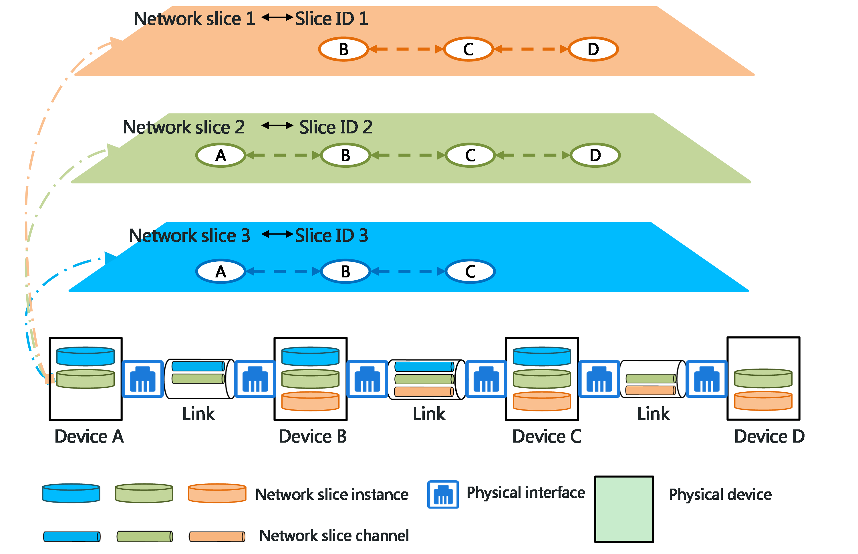
Packet forwarding mechanism
Packet structure
In the network that adopts slice ID-based network slicing technology, IPv6 packets carry a Hop-by-Hop Extension Header (HBH extension header), which contains slice ID information. The slice ID in the HBH extension header of a packet is used to identify the network slice to which that packet belongs. All network devices that a packet passes through will identify the network slice to which that packet belongs based on the slice ID in the HBH header of that packet and forward that packet through the network slice channel identified by the slice ID.
Figure111 Structure for packets with the IPv6 HBH header and the slice ID option
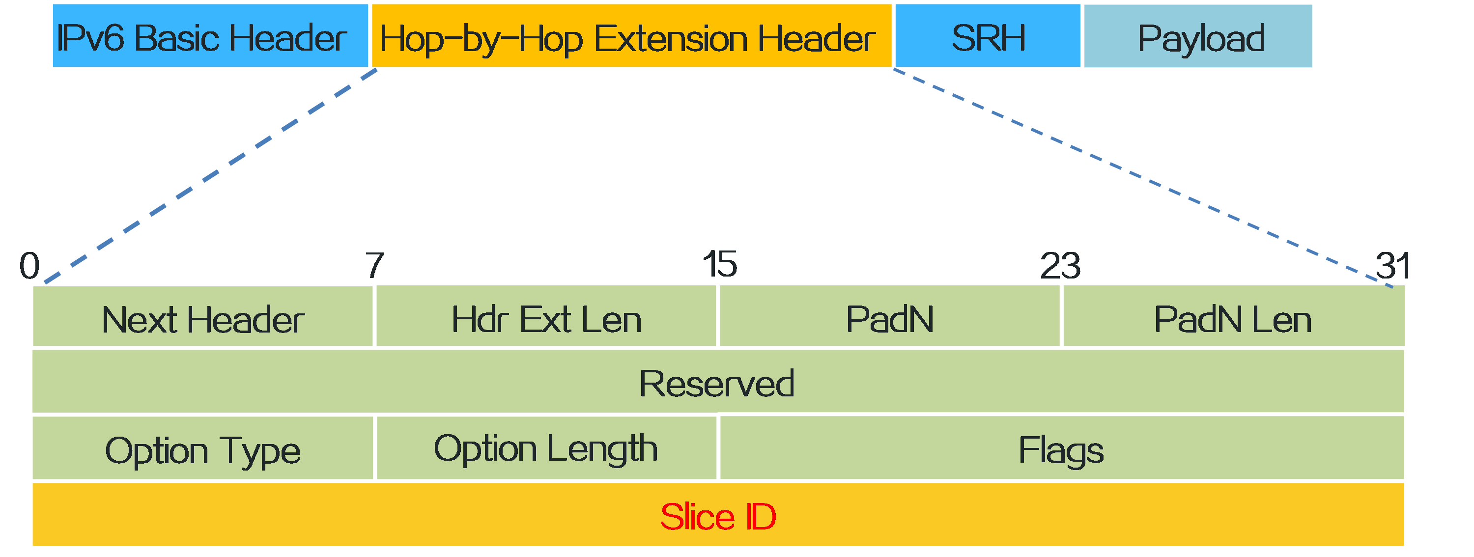
|
In the network, only the tunnel ingress and egress nodes are required to support SRv6. However, all devices must support slice IDs. |
Packet forwarding process
In the IPv4 L3VPN over SRv6 TE policy network as shown in the figure, network slices with slice ID 1 and slice ID 2 exist. PE 1, P, and PE 2, as well as their physical forwarding interfaces, are all mapped to network slice with slice ID 1 and network slice with slice ID 2. VPN service packets are steered to the SRv6 TE policy tunnel for forwarding.
To forward specific packets only within one network slice, you must associate the SRv6 TE policy with the slice ID of that network slice, so that these packets can be steered to the SRv6 TE policy and encapsulated with the slice ID information. The following methods are used to associate an SRv6 TE policy and a slice ID:
· Manually associate a candidate path in an SRv6 TE policy with a slice ID.
· The local device learns associations between SRv6 TE policies and slice IDs from the BGP SRv6 policy routes advertised by peers.
The forwarding process for packets in a sliced network is as follows:
(1) CE 1 sends IPv4 unicast packets to PE 1. After PE 1 receives the packets sent by CE 1, it looks up the VPN instance routing table and finds that the output interface for the matching route is the SRv6 TE policy. Then, PE 1 encapsulates the following information to the packets:
· The SRH header that contains the SID list of the SRv6 TE policy.
· The HBH extension header that carries slice ID 1 associated with the SRv6 TE policy.
· IPv6 basic header.
(2) PE 1 forwards the packets to P. In this process, PE 1 searches for the output interface based on the destination address of the packets (the address of P), finds the network slice channel associated with the slice ID on the output interface, and then forwards the packets through that channel.
(3) P changes the destination address of the packets to the address of PE 2 according to the SRH header. Then, P searches for the output interface based on the destination address of the packets and forwards the packets through the network slice channel associated with slice ID 1 on the output interface.
(4) After the packets arrive at the egress node PE 2, PE 2 looks up the local SID table based on the IPv6 destination address of the packets. If the IPv6 destination address matches an End SID, PE 2 decreases the SL value in the SRH of the packets by 1, and updates the IPv6 destination address to an End.DT4 SID. PE 2 looks up the local SID table based on the End.DT4 SID and performs the forwarding action corresponding to the End.DT4 SID. That is, PE 2 decapsulates the packets by removing the outer IPv6 header (including the HBH and SRH), looks up the routing table of the matching VPN instance based on the End.DT4 SID, and then forwards the packets to CE 2.
Figure112 Forwarding process of network slice packets
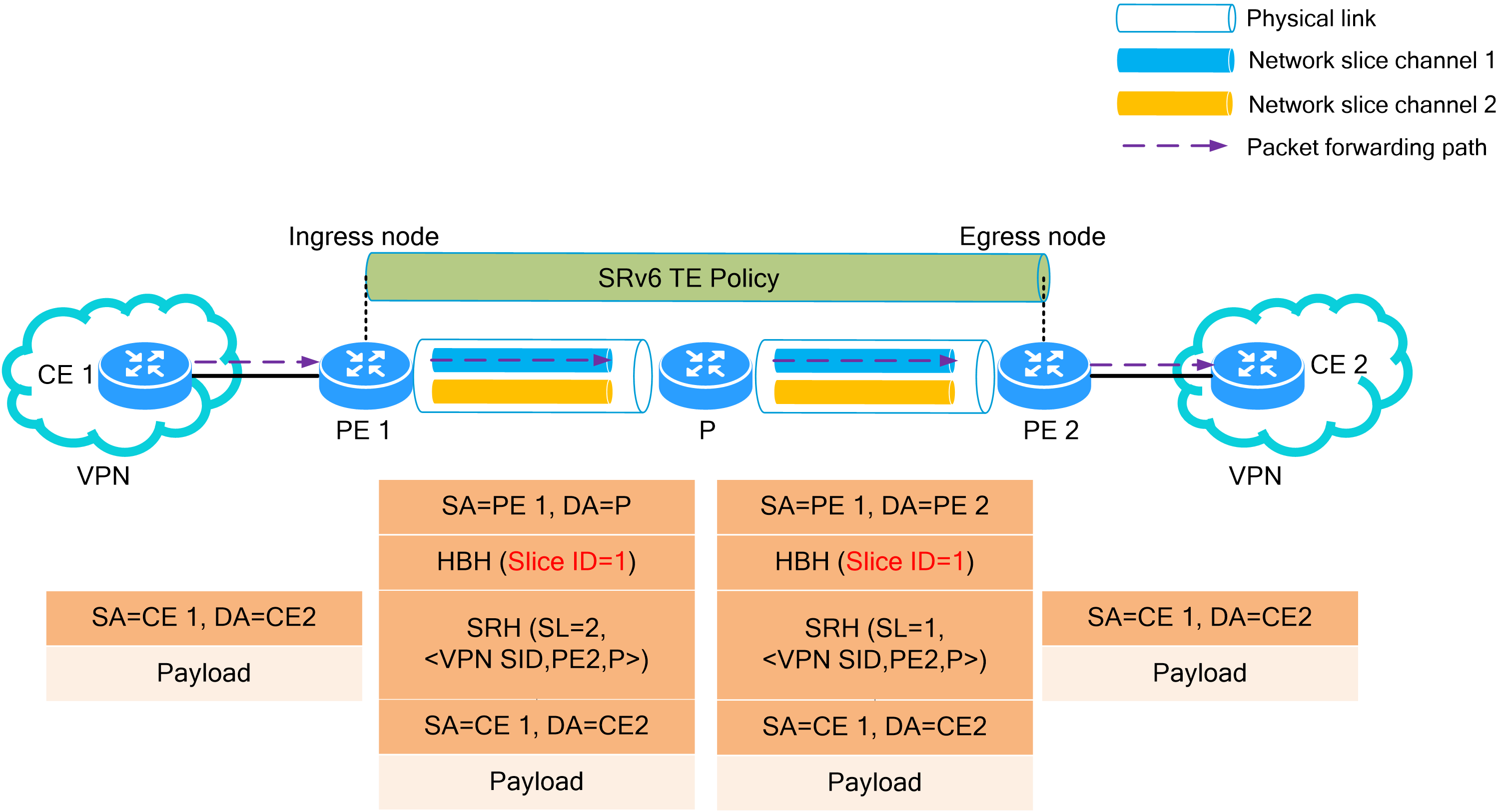
Advantages
The slice ID-based network slicing technology is applicable to SRv6 network environments and caters to the future development trend of SDN networks.
The slice ID-based network slicing technology has the following advantages:
· Simplified configuration and implementation—The configuration process is simple. By using the IP addresses of the physical network and the slice IDs of the network slices, this technology can isolate packet forwarding for different network slices. All network slices only require one set of IP addresses, avoiding wasted IP addresses.
· Fine-grained control of bandwidth—The bandwidth value of a network slice channel on a physical interface is small and can be finely controlled. Compared to FlexE technology's granularity of 1 Gbps, the minimum bandwidth value supported by the product for a network slice channel is 1 Mbps.
· Rich interface types—Interfaces that support network slice channels include Layer 3 Ethernet interfaces, Layer 3 aggregate interfaces, Layer 3 aggregate subinterfaces, Layer 3 subinterfaces, and FlexE interfaces.
· Numerous slices—Currently, the device supports a maximum of 6000 network slices, which fully satisfy the existing service requirements.
Configuration examples
As shown in the figure, the bearer network of the operator provides autonomous driving and 4K/8K high-definition IPTV services. The physical network is divided into two network slices by slice ID-based network slicing technology. Each of the network slices carries one type of service. The network slices provide different QoS quality assurance for different services.
· Assign sufficient bandwidth to the network slice with slice ID 1 for it to support 4K/8K HD IPTV services and ensure bandwidth guarantee for the services.
· Assign the edge computing DC to the network slice with slice ID 2, and connect it directly to the ring. The network slice with slice ID 2 supports the autonomous driving service and provides ultra-low latency assurance for the service through the edge computing DC.
Figure113 Application scenario of slice ID-based network slicing
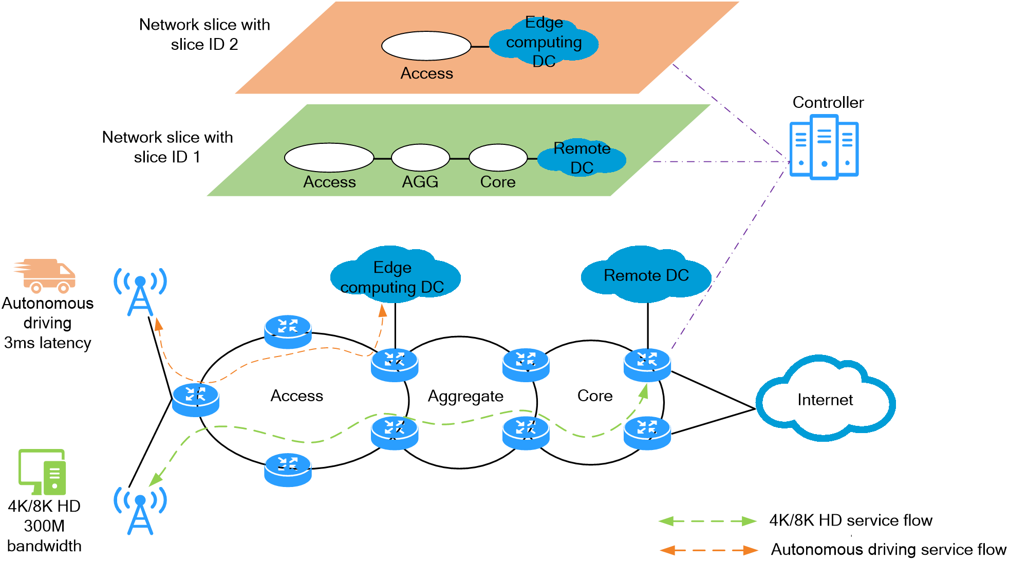
4.16 iFIT
About iFIT
In-situ Flow Information Telemetry (iFIT) determines network performance by measuring SLA parameters (including packet loss, packet delay, jitter, and real-time traffic) of service flows on an MPLS, SR-MPLS, or SRv6 network. Based on RFC 8321, iFIT is easy to deploy and provides an accurate assessment of network performance.
Benefits
· Easy to deploy and intelligent O&M
You need to only configure iFIT measurement parameters on the ingress point and enable iFIT on points to be measured. Then, the egress point and transmit points and will automatically perform the measurement and report the results. Transmit points might not support iFIT or are enabled with iFIT.
· High measurement accuracy
iFIT directly identifies service packets and measures the performance of service flows compared to technologies such as NQA that implement measurement by simulating service packets. The statistical data obtained by iFIT can truly reflect network quality, providing more accurate measurement results.
· Multiple application scenarios
iFIT supports MPLS, SR-MPLS, and SRv6 networks. It also supports scenarios such as single point-to-point, single point-to-multipoint, and multipoint-to-multipoint.
· Quick troubleshooting and precise fault location
iFIT supports simultaneous end-to-end and hop-by-hop measurements, allowing for faster troubleshooting and more accurate fault location compared to the method of identifying packet loss and then sequentially tracing faults hop by hop.
Network model
iFIT uses a network model that collects data from multiple points and performs centralized analysis by using a single analyzer. This model contains the following elements:
· Ingress point: The ingress point refers to the point that the flow enters the measurement network. It filters the target flow, adds iFIT headers to the packets of the flow, collects packet statistics and reports packet statistics to the analyzer.
· Transmit point: A transmit point automatically identifies the target flow by the iFIT header and reports the measurement statistics to the analyzer according to the measurement mode in the iFIT header.
· Egress point: The egress point refers to the point that the flow exits the measurement network. It identifies the target flow by the iFIT header, reports the measurement statistics to the analyzer, removes the iFIT header from the packet, and sends the target flow to the next hop.
· Analyzer:The analyzer collects the statistics reported by the ingress point, transmit points, and egress point for data summarization and calculation.
· Target flow: A target flow is measured by iFIT and refers to a service flow in the network that matches a set of criteria. The administrator can define a target flow by combining parameters such as source IP address/subnet, destination IP address/subnet, protocol type, source port number, and destination port number.
· Measurement Point (MP): An MP is associated with a Layer 3 physical interface and is responsible for executing measurement actions and generating statistical data. Depending on their functions, MPs are categorized into Ingress MP (traffic ingress measurement point), egress MP (traffic egress measurement point), and transmit MP.
Figure114 iFIT network model
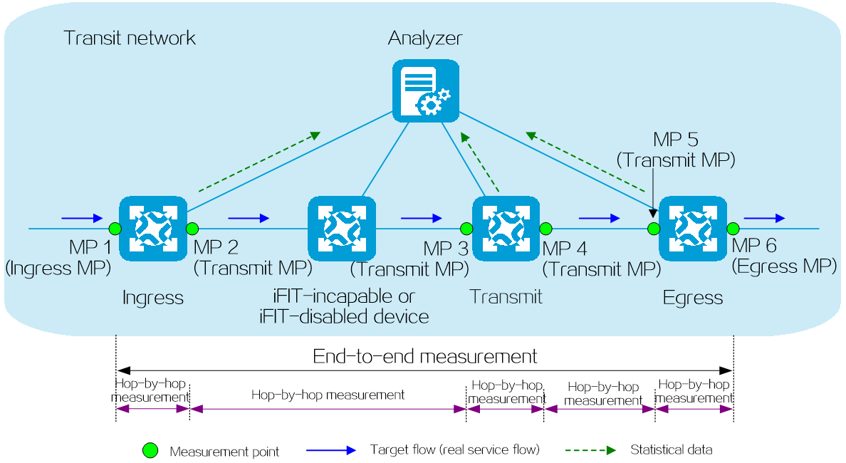
Application scenarios
End-to-end measurement
· Application scenario: Used for measuring the overall SLA of service traffic flowing between the ingress and egress points of a network.
· Measurement scope: Network SLA between the ingress MP and egress MP, for example, the SLA between MP1 and MP6 in the iFIT network model diagram.
· Advantages: iFIT does not need to be supported or enabled on devices as transmit points. This measurement is compatible with all available network devices, safeguarding user investments.
Hop-by-hop measurement
· Application scenario: Both the overall end-to-end SLA of the network and the SLA within any device or link in the network can be measured simultaneously.
· Measurement scope: SLA between any two MPs in the end-to-end network. For example, the SLA between MP2 and MP3 in the iFIT network model diagram can be measured.
· Advantages: You can simultaneously measure the SLA for end-to-end, device-level, and link-level performance, enabling quick troubleshooting and accurate fault location.
iFIT measurement mechanism
Packet loss measurement mechanism
To provide network administrators with timely information on packet loss, iFIT measures packet loss rate based on measurement periods. To differentiate packets between adjacent periods, iFIT utilizes period-alternating coloring technique. The packet loss measurement works as follows:
(1) The ingress MP colors packets for packet loss measurement.
iFIT uses the L field in the iFIT header of a packet as the coloring bit for packet loss measurement, setting it to 1 for coloring and 0 for no coloring. The ingress MP alternates between coloring and not coloring the target flow in each measurement period to differentiate packets between adjacent periods.
(2) Each MP periodically counts the number of received packets.
An MP separately counts the colored and non-colored packets received.
iFIT sets the packet reception statistics period longer than the packet transmission statistics period to minimize the adverse effects of network delays and packet reordering on the statistics. As shown in the following figure, the colored packet X is delayed but still included in the statistics period of colored packet reception.
At the transmitter side: Colored packet transmission statistics period = Non-colored packet transmission statistics period = iFIT statistics period (configurable).
At the receiver side: Colored packet reception statistics period = Non-colored packet reception statistics period = (1 + 1/3) iFIT statistics period.
The number of incoming packets and that of outgoing packets on a network should be equal within a statistics period. Therefore, in the i-th statistics period, the difference in the number of packets received by any two MPs is equal to the number of packets lost between these two MPs: PacketLoss[i] = Tx[i]–Rx[i].
(3) The egress MP forwards a packet to the next hop after removing the iFIT header of the packet.
Figure115 iFIT packet loss measurement mechanism
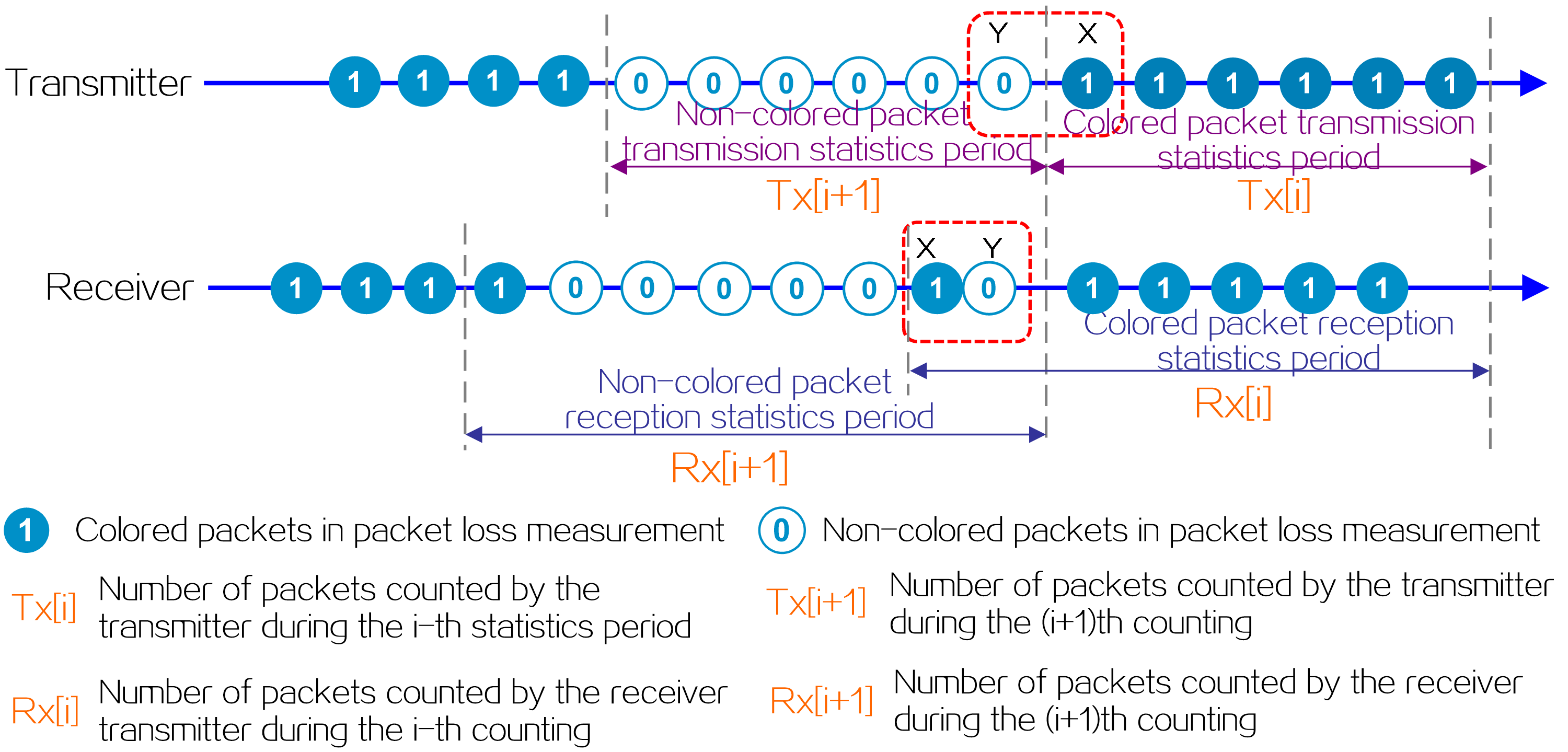
|
|
Packet delay measurement mechanism
iFIT performs delay measurement and packet loss measurement simultaneously, using the same period for coloring and statistics. The delay measurement works as follows:
(1) (1) The ingress MP applies delay coloring to packets.
iFIT uses the D field in the iFIT header of a packet as the delay measurement coloring bit, setting it to 1 for coloring and 0 for no coloring. The ingress MP applies delay coloring to the first packet received for each target flow within each statistics period. (The packets with the delay measurement coloring bit set to 1 will be referred to as delay coloring packets.)
(2) Each MP records the timestamp of the delay coloring packets passing through the MP.
In the i-th statistics period, the difference between the timestamps of any two MPs represents the transmission delay of the target packets between those two MPs: Delay[i] = t΄[i]-t[i].
(3) The egress MP forwards a packet to the next hop after removing the iFIT header of the packet.
Figure116 iFIT delay measurement mechanism
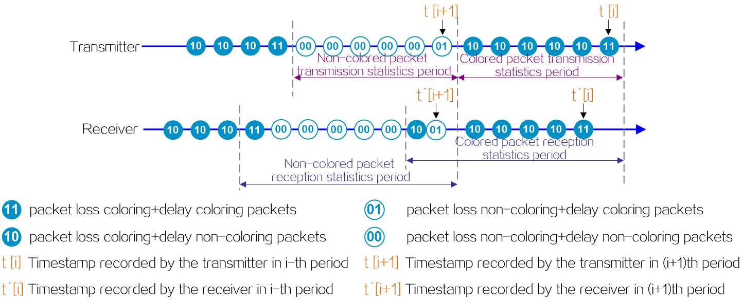
Measurement data reporting mechanism (Telemetry)
iFIT uses gRPC-based Telemetry to report statistics to the analyzer. Telemetry is a remote data collection technology for monitoring device performance and faults. In an iFIT network, iFIT devices act as gRPC clients, and the iFIT analyzer acts as a gRPC collector. The devices establish a gRPC connection with the analyzer in a gRPC dial-out mode and push the subscribed iFIT statistics to the analyzer.
Operating mechanism
iFIT works as follows:
(1) Time on all devices involved in the measurement is synchronized. If the time is not synchronized, the statistics periods of each MP will not be consistent, resulting in inaccurate iFIT calculation results. For ease of management and maintenance, synchronize the time between the analyzer and all iFIT devices as a best practice.
¡ For iFIT measurement on only packet loss, you can use NTP for time synchronization (to accuracy at the second level).
¡ For iFIT measurement on the delay, use PTP for time synchronization (to accuracy at the sub-microsecond level).
(2) The devices collect the statistical data generated by MPs periodically and report it to the analyzer through Telemetry.
(3) The analyzer performs packet loss analysis on the same target flow within the same statistics period and calculates parameters such as delay and delay jitter.
As shown in the following figure, each node uses PTP for time synchronization and measures both packet loss and delay parameters.
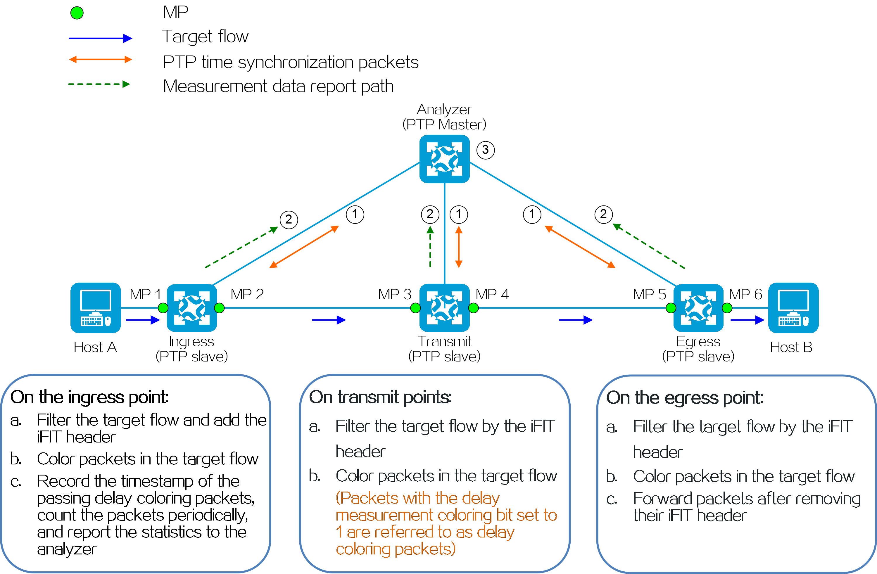
Typical network models
E2E SR-MPLS (Option A)
On an E2E SR-MPLS (Option A) network as shown in the following figure, severe mosaic and discontinuity issues have occurred in the video calls between enterprise network users. It is necessary to identify the locations where packet loss and delay occur during the transmission of video call traffic on the network.
The administrator deploys iFIT on both AS 1 and AS 2. For example:
· If PE 1, P 1, and ASBR 1 all support iFIT, configure hop-by-hop measurement on these devices to simultaneously monitor the SLA for the target flow passing through each device, each link, and the entire AS 1.
· If P 1 does not support iFIT, configure end-to-end measurement on PE 1 and ASBR 1 to monitor the SLA for the target flow passing through AS 1.
Figure118 iFIT for an E2E SR-MPLS (Option A)
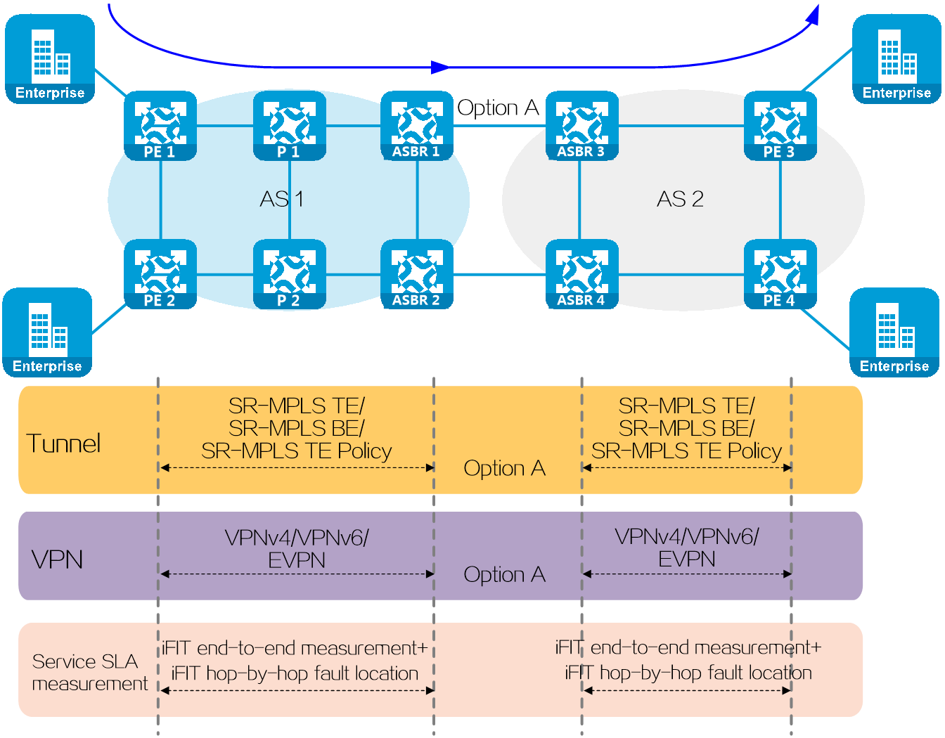
L3VPN over SRv6
On an E2E SR-MPLS (Option A) network as shown in the following figure, severe mosaic and discontinuity issues have occurred in the video calls between enterprise network users. It is necessary to identify the locations where packet loss and delay occur during the transmission of video call traffic on the network.
The administrator deploys iFIT on the SRv6 network. For example:
· If PE 1, P, and PE 2 all support iFIT, configure hop-by-hop measurement on these devices to simultaneously monitor the SLA for the target flow passing through each device, each link, and the entire SRv6 network.
· If P does not support iFIT, configure end-to-end measurement on PE 1 and PE 2 to monitor the SLA for the target flow passing through the SRv6 network..
Figure119 iFIT for an L3VPN over SRv6 network
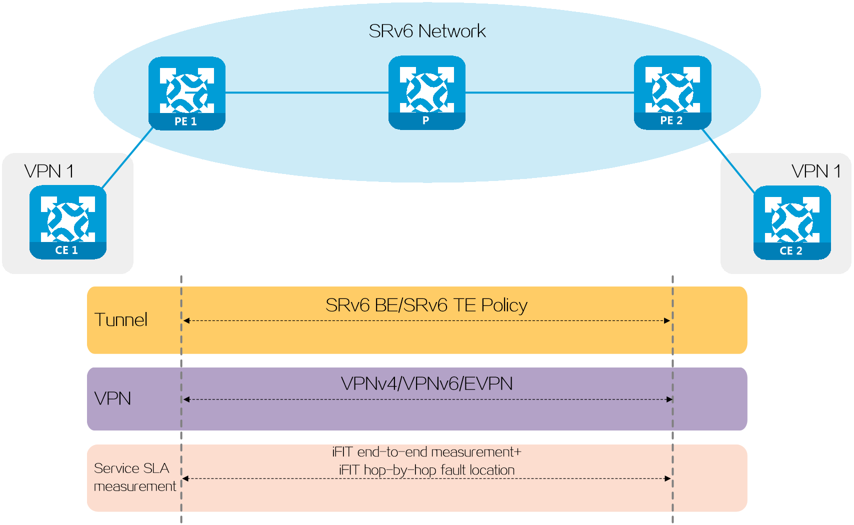
4.17 G-BIER
Introduction
Bit Index Explicit Replication (BIER) is a new architecture for the forwarding of multicast data packets. BIER encapsulates the destination nodes of multicast packets in a bit string. It does not require a protocol for explicitly building multicast distribution trees, nor does it require intermediate nodes to maintain any per-flow state.
Generalized Bit Index Explicit Replication (G-BIER) is a standard of China Mobile. By revising the standard BIER header defined in the RFC, G-BIER achieves better integration between the BIER network and IPv6 network.
Figure120 G-BIER network
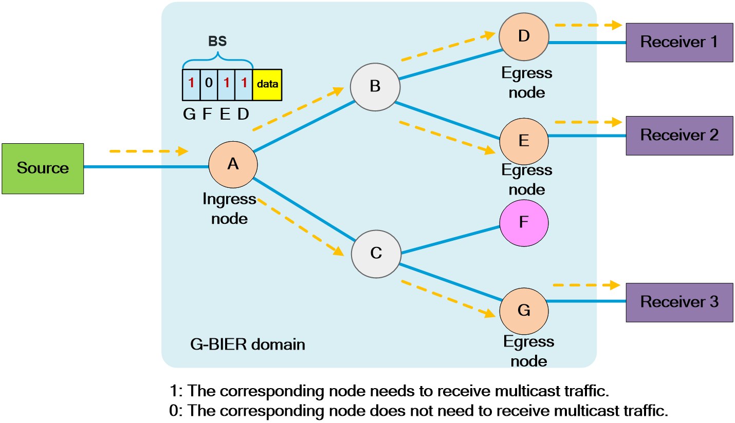
Technical advantages
· Simplified control plane
On the intermediate nodes, there is no need to run PIM and MPLS protocols. The control-plane protocols are unified as unicast routing protocols IGP and BGP, simplifying the deployment of control-plane protocols on the network.
· Facilitating the evolution of SDN architecture
Deployment of multicast services does not require the operation of intermediate nodes in the network. Only the G-BIER encapsulation needs to be added to the multicast packets at the ingress node for subsequent multicast replication. The G-BIER encapsulation carries a bit string identifying the multicast egress nodes. Intermediate nodes replicate and forward the multicast traffic based on the bit string, facilitating the evolution of SDN networks.
· Suitable for large-scale multicast service deployment
G-BIER does not need to establish multicast distribution trees for each multicast flow or maintain multicast per-flow state. It only needs to build a Bit Index Forwarding Table on each node on the forwarding path to achieve BS-based packet forwarding, eliminating the pressure on networks caused by large-scale deployment of multicast services.
· Support for multicast VPN architecture
In the Next Generation Multicast VPN (NG MVPN) service, the G-BIER tunnel can replace RSVP TE P2MP and mLDP P2MP tunnels. It serves as a public network tunnel to encapsulate multicast private network traffic and deliver it to other nodes within the G-BIER domain.
Network model
A router that supports BIER is known as a Bit-Forwarding Router (BFR). A G-BIER network consists of the following BFRs:
Figure121 G- BIER network model
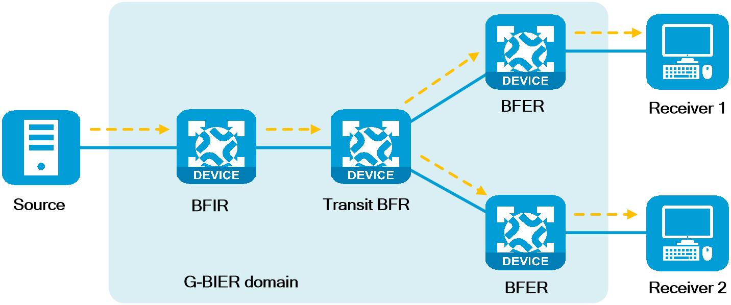
· Bit Forwarding Ingress Router (BFIR)—A multicast data packet enters a BIER domain at a BFIR. A BFIR encapsulates the multicast data packet as a G-BIER packet. Each BFIR is uniquely identified by a BFR ID.
· Transit BFR—A transit BFR forwards a multicast data packet from one BFR to another BFR in the same G-BIER domain. A transit BFR does not need to have a BFR ID.
· Bit Forwarding Egress Router (BFER)—A multicast data packet leaves a BIER domain at a BFER. A BFER decapsulates the multicast data packet and sends it to multicast receivers. Each BFER is uniquely identified by a BFR ID.
· G-BIER edge device—Both BFIRs and BFERs are referred to as G-BIER edge devices.
· G-BIER domain—A routing domain or administrative domain that contains a group of BFRs. A G-BIER domain can contain one or more sub-domains. Each sub-domain is uniquely identified by a sub-domain ID.
Packet encapsulation
A G-BIER packet consists of an IPv6 basic header, an IPv6 extension header (Destination Options Header (DOH)), and the original multicast data packet. The G-BIER header is encapsulated in the DOH.
Figure122 G-BIER encapsulation format
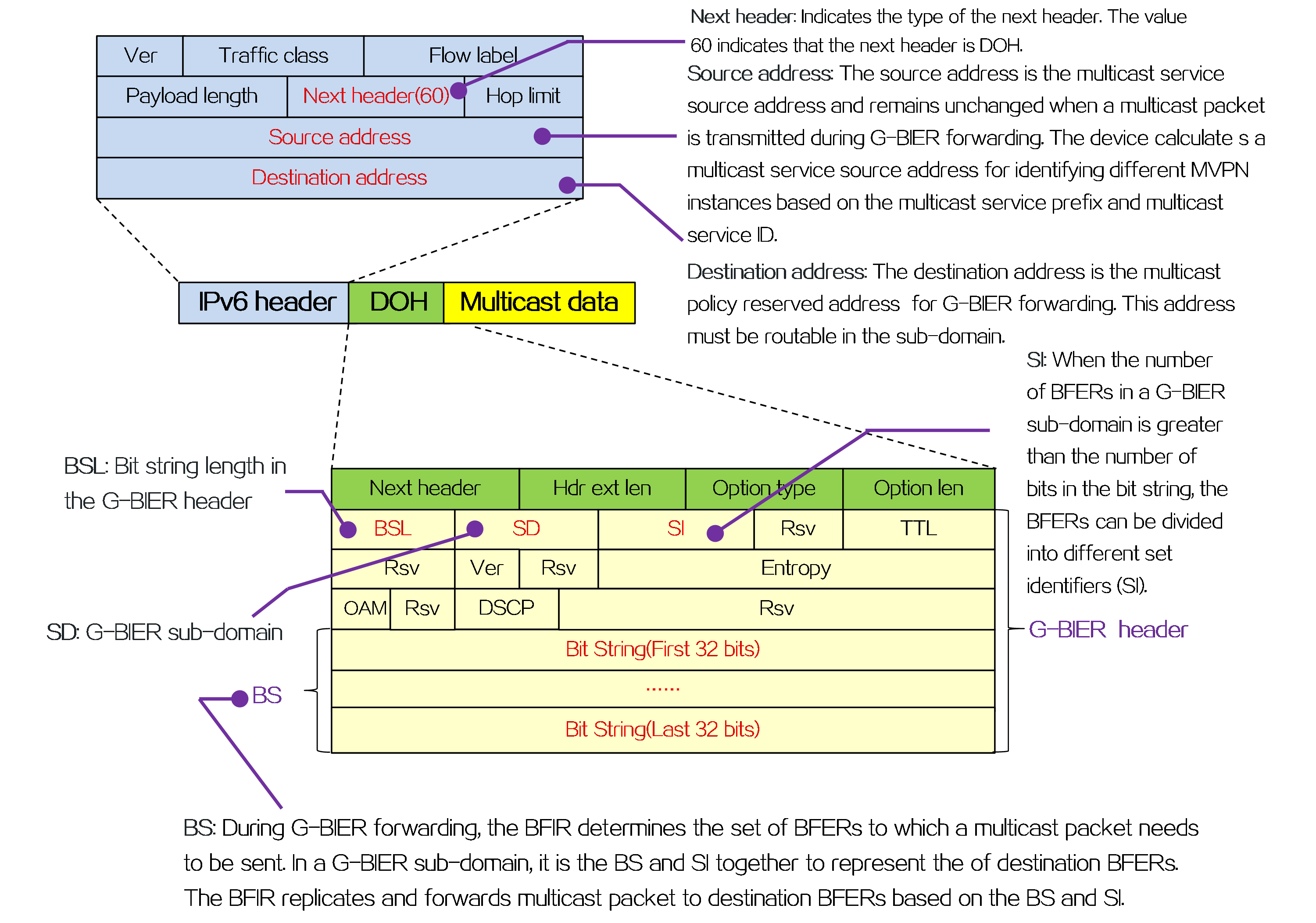
Three-layer network architecture
The G-BIER network architecture consists of three layers: underlay, G-BIER layer, and overlay, as shown in the diagram below.
Figure123 G-BIER three-layer network architecture
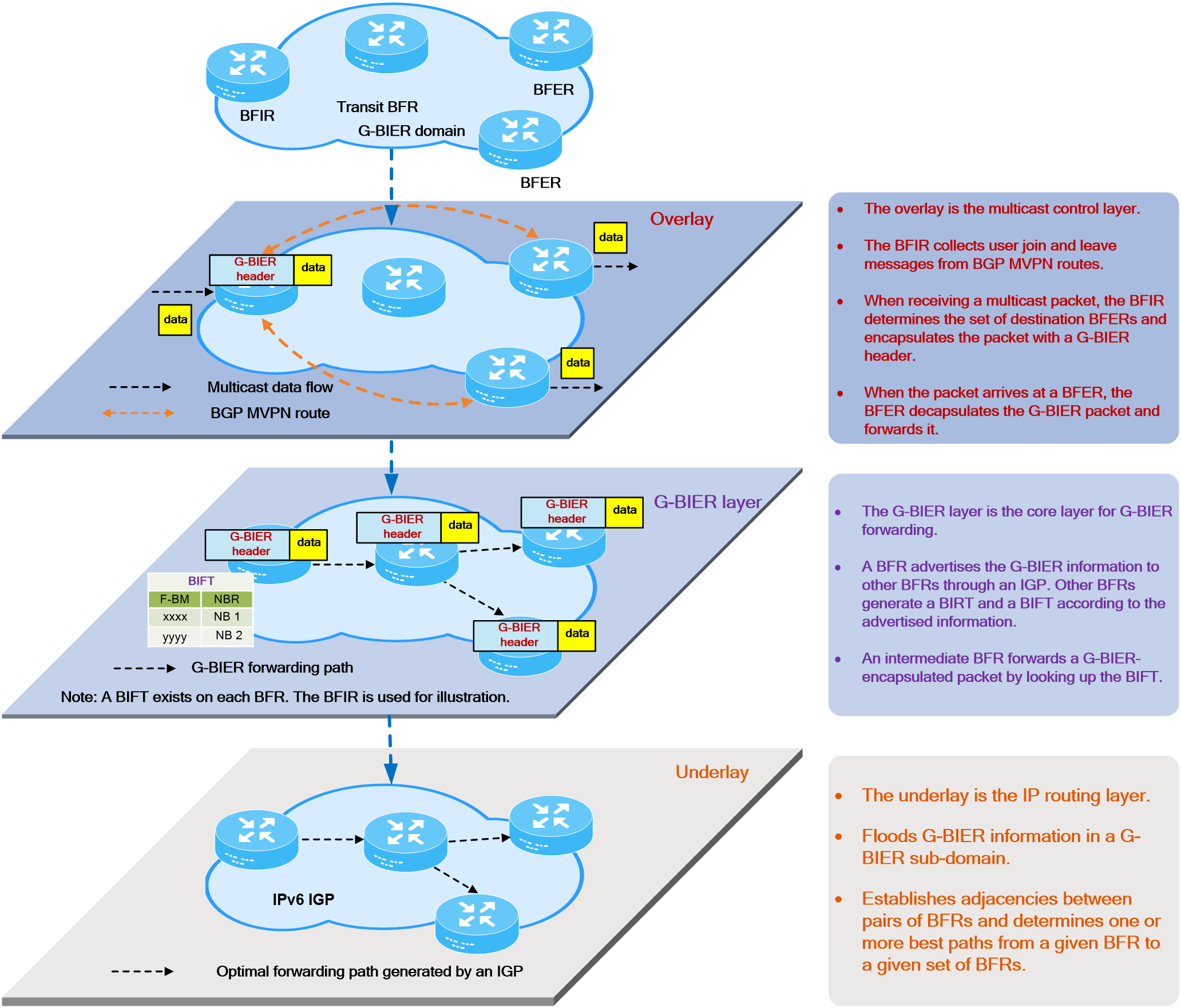
G-BIER forwarding process
Basic concepts
· The Forwarding Bit Mask (F-BM) represents a set of edge nodes in a G-BIER sub-domain that are reachable through a BFR neighbor (BFR-NBR) on the optimal path. The bit mask is obtained by taking the logical OR of the bit strings corresponding to the reachable edge nodes.
· The Bit Index Forwarding Table (BIFT) is used to guide the per-hop forwarding of multicast traffic in a G-BIER sub-domain. Each BIFT entry records the corresponding F-BM and BFR-NBR. Each BIFT is uniquely identified by a BIFT ID. A BIFT ID is a combination of the BSL, sub-domain ID, and set identifier (SI).
· Bit string (BS): During G-BIER forwarding, the BFIR determines the set of BFERs to which a multicast packet needs to be sent. In a G-BIER sub-domain, it is the BS and SI together to represent the of destination BFERs. The BFIR replicates and forwards multicast packet to destination BFERs based on the BS and SI and the F-BM.
Forwarding process
(1) When a multicast packet arrives, the BFIR looks up the multicast forwarding table to determine that this packet needs to be forwarded using G-BIER, and obtains the BIER forwarding information (BIFT ID and BS). BIER forwarding information is generated through BGP MVPN routing interaction between the BFIR and BFER. As shown in the figure below, Device A learned via BGP MVPN routing that there are receivers downstream of Device D, Device E, and Device F. The BS value 0111 obtained is the result of performing a bitwise OR calculation on the bit positions corresponding to the BFR IDs of Device D, Device E, and Device F.
Figure124 G-BIER forwarding process (1)
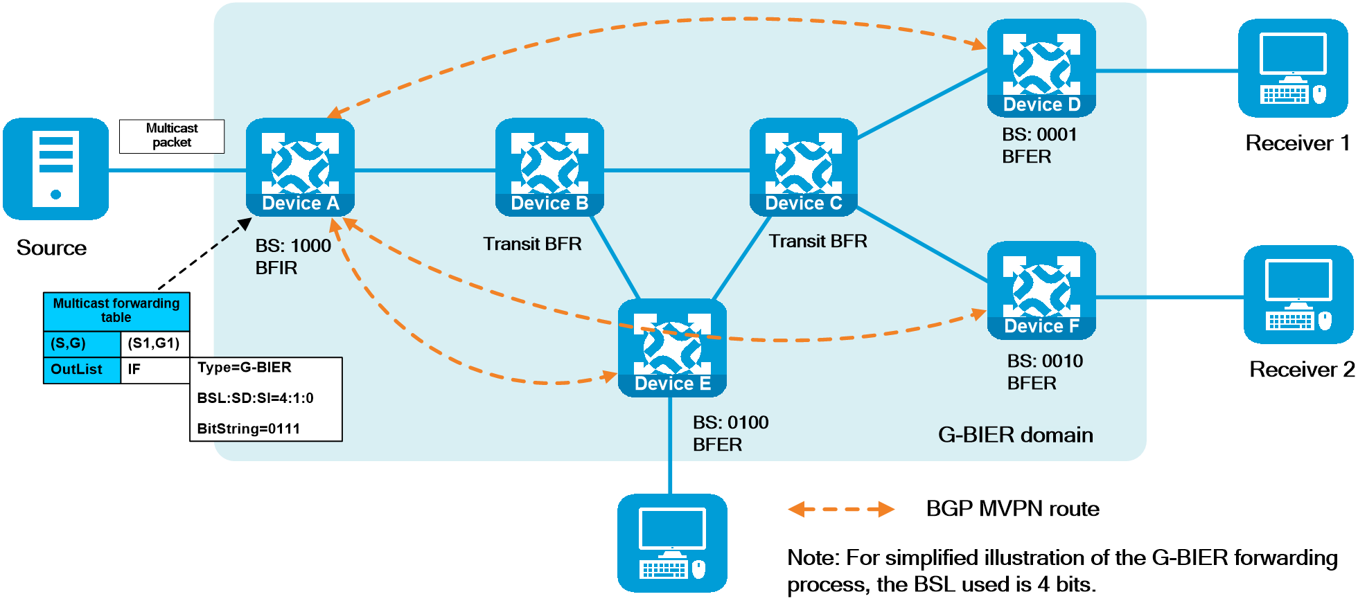
(2) BFIR performs "bitwise AND" calculations between the BS and F-BM in the BIFT one by one. If the resultant BS is not all zeros, a copy of the packet is encapsulated according to the G-BIER packet encapsulation format and sent to the next-hop neighbor corresponding to that entry. The encapsulated BS value is the calculated value, the destination address is the next-hop neighbor's MPRA, and the source address is the multicast service source address. As shown in the figure below, the BS value 0111 is ANDed with each F-BM in the BIFT on Device A. It is found that only the F-BM corresponding to Device B does not become 0 after the ANDing operation. Therefore, only one copy of the multicast packet will be duplicated and sent to Device B after G-BIER encapsulation. The encapsulated BS value 0111 is obtained after the ANDing operation.
|
l As hown in the figure below, the F-BM corresponding to Device B in the BIFT on Device A is 0111, indicating that the G-BIER edge nodes that can be reached through the next-hop neighbor Device B on the optimal path are Device D, Device E, and Device F. The F-BM value 0111 is the bitwise OR calculation result of the bit positions corresponding to the BFR IDs of all G-BIER edge nodes that can be reached through Device B on the optimal path. l Multiple BIFTs exist on a BFR, and each BIFT for guiding G-BIER forwarding is uniquely identified by the triplet information (BSL, sub-domain ID, SI) in the G-BIER packet. |
Figure125 G-BIER forwarding process (2)
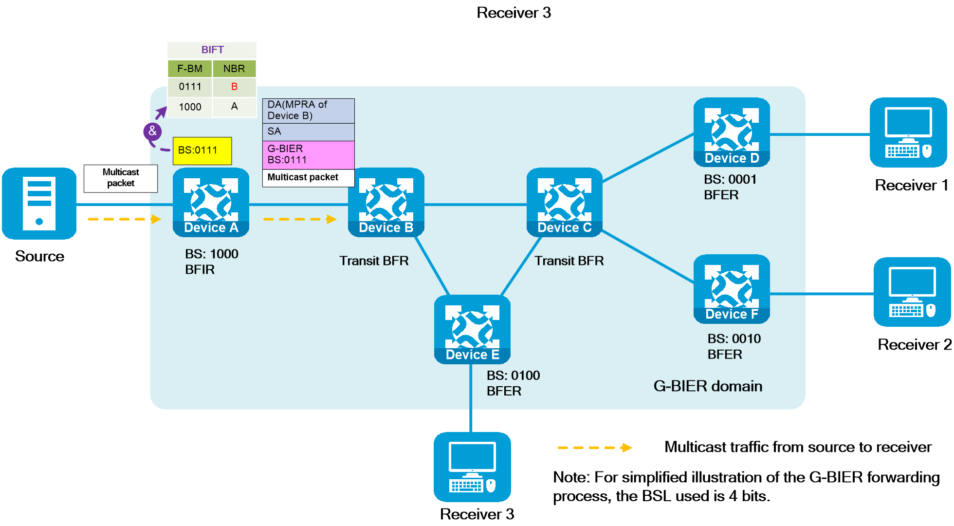
(3) A transit BFR matches the destination address in the received G-BIER packet header with the configured MPRA on the local device.
· If there is a match, the transit BFR performs G-BIER forwarding. The transit BFR performs the same operation as in step 2 and forwards the packet according to the BIFT to the next-hop neighbor. The source address encapsulated in G-BIER remains unchanged during the forwarding process. As shown in the figure below, the BS value 0111 is ANDed with each F-BM in the BIFT on Device B. It is found that only the F-BMs corresponding to Device C and Device E are not 0 after the ANDing operation. Therefore, one copy of the multicast packet will be duplicated and sent to Device C and Device E after G-BIER encapsulation. The encapsulated BS value is 0011 for the packet sent to Device C. The encapsulated BS value is 0100 for the packet sent to Device E. The forwarding process on Device C is similar to Device B, and no further explanation is needed.
· If there is no match, regular IP forwarding is performed.
|
|
Figure126 G-BIER forwarding process (3)
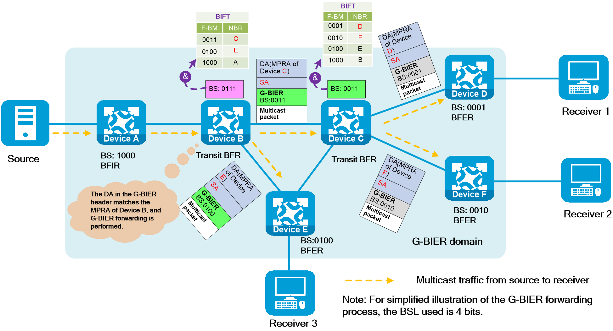
(4) After receiving the G-BIER packet, the BFER needs to terminate G-BIER forwarding. The BFER first decapsulates the G-BIER header to obtain the original multicast packet, then looks up the corresponding multicast forwarding table based on the MSID in SA, and forwards the multicast packet to the final multicast receiver according to the multicast forwarding table.
|
|
As shown in the figure below, taking Device D as an example, after bitwise AND calculations between BS value "0001" and each F-BM in the BIFT, it is found that only the F-BM corresponding to the current node has a non-zero result after the bitwise AND calculation with BS, indicating that Device D is a BFER and G-BIER forwarding needs to be terminated on Device D. At this time, Device D sends the multicast packet to downstream multicast receivers after encapsulating the G-BIER header and obtaining the multicast packet according to the multicast forwarding table. The operations on Device E and Device F are similar to those on Device D, and will not be repeated.
Figure127 G-BIER forwarding process (4)
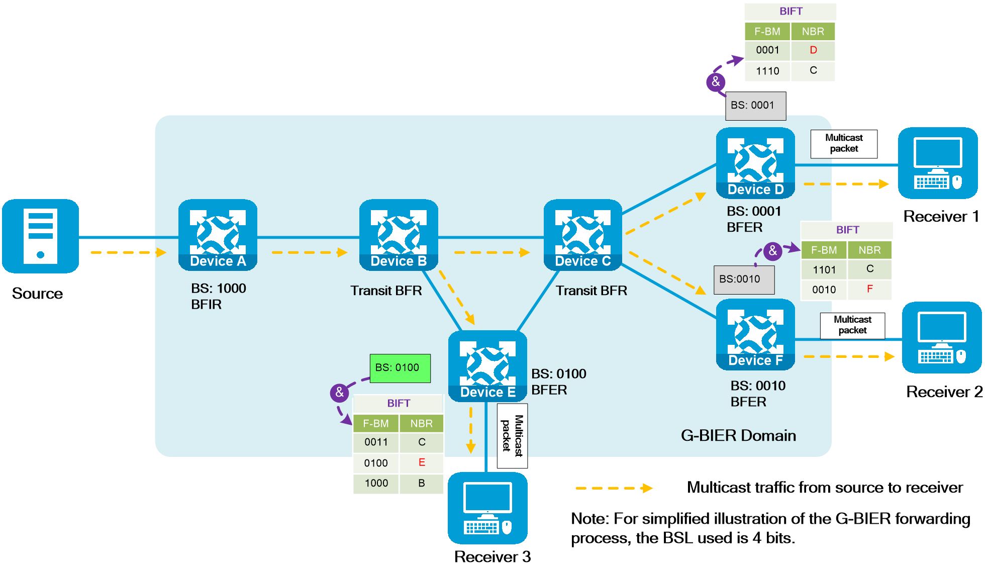
Application scenarios
NG MVPN over G-BIER is a typical application scenario that utilizes G-BIER technology. In this scenario, a bearer tunnel is established using G-BIER, and multicast private network traffic is encapsulated with G-BIER and sent through the public network to other nodes in a G-BIER sub-domain.
Networking model
The network model of NG MVPN over G-BIER is shown in the following figure.
Figure128 NG MVPN over G-BIER network model
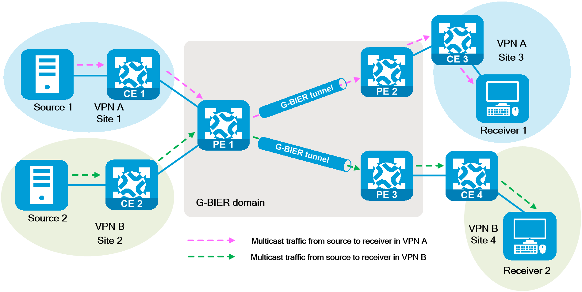
MVPN BGP protocol extension
In MVPN over G-BIER, the new BGP attribute MSID is used to identify the MVPN instance, and it carries the multicast service source address that identifies the MVPN instance.
(1) When the multicast source PE encapsulates multicast packets for G-BIER, the source address in the IPv6 basic header needs to be configured as the multicast service source address.
· The multicast service source address is generated by the multicast service prefix and multicast service ID value of the multicast source-side PE.
· In the process of forwarding multicast packets, the source address of the multicast service remains unchanged.
(2) The multicast source PE notifies the receiver-side PE of the multicast service source address by carrying the MSID attribute in the Intra-AS I-PMSI A-D route. The receiver-side PE records the mapping between the source address and the MVPN instance.
(3) When the receiver-side PE receives the multicast packet encapsulated in G-BIER, it will find the corresponding MVPN instance based on the multicast service source address in the packet, and forward the multicast packet according to the multicast forwarding table in the corresponding MVPN instance.
Operating mechanism
The operating mechanism of NG MVPN over G-BIER is as follows.
(1) The multicast source-side PE first interacts with the receiver PE through BGP MVPN routes to determine which receiver-side PEs the multicast traffic needs to be sent to.
(2) The multicast source-side PE and the receiver-side PE exchange G-BIER information (BFR ID, sub-domain ID, BFR prefix) between them through the Intra-AS I-PMSI A-D Route, S-PMSI A-D Route, and Leaf A-D Route carried in the BGP packets.
(3) Multicast data is transmitted from the CE to the PE via inclusive tunnels based on the PIM routing table, achieving seamless connection between private network and public network. The multicast source-side PE receives the private network multicast data, encapsulates it with a G-BIER header, and transmits it to the remote PE through an inclusive tunnel. After receiving the packet, the remote PE restores it to the private network multicast packet by stripping off the encapsulation information.
(4) When there is multicast traffic on the source-side PE that meets the criteria for selective tunnel switching, a selective tunnel is established with the corresponding remote PE, and the private network multicast data with a G-BIER header is transmitted through the selective tunnel.
Typical networking
Deploy G-BIER multicast service in the public network.
If multicast services are public services, the multicast source can be deployed in the public network. For example, the operator can provide on-demand services to residential/enterprise users connected to the provincial backbone network in various metropolitan area networks. Applying G-BIER technology in provincial backbone networks and metropolitan area networks can meet the fast joining requirements of multicast users and the rapid deployment needs of multicast services.
As shown in the figure below, the IPv6 provincial backbone and the IPv6 metropolitan area network are in different autonomous domains. The multicast source deployed in the public network is connected to the provincial backbone router (PB) through the provincial backbone service router (PSR), providing IPTV services from the operator's network to the end users in the metropolitan area network.
To ensure high service reliability, dual root hot backup mode is adopted. PSR 1 and PSR 2 are both G-BIER primary and backup roots, with multicast sources connected to Ethernet switches SW 1 and SW 2, respectively.
Figure129 Deploying G-BIER multicast service in the public network
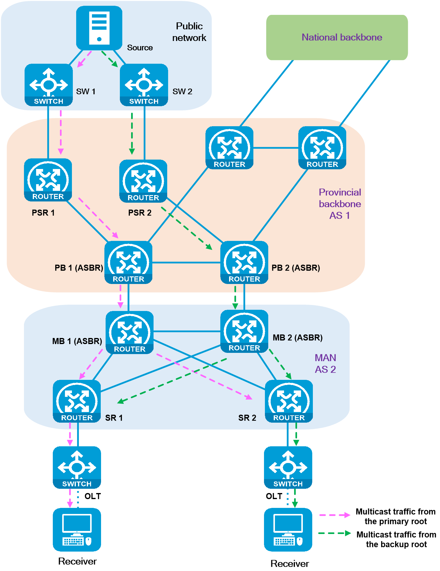
Deploy G-BIER multicast service in MVPN.
If there is a need for private multicast services in addition to public multicast services, deploy multicast sources in the VPN to which multicast users belong, and provide multicast services only to users in that VPN. Private multicast services are carried through the G-BIER tunnel of the operator's network, and can also achieve multicast service isolation between different VPNs. As shown in the diagram below, deploy multicast sources within VPN A to provide multicast services to multicast receivers within the same VPN A, located at local site (Site 2) and remote sites (Site 3 and Site 4).
Figure130 Deploying G-BIER multicast service in MVPN
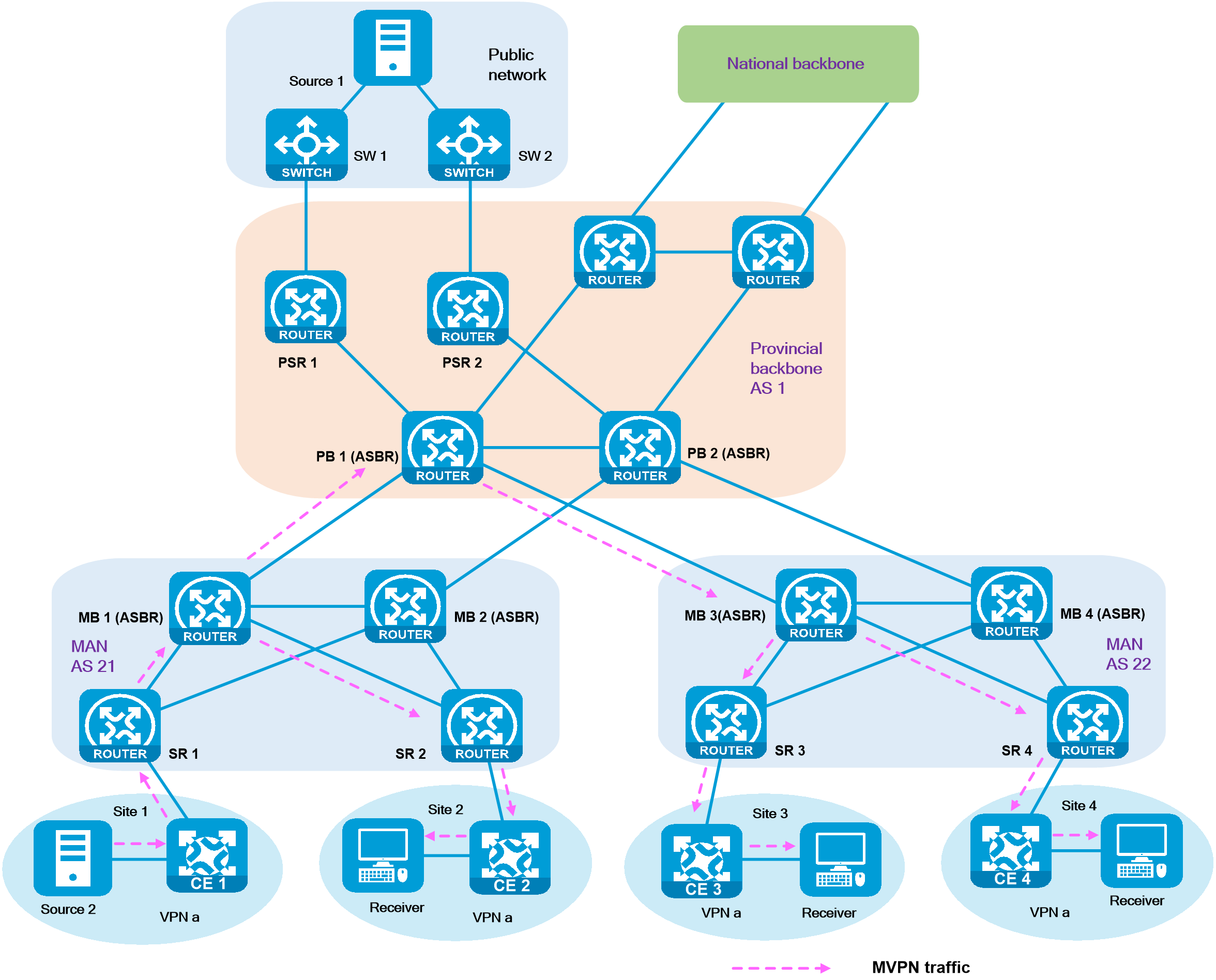
Advantages:
Applying G-BIER technology in the provincial backbone network and metropolitan area network can meet the fast joining of multicast users and the fast deployment of multicast services, without building a multicast distribution tree from the multicast source-side node to the multicast receiver-side node. Intermediate nodes do not need to run multicast routing protocols and maintain multicast forwarding states, which is suitable for large-scale deployment of multicast services by operators.
4.18 BIERv6
Background
Bit Index Explicit Replication (BIER) is a stateless and innovative multicast technology that addresses issues such as difficult network scalability, complex operations and maintenance management, and slow fault convergence in traditional multicast networks. It can efficiently distribute multicast packets. Due to the reliance of BIER on MPLS technology, its deployment in multicast services on non-MPLS networks requires an upgrade of all network devices, posing limitations.
With the flourishing development of IPv6 technology, in the unicast forwarding field, SRv6 technology based on the IPv6 data plane is developing rapidly, surpassing SR-MPLS based on the MPLS data plane. In the multicast field, it is an urgent problem to apply the BIER architecture to achieve the technology that does not rely on MPLS and conforms to the development trend of IPv6 networks. Against this backdrop, the industry has proposed Bit Index Explicit Replication IPv6 Encapsulation (BIERv6) technology based on IPv6.
Introduction
BIERv6 inherits the core design principles of BIER and encapsulates the set of multicast destination nodes as a bit string (BS) in the packet header. Intermediate nodes do not need to be aware of multicast services or maintain multicast flow state. They only need to replicate and forward multicast packets based on the BS in the packet header. BIERv6 combines the advantages of IPv6 scalability and uses IPv6 extension headers to carry information for guiding BIER forwarding, completely freeing itself from MPLS label forwarding mechanisms and facilitating the evolution and overlay of new services.
|
|
Technical advantages
The BIERv6 technology combines the BIER protocol with IPv6 packet forwarding, enabling seamless integration into SRv6 networks. It simplifies network protocols and reduces deployment complexity, effectively addressing future network development challenges.
· Simplified network protocols
BIERv6 uses the Bit Index Forwarding Table (BIFT) to guide the forwarding of MVPN and public multicast services, eliminating the need for allocation, management, and maintenance of MPLS labels.
· Simplified business deployment and maintenance
Intermediate nodes are not aware of multicast services, and the deployment of multicast services does not involve intermediate nodes. Changes in multicast services have no impact on intermediate nodes. When the network topology changes, there is no need to revoke and rebuild a large number of multicast distribution trees, which greatly simplifies network management and maintenance.
· High network reliability
BIERv6 forwards multicast data based on the BIFT. When there is a network failure, simply refresh the BIFT after route convergence at the underlay layer. Therefore, fault convergence is fast and network reliability is high.
· Support for multicast VPN architecture
In NG MVPN services, the BIERv6 tunnel can substitute RSVP TE P2MP and mLDP P2MP tunnels as a public tunnel to encapsulate multicast private network traffic via BIERv6 and send it to other nodes in the BIERv6 domain.
Key technologies
· IPv6 protocol extension
BIERv6 uses the IPv6 Destination Options Extension Header to carry the BIERv6 header. The new End.BIER SID is added as the destination IPv6 address to indicate the device's forwarding plane processing of the BIERv6 extension header in the packet.
· BIFT establishment process
In a BIERv6 sub-domain, multicast traffic is forwarded hop by hop by looking up the BIFT, which is the core of BIERv6 forwarding.
· Routing protocol extension
BIERv6 extended IS-IS and BGP protocols for flooding BIER information and carrying BIERv6 tunnel source addresses.
· BIERv6 forwarding process
Multicast packets are forwarded within the BIERv6 domain by looking up the BIFT lookup according to the BS in the packets. BIERv6 header encapsulation and decapsulation are performed at the ingress node and egress node, respectively.
IPv6 protocol extensions
BIERv6 packet format
BIERv6 fully utilizes the features of IPv6 extension headers, which do not require modification of existing packet structures when adding options. The BIERv6 header is carried in the Destination Options Header (DOH).
A BIERv6 packet consists of the IPv6 basic header, DOH, and the original multicast data packet, as shown in the following figure:
Figure131 BIERv6 packet format
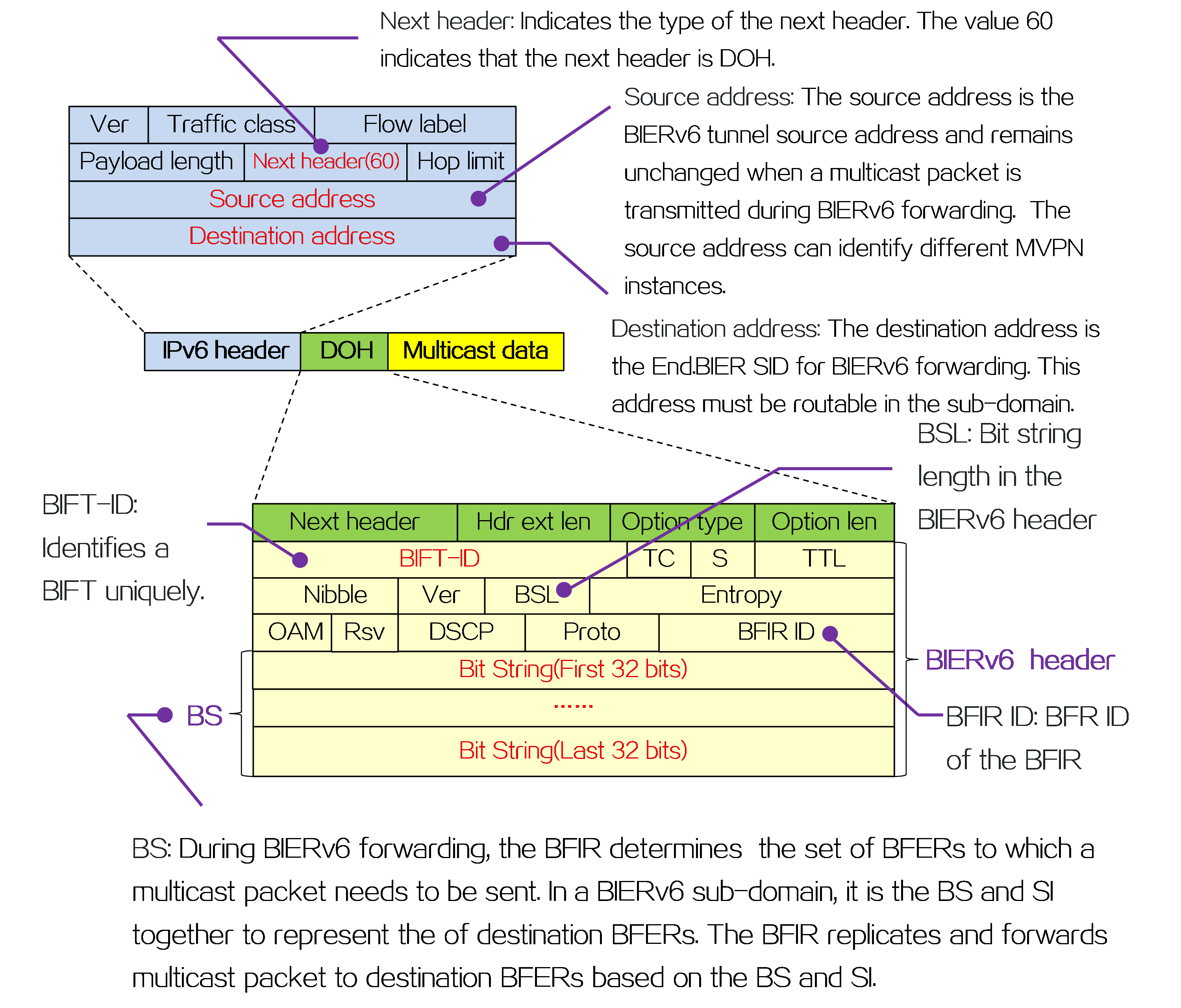
End.BIER SID
In BIERv6 networks, the End.BIER SID is a new type of SID defined as the End.BIER address. When the IGP protocol floods BIER information, it carries the address through the IS-IS sub-sub-TLV to notify other neighbors to use this IPv6 address as the destination IPv6 address when sending BIERv6 packets to the current node.
When a BFR receives a BIERv6 packet, it matches the destination IPv6 address of the BIERv6 packet with the locally configured End.BIER address.
· If the match is successful, it indicates that the BFR needs to perform BIERv6 forwarding for the packet.
· If the match fails, it means the BFR needs to perform regular IPv6 forwarding for the packet.
Routing protocol extensions
IS-IS BIERv6 extension
BIERv6 floods BIER information through the extended IGP protocol, and each node builds a BIFT to forward multicast data according to BIER information. The extension of IS-IS for BIERv6 is based on the extension of BIER and adds BIERv6 encapsulation information Sub-Sub-TLV and End.BIER Sub-Sub-TLV.
Table16 IS-IS BIERv6 extension
|
Type |
Name |
Role |
Carry location |
|
TLV |
IS-IS Reachability Prefix TLV |
Advertises the BFR prefix of the node. |
IS-IS packet |
|
Sub-TLV |
BIER Info Sub-TLV |
Advertises the BIER information (sub-domain ID and BFR ID) of the node. |
Type 237 TLV in IS-IS packets. |
|
Sub-Sub-TLV |
BIERv6 encapsulation information Sub-Sub-TLV |
Advertises the max-SI and BSL of the node. |
BIER Info Sub-TLV |
|
End.BIER sub-sub-TLV |
Advertises the End.BIER SID of the node. |
BIER Info Sub-TLV |
BGP BIERv6 extension
BIERv6 extends the Intra-AS I-PMSI A-D route (type-1 route) and the S-PMSI A-D route (type-3 route) in BGP MVPN routing. It carries the IPv6 source address encapsulated in the BIERv6 tunnel using the Prefix-SID attributes in the type-1 and type-1 routes. A BIERv6 tunnel source address can be used to identify an MVPN. The specific process is as follows:
(1) The multicast source-side PE announces the BIERv6 tunnel source address to the receiver-side PE by carrying Prefix-SID in the type-1 and type-3 routes.
(2) The receiver-side PE matches the local VPN instance or public network instance based on the Route Target attribute carried by the received type-1 and type-3 routes, and records the mapping between the Prefix-SID and the VPN instance or public network instance.
(3) When the receiver-side PE receives a multicast packet encapsulated with BIERv6, it will, based on the BIERv6 tunnel source address in the packet, find the corresponding VPN instance or public network instance. Then, it looks up the multicast forwarding table in the VPN instance or public network instance's corresponding MVPN instance, and forwards the multicast packet.
BIFT establishment
In a BIERv6 sub-domain, multicast traffic is forwarded hop by hop by looking up the BIFT. The establishment process of a BIFT is as follows:
(1) A BFR floods local BIERv6 information (sub-domain ID, BFR prefix, and BFR ID) within the BIERv6 sub-domain using IGP/BGP extension protocols.
(2) After receiving IGP/BGP routes carrying BIERv6 information, a BFR learns the next-hop BFR neighbor for each BFR edge node.
(3) The F-BM is obtained by performing a bitwise OR calculation on the corresponding bits of the BFR IDs of all BFR edge nodes that can be reached via the next-hop neighbors along the optimal path. Then, the mappings between F-BMs and BFR NBRs (BFR neighbors) are generated. These mappings are BIFT entries.
As shown in the figure below, Device A, Device D, Device E, and Device F are all BFR edge nodes, and BIFT entries are generated on each BFR. The following takes Device B as an example to illustrate the process of establishing BIFT entries.
(1) Device B obtains BIERv6 information of all BFR nodes within the BIERv6 sub-domain through IGP flooding.
(2) Device B calculates the optimal next-hop neighbor to reach each BFR edge node via IGP.
· The next hop neighbor for Device A is Device A.
· The next-hop neighbors for Device D and Device F are Device C.
· The next-hop neighbor for Device E is Device E.
(3) Device B calculates the F-BM by performing a bitwise OR operation on the corresponding bits of the BFR IDs of BFR edge nodes reachable through the next-hop neighbor. The BFR edge nodes that Device B can reach through Device C on the optimal path are Device D and Device F. By performing a "bitwise OR" operation on the bit strings 0001 and 0010 corresponding to Device D and Device F, respectively, Device C obtains the corresponding F-BM of 0011.
Figure132 BIFT establishment
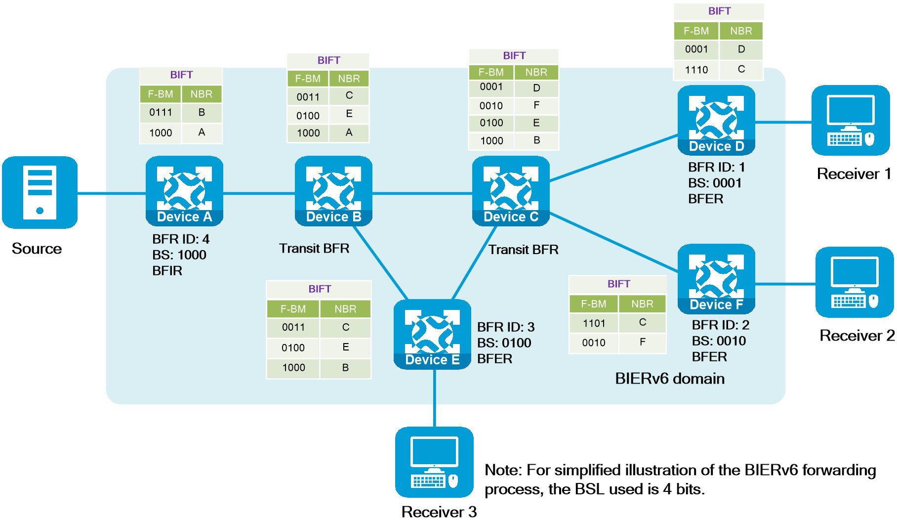
BIERv6 forwarding process
(1) A multicast packet arrives at the BFIR. The BFIR looks up the multicast forwarding table and finds that the egress interface for the packet is a BIERv6 tunnel interface. Based on this, it is determined that the packet needs to be forwarded using BIERv6, and the BFIR obtains required information for BIERv6 forwarding (BIFT ID and BS). BIERv6 forwarding information is generated through BGP MVPN routing interaction between the BFIR and BFER. As shown in the figure below, Device A learned via BGP MVPN routing that there are receivers downstream of Device D, Device E, and Device F. The BS value 0111 obtained is the result of performing a bitwise OR calculation on the bit positions corresponding to the BFR IDs of Device D, Device E, and Device F.
Figure133 BIERv6 forwarding process (1)

(2) BFIR performs "bitwise AND" calculations between the BS and F-BM in the BIFT one by one. If the resultant BS is not all zeros, a copy of the packet is encapsulated according to the BIERv6 packet encapsulation format and sent to the next-hop neighbor corresponding to that entry. The encapsulated BS value is the calculated value, the destination address is the next-hop neighbor's End.BIER SID, and the source address is the BIERv6 tunnel source address. As shown in the figure below, the BS value 0111 is ANDed with each F-BM in the BIFT on Device A. It is found that only the F-BM corresponding to Device B does not become 0 after the ANDing operation. Therefore, only one copy of the multicast packet will be duplicated and sent to Device B after BIERv6 encapsulation. The encapsulated BS value 0111 is obtained after the ANDing operation.
|
l As shown in the figure below, the F-BM corresponding to Device B in the BIFT on Device A is 0111, indicating that the BFR edge nodes that can be reached through the next-hop neighbor Device B on the optimal path are Device D, Device E, and Device F. The F-BM value 0111 is the bitwise OR calculation result of the bit positions corresponding to the BFR IDs of all BFR edge nodes that can be reached through Device B on the optimal path. l Multiple BIFTs exist on a BFR, and each BIFT for guiding BIERv6 forwarding is uniquely identified by the BIFT-ID in the BIERv6 packet. |
Figure134 BIERv6 forwarding process (2)
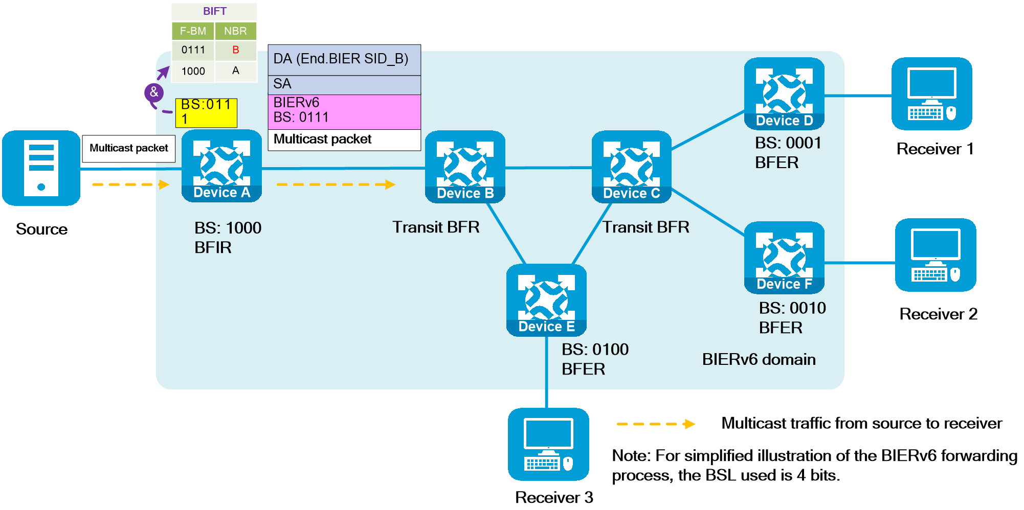
(3) A transit BFR will match the destination address of the header in the received BIERv6 packet with the locally configured End.BIER SID on the device.
· If a match is found, the transit BFR performs BIERv6 forwarding. The transit BFR performs the same operation as in step 2 and forwards the packet according to the BIFT to the next-hop neighbor. In the forwarding process, the source address encapsulated with BIERv6 remains unchanged. As shown in the figure below, the BS value 0111 is ANDed with each F-BM in the BIFT on Device B. It is found that only the F-BMs corresponding to Device C and Device E are not 0 after the ANDing operation. Therefore, one copy of the multicast packet will be duplicated and sent to Device C and Device E after BIERv6 encapsulation. The encapsulated BS value is 0011 for the packet sent to Device C. The encapsulated BS value is 0100 for the packet sent to Device E. The forwarding process on Device C is similar to Device B, and no further explanation is needed.
· If there is a match, regular IPv6 forwarding is performed..
|
l As shown in the following picture, the F-BM for Device C in the BIFT on Device B is 0011, which indicates that the BFR edge nodes that can be reached through the next-hop neighbor Device C on the optimal path are Device D and Device F. Although Device E can also be reached through Device C, this is not the optimal path. Therefore, the F-BM corresponding to Device C does not include Device E. l Similarly, the corresponding F-BMs for other BIFT entries are obtained according to the same rules. |
Figure135 BIERv6 forwarding process (3)
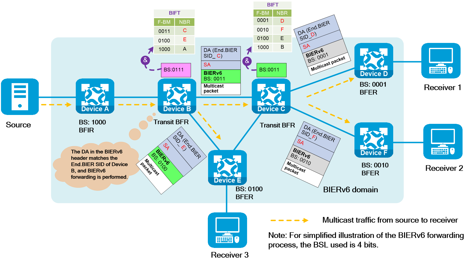
(4) The BFER needs to terminate BIERv6 forwarding after it receives a BIERv6 packet. The BFER first decapsulates the BIERv6 header to obtain the original multicast packet, then looks up the corresponding multicast forwarding table based on the Prefix-SID attribute in the SA, and forwards the multicast packet to the final multicast receiver according to the multicast forwarding table.
|
|
As shown in the figure below, taking Device D as an example, after bitwise AND calculations between BS value "0001" and each F-BM in the BIFT, it is found that the F-BM corresponding to the current node has a non-zero result after the bitwise AND calculation with the BS, indicating that Device D is a BFER and BIERv6 forwarding needs to be terminated on Device D. At this time, Device D sends the multicast packet to downstream multicast receivers after encapsulating the BIERv6 header and obtaining the multicast packet according to the multicast forwarding table. The operations on Device E and Device F are similar to those on Device D, and will not be repeated.
Figure136 BIERv6 forwarding process (4)
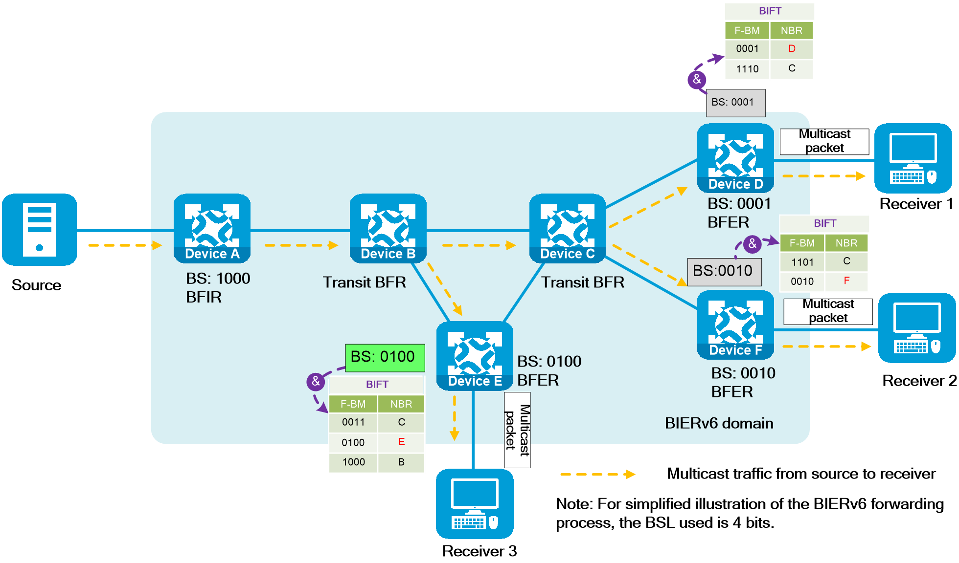
Typical applications
With the continued popularity of cloud networks, the number of devices connecting to the Internet has dramatically increased, and users' demands for network service quality have also been constantly raised. SRv6 technology and BIERv6 technology address the issues of how to efficiently and conveniently transmit data in unicast and multicast modes in IPv6 networks, respectively.
As shown in the figure below, deploy the BIERv6 feature in the core network of the service provider to transmit business data in multicast mode, and deploy the SRv6 feature to transmit business data in unicast mode. By combining SRv6 with BIERv6, it is possible to achieve a unified IPv6 data plane, unified IGP and BGP routing protocols, and provide users with complete unicast and multicast services, simplifying the protocols.
Figure137 BIERv6
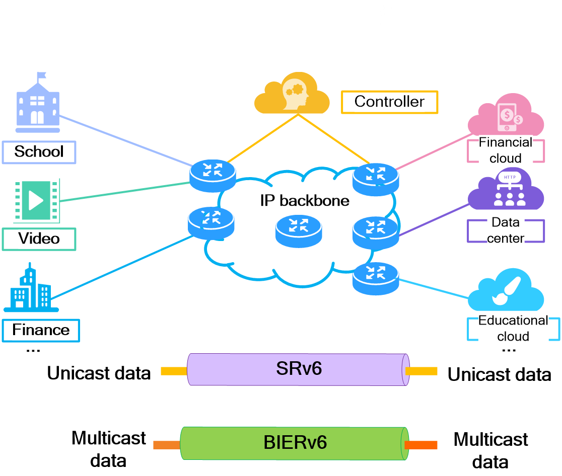
4.19 SRv6 SFC
About SRv6 SFC
SRv6 Service Function Chain (SFC) uses SRv6 TE policy to orchestrate the forwarding path for service packets. By adding the path information of an SRv6 TE policy in the original packet, the packet is guided to pass through each service node in the specified path sequentially. SRv6 SFC-supported service nodes include firewalls (FWs), intrusion prevention systems (IPS), load balancing (LB) devices, and network address translation (NAT) devices.
The SRv6 SFC technology meets the security and reliability requirements of different services in the network by flexibly controlling the service nodes through which the service packets pass.
SRv6 SFC is applicable only to the L3VPN over SRv6 TE policy scenario.
Concepts
Figure138 SRv6 SFC networking
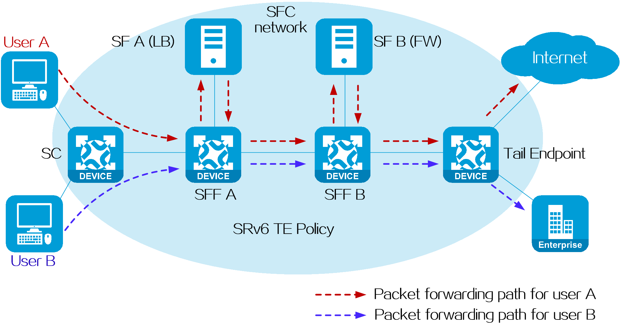
· SRv6 SFC network
An SRv6 SFC network is composed of SC, SFF, SF, and Tail Endpoint nodes. It is used to guide specific user service packets to designated service nodes for processing and forwarding to the destination.
· Service Classifier (SC)
Source node of the SRv6 service chain, which is located at the edge of the SRv6 SFC network. An SC creates SRv6 TE policies and steers service packets to SRv6 TE policies for forwarding.
· Service Function (SF)
Node that provides specific application services, such as firewall, load balancing, and address translation. An SF can be a physical device or a software product deployed on a virtual machine. An application service node that can recognize SRv6 packets is called SRv6-aware SF, and an application service node that cannot recognize SRv6 packets is called SRv6-unaware SF.
· Service Function Forwarder (SFF)
Node that acts as a service chain proxy for SFs. Based on the SRv6 SIDs of received packets, the SFF forwards the packets to the SFs associated with the SFF. The SFs process the packets, and then return the packets back to the SFF. The SFF determines whether to continue forwarding the packets.
· Tail Endpoint
Tail node of the SRv6 SFC network, which is the destination node (endpoint) of an SRv6 TE policy. The tail node forwards packets based on the SRv6 SID instruction.
· SFC operating modes
SRv6 SFC supports two operating modes: SRv6 service chain static proxy and SRv6 service chain masquerading proxy. The packet forwarding process is different for two operating modes.
SRv6 SFC static proxy
Scenario
The SRv6 service chain static proxy mode is applicable to scenarios where SFs cannot recognize SRv6 packets.
Fundamentals
Because the SFs cannot recognize SRv6 packets, the SFFs must decapsulate SRv6 packets and deliver the original packets from the user network to the SFs. After the SFs process the original packets, they forward the packets back to the SFFs. SFFs reencapsulate the packets with SRv6 headers based on the manually configured SID list, allowing the packets to continue forwarding in the SRv6 SFC network.
Operating mechanism
Configure QoS policies on the SC’s interface connecting to the user network and redirect specific user packets to designated SRv6 TE policies based on flow classification in the QoS policies.
In order to achieve service chain static proxy, it is necessary to create End.AS SIDs on the SFF and add the End.AS SIDs in the SID lists of SRv6 TE policies. An End.AS SID identifies an SF of the SRv6 service chain static proxy. The function of an End.AS SID is as follows:
· For packets delivered from an SFF to an SF, the SFF decapsulates the packets and then forwards the packets out of the interface associated with the End.AS SID.
· For packets delivered from an SF to an SFF, the SFF identifies the End.AS SID associated with the input interface (or input interface and inbound VLAN) of the packets, and then reencapsulates the packets, with the encapsulated SRH includes the SID list specified for that End.AS SID.
Figure139 SRv6 SFC static proxy operating mechanism
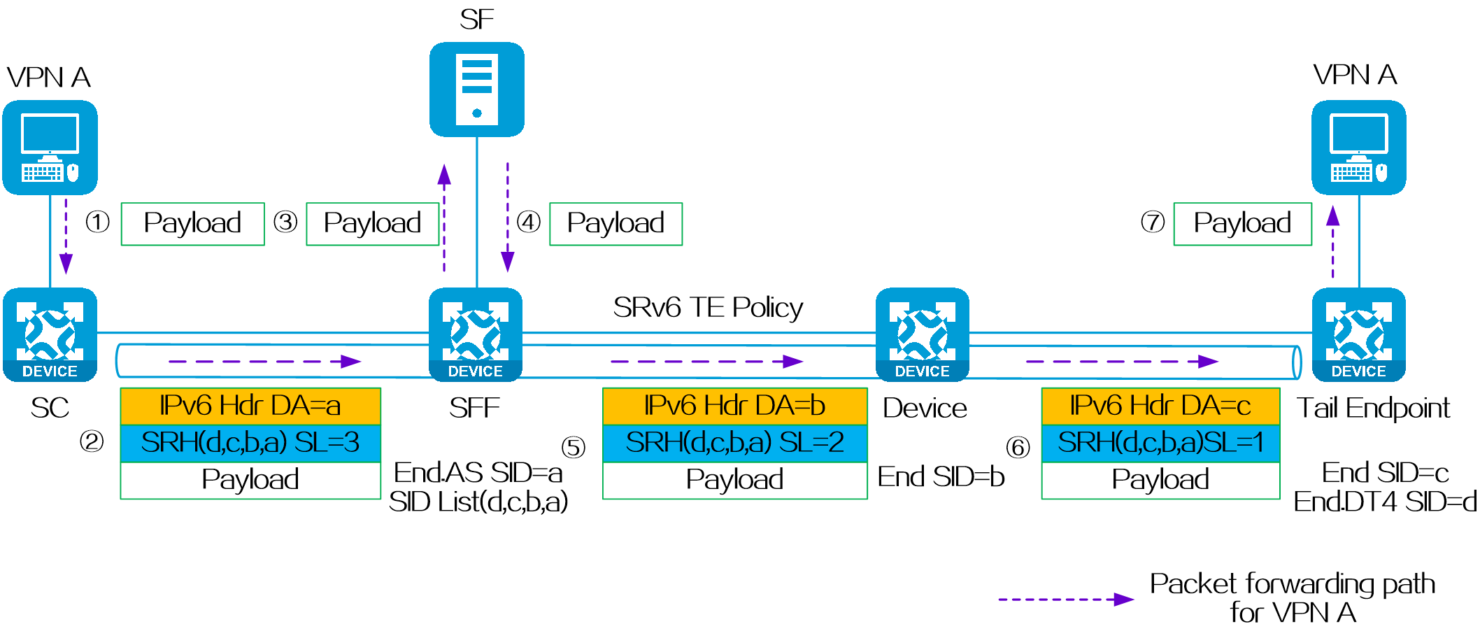
High availability for SRv6 service chains
When the SF is unreachable, the SFF discards the packets that should be forwarded to the SF. These packets cannot be forwarded in the SRv6 network or processed by subsequent SFs. In SRv6 SFC static proxy mode, the SFF supports dualhoming protection and bypass protection to improve the availability of the SRv6 SFC network.
· Dualhoming protection—An SF is dualhomed to two SFFs, one SFF is the primary SFF and the other is the backup SFF. When the primary SFF cannot reach the SF, it forwards service traffic to the backup SFF. Dualhoming protection is applicable to SFC networks where two SFFs connect to the same SF, and the configuration is relatively complex.
· Bypass protection—When an SF fails, packets can bypass the failed SF and reach the bypass SF for processing. Bypass protection is applicable to SFC networks where multiple redundant SF nodes exist.
|
|
Dualhoming protection
Figure140 SRv6 service chain with dualhoming protection in static proxy mode
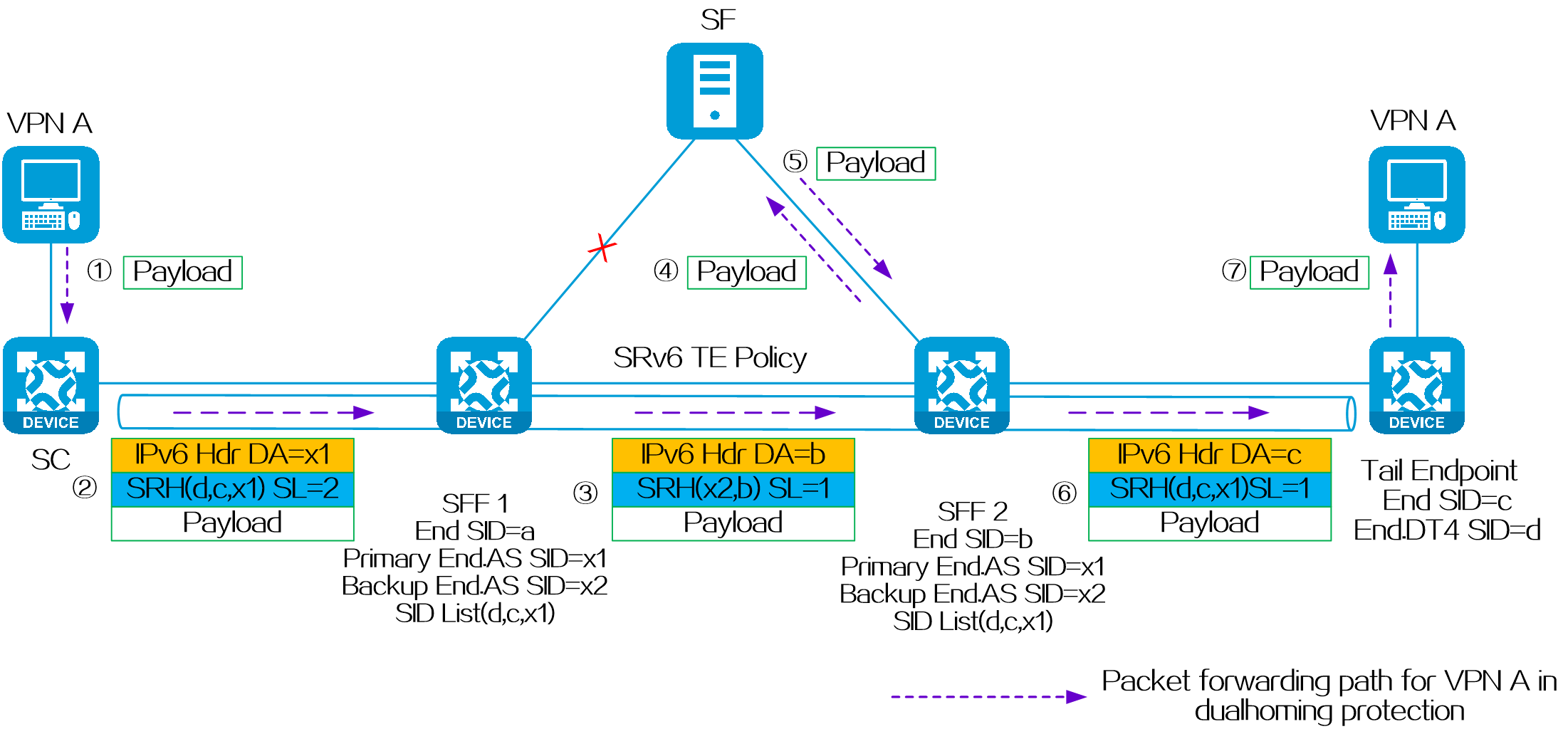
In dualhoming networking for static proxy mode, ensure the following configuration on the primary SFF (SFF 1) and backup SFF (SFF 2):
· Specify the End SID of one SFF as the backup peer SID of the other SFF.
· Configure the same primary and backup End.AS SIDs.
In the network shown in the above figure, when SFF 1 cannot reach the SF, SFF 1 removes the original IPv6 and SRH headers, and re-encapsulates the IPv6 and SRH headers. The new IPv6 header destination address is b, and the new SRH header contains the backup End.AS SID x2 and End SID b of SFF 2. Then, SFF 1 looks up the routing table based on the IPv6 destination address and forwards the packets to the backup node SFF 2. After the packets reach SFF 2, SFF 2 processes the packets according to the normal forwarding process of the SRv6 service chain static proxy.
Bypass protection
Figure141 SRv6 service chain with bypass protection in static proxy mode
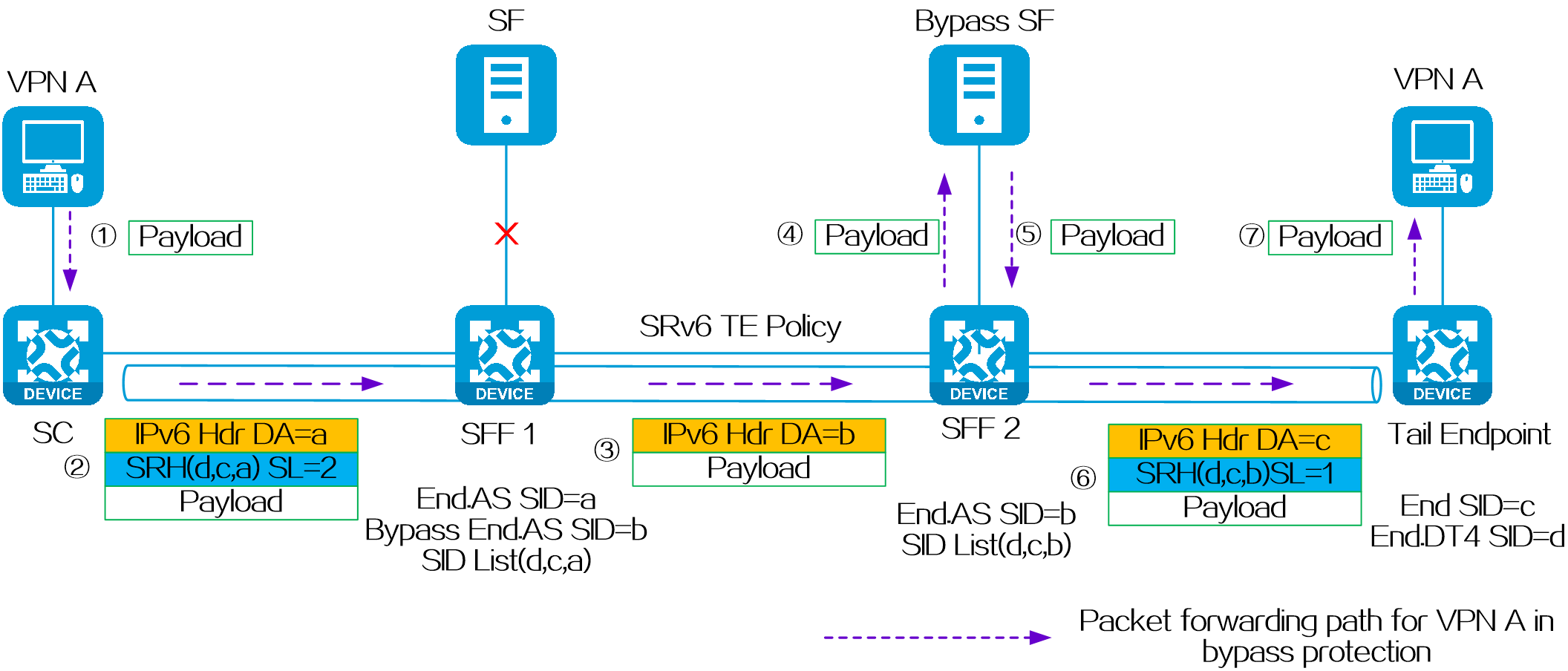
As shown in the figure above, to provide bypass protection for an SRv6 service chain in static proxy mode, enable the bypass protection feature on SFF 1. According to whether bypass End.AS SID is specified on SFF 1, the processing procedure of bypass protection varies.
· With a bypass End.AS SID specified on SFF 1:
¡ When SFF 1 cannot reach SF, SFF 1 removes the original IPv6 and SRH headers from the packets, and re-encapsulates an IPv6 header to the packets. In the IPv6 header, the destination address is the bypass End.AS SID (b).
¡ SFF 1 looks up the routing table to forward the packets to SFF 2.
¡ After the packets reach SFF 2, SFF 2 processes the packets according to the normal forwarding process of the SRv6 service chain static proxy.
· Without a bypass End.AS SID specified on SFF 1:
¡ SFF 1 skips the current End.AS SID (a) when it cannot reach SF 1, and changes the destination address of the IPv6 header to c.
¡ SFF 1 forwards the packets to the tail node according to the normal SRv6 forwarding process.
Both dualhoming and bypass protection
If both bypass protection and dualhoming protection are deployed in a network:
(1) When the primary SFF cannot reach the primary SF, packets are forwarded according to the dualhoming protection mechanism first. The primary SFF forwards the packets to the backup SFF, which then forwards the packets to the primary SF for processing.
(2) If the backup SFF cannot reach the primary SF either, the bypass protection mechanism is used. Packets are forwarded to the bypass SF for processing.
(3) When both dualhoming protection and bypass protection are unavailable, SFF will discard the packets.
Figure142 SRv6 service chain with dualhoming and bypass protection in static proxy mode
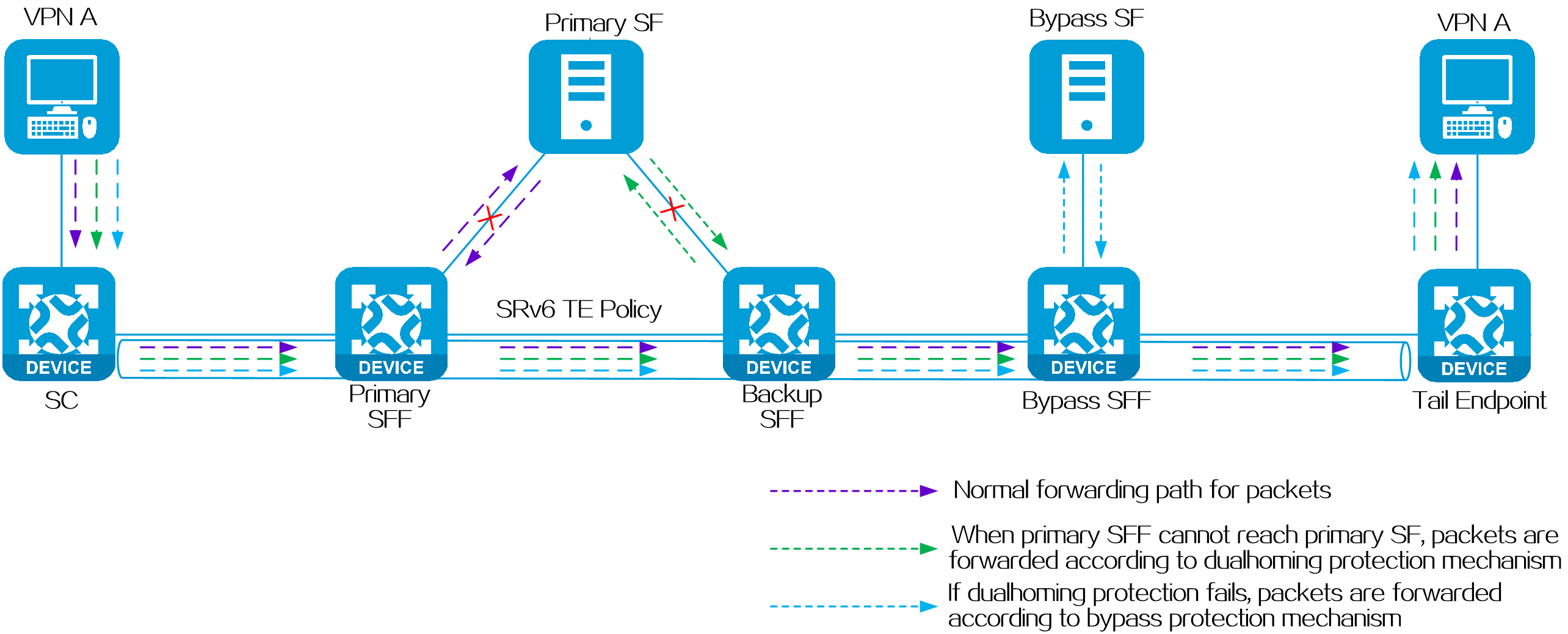
SRv6 SFC masquerading proxy
Scenario
The SRv6 service chain masquerading proxy mode is applicable to scenarios where SFs can recognize SRv6 packets.
Fundamentals
For packets delivered from an SFF to an SF, the SFF replaces the destination IP address of the SRv6 packets with SRH[0], which is the last SID value in the SID list of the SRv6 TE policy. Then, it forwards the packets out of the configured outgoing interface to the SF. The SF processes the packets and forwards the packet back to SFF without changing the source and destination addresses and SRH header information of the SRv6 packets. SFF then processes the packets according to the normal SRv6 forwarding process.
Operating mechanism
Configure QoS policies on the SC’s interface connecting to the user network and redirect specific user packets to designated SRv6 TE policies based on flow classification in the QoS policies.
In order to achieve service chain masquerading proxy, create End.AM SIDs on SFFs and add the End.AM SIDs in the SID lists of SRv6 TE policies. An End.AM SID identifies an SF of the SRv6 service chain masquerading proxy. The function of an End.AM SID is as follows:
· For packets delivered from an SFF to an SF, the SFF replaces the destination IP address of the SRv6 packets with SRH[0], and forwards the packets out of the interface associated with the End.AM SID.
· For packets delivered from an SF to an SFF, the SFF restores the destination address of the SRv6 packets to SRH[SL] and forwards the packets according to the standard SRv6 traffic forwarding process.
Figure143 SRv6 SFC masquerading proxy operating mechanism
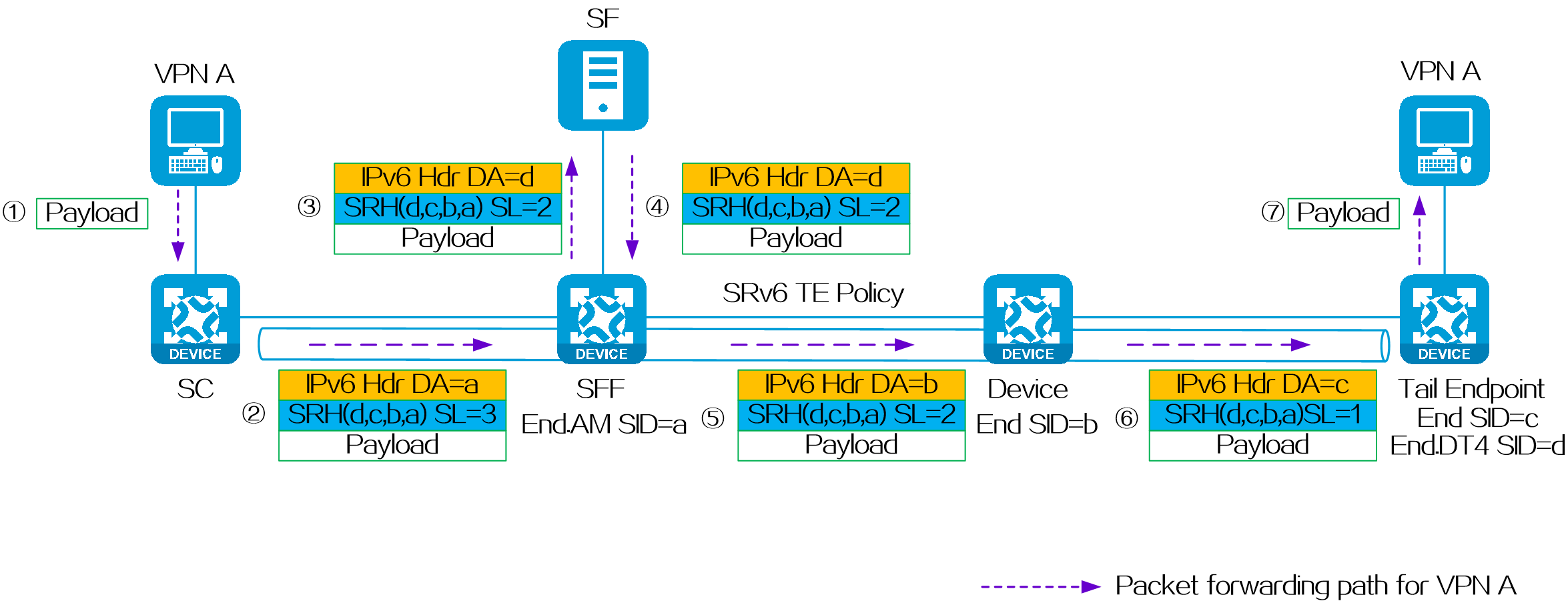
SRv6 SFC typical application
SRv6 SFC guides user packets destined for servers to the firewall to filter attack traffic and ensure network security.
Figure144 SRv6 SFC typical application
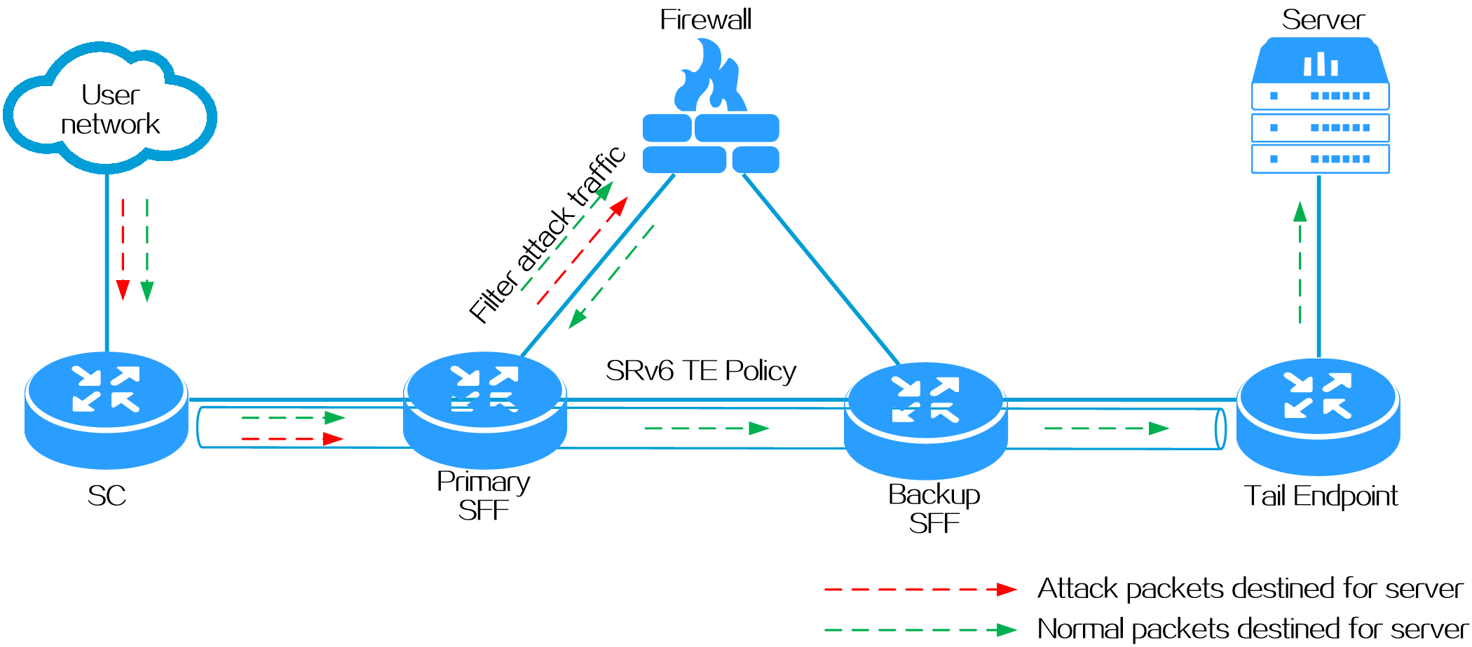
4.20 DetNet
About DetNet
Deterministic networking (DetNet) is a new network technology architecture built on Ethernet, providing end-to-end deterministic Quality of Service (QoS) guarantees for multiple services. The existing IP networks, with their best-effort forwarding logic and the presence of microbursts and congestion, cannot offer deterministic packet forwarding in the face of massive Internet connectivity. Based on IETF DetNet standards, H3C proposes an end-to-end deterministic data transmission solution using Resilient Cycle Queuing and Forwarding (RCQF). With the goal of promises made, promises kept, this solution can provide timely, stable, and reliable deterministic quality for large-scale network deployments.
DetNet employs various technologies and protocols to ensure low latency (timely), low jitter (stable), and low packet loss (reliable) for data transmitted over the network. This document will focus on the core technologies implemented on DetNet networks, including RCQF, Operations, Administration and Maintenance for Deterministic Networking (DetNet OAM), and multi-path transmission and forwarding technology.
· RCQF
RCQF is primarily used to meet the low jitter requirement in end-to-end deterministic transmission. It has been enhanced with flexible capabilities to adapt to WANs and 5G networks. The flexible capabilities of RCQF include adapting to transmission delay, transmission jitter, high bandwidth, large packet size, and interface speed.
· DetNet OAM
DetNet OAM is an active probing technique that achieves deterministic transmission of target packets on an SRv6 network. It constructs probing packets, measures the time slot deviation between neighboring nodes, and maps the packets to interface forwarding queues based on the time slot deviation. This ensures the deterministic transmission of service packets on an SRv6 network.
· Multi-path transmission and reception
The multi-path transmission and reception technology refers to duplicating packets into multiple copies on the ingress device and forwarding them through multiple paths. When the packets reach the egress device, they are selected and sent out as one copy. This technology ensures accurate delivery of packets to the destination even if a link failure occurs, while avoiding the time overhead of link switching.
Operating mechanism
Principles of RCQF-based end-to-end deterministic transmission
Figure145 Jitter principle
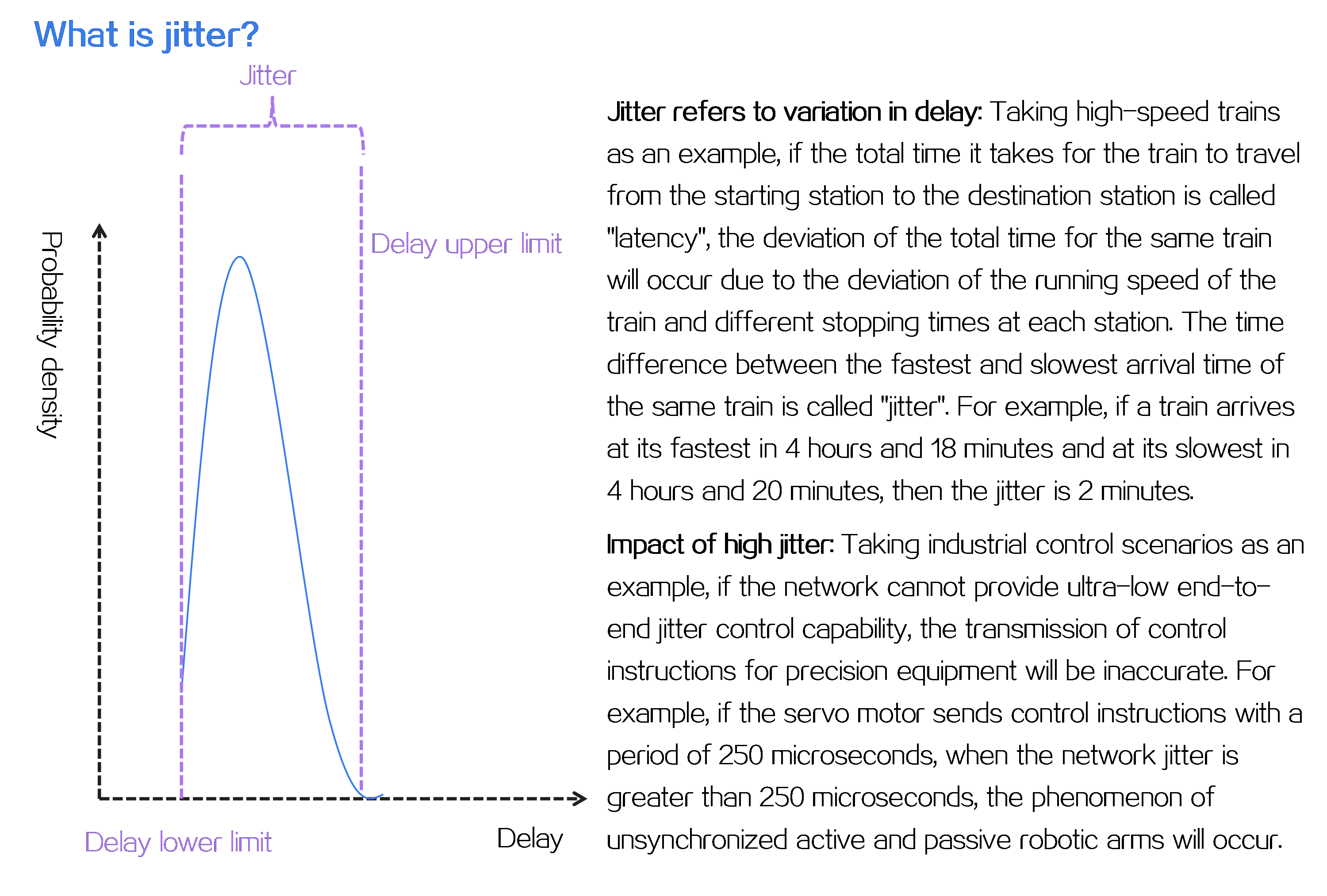
How does RCQF achieve low jitter?
RCQF employs a periodic queuing forwarding mechanism with the following basic ideas:
· In a DetNet, plan forwarding paths for each deterministic service flow.
· On deterministic forwarding devices, allocate a specific transmission period for each packet.
Figure146 Periodic queuing forwarding mechanism
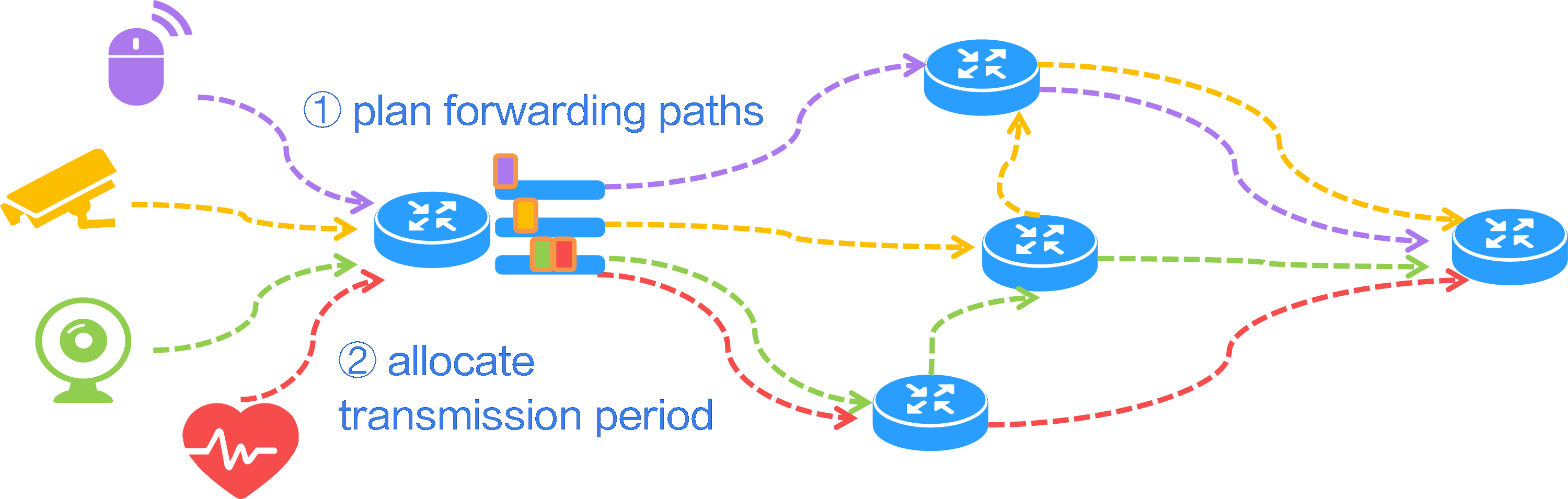
The basic mechanism for RCQF to achieve low jitter is as follows:
· Each forwarding node maintains frequency synchronization
(![]() ) and divides its time into equal time
periods (T).
) and divides its time into equal time
periods (T).
· The transmission timing of each packet on the
forwarding node is restricted to a specific period (![]() ).
).
· The jitter of each node is limited, ensuring that the end-to-end jitter is limited: 2 periods (Y-X=2T).
Figure147 RCQF-controlled lower jitter mechanism
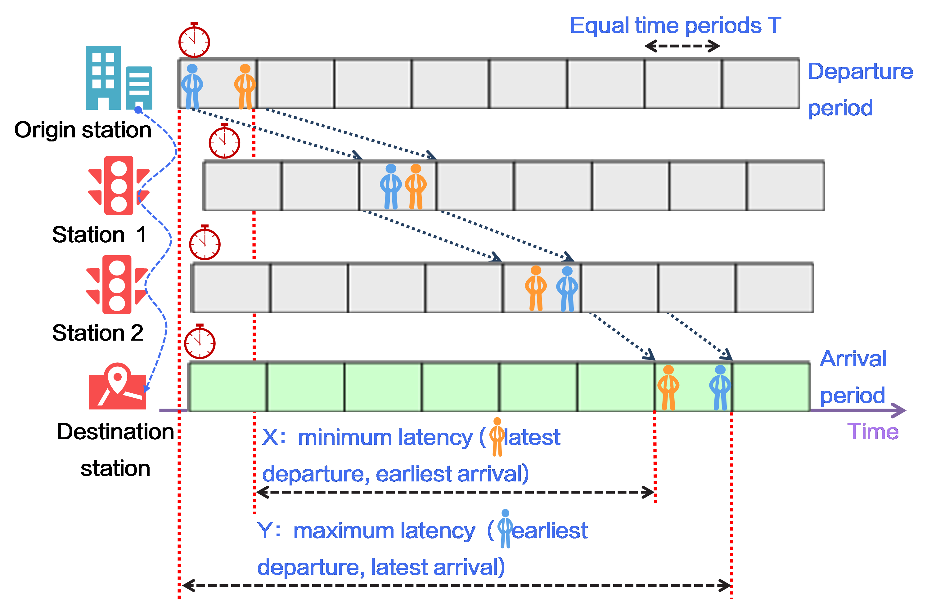
Basic principle of DetNet OAM for detecting inter-node time slot deviation
What is a time slot?
The device divides a memory block on the forwarding chip into 16 queues. Among them:
· Queues 1 to 15 are used for forwarding packets with deterministic transmission requirements.
· Queue 0 is used for forwarding packets that do not require deterministic transmission.
· Each queue forwards packets in a time piece (period or time slot) in a round-robin manner. Queue 1 corresponds to time slot T1, queue 2 to time slot T2, and so on, with queue 15 corresponding to time slot T15. The forwarding chip sequentially sends packets from queue 1 to queue 15, with each queue having a time duration of T.
· If the packets in a queue are all sent, but the corresponding time slot has not yet exhausts, the remaining time in the time slot is used to send non-deterministic packets from queue 0. Once the time slot expires, the next queue's deterministic packets are sent.
Figure148 Time slot deviation principle
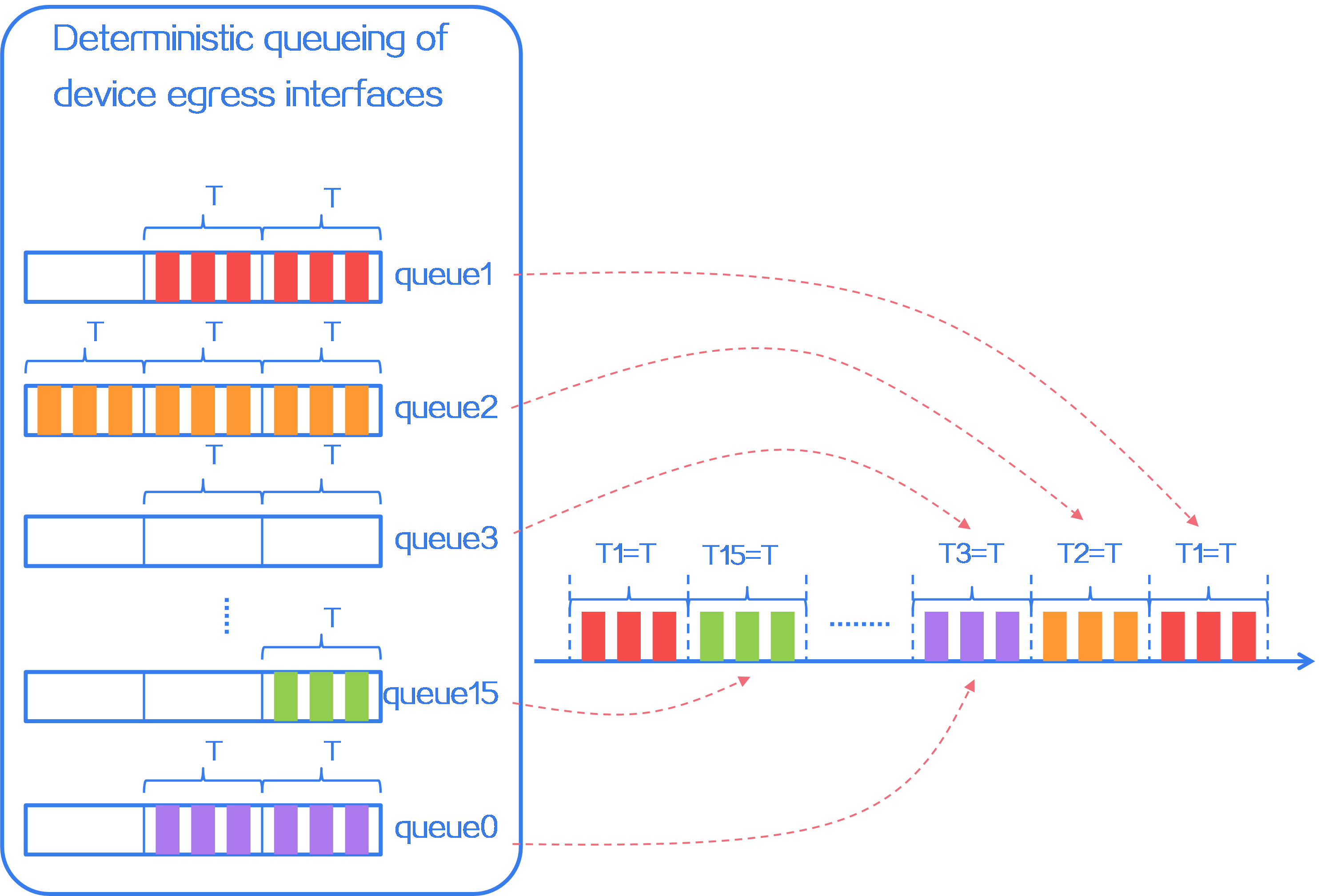
What is time slot deviation?
Time slot deviation refers to the deviation between time slots for sending packets between neighboring nodes. Since time slot numbers correspond to queue numbers, and each device clock is perfectly synchronized, the calculation method for time slot deviation is as follows:
· For the source node of SRv6, DetNet OAM time slot deviation = queue number that the DetNet OAM probe packet simulates leaving the device - queue number that the DetNet OAM probe packet enters the device.
· For the midpoint and endpoint nodes of SRv6, DetNet OAM time slot deviation = queue number that the DetNet OAM probe packet simulates leaving the device - queue number that the DetNet OAM probe packet simulates leaving the upstream device.
As shown in the following figure:
· Time slot deviation of source node A:Δta=Qa2-Qa1
· Time slot deviation of midpoint B: Δtb=Qb-Qa2
· Time slot deviation of endpoint B: Δtc=Qc-Qb
Figure149 What is time slot deviation?
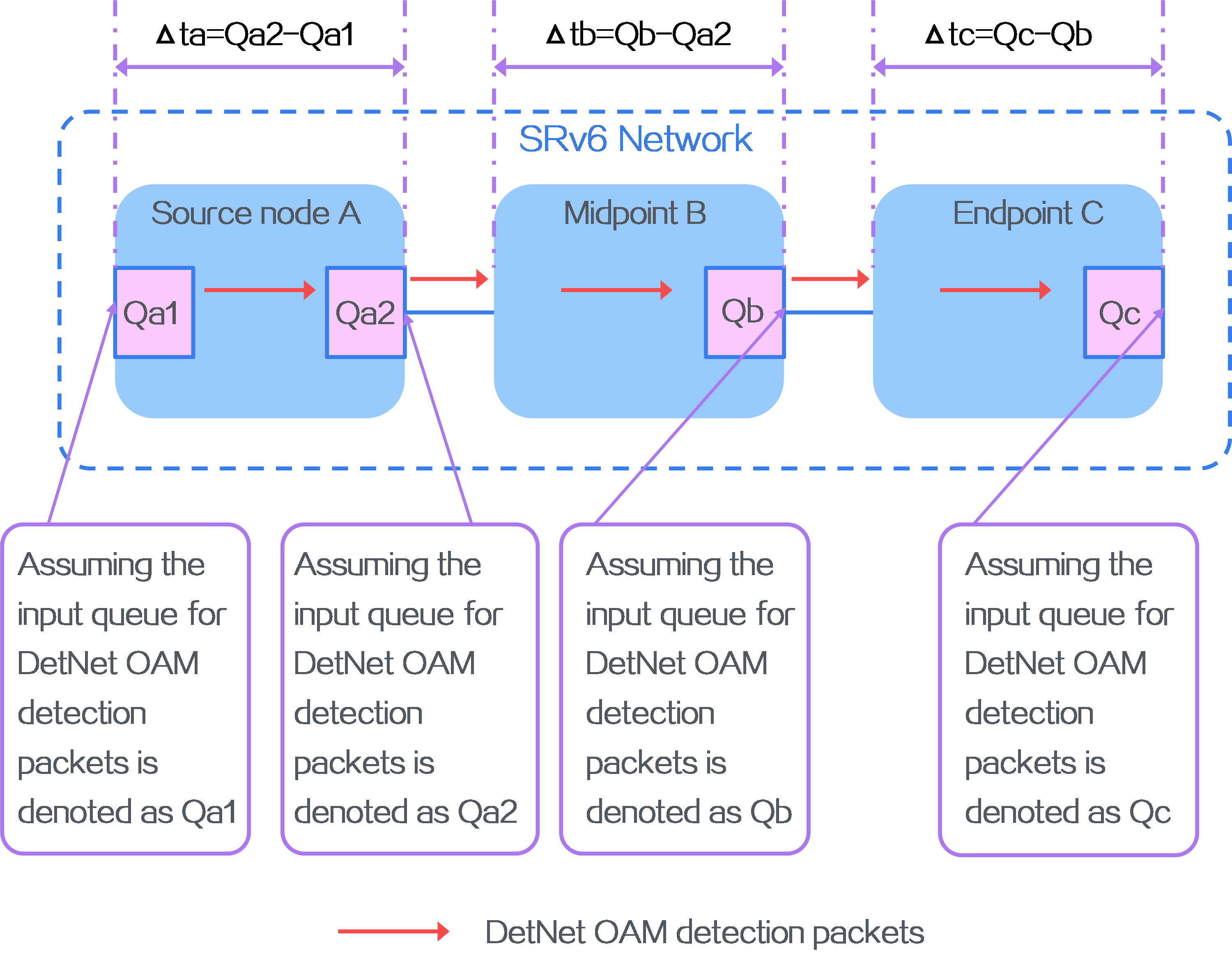
DetNet OAM mechanism
The core of DetNet OAM is to detect time slot deviation. Forwarding nodes map the time slot deviation to the egress queue of the service packet to guide packet forwarding. DetNet makes use of the maximum time slot deviation to guide forwarding and ultimately achieves deterministic delay jitter. The workflow for detecting the maximum time slot deviation between the DetNet OAM source nodes and neighboring nodes is as follows:
· The ingress node of the SRv6 path generates DetNet OAM probe packets by simulating service traffic, with 10 probes per period. The probe packets are forwarded along the segment list.
· The ingress node on the segment list detects the time slot deviation (Δt1) between the egress and ingress queues of its own probe packets. Other nodes calculate the time slot deviation (Δt2, Δt3, and Δt4) of probe packets between their egress queues and the corresponding upstream nodes' egress queues. The maximum, minimum, and average values of the time slot deviation from multiple probes within a period are sent to the controller.
· The controller takes the maximum value of the time slot deviation within the period and generates a time slot deviation list (Δt1, Δt2, Δt3, Δt4), which is sent to the ingress node.
· The ingress node encapsulates the time slot deviation list in the SRv6 header to guide packet forwarding.
Figure150 DetNet OAM mechanism
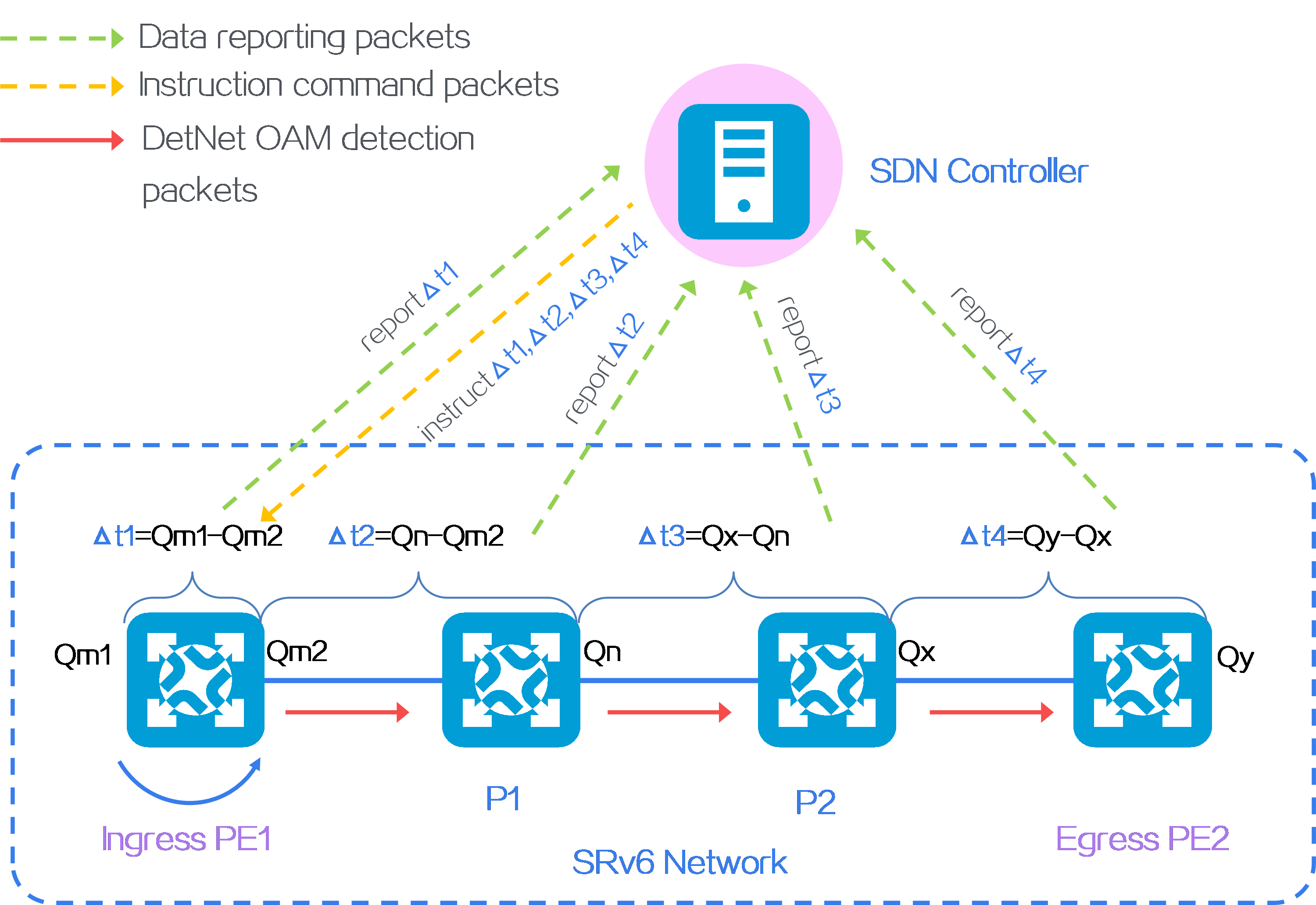
DetNet reliability from multi-path transmission and reception
What is multi-path transmission and reception?
In a DetNet, when multiple transmission paths exist, the first node replicates a deterministic service flow and sends it across these paths. At the destination node, redundant copies are eliminated and reordered to achieve backup. If a link fails, the deterministic service flow can still be forwarded from other paths to the receiver, ensuring no packet loss due to a single random event or device failure. This greatly enhances the reliability of the DetNet.
Figure151 Principle of multi-path transmission and reception
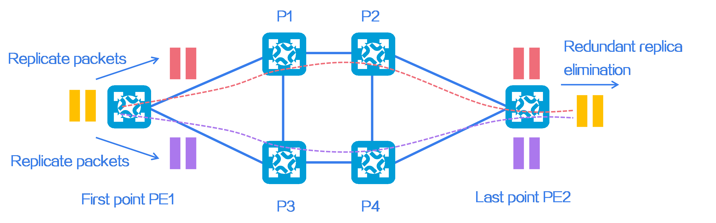
How to improve reliability through multi-path transmission and reception?
As shown in the following figure, the network has a certain failure rate. If multi-path transmission and reception is not used, packets are forwarded in the path of PE1 > P1 > P2 > PE2. Assuming each hop has a reliability of 0.99999, the overall reliability of this path would be 0.99999 * 0.99999 * 0.99999 ≈ 0.99997.
If multi-path transmission and reception is used, packets are simultaneously forwarded on the paths PE1 > P1 > P2 > PE2 and PE1 > P3 > P4 > PE2. As long as either path is normal, packets can be successfully delivered to the receiver. Therefore, the reliability of multi-path transmission and reception can be calculated as 1-[(1-0.99997) * (1-0.99997)] ≈ 0.999999999.
In summary, multi-path transmission and reception greatly enhances the reliability of the DetNet.
Figure152 Reliability through multi-path transmission and reception
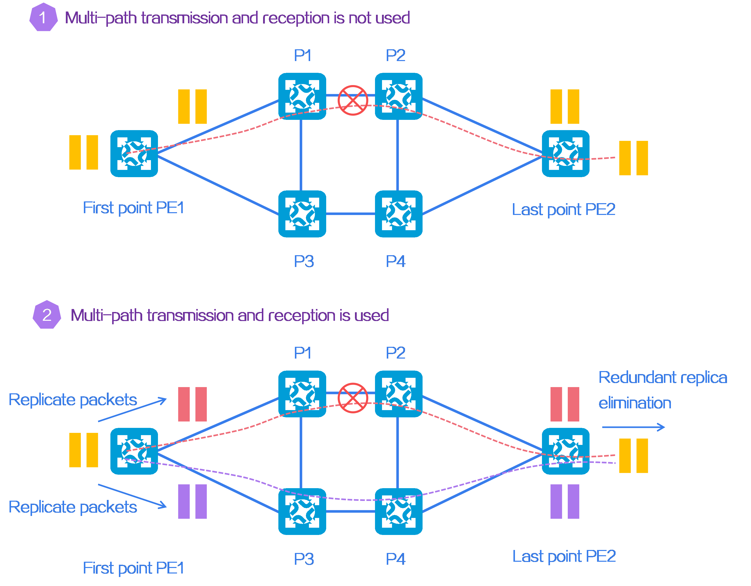
Application scenario
On the afternoon of February 23, 2022, the world's first DetNet was officially announced in Ji'nan, Shandong province, China. The province took the lead in building a high-quality DetNet that covers 16 backbone nodes with a total length of 5600 km.
The DetNet in Shandong province is constructed with the participation of H3C CR16000-F high-end routers. According to the test and evaluation conducted by China Academy of Information and Communications Technology (CAICT), this DetNet has its key performance indicators reaching an internationally leading level. Under the high load of 12G deterministic traffic + 80G background traffic, the average jitter of deterministic traffic was 6 us, and the maximum jitter was only 14 us. This has successfully achieved the research objective of end-to-end deterministic traffic jitter below 20 us for WANs.
4.21 APN6
About SRv6
Application-aware IPv6 Networking (APN6) is a new type of network architecture that uses IPv6 extension headers to carry application information. This allows network devices to identify applications and be aware of the application's requirements on the network, enabling granular and differentiated network services for different application services. APN6 couples the traditionally decoupled network and application layers in the TCP/IP protocol stack.
If an IPv6 packet is compared to a delivery package, the delivery note in the APN6 network not only includes sender and recipient addresses, but also carries the sender and recipient's VIP level (user groups in the network), package type (application service classification in the network), and customer's special requirements for logistics transportation time and process (latency and packet loss).
Figure153 APN6 network transmission information
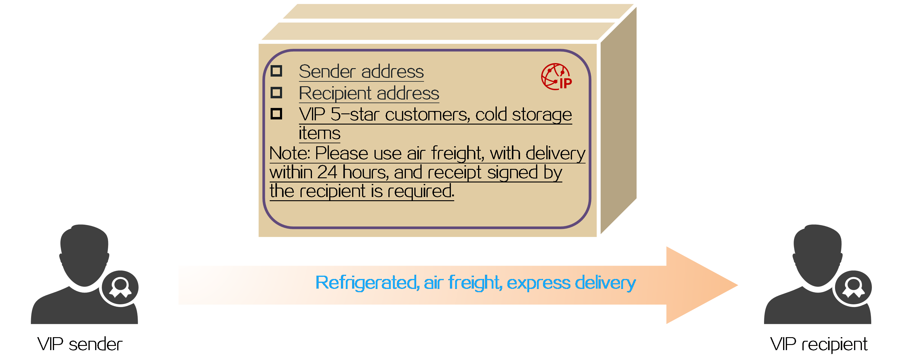
Basic concepts
APN6 packet and identification
As shown in the figure below, Comware uses Destination Option Header (DOH) to carry application information. The DOH might be in trace or E2E mode, depending on it location.
· Trace—The packet that carries application information can be analyzed and processed hop-by-hop by each forwarding device in the APN6 network. In this mode, the DOH is located before the SRH.
· E2E—The application information carried in the packet is only analyzed and processed during packet encapsulation and decapsulation. In this mode, the DOH is located after the SRH.
Figure154 Two modes for the DOH of an APN6 packet
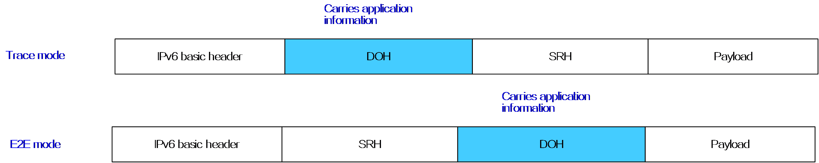
The application information carried in an APN6 packet in the APN6 network is called the APN header. The length of an APN header is variable and it contains the following information:
· APN ID—Identifier for the application, with a variable length. IPv6 packets in the APN6 network must carry an APN ID. APN IDs include APP-Group-ID and User-Group-ID.
¡ APP-Group-ID—Identifier for an application group, with a variable length.
¡ User-Group-ID—Identifier of the user group, with a variable length.
¡ Reserved—Reserved field.
· APN Parameters—Requirements of applications on network quality, for example, bandwidth, latency, jitter, and packet loss. This field is optional for IPv6 packets in the APN6 network.
Figure155 APN6 packet and identifiers
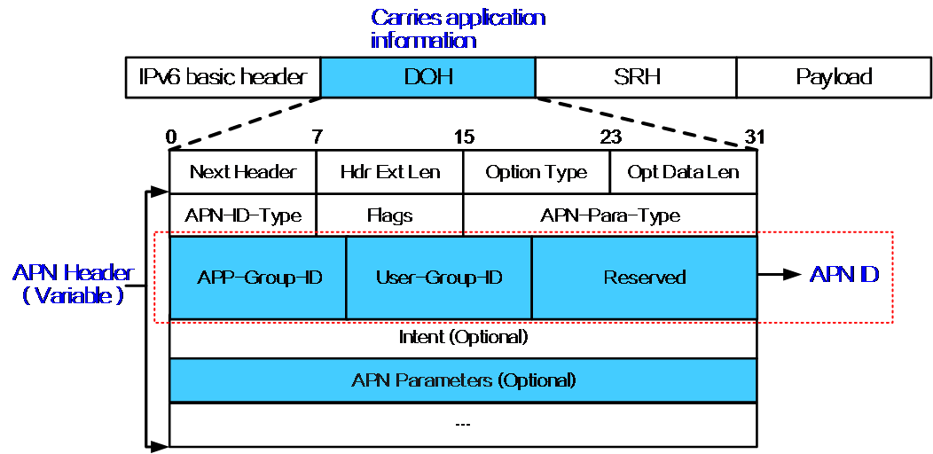
The IETF draft-peng-apn-yang defines the data model for APN ID, known as APN ID template. As shown in the following figure, assume that the APN ID is 64 bit long. When you configure the APN ID template, you can define the following information:
· Maximum length y that can be used by APP-Group-ID. You can also fill multiple field names in the APP-Group-ID field in index order, with each field name representing an application group.
· Maximum length x that can be used by User-Group-ID. You can also fill multiple field names in the User-Group-ID field in index order, with each field name representing an application group.
· The length of the reserved field is the total length of the APN ID minus x and y.
Figure156 Data model for APN IDs
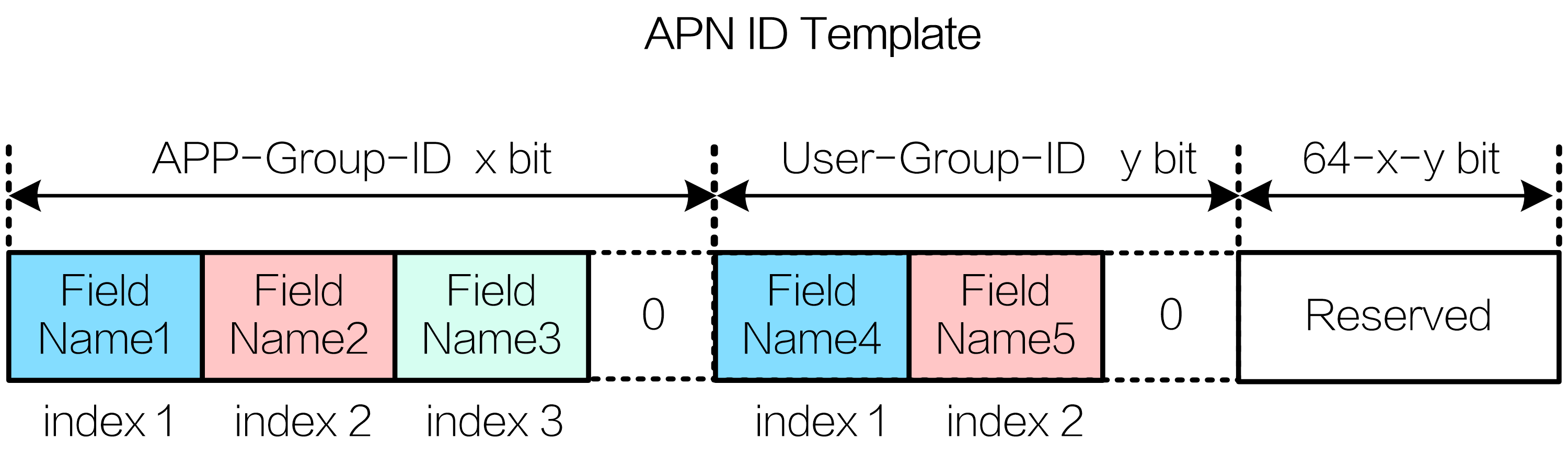
APN6 network architecture
An APN6 network contains the following roles:
· APN-Edge—APN6 edge device, which connects application terminals or application servers. An APN-Edge can mark the application information in APN6 packets based on QoS policies, such as the five-tuple of the packet, outer SVLAN, or inner C-VLAN.
· APN-Head—Head node of the tunnel. APN-Head can distribute traffic to the appropriate tunnel based on the application information in APN6 packets. An APN-Edge and the APN-Head can be the same device.
· APN-Midpoint—APN6 intermediate node, which can provide value-added services such as iFIT and SRv6 SFC based on application information carried in APN6 packets.
· APN-Endpoint—End node of the tunnel. It decapsulates APN6 packets. The APN-Endpoint can also forward IPv6 packets that carry application information.
· APN-Controller—Controller of the APN6 network. It plans and maintains APN ID and APN parameter information, defines and deploys forwarding and marking policies related to APN IDs.
Figure157 APN6 network architecture
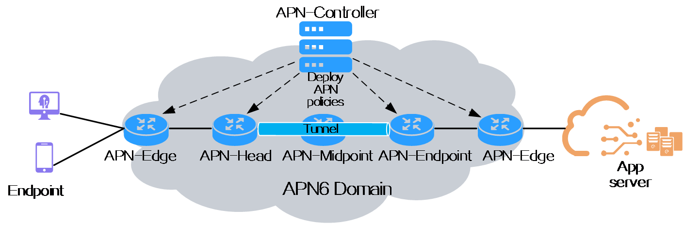
Benefits
Application information is simple and direct.
Traditional application packets do not contain requirements of applications on network quality and ACL rules are required to identify application packets. APN6 uses APN ID and APN Parameters to identify applications and users. In an APN6 network, only edge nodes carry APN ID and APN Parameters in the IPv6 packet header. Other intermediate devices in the network can identify application information by parsing the packet header, simplifying operations and deployment, and reducing hardware ACL resource consumption on each device.
Figure158 Comparison of packet identification by ACL and APN6
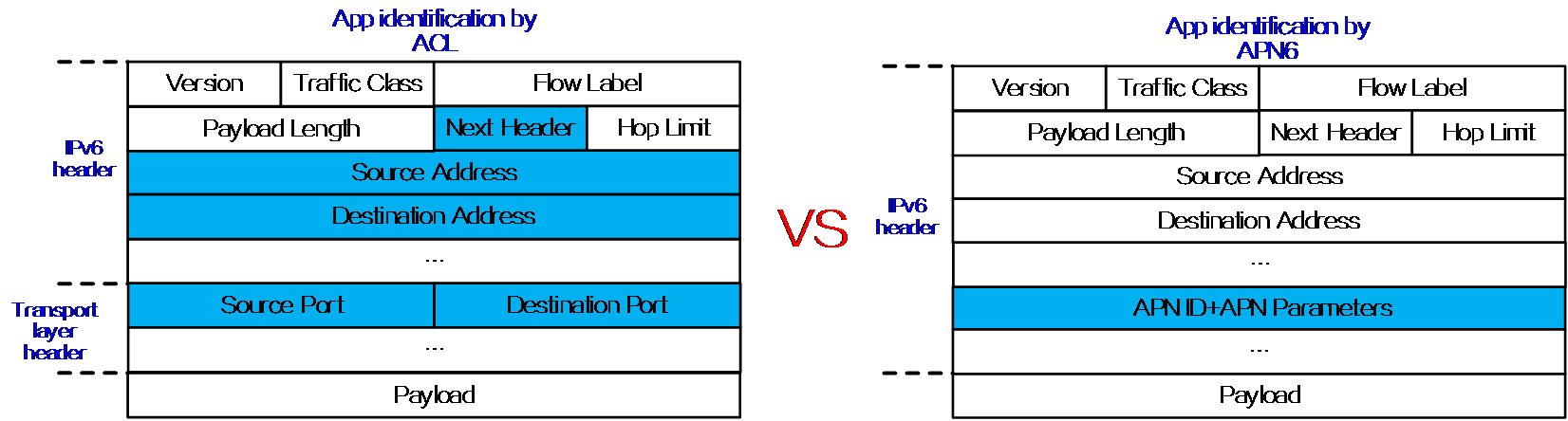
High scalability
An IPv6 extension header provides programmable space to carry rich APN6 application information for future extensions. Hop-by-Hop Options Header, DOH, and Segment Routing Header all provide programmable space and can be used to carry application information. Comware carries APN6 application information in the DOH according to the definition of draft-li-apn-ipv6-encap.
Figure159 All IPv6 packet headers can carry APN6 application information
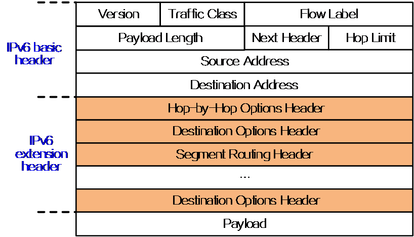
Good compatibility
APN6 is compatible with various IPv6+ technologies, such as SRv6 network slicing, deterministic networking, SRv6 SFC, and iFIT. With these technologies applied, an APN6 network can provide more granular network services. For example, with Srv6 network slicing applied, an APN6 network can provide dedicated slice networks for different applications, ensuring exclusive resource allocation. With iFIT applied, it can provide application-level performance policies, fault identification, and visualized Ops in real time.
Figure160 Compatibility with various IPv6+ technologies
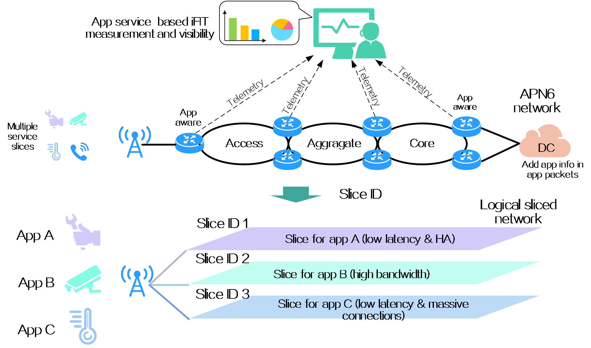
Applications and value
As shown in the following figure, on an SDWAN network where branches are connected to the data center, you can deploy APN6 to provide the following features:
· Path selection—Based on the APN ID, user A's specific traffic is distributed to the corresponding SRv6 TE Policy tunnel for forwarding. The traffic is then routed from the client to the backbone network and to the cloud data center, achieving end-to-end unified path planning. SRv6 TE Policy ensures availability for specific traffic.
· Isolation policy—On PE A, you can configure an isolation policy based on APN IDs to prevent users identified by the APN IDs from accessing the data center, implementing flexible access control.
· Fault detection—For some Esports competition traffic and important video conference services, you can deploy iFIT to achieve hop-by-hop service quality monitoring and fault location for specific application traffic. Once a network segment has flappings, faults can be quickly identified and optimizations can be performed.
Figure161 APN6 application
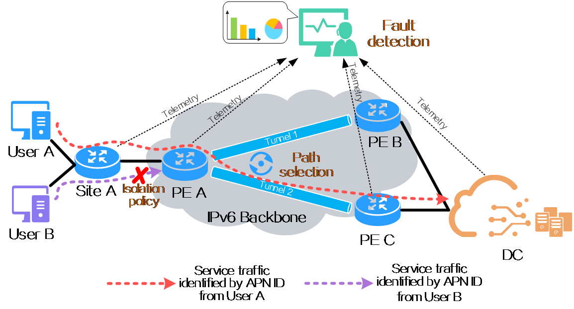
5 Recommended solutions
5.1 IPv6+ carrier cloud-network convergence solution
Pain points of customers
The application and development of Network Function Virtualization (NFV) technology has freed network carriers from dependency on dedicated hardware. By deploying NFV and cloud network elements in data centers, carriers can provide enterprise customers with diverse and custom value-added services. Therefore, carriers have been actively deploying cloud data centers (CDCs). The convergence of CDC and traditional networks (including MAN, IP bearer network, and IP backbone network) has been a major trend among the current networking schemes.
During deployment of the cloud-network convergence solution, network carriers face the following challenges:
· When SRv6 is used to carry services, SRv6 packet headers cost too much, resulting in low bandwidth resource usage. In scenarios where SRv6 SFC service chains are deployed or TI-LFA FRR is triggered, SRv6 packets might be larger than MTUs.
· Since visualized O&M is not supported, customers are unable to clearly locate faults (on the network side or cloud data center side).
Figure162 Drawbacks of traditional O&M solutions
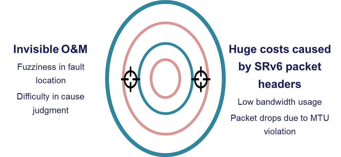
Solution introduction
H3C has proposed a cloud-network convergence solution that supports G-SRv6 and iFIT-based measurement to meet the requirements of network carriers on enterprise cloud services.
Solution benefits
H3C's cloud-network convergence solution adopts the G-SRv6 and iFIT technologies to remove the pain points of customers as follows:
· The controller manages access networks, MANs, and core devices of the solution in a centralized manner. The controller's northbound interface provides users with business orchestration capabilities, enabling agile deployment and automated opening to achieve rapid service deployment.
· In this solution, all core devices use EVPN L3VPN over SRv6 to carry services, and are deployed with G-SRv6 to compress SRH extension headers and thus reduce additional costs. This improves the effective payload and bandwidth usage of the entire SRv6 network.
· Hop-by-hop iFIT-based measurement is configured on cloud PEs and network PEs. By subscribing to iFIT measurement information through Telemetry, the controller can visualize quality data of the network between cloud PEs and network PEs. This makes real-time tunnel adjustment possible in the network section and enables fast location of faults.
Figure163 Benefits of the cloud-network convergence solution

Solution networking
CR19000 series core routers act as cores in the cloud-network convergence solution. They are deployed with EVPN L3VPN over SRv6 to carry services, and use technologies such as G-SRv6 and iFIT to meet user requirements.
· Administrators can orchestrate traffic forwarding paths and the required value-added features through the unified portal.
· The controller obtains the configurations made by administrators from its northbound interface, and then delivers those configurations information to MANs and the core devices in cloud networks through NETCONF.
· The controller subscribes to iFIT measurement information through Telemetry, analyzes quality of the network between cloud PEs and network PEs, and visualizes the network quality information.
Figure164 Network diagram
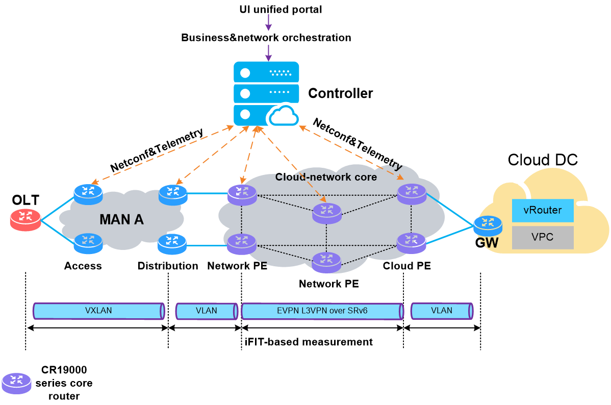
5.2 IPv6+ carrier cloud IPTV solution
Pain points of customers
The multicast technology is crucial to IPTV. The channel signal source is equivalent to multicast source, the endpoint user is equivalent to multicast data receiver, and the channel corresponds to multicast group.
Figure165 Operating mechanism of the traditional multicast technology
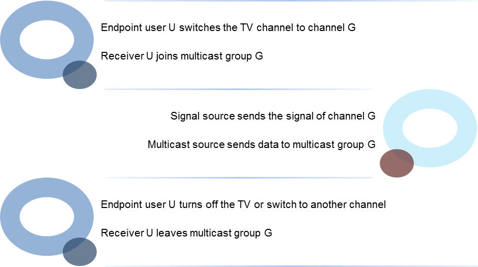
When the IPTV system uses the traditional multicast solution, the following issues exist:
· Intermediate network nodes participate in operation of the multicast protocol and maintenance of multicast entries, which leads to high O&M costs and challenges such as difficulty in business scaling and lack of business flexibility.
· With the large-scale deployment of multicast services, multicast table convergence tends to be very slow whenever there is a network change. For example, when new users join multicast groups, multicast table convergence always takes a long time, causing poor user experience.
Figure166 Bottlenecks of the traditional multicast solution
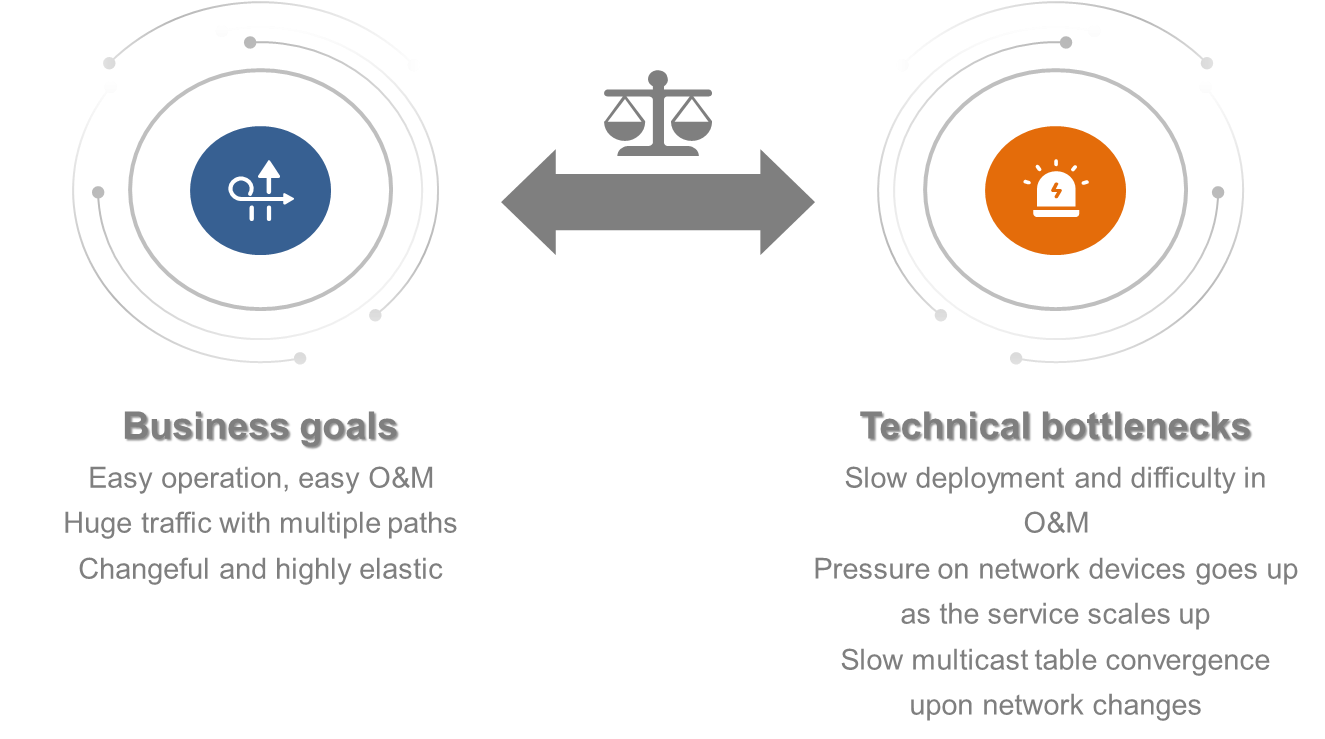
Solution introduction
H3C provides a G-BIER-based multicast solution to meet the increasingly growing demand for multicast services and adapt to the development trend of network architecture.
This solution supports multicast source deployment in the cloud and rapid deployment of multicast services. Multicast sources are transparent to users. This solution also facilitates user participation in multicast groups, better adapting to the trends of cloud-based services among network carriers.
Solution benefits
Driven by G-BIER, the new multicast solution optimizes multicast networks to reduce the pain points of customers as follows:
· Multicast service deployment does not involve intermediate network nodes, simplifying operations and accelerating service deployment.
· Multicast service changes do not affect network intermediate nodes, eliminating network pressure brought by large-scale multicast service deployment and thus enhancing multicast service scalability.
· Intermediate nodes in the network do not need to be aware of multicast services. When users join or leave the multicast group, multicast table convergence is completed fast, reducing the wait time of endpoint users.
· Intermediate nodes in the network do not need run the PIM protocol, simplifying O&M operations and saving O&M costs.
Figure167 Benefits of the G-BIER-based multicast solution
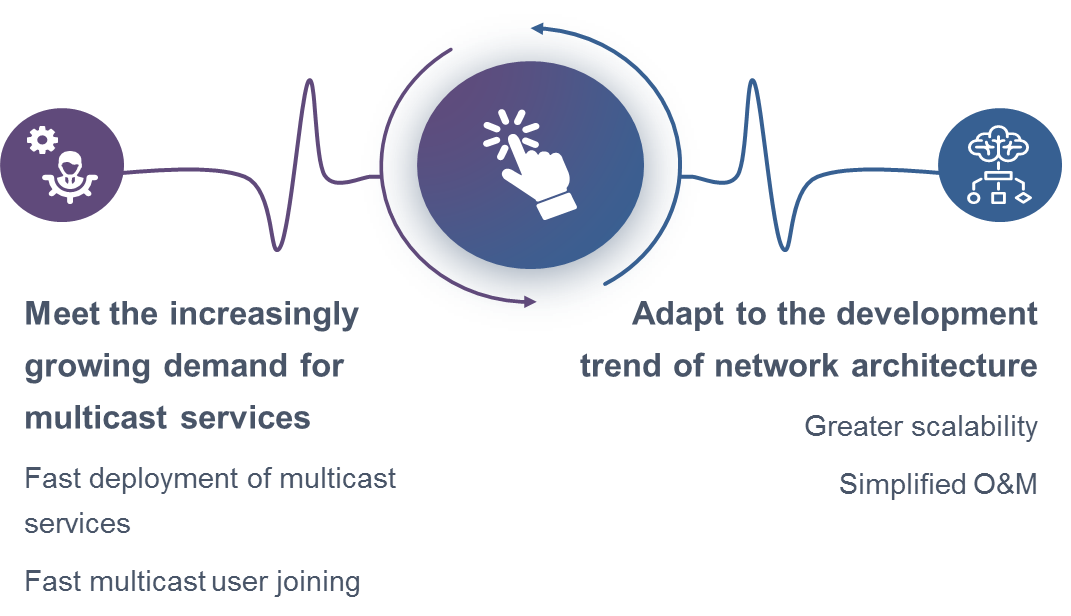
Solution networking
To ensure service HA, the solution uses the dual-root hot backup mode. The cloud multicast source is connected to the primary and backup root nodes through the Ethernet switch SW. With the help of G-BIER, core devices and BRASs, the multicast source provides IPTV services to homes or enterprises.
Figure168 Network diagram
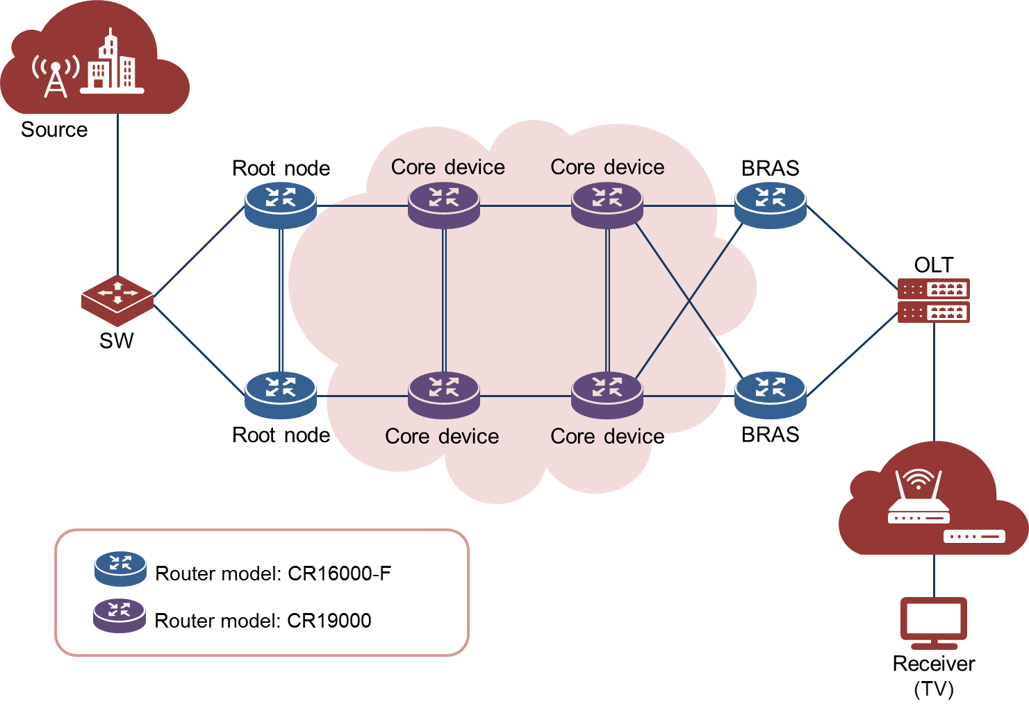
5.3 IPv6+ e-government extranet solution
Pain points of customers
E-government extranet involves outbound information transmission and interconnection. Related customers have the following requirements:
· IPv6: The e-government extranet needs to promote large-scale deployment and application of Internet Protocol version 6 (IPv6).
· High bandwidth: Customers require sufficient bandwidth resources to support large-scale data transmission and high-load e-government applications, ensuring timely transmission and processing of government information.
· High availability: To ensure that the e-government system runs correctly and has high reliability and stability, the e-government extranet must run stably and continuously (round-the-clock operation) and possesses fault tolerance and disaster recovery capabilities.
· High integration: The e-government system is very complex, consisting of information systems from multiple departments. Customers hope that the e-government extranet can achieve unity and integration of government systems, providing one-stop services.
· Efficient O&M: Customers want to simplify O&M processes and operations by introducing automated and intelligent O&M management tools. They also require capabilities of real-time monitoring and fast fault locating to achieve cost-effective O&M of the e-government extranet.
Solution introduction
H3C has proposed a new-generation IPv6+ e-government extranet solution that uses new technologies such as SRv6, network slicing, and iFIT.
Solution benefits
· Upgrade to IPv6 network: This solution helps reconstruct the e-government public platform to IPv6, providing sufficient IP addresses in multiple business scenarios such as data centralization, smart city governance, and mobile office.
· Ultra-bandwidth: This solution provides a 40G/100G backbone network to carry services such as government businesses and market regulation for all government departments within a province.
· Reliable architecture: The network architecture consists of two network planes built by different carriers to achieve remote disaster recovery. When the primary plane fails, the secondary plane can quickly take over to ensure network continuity and high availability.
· Ubiquitous access: This solution supports the access of 5G government businesses, Internet of Things (IoT), as well as unified access of public organizations such as schools and hospitals.
· Efficient O&M: This solution uses iFIT to achieve rapid fault identification and location, promoting O&M efficiency and thus improving the satisfaction of government customers.
Figure169 Benefits of the new-generation IPv6+ e-government extranet solution
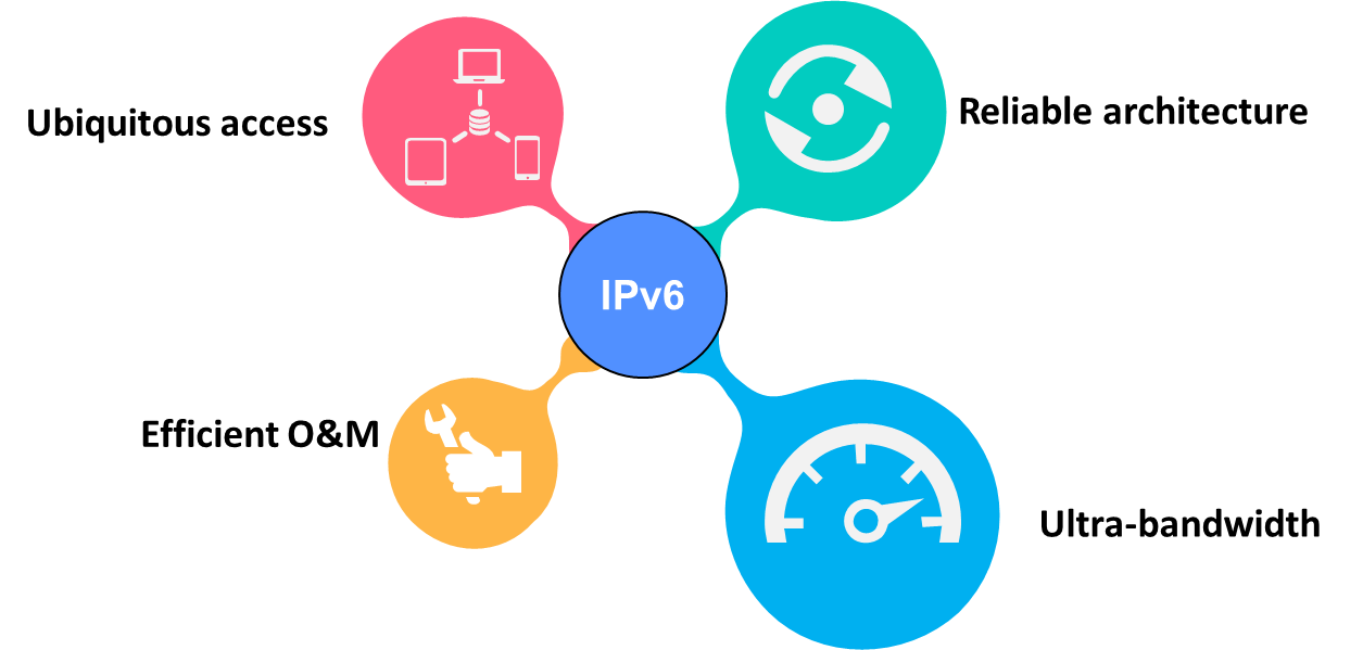
Solution networking
Driven by the IPv6+ technology, this solution optimizes the e-government extranet to reduce the pain points of customers as follows:
· Ultra-bandwidth network architecture: This solution builds a 40G/100G ultra-bindwidth e-government extranet with routers.
· Primary and secondary network planes: The network architecture contains two planes built by different carriers for high availability purposes. The two planes back up each other.
· Network slicing: Network resources are divided into multiple independent and manageable network segments according to different business logics, achieving unified carrying of different businesses, bandwidth/delay guarantee for specific businesses, and exclusive resources for critical businesses.
· IPv6+ technology: This solution uses the SDN architecture and the SRv6 technology to carry EVPN L3VPN and IPv4/IPv6 services in a unified manner, providing differentiated guarantees for traffic engineering and network SLA. This ensures overall network reliability and efficiency. The SDN controller subscribes to iFIT measurement information through Telemetry to visualize service quality information, enabling network administrators to perform real-time network performance monitoring and optimization.
Figure170 Network diagram
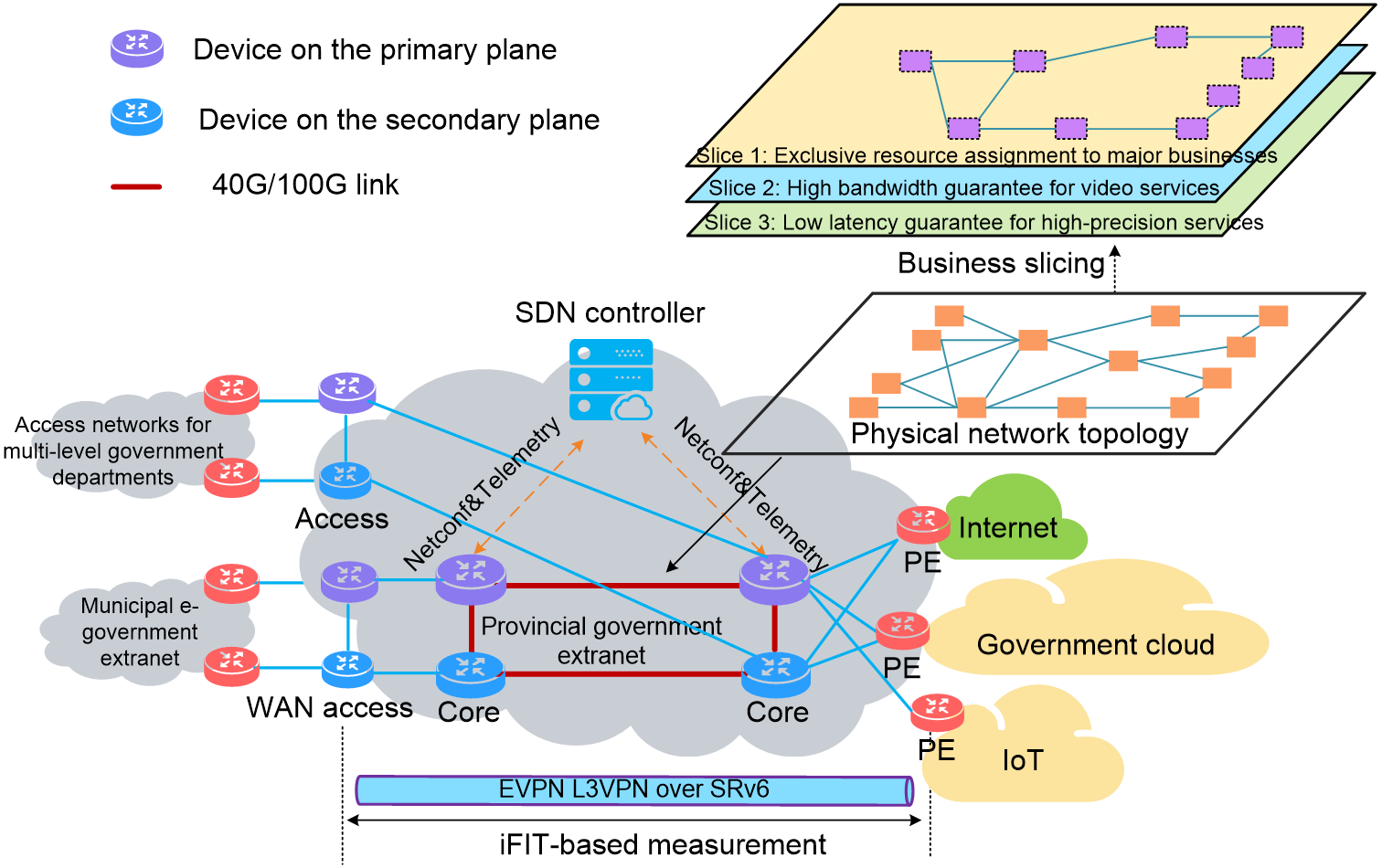
5.4 IPv6+ power backbone network solution
Pain points of customers
As power production and data network keeps developing and upgrading in the intelligent power sector, users need to pay attention to key services such as power system monitoring, oil and gas pipeline monitoring, and monitoring of oil and gas refining processes. Deploying these services in traditional IP networks will pose the following challenges:
· Business resource isolation: To reduce construction and O&M costs, enterprises hope to isolate different business resources in a single network to achieve exclusive resource assignment. In traditional IP networks, services obtain resources in preemptive mode, which prevents exclusive resource assignment.
· Low jitter: In traditional IP networks, a traffic burst might result in unstable packet forwarding latency. Ultra-reliable low-latency communication (uRLLC) services have high requirements on jitter and deterministic networking. The requirement on jitter varies by uRLLC service. Traditional IP networks cannot meet the different jitter requirements of uRLLC services.
· Ultra-high reliability: For uRLLC services, customers require a reliability level of 99.9999%, which cannot be met by traditional IP networks.
· Fine-grained business management: In traditional IP networks, if a service traffic change occurs suddenly, it will affect other services. To address the issue, fine-grained business management is required.
Figure171 Challenges faced by traditional IP networks
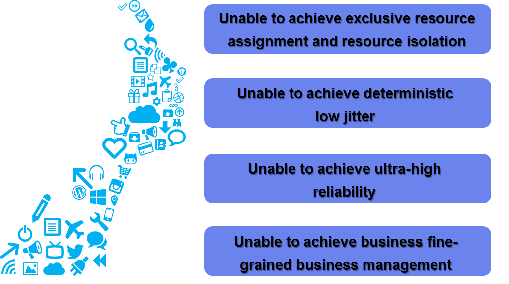
Solution introduction
H3C's intelligent power solution adopts the network slicing and deterministic networking technologies to better accommodate diverse services in the intelligent power network and ensure deterministic jitters.
Solution benefits
H3C's intelligent power solution ensures the reliability of uRLLC services by reducing the downtime upon faults. It addresses the pain points of customers and brings practical benefits and values to customers.
· Fine-grained network slicing: The entire network is deployed with SDN/SRv6, and the controller performs automated and fine-grained network slicing for businesses. The controllers isolates business connections and access and assigns exclusive network resources to different network slices in the network. This prevents businesses from affecting each other in the network. Customers can meet different SLA requirements in one network.
· Differentiated SLA guarantee: Different network slices provide differentiated SLA guarantees based on network bandwidth, latency, jitter, and other SLA requirements, to satisfy various services. All types of businesses can receive service guarantees that meet their needs, thus improving customer satisfaction.
· High reliability: SRv6-based network slicing has high reliability, because it supports multiple reliability mechanisms (such as TI-LFA). This technology provides protection for failure points in IP networks and effectively reduces the downtime of customers upon failures, enhancing service continuity and stability.
· Deterministic jitter: Deterministic networking provides deterministic forwarding capabilities with bounded latency and bounded jitter. uRLLC services is highly reliable with microsecond-level jitter, improving the services of customers and their competitive advantages.
Figure172 Benefits of network slicing and deterministic networking
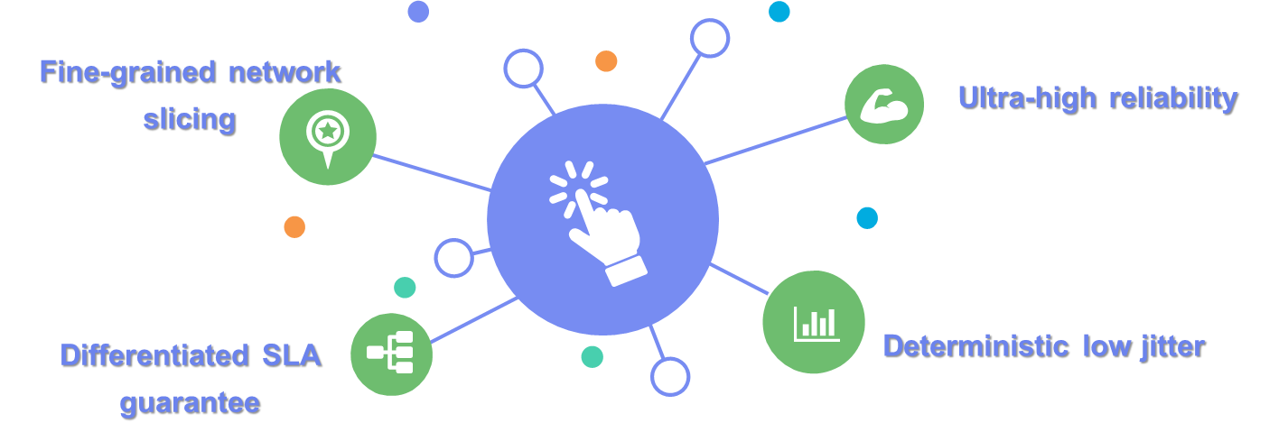
Solution networking
Provincial backbone networks use CR19000 series core routers and municipal access networks use CR16000-F series high-end routers. The entire network is deployed with EVPN L3VPN over SRv6 to carry business and adopts technologies such as network slicing and deterministic networking to meet user needs.
· The controller performs fine-grained network slicing for different businesses based on their SLA requirements.
· Deterministic networks are deployed for each network slice based on the jitter requirements of related business, such as uRLLC services.
Figure173 Network diagram
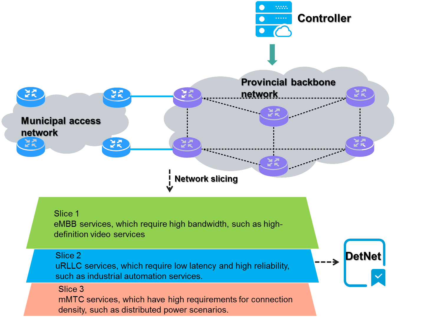
5.5 IPv6 + education backbone network solution
Pain points of customers
Smart education is a new educational model that combines informationization with education through Internet technologies, providing teachers and students with more intelligent teaching and learning experiences, services, and support.
Although smart education is widely applied, existing smart education networks suffer from insufficient network bandwidth, slow network transmission speed, high network latency, significant network security risks, and poor flexibility and scalability. The IPv6+ smart education solution can use technologies such as SRv6, iFIT, and SAVNET, to address these issues and overcome network security risks.
Solution introduction
H3C's IPv6+ smart education solution provides more intelligent teaching and learning services for educational institutions and students by utilizing various IPv6+ related technologies such as SRv6, G-SRv6, iFIT, and SAVNET.
Solution benefits
The IPv6+ smart education solution of H3C aims to remove the pain points of customers in smart education application. Enabled by a variety of IPv6+ related technologies, the solution works in conjunction with intelligent education solutions and cloud computing to provide smarter, more efficient, and more secure teaching and learning services for educational institutions and students. The solution provides the following values:
· Higher network transmission efficiency: SRv6 provides bandwidth and QoS guarantees for services to speed up network transmission, ensuring smooth network traffic.
· Better data transmission capability: High-quality IPv6+ routers, such as H3C CR series core routers, are deployed to improve the data transmission capability and ensure stable network transmission.
· Network security guarantee: Source address validation systems such as SAVNET are used to ensure network security and reliability and prevent network attacks and intrusions.
Figure174 Benefits of the IPv6+ smart education solution
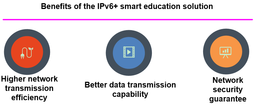
Solution networking
SRv6 is deployed on education national backbone networks, provincial networks, and MANs to provide L2/L3 VPN services and ensure intelligent traffic scheduling for key applications.
The core devices in backbone networks are all CR19000 series core routers. They are deployed with EVPN L3VPN over SRv6 to carry services, and use technologies such as G-SRv6, iFIT to satisfy users.
· Administrators can orchestrate traffic forwarding paths and the required value-added features through the unified portal.
· The controller obtains the configurations made by administrators from its northbound interface, and then delivers those configurations information to MANs and the core devices in cloud networks through NETCONF.
· The controller subscribes to iFIT measurement information through Telemetry, analyzes network quality information, and then visualizes the information.
· Source address validation systems such as SAVNET are deployed to ensure network security and reliability.
Figure175 Network diagram