- Table of Contents
- Related Documents
-
| Title | Size | Download |
|---|---|---|
| 01-VXLAN configuration | 529.94 KB |
VXLAN tunnel establishment and assignment
Assignment of traffic to VXLANs
Configuring basic VXLAN features
Assigning a VXLAN tunnel to a VXLAN
Mapping a Layer 3 interface to a VSI
Enabling local-MAC change logging
Configuring static remote-MAC address entries
Disabling remote-MAC address learning
Confining unknown-unicast floods to the local site
Setting the destination UDP port number of VXLAN packets
Configuring VXLAN packet check
Enabling ARP flood suppression
Enabling VXLAN fast forwarding
Displaying and maintaining VXLANs
Unicast-mode VXLAN configuration example
VXLAN IP gateways separated from VTEPs
Centralized VXLAN IP gateway deployment
Centralized VXLAN gateway group deployment
Distributed VXLAN IP gateway deployment
Configuration restrictions and guidelines
Configuring a centralized VXLAN IP gateway
Configuring a centralized VXLAN IP gateway group
Specifying a VTEP group as the gateway for an access layer VTEP
Configuring a distributed VXLAN IP gateway
Displaying and maintaining VXLAN IP gateway
VXLAN IP gateway configuration examples
Centralized VXLAN IP gateway configuration example
Distributed VXLAN IPv4 gateway configuration example
VXLAN overview
Virtual eXtensible LAN (VXLAN) is a MAC-in-UDP technology that provides Layer 2 connectivity between distant network sites across an IP network. VXLAN is typically used in data centers for multitenant services.
VXLAN provides the following benefits:
· Support for more virtual switched domains than VLANs—Each VXLAN is uniquely identified by a 24-bit VXLAN ID. The total number of VXLANs can reach 16777216 (224). This specification makes VXLAN a better choice than 802.1Q VLAN to isolate traffic for VMs.
· Easy deployment and maintenance—VXLAN requires deployment only on the edge devices of the transport network. Devices in the transport network perform typical Layer 3 forwarding.
The device supports only IPv4-based VXLAN. IPv6-based VXLAN is not supported.
VXLAN network model
As shown in Figure 1, a VXLAN is a virtual Layer 2 network (known as the overlay network) built on top of an existing physical Layer 3 network (known as the underlay network). The overlay network encapsulates inter-site Layer 2 frames into VXLAN packets and forwards the packets to the destination along the Layer 3 forwarding paths provided by the underlay network. The underlay network is transparent to tenants, and geographically dispersed sites of a tenant are merged into a Layer 2 network.
The transport edge devices assign VMs to different VXLANs, and then forward traffic between sites for VMs by using VXLAN tunnels.
The transport edge devices are VXLAN tunnel endpoints (VTEP). They can be servers that host VMs or independent network devices.
An H3C VTEP uses VSIs and VXLAN tunnels to provide VXLAN services.
· VSI—A virtual switch instance is a virtual Layer 2 switched domain. Each VSI provides switching services only for one VXLAN. VSIs learn MAC addresses and forward frames independently of one another. VMs in different sites have Layer 2 connectivity if they are in the same VXLAN.
· VXLAN tunnel—Logical point-to-point tunnels between VTEPs over the transport network. Each VXLAN tunnel can trunk multiple VXLANs.
VTEPs encapsulate VXLAN traffic in the VXLAN, outer UDP, and outer IP headers. The devices in the transport network forward VXLAN traffic only based on the outer IP header.
Figure 1 VXLAN network model

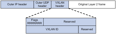
VXLAN packet format
As shown in Figure 2, a VTEP encapsulates a frame in the following headers:
· 8-byte VXLAN header—VXLAN information for the frame.
? Flags—If the I bit is 1, the VXLAN ID is valid. If the I bit is 0, the VXLAN ID is invalid. All other bits are reserved and set to 0.
? 24-bit VXLAN ID—Identifies the VXLAN of the frame. It is also called the virtual network identifier (VNI).
· 8-byte outer UDP header for VXLAN—The default VXLAN destination UDP port number is 4789.
· 20-byte outer IP header—Valid addresses of VTEPs or VXLAN multicast groups on the transport network. Devices in the transport network forward VXLAN packets based on the outer IP header.
Figure 2 VXLAN packet format
Working mechanisms
The VTEP uses the following process to forward an inter-site frame:
1. Assigns the frame to its matching VXLAN if the frame is sent between sites.
2. Performs MAC learning on the VXLAN's VSI.
3. Forwards the frame through VXLAN tunnels.
This section describes this process in detail. For intra-site frames in a VSI, the system performs typical Layer 2 forwarding.
VXLAN tunnel establishment and assignment
To provide Layer 2 connectivity for a VXLAN between two sites, you must create a VXLAN tunnel between the sites and assign the tunnel to the VXLAN.
VXLAN tunnel establishment
VXLAN supports manual VXLAN tunnel establishment. You must manually create a VXLAN tunnel interface and specify the tunnel source and destination IP addresses on the peer VTEPs.
VXLAN tunnel assignment
VXLAN supports manual VXLAN tunnel assignment. You must manually assign VXLAN tunnels to VXLANs.
Assignment of traffic to VXLANs
Traffic from the local site to a remote site
The VTEP uses a Layer 3 interface to match customer traffic on a site-facing interface. The VTEP assigns customer traffic to a VXLAN by mapping the Layer 3 interface to a VSI. A Layer 3 interface is identical to an attachment circuit (AC) in L2VPN.
Traffic from a remote site to the local site
When a frame arrives at a VXLAN tunnel, the VTEP uses the VXLAN ID in the frame to identify its VXLAN.
MAC learning
The VTEP performs source MAC learning on the VSI as a Layer 2 switch.
· For traffic from the local site to the remote site, the VTEP learns the source MAC address before VXLAN encapsulation.
· For traffic from the remote site to the local site, the VTEP learns the source MAC address after removing the VXLAN header.
A VSI's MAC address table includes the following types of MAC address entries:
· Local MAC—Dynamic MAC entries learned from the local site. The outgoing interfaces are site-facing interfaces on which the MAC addresses are learned. VXLAN does not support manual local-MAC entries.
· Remote MAC—MAC entries learned from a remote site, including static and dynamic MAC entries. The outgoing interfaces for the MAC addresses are VXLAN tunnel interfaces.
? Static—Manually added MAC entries.
? Dynamic—MAC entries learned in the data plane from incoming traffic on VXLAN tunnels. The learned MAC addresses are contained in the inner Ethernet header.
? OpenFlow—MAC entry issued by a remote controller through OpenFlow.
For a remote MAC address, the manual static entry has higher priority than the dynamic entry.
Traffic forwarding
A VTEP uses the following processes to forward traffic at Layer 2:
· Unicast process—Applies to destination-known unicast traffic.
· Flood process—Applies to multicast, broadcast, and unknown unicast traffic.
Unicast
The following process (see Figure 3) applies to a known unicast frame between sites:
1. The source VTEP encapsulates the Ethernet frame in the VXLAN/UDP/IP header.
In the outer IP header, the source IP address is the source VTEP's VXLAN tunnel source IP address. The destination IP address is the VXLAN tunnel destination IP address.
2. The source VTEP forwards the encapsulated packet out of the outgoing VXLAN tunnel interface found in the VSI's MAC address table.
3. The intermediate transport devices (P devices) forward the frame to the destination VTEP by using the outer IP header.
4. The destination VTEP removes the headers on top of the inner Ethernet frame. It then performs MAC address table lookup in the VXLAN's VSI to forward the frame out of the matching outgoing interface.

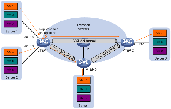
Flood
The VTEP floods a broadcast, multicast, or unknown unicast frame to all site-facing interfaces and VXLAN tunnels in the VXLAN, except for the incoming interface.
VXLAN supports the unicast mode for flood traffic. Unicast mode is also called head-end replication. The source VTEP replicates the flood frame, and then sends one replica to the destination IP address of each VXLAN tunnel in the VXLAN. See Figure 4.
Each destination VTEP floods the inner Ethernet frame to all the site-facing interfaces in the VXLAN. To avoid loops, the destination VTEPs do not flood the frame to VXLAN tunnels.
ARP flood suppression
ARP flood suppression reduces ARP request broadcasts by enabling the VTEP to reply to ARP requests on behalf of VMs.
As shown in Figure 5, this feature snoops ARP packets to populate the ARP flood suppression table with local and remote MAC addresses. If an ARP request has a matching entry, the VTEP replies to the request on behalf of the VM. If no match is found, the VTEP floods the request to both local and remote sites.
Figure 5 ARP flood suppression

ARP flood suppression uses the following workflow:
1. VM 1 sends an ARP request to obtain the MAC address of VM 7.
2. VTEP 1 creates a suppression entry for VM 1, and floods the ARP request in the VXLAN.
3. VTEP 2 and VTEP 3 de-encapsulate the ARP request. The VTEPs create a suppression entry for VM 1, and broadcast the request in the local site.
4. VM 7 sends an ARP reply.
5. VTEP 2 creates a suppression entry for VM 7 and forwards the ARP reply to VTEP 1.
6. VTEP 1 de-encapsulates the ARP reply, creates a suppression entry for VM 7, and forwards the ARP reply to VM 1.
7. VM 4 sends an ARP request to obtain the MAC address of VM 1 or VM 7.
8. VTEP 1 creates a suppression entry for VM 4 and replies to the ARP request.
9. VM 10 sends an ARP request to obtain the MAC address of VM 1.
10. VTEP 3 creates a suppression entry for VM 10 and replies to the ARP request.
VXLAN IP gateways
A VXLAN IP gateway provides Layer 3 forwarding services for VMs in VXLANs. A VXLAN IP gateway can be an independent device or be collocated with a VTEP. For more information about VXLAN IP gateway placement, see "Configuring VXLAN IP gateways."
Protocols and standards
RFC 7348, Virtual eXtensible Local Area Network (VXLAN): A Framework for Overlaying Virtualized Layer 2 Networks over Layer 3 Networks
Configuring basic VXLAN features
VXLAN configuration task list
|
Tasks at a glance |
Remarks |
|
(Required.) Creating a VXLAN on a VSI |
N/A |
|
(Required.) Configuring a VXLAN tunnel |
N/A |
|
(Required.) Assigning a VXLAN tunnel to a VXLAN |
To extend a VXLAN to remote sites, you must assign VXLAN tunnels to the VXLAN. |
|
(Required.) Mapping a Layer 3 interface to a VSI |
Perform this task to assign customer traffic to VXLANs. |
|
(Optional.) Managing MAC address entries |
N/A |
|
(Optional.) Confining unknown-unicast floods to the local site |
N/A |
|
(Optional.) Setting the destination UDP port number of VXLAN packets |
N/A |
|
(Optional.) Configuring VXLAN packet check |
Perform this task to check the UDP checksum of incoming VXLAN packets. |
|
(Optional.) Enabling ARP flood suppression |
N/A |
|
(Optional.) Enabling VXLAN fast forwarding |
N/A |
Creating a VXLAN on a VSI
|
Step |
Command |
Remarks |
|
1. Enter system view. |
system-view |
N/A |
|
2. Enable L2VPN. |
l2vpn enable |
By default, L2VPN is disabled. |
|
3. Create a VSI and enter VSI view. |
vsi vsi-name |
By default, no VSIs exist. |
|
4. (Optional.) Configure a VSI description. |
description text |
By default, a VSI does not have a description. |
|
5. Enable the VSI. |
undo shutdown |
By default, a VSI is enabled. |
|
6. (Optional.) Set the MTU for the VSI. |
mtu mtu |
The default MTU is 1500 bytes for a VSI. |
|
7. (Optional.) Set the broadcast or unknown unicast bandwidth restraints for the VSI. |
restrain { broadcast | unknown-unicast } bandwidth |
The default broadcast and unknown unicast bandwidth restraints are 5120 kbps. |
|
8. (Optional.) Enable MAC address learning for the VSI. |
mac-learning enable |
By default, MAC address learning is enabled for a VSI. |
|
9. (Optional.) Set a limit for the VSI's MAC address table. |
mac-table limit mac-limit |
By default, no limit is set for a VSI's MAC address table. |
|
10. Create a VXLAN and enter VXLAN view. |
vxlan vxlan-id |
By default, no VXLANs exist. You can create only one VXLAN on a VSI. The VXLAN ID must be unique for each VSI. |
Configuring a VXLAN tunnel
This task provides basic VXLAN tunnel configuration. For more information about tunnel configuration and commands, see Layer 3—IP Services Configuration Guide and Layer 3—IP Services Command Reference.
To configure a VXLAN tunnel:
|
Step |
Command |
Remarks |
|
1. Enter system view. |
system-view |
N/A |
|
2. Create a VXLAN tunnel interface and enter tunnel interface view. |
interface tunnel tunnel-number mode vxlan |
By default, no tunnel interfaces exist. The endpoints of a tunnel must use the same tunnel mode. |
|
3. Specify a source IP address or source interface for the tunnel. |
source { ipv4-address | interface-type interface-number } |
By default, no source IP address or source interface is specified for a tunnel. This step specifies the source IP address in the outer IP header of tunneled VXLAN packets. If an interface is specified, its primary IP address is used. |
|
4. Specify a destination IP address for the tunnel. |
destination ipv4-address |
By default, no destination IP address is specified for a tunnel. Specify the remote VTEP's IP address. This IP address will be the destination IP address in the outer IP header of tunneled VXLAN packets. As a best practice, do not configure multiple VXLAN tunnels to use the same source and destination IP addresses. |
Assigning a VXLAN tunnel to a VXLAN
To provide Layer 2 connectivity for a VXLAN between two sites, you must assign the VXLAN tunnel between the sites to the VXLAN.
You can assign multiple VXLAN tunnels to a VXLAN, and configure a VXLAN tunnel to trunk multiple VXLANs. For a unicast-mode VXLAN, the system floods unknown unicast, multicast, and broadcast traffic to each tunnel associated with the VXLAN.
To assign a VXLAN tunnel to a VXLAN:
|
Step |
Command |
Remarks |
|
1. Enter system view. |
system-view |
N/A |
|
2. Enter VSI view. |
vsi vsi-name |
N/A |
|
3. Enter VXLAN view. |
vxlan vxlan-id |
N/A |
|
4. Assign a VXLAN tunnel to the VXLAN. |
tunnel tunnel-number |
By default, a VXLAN does not contain any VXLAN tunnels. For full Layer 2 connectivity in the VXLAN, make sure the VXLAN contains the VXLAN tunnel between each pair of sites in the VXLAN. |
Mapping a Layer 3 interface to a VSI
To assign the customer traffic on a Layer 3 interface to a VXLAN, map the interface to the VXLAN's VSI. The VSI uses its MAC address table to forward the customer traffic.
To map a Layer 3 interface to a VSI:
|
Step |
Command |
Remarks |
|
1. Enter system view. |
system-view |
N/A |
|
2. Enter Layer 3 interface view. |
interface interface-type interface-number |
N/A |
|
3. Map the Layer 3 interface to a VSI. |
xconnect vsi vsi-name [ track track-entry-number&<1-3> ] |
By default, a Layer 3 interface is not mapped to any VSI. |
Managing MAC address entries
With VXLAN, local MAC addresses are learned dynamically. You can log MAC changes, but you cannot manually add local MAC addresses.
Remote-MAC address entries include the following types:
· Manually created static entries.
· Dynamic entries learned in the data plane.
· MAC entry issued by a remote controller through OpenFlow.
Enabling local-MAC change logging
Local-MAC change logging enables the VXLAN module to send a log message to the information center when a local MAC address is added or removed.
With the information center, you can set log message filtering and output rules, including output destinations. For more information about configuring the information center, see Network Management and Monitoring Configuration Guide.
To enable local-MAC change logging:
|
Step |
Command |
Remarks |
|
1. Enter system view. |
system-view |
N/A |
|
2. Enable local-MAC change logging. |
vxlan local-mac report |
By default, local-MAC change logging is disabled. |
Configuring static remote-MAC address entries
|
Step |
Command |
Remarks |
|
1. Enter system view. |
system-view |
N/A |
|
2. Add a static remote entry. |
mac-address static mac-address interface tunnel tunnel-number vsi vsi-name |
By default, VXLAN VSIs do not have static remote-MAC address entries. For the setting to take effect, make sure the VSI's VXLAN has been created and specified on the VXLAN tunnel. |
Disabling remote-MAC address learning
|
Step |
Command |
Remarks |
|
1. Enter system view. |
system-view |
N/A |
|
2. Disable remote-MAC address learning. |
vxlan tunnel mac-learning disable |
By default, remote-MAC address learning is enabled. When network attacks occur, disable remote-MAC address learning to prevent the device from learning incorrect remote MAC addresses. You can manually add static remote-MAC address entries. |
Confining unknown-unicast floods to the local site
By default, the VTEP floods unknown unicast frames received from the local site to the following interfaces in the frame's VXLAN:
· All site-facing interfaces except for the incoming interface.
· All VXLAN tunnel interfaces.
To confine unknown-unicast floods to site-facing interfaces for a VXLAN:
|
Step |
Command |
Remarks |
|
|
1. Enter system view. |
system-view |
N/A |
|
|
2. Enter VSI view. |
vsi vsi-name |
N/A |
|
|
3. Disable the VSI to flood unknown unicast traffic to VXLAN tunnel interfaces. |
flooding disable |
By default, unknown unicast traffic is flooded to all interfaces in the VXLAN, except for the incoming interface. |
|
|
4. (Optional.) Enable selective flood for a MAC address. |
selective-flooding mac-address mac-address |
By default, selective flood is disabled. Use this feature to exclude a remote MAC address from the flood suppression done by using the flooding disable command. The VTEP will flood the frames destined for the specified MAC address to remote sites when unknown-unicast floods are confined to the local site. |
|
Setting the destination UDP port number of VXLAN packets
|
Step |
Command |
Remarks |
|
|
1. Enter system view. |
system-view |
N/A |
|
|
2. Set a destination UDP port for VXLAN packets. |
vxlan udp-port port-number |
By default, the destination UDP port number is 4789 for VXLAN packets. You must configure the same destination UDP port number on all VTEPs in a VXLAN. |
|
Configuring VXLAN packet check
The device can check the UDP checksum of each received VXLAN packet.
The device always sets the UDP checksum of VXLAN packets to zero. For compatibility with third-party devices, a VXLAN packet can pass the check if its UDP checksum is zero or correct. If its UDP checksum is incorrect, the VXLAN packet fails the check and is dropped.
To configure VXLAN packet check:
|
Step |
Command |
Remarks |
|
1. Enter system view. |
system-view |
N/A |
|
2. Enable the VTEP to drop VXLAN packets that fail UDP checksum check. |
vxlan invalid-udp-checksum discard |
By default, the VTEP does not check the UDP checksum of VXLAN packets. |
Enabling ARP flood suppression
Use ARP flood suppression to reduce ARP request broadcasts.
The aging timer is fixed at 25 minutes for ARP flood suppression entries. If the suppression table is full, the VTEP stops learning new entries. For the VTEP to learn new entries, you must wait for old entries to age out, or use the reset arp suppression vsi command to clear the table.
If the flooding disable command is configured, set the MAC aging timer to a higher value than the aging timer for ARP flood suppression entries on all VTEPs. This setting prevents the traffic blackhole that occurs when a MAC address entry ages out before its ARP flood suppression entry ages out.
To set the MAC aging timer, use the mac-address timer command.
To enable ARP flood suppression:
|
Step |
Command |
Remarks |
|
1. Enter system view. |
system-view |
N/A |
|
2. Enter VSI view. |
vsi vsi-name |
N/A |
|
3. Enable ARP flood suppression. |
arp suppression enable |
By default, ARP flood suppression is disabled. |
Enabling VXLAN fast forwarding
VXLAN fast forwarding enables the device to bypass QoS and security services when the device forwards data traffic over VXLAN tunnels based on the software. As a best practice, enable this feature to improve forwarding speed only when QoS and security services are not configured on the following interfaces:
· VSI interfaces.
· Traffic outgoing interfaces for VXLAN tunnels.
When VXLAN fast forwarding is enabled, a VXLAN tunnel cannot use ECMP routes to load share traffic. Instead, it selects one route from the ECMP routes to forward VXLAN packets.
To enable VXLAN fast forwarding:
|
Step |
Command |
Remarks |
|
1. Enter system view. |
system-view |
N/A |
|
2. Enable VXLAN fast forwarding. |
vxlan fast-forwarding enable |
By default, VXLAN fast forwarding is disabled. |
Displaying and maintaining VXLANs
Execute display commands in any view and reset commands in user view.
|
Task |
Command |
|
Display ARP flood suppression entries on VSIs (in standalone mode). |
display arp suppression vsi [ name vsi-name ] [ slot slot-number ] [ count ] |
|
Display ARP flood suppression entries on VSIs (in IRF mode). |
display arp suppression vsi [ name vsi-name ] [ chassis chassis-number slot slot-number ] [ count ] |
|
Display L2VPN information for Layer 3 interfaces that are mapped to VSIs. |
display l2vpn interface [ vsi vsi-name | interface-type interface-number ] [ verbose ] |
|
Display MAC address entries for VSIs. |
display l2vpn mac-address [ vsi vsi-name ] [ dynamic ] [ count ] |
|
Display information about VSIs. |
display l2vpn vsi [ name vsi-name ] [ verbose ] |
|
Display information about tunnel interfaces. |
display interface [ tunnel [ number ] ] [ brief [ description | down ] ] |
|
Display VXLAN tunnel information for VXLANs. |
display vxlan tunnel [ vxlan vxlan-id ] |
|
Clear ARP flood suppression entries on VSIs. |
reset arp suppression vsi [ name vsi-name ] |
|
Clear dynamic MAC address entries on VSIs. |
reset l2vpn mac-address [ vsi vsi-name ] |
|
|
NOTE: For more information about the display interface tunnel command, see tunneling commands in Layer 3—IP Services Command Reference. |
VXLAN configuration examples
Unicast-mode VXLAN configuration example
Network requirements
As shown in Figure 6:
· Configure VXLAN 10 as a unicast-mode VXLAN on Router A, Router B, and Router C to provide Layer 2 connectivity for the VMs across the network sites.
· Manually establish VXLAN tunnels and assign the tunnels to VXLAN 10.
· Enable remote-MAC address learning.

Configuration procedure
1. Configure IP addresses and unicast routing settings:
# Assign IP addresses to interfaces, as shown in Figure 6. (Details not shown.)
# Configure OSPF on all transport network routers (Routers A through D). (Details not shown.)
2. Configure Router A:
# Enable L2VPN.
<RouterA> system-view
[RouterA] l2vpn enable
# Create the VSI vpna and VXLAN 10.
[RouterA] vsi vpna
[RouterA-vsi-vpna] vxlan 10
[RouterA-vsi-vpna-vxlan-10] quit
[RouterA-vsi-vpna] quit
# Assign an IP address to Loopback 0. The IP address will be used as the source IP address of the VXLAN tunnels to Router B and Router C.
[RouterA] interface loopback 0
[RouterA-Loopback0] ip address 1.1.1.1 255.255.255.255
[RouterA-Loopback0] quit
# Create a VXLAN tunnel to Router B. The tunnel interface name is Tunnel 1.
[RouterA] interface tunnel 1 mode vxlan
[RouterA-Tunnel1] source 1.1.1.1
[RouterA-Tunnel1] destination 2.2.2.2
[RouterA-Tunnel1] quit
# Create a VXLAN tunnel to Router C. The tunnel interface name is Tunnel 2.
[RouterA] interface tunnel 2 mode vxlan
[RouterA-Tunnel2] source 1.1.1.1
[RouterA-Tunnel2] destination 3.3.3.3
[RouterA-Tunnel2] quit
# Assign Tunnel 1 and Tunnel 2 to VXLAN 10.
[RouterA] vsi vpna
[RouterA-vsi-vpna] vxlan 10
[RouterA-vsi-vpna-vxlan-10] tunnel 1
[RouterA-vsi-vpna-vxlan-10] tunnel 2
[RouterA-vsi-vpna-vxlan-10] quit
[RouterA-vsi-vpna] quit
# Map GigabitEthernet 1/1/1 to the VSI vpna.
[RouterA] interface gigabitethernet 1/1/1
[RouterA-GigabitEthernet1/1/1] xconnect vsi vpna
[RouterA-GigabitEthernet1/1/1] quit
3. Configure Router B:
# Enable L2VPN.
<RouterB> system-view
[RouterB] l2vpn enable
# Create the VSI vpna and VXLAN 10.
[RouterB] vsi vpna
[RouterB-vsi-vpna] vxlan 10
[RouterB-vsi-vpna-vxlan-10] quit
[RouterB-vsi-vpna] quit
# Assign an IP address to Loopback 0. The IP address will be used as the source IP address of the VXLAN tunnels to Router A and Router C.
[RouterB] interface loopback 0
[RouterB-Loopback0] ip address 2.2.2.2 255.255.255.255
[RouterB-Loopback0] quit
# Create a VXLAN tunnel to Router A. The tunnel interface name is Tunnel 2.
[RouterB] interface tunnel 2 mode vxlan
[RouterB-Tunnel2] source 2.2.2.2
[RouterB-Tunnel2] destination 1.1.1.1
[RouterB-Tunnel2] quit
# Create a VXLAN tunnel to Router C. The tunnel interface name is Tunnel 3.
[RouterB] interface tunnel 3 mode vxlan
[RouterB-Tunnel3] source 2.2.2.2
[RouterB-Tunnel3] destination 3.3.3.3
[RouterB-Tunnel3] quit
# Assign Tunnel 2 and Tunnel 3 to VXLAN 10.
[RouterB] vsi vpna
[RouterB-vsi-vpna] vxlan 10
[RouterB-vsi-vpna-vxlan-10] tunnel 2
[RouterB-vsi-vpna-vxlan-10] tunnel 3
[RouterB-vsi-vpna-vxlan-10] quit
[RouterB-vsi-vpna] quit
# Map GigabitEthernet 1/1/1 to the VSI vpna.
[RouterB] interface gigabitethernet 1/1/1
[RouterB-GigabitEthernet1/1/1] xconnect vsi vpna
[RouterB-GigabitEthernet1/1/1] quit
4. Configure Router C:
# Enable L2VPN.
<RouterC> system-view
[RouterC] l2vpn enable
# Create the VSI vpna and VXLAN 10.
[RouterC] vsi vpna
[RouterC-vsi-vpna] vxlan 10
[RouterC-vsi-vpna-vxlan-10] quit
[RouterC-vsi-vpna] quit
# Assign an IP address to Loopback 0. The IP address will be used as the source IP address of the VXLAN tunnels to Router A and Router B.
[RouterC] interface loopback 0
[RouterC-Loopback0] ip address 3.3.3.3 255.255.255.255
[RouterC-Loopback0] quit
# Create a VXLAN tunnel to Router A. The tunnel interface name is Tunnel 1.
[RouterC] interface tunnel 1 mode vxlan
[RouterC-Tunnel1] source 3.3.3.3
[RouterC-Tunnel1] destination 1.1.1.1
[RouterC-Tunnel1] quit
# Create a VXLAN tunnel to Router B. The tunnel interface name is Tunnel 3.
[RouterC] interface tunnel 3 mode vxlan
[RouterC-Tunnel3] source 3.3.3.3
[RouterC-Tunnel3] destination 2.2.2.2
[RouterC-Tunnel3] quit
# Assign Tunnel 1 and Tunnel 3 to VXLAN 10.
[RouterC] vsi vpna
[RouterC-vsi-vpna] vxlan 10
[RouterC-vsi-vpna-vxlan-10] tunnel 1
[RouterC-vsi-vpna-vxlan-10] tunnel 3
[RouterC-vsi-vpna-vxlan-10] quit
[RouterC-vsi-vpna] quit
# Map GigabitEthernet 1/1/1 to the VSI vpna.
[RouterC] interface gigabitethernet 1/1/1
[RouterC-GigabitEthernet1/1/1] xconnect vsi vpna
[RouterC-GigabitEthernet1/1/1] quit
Verifying the configuration
1. Verify the VXLAN settings on the VTEPs. This example uses Router A.
# Verify that the VXLAN tunnel interfaces on the VTEP are up.
[RouterA] display interface tunnel 1
Tunnel1
Current state: UP
Line protocol state: UP
Description: Tunnel1 Interface
Bandwidth: 64kbps
Maximum transmission unit: 64000
Internet protocol processing: Disabled
Output queue - Urgent queuing: Size/Length/Discards 0/100/0
Output queue - Protocol queuing: Size/Length/Discards 0/500/0
Output queue - FIFO queuing: Size/Length/Discards 0/75/0
Last clearing of counters: Never
Tunnel source 1.1.1.1, destination 2.2.2.2
Tunnel protocol/transport UDP_VXLAN/IP
Last 300 seconds input rate: 0 bytes/sec, 0 bits/sec, 0 packets/sec
Last 300 seconds output rate: 0 bytes/sec, 0 bits/sec, 0 packets/sec
Input: 0 packets, 0 bytes, 0 drops
Output: 0 packets, 0 bytes, 0 drops
# Verify that the VXLAN tunnels have been assigned to the VXLAN.
[RouterA] display l2vpn vsi verbose
VSI Name: vpna
VSI Index : 0
VSI State : Up
MTU : 1500
Bandwidth : -
Broadcast Restrain : 5120 kbps
Multicast Restrain : -
Unknown Unicast Restrain: 5120 kbps
MAC Learning : Enabled
MAC Table Limit : Unlimited
MAC Learning rate : -
Drop Unknown : -
Flooding : Enabled
VXLAN ID : 10
Tunnels:
Tunnel Name Link ID State Type Flood proxy
Tunnel1 0x5000001 Up Manual Disabled
Tunnel2 0x5000002 Up Manual Disabled
ACs:
AC Link ID State
GE1/1/1 0 Up
# Verify that the VTEP has learned the MAC addresses of remote VMs.
<RouterA> display l2vpn mac-address
MAC Address State VSI Name Link ID/Name Aging
cc3e-5f9c-6cdb Dynamic vpna Tunnel1 Aging
cc3e-5f9c-23dc Dynamic vpna Tunnel2 Aging
--- 2 mac address(es) found ---
2. Verify that VM 1, VM 2, and VM 3 can ping each other. (Details not shown.)
Configuring VXLAN IP gateways
Overview
The following are available IP gateway placement designs for VXLANs:
· VXLAN IP gateways separated from VTEPs—Use a VXLAN-unaware device as a gateway to the external network for VXLANs. On the gateway, you do not need to configure VXLAN settings.
· VXLAN IP gateways collocated with VTEPs—Include the following placement designs:
? Centralized VXLAN IP gateway deployment—Use one VTEP to provide Layer 3 forwarding for VXLANs. Typically, the gateway-collocated VTEP connects to other VTEPs and the external network. To use this design, make sure the IP gateway has sufficient bandwidth and processing capability. Centralized VXLAN IP gateways provide services only for IPv4 networks.
? Centralized VXLAN gateway group deployment—Use one VTEP group that contains redundant centralized VXLAN IP gateways to provide reliable gateway services for VXLANs.
? Distributed VXLAN IP gateway deployment—Deploy one VXLAN IP gateway on each VTEP to provide Layer 3 forwarding for VXLANs at their respective sites. This design distributes the Layer 3 traffic load across VTEPs. However, its configuration is more complex than the centralized VXLAN IP gateway design. Distributed gateways can provide services only for IPv4 networks.
In a collocation design, the VTEPs use virtual Layer 3 VSI interfaces as gateway interfaces to provide services for VXLANs.
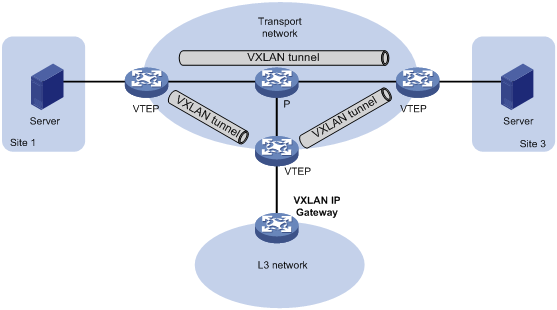
VXLAN IP gateways separated from VTEPs
As shown in Figure 7, an independent VXLAN IP gateway connects a Layer 3 network to a VTEP. VMs send Layer 3 traffic in Layer 2 frames to the gateway through VXLAN tunnels. When the tunneled VXLAN packets arrive, the VTEP terminates the VXLANs and forwards the inner frames to the gateway. In this gateway placement design, the VTEP does not perform Layer 3 forwarding for VXLANs.
Figure 7 VXLAN IP gateway separated from VTEPs
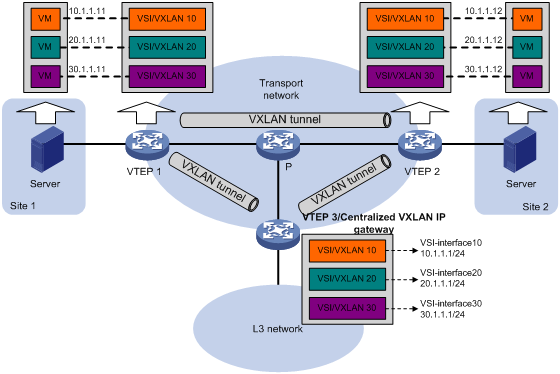
Centralized VXLAN IP gateway deployment
As shown in Figure 8, a VTEP acts as a gateway for VMs in the VXLANs. The VTEP both terminates the VXLANs and performs Layer 3 forwarding for the VMs.
Figure 8 Centralized VXLAN IP gateway placement design

As shown in Figure 9, the network uses the following process to forward Layer 3 traffic from VM 10.1.1.11 to the Layer 3 network:
1. The VM sends an ARP request to obtain the MAC address of the gateway (VTEP 3) at 10.1.1.1.
2. VTEP 1 floods the ARP request to all remote VTEPs.
3. VTEP 3 de-encapsulates the ARP request, creates an ARP entry for the VM, and sends an ARP reply to the VM.
4. VTEP 1 forwards the ARP reply to the VM.
5. The VM learns the MAC address of the gateway, and sends the Layer 3 traffic to the gateway.
6. VTEP 3 removes the VXLAN encapsulation and inner Ethernet header for the traffic, and forwards the traffic to the destination node.
Inter-VXLAN forwarding is the same as this process except for the last step. At the last step of inter-VLAN forwarding, the gateway replaces the source-VXLAN encapsulation with the destination-VXLAN encapsulation, and then forwards the traffic.
Figure 9 Example of centralized VXLAN IP gateway deployment
Centralized VXLAN gateway group deployment
As shown in Figure 10, a VTEP group uses redundant centralized VXLAN IP gateways to provide reliable gateway services for VMs in the VXLANs. All member VTEPs in the group participate in Layer 3 forwarding and load share traffic between the Layer 3 network and the VXLANs. This design distributes intense processing burden among multiple VTEPs and prevents single points of failure.
Figure 10 Example of centralized VXLAN IP gateway group deployment
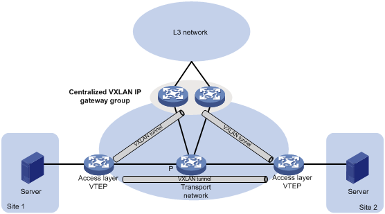
The VTEP group is a virtual gateway that provides services at a group IP address. Access layer VTEPs set up VXLAN tunnels to the group IP address for data traffic forwarding. Each VTEP in the group automatically uses its member IP address to set up tunnels to the other member VTEPs and access layer VTEPs. The tunnels are used to transmit protocol packets and synchronize ARP entries.
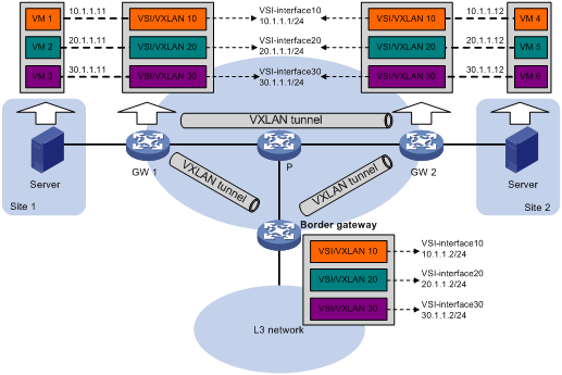
Distributed VXLAN IP gateway deployment
As shown in Figure 11, each site's VTEP acts as a gateway to perform Layer 3 forwarding for the VXLANs of the local site. A VTEP acts as a border gateway to the Layer 3 network for the VXLANs. The VTEPs perform Layer 3 forwarding based on ARP entries.
|
|
IMPORTANT: The site-connected gateways are called distributed gateways. On the distributed gateways, you must enable local proxy ARP. |
Figure 11 Distributed VXLAN IP gateway placement design

Figure 12 shows an example of distributed VXLAN IP gateway deployment. This section uses this figure to describe the forwarding processes for intra-VXLAN traffic, inter-VXLAN traffic, and traffic from a VXLAN to an external network. In these processes, VTEPs use dynamically learned ARP entries.
Figure 12 Example of distributed VXLAN IP gateway deployment
Intra-VXLAN traffic forwarding between sites
As shown in Figure 12, the network uses the following process to forward traffic in a VXLAN between sites (for example, from VM 1 to VM 4 in VXLAN 10):
1. VM 1 sends an ARP request to obtain the MAC address of VM 4.
2. GW 1 performs the following operations:
a. Creates an ARP entry for VM 1 and replies with the MAC address of VSI-interface 10 (the gateway interface for VXLAN 10).
b. Replaces the sender MAC address of the ARP request with the MAC address of VSI-interface 10, and then floods the request to all remote VTEPs.
3. VM 1 creates an ARP entry for VM 4. The MAC address in the entry is the MAC address of VSI-interface 10 on GW 1.
4. GW 2 (the VTEP for VM 4) performs the following operations:
a. De-encapsulates the ARP request and creates an ARP entry for VM 1. The entry contains VM 1's IP address (10.1.1.11), the MAC address of VSI-interface 10 on GW 1, and the incoming tunnel interface.
b. Replaces the sender MAC address of the request with the MAC address of VSI-interface 10 on GW 2, and then floods the request to the local site in VXLAN 10.
5. VM 4 creates an ARP entry for VM 1, and then sends a reply to GW 2. The MAC address in the ARP entry is the MAC address of VSI-interface 10 on GW 2.
6. GW 2 performs the following operations:
a. Creates an ARP entry for VM 4.
b. Replaces the sender MAC address of the request with the MAC address of VSI-interface 10 on GW 2, and sends the reply to GW 1.
7. GW 1 de-encapsulates the ARP request and creates an ARP entry for VM 4. The entry contains VM 4's IP address (10.1.1.12), the MAC address of VSI-interface 10 on GW 2, and the incoming tunnel interface.
8. For subsequent traffic between VM 1 and VM 4, GW 1 and GW 2 use their respective ARP tables to make the forwarding decision.
Inter-VXLAN traffic forwarding between sites
As shown in Figure 12, the network uses the following process to forward traffic between VXLANs (for example, from VM 1 in VXLAN 10 to VM 5 in VXLAN 20):
1. VM 1 sends an ARP request to obtain the MAC address of the gateway at 10.1.1.1.
2. GW 1 creates an ARP entry for VM 1 and replies with the MAC address of VSI-interface 10 (the gateway interface for VXLAN 10).
3. VM 1 sends the packet destined for VM 5 to GW 1.
4. GW 1 sends an ARP request to the local site and remote sites to obtain the MAC address of VM 5. In the ARP request, the sender IP address is 20.1.1.1, and the sender MAC address is the MAC address of VSI-interface 20 on GW 1.
5. GW 2 performs the following operations:
a. De-encapsulates the ARP request and creates an ARP entry for GW 1. The entry contains IP address 20.1.1.1 and MAC address of VSI-interface 20 on GW 1, and the incoming tunnel interface.
b. Replaces the sender MAC address of the request with the MAC address of VSI-interface 20 on GW 2, and then floods the request to the local site in VXLAN 20.
6. VM 5 creates an ARP entry for GW 2, and then sends a reply to GW 2. The entry contains the IP address (20.1.1.1) and MAC address of VSI-interface 20 on GW 2).
7. GW 2 performs the following operations:
a. Creates an ARP entry for VM 5.
b. Replaces the sender MAC address in the request with the MAC address of VSI-interface 20 on GW 2, and then sends the reply to GW 1.
8. GW 1 de-encapsulates the ARP request and creates an ARP entry for VM 5. The entry contains VM 5's IP address 20.1.1.12, the MAC address of VSI-interface 20 on GW 2, and the incoming tunnel interface.
9. For subsequent traffic between VM 1 and VM 4, GW 1 and GW 2 use their respective ARP tables to make the forwarding decision.
VXLAN-to-external network traffic forwarding
As shown in Figure 12, the network uses the following process to forward traffic from a VXLAN to the Layer 3 network (for example, from VM 1 to the host at 50.1.1.1):
1. VM 1 sends an ARP request to obtain the MAC address of the gateway at 10.1.1.1.
2. GW 1 creates an ARP entry for VM 1 and replies with the MAC address of VSI-interface 10 (the gateway interface for VXLAN 10).
3. VM 1 sends a packet destined for the host to GW 1.
4. GW 1 performs the following operations:
a. Searches the IP routing policies or routing table for the next hop. In this example, the next hop for the packet is 10.1.1.2 (the border gateway).
b. Floods an ARP request to the local and remote sites in VXLAN 10 to obtain the MAC address of 10.1.1.2.
5. The border gateway de-encapsulates the ARP request, creates an ARP entry for GW 1, and tunnels a reply to GW 1.
6. GW 1 de-encapsulates the ARP reply and creates an ARP entry for 10.1.1.2.
7. GW 1 sends the packet destined for the host to the border gateway.
8. The border gateway de-encapsulates the packet and forwards it to the host.
Configuration restrictions and guidelines
Do not configure centralized gateway settings and centralized gateway group settings together on a device.
Configuration prerequisites
Before you configure a centralized or distributed VXLAN IP gateway, you must perform the following tasks on VTEPs:
· Create VSIs and VXLANs.
· Configure VXLAN tunnels and assign them to VXLANs.
Configuring a centralized VXLAN IP gateway
|
Step |
Command |
Remarks |
|
|
1. Enter system view. |
system-view |
N/A |
|
|
2. Create a VSI interface and enter VSI interface view. |
interface vsi-interface vsi-interface-id |
By default, no VSI interfaces exist. |
|
|
3. Assign an IPv4 address to the VSI interface. |
ip address ip-address { mask | mask-length } |
By default, no IPv4 address is assigned to a VSI interface. |
|
|
4. Return to system view. |
quit |
N/A |
|
|
5. Enter VSI view. |
vsi vsi-name |
N/A |
|
|
6. Specify a gateway interface for the VSI. |
gateway vsi-interface vsi-interface-id |
By default, no gateway interface is specified for a VSI. |
|
Configuring a centralized VXLAN IP gateway group
Configuring a VTEP group
Make sure the member VTEPs use the same VXLAN settings.
Configure a VTEP group on a member VTEP:
|
Step |
Command |
Remarks |
|
1. Enter system view. |
system-view |
N/A |
|
2. Create a VSI interface and enter VSI interface view. |
interface vsi-interface vsi-interface-id |
By default, no VSI interfaces exist. You must create the same VSI interface on all VTEPs in the VTEP group. |
|
3. Assign an IP address to the VSI interface. |
ip address ip-address { mask | mask-length } |
By default, no IP address is assigned to a VSI interface. You must assign the same IP address to the VSI interface on each VTEP in the VTEP group. |
|
4. Assign a MAC address to the VSI interface. |
mac-address mac-address |
By default, VSI interfaces use the MAC address of aggregate interfaces. You must assign the same MAC address to the VSI interface on each VTEP in the VTEP group. |
|
5. Return to system view. |
quit |
N/A |
|
6. Enter VSI view. |
vsi vsi-name |
N/A |
|
7. Specify a gateway interface for the VSI. |
gateway vsi-interface vsi-interface-id |
By default, no gateway interface is specified for a VSI. |
|
8. Return to system view. |
quit |
N/A |
|
9. Assign the local VTEP to a VTEP group and specify the member IP address for the VTEP. |
vtep group group-ip member local member-ip |
By default, a VTEP is not assigned to any VTEP group. Perform this task on all member VTEPs in the VTEP group. The IP address specified by the member-ip argument must already exist on the local VTEP. You must configure a routing protocol to advertise the IP address in the transport network. Member VTEPs in a VTEP group cannot use the group IP address or share an IP address. |
|
10. Specify all the other VTEPs in the VTEP group. |
vtep group group-ip member remote member-ip&<1-8> |
By default, no VTEP group is specified. Perform this task on all member VTEPs in the VTEP group. |
Specifying a VTEP group as the gateway for an access layer VTEP
Before you specify a VTEP group on an access layer VTEP, perform the following tasks on the VTEP:
· Configure VSIs and VXLANs.
· Set up VXLAN tunnels to remote sites and the VTEP group, and assign the tunnels to VXLANs.
To specify a VTEP group as the gateway for an access layer VTEP:
|
Step |
Command |
Remarks |
|
1. Enter system view. |
system-view |
N/A |
|
2. Specify a VTEP group and all its member VTEPs. |
vtep group group-ip member remote member-ip&<1-8> |
By default, no VTEP group is specified. |
Configuring a distributed VXLAN IP gateway
For a VXLAN that requires access to the external network, specify the VXLAN's VSI interface on the border gateway as the next hop by using one of the following methods:
· Configure a static route.
· Configure a routing policy, and apply the policy by using the apply default-next-hop command. For more information about configuring routing policies, see routing policy configuration in Layer 3—IP Routing Configuration Guide.
ARP flood suppression is not supported on distributed VXLAN IP gateways. For more information about ARP flood suppression, see "Enabling ARP flood suppression."
To configure a distributed VXLAN IP gateway:
|
Step |
Command |
Remarks |
|
1. Enter system view. |
system-view |
N/A |
|
2. Create a VSI interface and enter VSI interface view. |
interface vsi-interface vsi-interface-id |
By default, no VSI interfaces exist. |
|
3. Assign an IPv4 address to the VSI interface. |
ip address ip-address { mask | mask-length } [ sub ] |
By default, no IPv4 address is assigned to a VSI interface. This interface will be used as a gateway for VXLANs. You can assign one primary IP address and multiple secondary IP addresses. |
|
4. Specify the VSI interface as a distributed gateway. |
distributed-gateway local |
By default, a VSI interface is not a distributed gateway. |
|
5. Enable local proxy ARP. |
local-proxy-arp enable [ ip-range startIP to endIP ] |
By default, local proxy ARP is disabled. For more information about the command, see Layer 3—IP Services Command Reference. |
|
6. Return to system view. |
quit |
N/A |
|
7. Enter VSI view. |
vsi vsi-name |
N/A |
|
8. Specify the VSI interface as the gateway interface for the VSI. |
gateway vsi-interface vsi-interface-id |
By default, no gateway interface is specified for a VSI. |
|
9. Assign a subnet to the VSI. |
gateway subnet ipv4-address wildcard-mask |
By default, no subnet exists on a VSI. You must configure this command on VSIs that share a gateway interface. This command enables the VSI interface to identify the VSI of a packet. You can assign a maximum of eight IPv4 subnets to a VSI. Make sure these subnets are on the same network as one of the IP addresses on the gateway interface. For VSIs that share a gateway interface, the subnets must be unique. If you remove the gateway interface from the VSI, the VSI's subnet settings are automatically deleted. |
Configuring a VSI interface
|
Step |
Command |
Remarks |
|
|
1. Enter system view. |
system-view |
N/A |
|
|
2. Enter VSI interface view. |
interface vsi-interface vsi-interface-id |
N/A |
|
|
3. Assign a MAC address to the VSI interface. |
mac-address mac-address |
By default, VSI interfaces use the MAC address of aggregate interfaces. |
|
|
4. (Optional.) Configure a description for the VSI interface. |
description text |
The default description of a VSI interface is interface-name plus Interface (for example, Vsi-interface100 Interface). |
|
|
5. (Optional.) Set the MTU for the VSI interface. |
mtu mtu-value |
The default MTU is 1500 bytes. |
|
|
6. (Optional.) Set the expected bandwidth for the VSI interface. |
bandwidth bandwidth-value |
The default expected bandwidth (in kbps) equals the interface baudrate divided by 1000. |
|
|
7. Restore the default settings on the interface |
default |
N/A |
|
|
8. Bring up the interface. |
undo shutdown |
By default, a VSI interface is up. |
|
Displaying and maintaining VXLAN IP gateway
Execute display commands in any view and reset commands in user view.
|
Task |
Command |
|
Display information about VSI interfaces. |
display interface [ vsi-interface [ vsi-interface-id ] ] [ brief [ description | down ] ] |
|
Clear statistics on VSI interfaces. |
reset counters interface [ vsi-interface [ vsi-interface-id ] ] |
VXLAN IP gateway configuration examples
Centralized VXLAN IP gateway configuration example
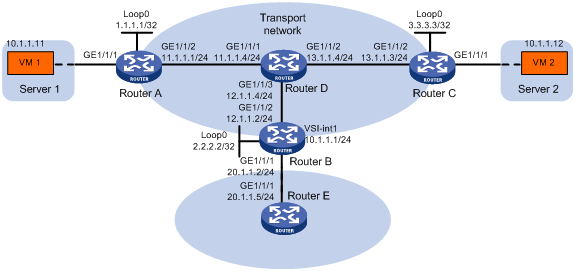
Network requirements
As shown in Figure 13:
· Configure VXLAN 10 as a unicast-mode VXLAN on Router A, Router B, and Router C to provide connectivity for the VMs across the network sites.
· Configure a centralized VXLAN IP gateway on Router B to provide gateway services for VXLAN 10.
· Manually establish VXLAN tunnels and assign the tunnels to VXLAN 10.
· Enable remote-MAC address learning.
Configuration procedure
1. On VM 1 and VM 2, specify 10.1.1.1 as the gateway address. (Details not shown.)
2. Configure IP addresses and unicast routing settings:
# Assign IP addresses to interfaces, as shown in Figure 13. (Details not shown.)
# Configure OSPF on all transport network routers (Routers A through D). (Details not shown.)
# Configure OSPF to advertise routes to networks 10.1.1.0/24 and 20.1.1.0/24 on Router B and Router E. (Details not shown.)
3. Configure Router A:
# Enable L2VPN.
<RouterA> system-view
[RouterA] l2vpn enable
# Create the VSI vpna and VXLAN 10.
[RouterA] vsi vpna
[RouterA-vsi-vpna] vxlan 10
[RouterA-vsi-vpna-vxlan-10] quit
[RouterA-vsi-vpna] quit
# Assign an IP address to Loopback 0. The IP address will be used as the source IP address of the VXLAN tunnels to Router B and Router C.
[RouterA] interface loopback 0
[RouterA-Loopback0] ip address 1.1.1.1 255.255.255.255
[RouterA-Loopback0] quit
# Create a VXLAN tunnel to Router B. The tunnel interface name is Tunnel 1.
[RouterA] interface tunnel 1 mode vxlan
[RouterA-Tunnel1] source 1.1.1.1
[RouterA-Tunnel1] destination 2.2.2.2
[RouterA-Tunnel1] quit
# Create a VXLAN tunnel to Router C. The tunnel interface name is Tunnel 2.
[RouterA] interface tunnel 2 mode vxlan
[RouterA-Tunnel2] source 1.1.1.1
[RouterA-Tunnel2] destination 3.3.3.3
[RouterA-Tunnel2] quit
# Assign Tunnel 1 and Tunnel 2 to VXLAN 10.
[RouterA] vsi vpna
[RouterA-vsi-vpna] vxlan 10
[RouterA-vsi-vpna-vxlan-10] tunnel 1
[RouterA-vsi-vpna-vxlan-10] tunnel 2
[RouterA-vsi-vpna-vxlan-10] quit
[RouterA-vsi-vpna] quit
# Map GigabitEthernet 1/1/1 to the VSI vpna.
[RouterA] interface gigabitethernet 1/1/1
[RouterA-GigabitEthernet1/1/1] xconnect vsi vpna
[RouterA-GigabitEthernet1/1/1] quit
4. Configure Router B:
# Enable L2VPN.
<RouterB> system-view
[RouterB] l2vpn enable
# Create the VSI vpna and VXLAN 10.
[RouterB] vsi vpna
[RouterB-vsi-vpna] vxlan 10
[RouterB-vsi-vpna-vxlan-10] quit
[RouterB-vsi-vpna] quit
# Assign an IP address to Loopback 0. The IP address will be used as the source IP address of the VXLAN tunnels to Router A and Router C.
[RouterB] interface loopback 0
[RouterB-Loopback0] ip address 2.2.2.2 255.255.255.255
[RouterB-Loopback0] quit
# Create a VXLAN tunnel to Router A. The tunnel interface name is Tunnel 2.
[RouterB] interface tunnel 2 mode vxlan
[RouterB-Tunnel2] source 2.2.2.2
[RouterB-Tunnel2] destination 1.1.1.1
[RouterB-Tunnel2] quit
# Create a VXLAN tunnel to Router C. The tunnel interface name is Tunnel 3.
[RouterB] interface tunnel 3 mode vxlan
[RouterB-Tunnel3] source 2.2.2.2
[RouterB-Tunnel3] destination 3.3.3.3
[RouterB-Tunnel3] quit
# Assign Tunnel 2 and Tunnel 3 to VXLAN 10.
[RouterB] vsi vpna
[RouterB-vsi-vpna] vxlan 10
[RouterB-vsi-vpna-vxlan-10] tunnel 2
[RouterB-vsi-vpna-vxlan-10] tunnel 3
[RouterB-vsi-vpna-vxlan-10] quit
[RouterB-vsi-vpna] quit
# Create VSI-interface 1 and assign the interface an IP address. The IP address will be used as the gateway address for VXLAN 10.
[RouterB] interface vsi-interface 1
[RouterB-Vsi-interface1] ip address 10.1.1.1 255.255.255.0
[RouterB-Vsi-interface1] quit
# Specify VSI-interface 1 as the gateway interface for the VSI vpna.
[RouterB] vsi vpna
[RouterB-vsi-vpna] gateway vsi-interface 1
[RouterB-vsi-vpna] quit
5. Configure Router C:
# Enable L2VPN.
<RouterC> system-view
[RouterC] l2vpn enable
# Create the VSI vpna and VXLAN 10.
[RouterC] vsi vpna
[RouterC-vsi-vpna] vxlan 10
[RouterC-vsi-vpna-vxlan-10] quit
[RouterC-vsi-vpna] quit
# Assign an IP address to Loopback 0. The IP address will be used as the source IP address of the VXLAN tunnels to Router A and Router B.
[RouterC] interface loopback 0
[RouterC-Loopback0] ip address 3.3.3.3 255.255.255.255
[RouterC-Loopback0] quit
# Create a VXLAN tunnel to Router A. The tunnel interface name is Tunnel 1.
[RouterC] interface tunnel 1 mode vxlan
[RouterC-Tunnel1] source 3.3.3.3
[RouterC-Tunnel1] destination 1.1.1.1
[RouterC-Tunnel1] quit
# Create a VXLAN tunnel to Router B. The tunnel interface name is Tunnel 3.
[RouterC] interface tunnel 3 mode vxlan
[RouterC-Tunnel3] source 3.3.3.3
[RouterC-Tunnel3] destination 2.2.2.2
[RouterC-Tunnel3] quit
# Assign Tunnel 1 and Tunnel 3 to VXLAN 10.
[RouterC] vsi vpna
[RouterC-vsi-vpna] vxlan 10
[RouterC-vsi-vpna-vxlan-10] tunnel 1
[RouterC-vsi-vpna-vxlan-10] tunnel 3
[RouterC-vsi-vpna-vxlan-10] quit
[RouterC-vsi-vpna] quit
# Map GigabitEthernet 1/1/1 to the VSI vpna.
[RouterC] interface gigabitethernet 1/1/1
[RouterC-GigabitEthernet1/1/1] xconnect vsi vpna
[RouterC-GigabitEthernet1/1/1] quit
Verifying the configuration
1. Verify the VXLAN IP gateway settings on Router B:
# Verify that the VXLAN tunnel interfaces are up on Router B.
[RouterB] display interface tunnel 2
Tunnel2
Current state: UP
Line protocol state: UP
Description: Tunnel2 Interface
Bandwidth: 64kbps
Maximum transmission unit: 64000
Internet protocol processing: Disabled
Output queue - Urgent queuing: Size/Length/Discards 0/100/0
Output queue - Protocol queuing: Size/Length/Discards 0/500/0
Output queue - FIFO queuing: Size/Length/Discards 0/75/0
Last clearing of counters: Never
Tunnel source 2.2.2.2, destination 1.1.1.1
Tunnel protocol/transport UDP_VXLAN/IP
Last 300 seconds input rate: 0 bytes/sec, 0 bits/sec, 0 packets/sec
Last 300 seconds output rate: 0 bytes/sec, 0 bits/sec, 0 packets/sec
Input: 0 packets, 0 bytes, 0 drops
Output: 0 packets, 0 bytes, 0 drops
# Verify that VSI-interface 1 is up.
[RouterB] display interface Vsi-interface 1
Vsi-interface1
Current state: UP
Line protocol state: UP
Description: Vsi-interface1 Interface
Bandwidth: 1000000kbps
Maximum transmission unit: 1500
Internet address: 10.1.1.1/24 (primary)
IP packet frame type: Ethernet II, hardware address: 0011-2200-0102
IPv6 packet frame type: Ethernet II, hardware address: 0011-2200-0102
Physical: Unknown, baudrate: 1000000 kbps
Last clearing of counters: Never
Last 300 seconds input rate: 0 bytes/sec, 0 bits/sec, 0 packets/sec
Last 300 seconds output rate: 0 bytes/sec, 0 bits/sec, 0 packets/sec
Input: 0 packets, 0 bytes, 0 drops
Output: 0 packets, 0 bytes, 0 drops
# Verify that the VXLAN tunnels have been assigned to the VXLAN, and VSI-interface 1 is the gateway interface of the VSI vpna.
[RouterB] display l2vpn vsi verbose
VSI Name: vpna
VSI Index : 0
VSI State : Up
MTU : 1500
Bandwidth : -
Broadcast Restrain : 5120 kbps
Multicast Restrain : -
Unknown Unicast Restrain: 5120 kbps
MAC Learning : Enabled
MAC Table Limit : Unlimited
MAC Learning rate : -
Drop Unknown : -
Flooding : Enabled
Gateway interface : VSI-interface 1
VXLAN ID : 10
Tunnels:
Tunnel Name Link ID State Type Flood proxy
Tunnel2 0x5000002 Up Manual Disabled
Tunnel3 0x5000003 Up Manual Disabled
# Verify that Router B has created ARP entries for the VMs.
[RouterB] display arp
Type: S-Static D-Dynamic O-Openflow M-Multiport I-Invalid
IP address MAC address SVID Interface Aging Type
20.1.1.5 000c-29c1-5e46 -- GE1/1/1 19 D
10.1.1.11 0000-1234-0001 -- Vsi10 20 D
10.1.1.12 0000-1234-0002 -- Vsi10 19 D
# Verify that Router B has created FIB entries for the VMs.
[RouterB] display fib 10.1.1.11
Destination count: 1 FIB entry count: 1
Flag:
U:Useable G:Gateway H:Host B:Blackhole D:Dynamic S:Static
R:Relay F:FRR
Destination/Mask Nexthop Flag OutInterface/Token Label
10.1.1.11/32 10.1.1.11 UH Vsi100 Null
2. Verify that the network connectivity for the VMs meets the network requirements:
# Verify that VM 1 and VM 2 can ping each other. (Details not shown.)
# Verify that VM 1, VM 2, and GigabitEthernet 1/1/1 (20.1.1.5) on Router E can ping each other. (Details not shown.)
Distributed VXLAN IPv4 gateway configuration example
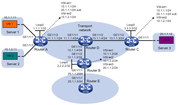
Network requirements
As shown in Figure 14:
· Configure VXLAN 10, VXLAN 20, and VXLAN 30 as unicast-mode VXLANs on Router A, Router B, and Router C to provide connectivity for the VMs across the network sites.
· Manually establish VXLAN tunnels and assign the tunnels to the VXLANs.
· Configure distributed VXLAN IP gateways on Router A and Router C to forward traffic between the VXLANs.
· Configure Router B as a border gateway to forward traffic between the VXLANs and the WAN connected to Router E.
Configuration procedure
1. On VM 1, VM 2, and VM 3, specify 10.1.1.1, 10.1.2.1, and 20.1.1.1 as the gateway address, respectively. (Details not shown.)
2. Configure IP addresses and unicast routing settings:
# Assign IP addresses to interfaces, as shown in Figure 14. (Details not shown.)
# Configure OSPF on all transport network routers (Routers A through D). (Details not shown.)
# Configure OSPF to advertise routes to networks 10.1.1.0/24, 10.1.2.0/24, 20.1.1.0/24, and 25.1.1.0/24 on Router B and Router E. (Details not shown.)
3. Configure Router A:
# Enable L2VPN.
<RouterA> system-view
[RouterA] l2vpn enable
# Create the VSI vpna and VXLAN 10.
[RouterA] vsi vpna
[RouterA-vsi-vpna] vxlan 10
[RouterA-vsi-vpna-vxlan-10] quit
[RouterA-vsi-vpna] quit
# Create the VSI vpnb and VXLAN 20.
[RouterA] vsi vpnb
[RouterA-vsi-vpnb] vxlan 20
[RouterA-vsi-vpnb-vxlan-20] quit
[RouterA-vsi-vpnb] quit
# Create the VSI vpnc and VXLAN 30.
[RouterA] vsi vpnc
[RouterA-vsi-vpnc] vxlan 30
[RouterA-vsi-vpnc-vxlan-30] quit
[RouterA-vsi-vpnc] quit
# Assign an IP address to Loopback 0. The IP address will be used as the source IP address of the VXLAN tunnels to Router B and Router C.
[RouterA] interface loopback 0
[RouterA-Loopback0] ip address 1.1.1.1 255.255.255.255
[RouterA-Loopback0] quit
# Create a VXLAN tunnel to Router B. The tunnel interface name is Tunnel 1.
[RouterA] interface tunnel 1 mode vxlan
[RouterA-Tunnel1] source 1.1.1.1
[RouterA-Tunnel1] destination 2.2.2.2
[RouterA-Tunnel1] quit
# Create a VXLAN tunnel to Router C. The tunnel interface name is Tunnel 2.
[RouterA] interface tunnel 2 mode vxlan
[RouterA-Tunnel2] source 1.1.1.1
[RouterA-Tunnel2] destination 3.3.3.3
[RouterA-Tunnel2] quit
# Assign Tunnel 1 and Tunnel 2 to VXLAN 10.
[RouterA] vsi vpna
[RouterA-vsi-vpna] vxlan 10
[RouterA-vsi-vpna-vxlan-10] tunnel 1
[RouterA-vsi-vpna-vxlan-10] tunnel 2
[RouterA-vsi-vpna-vxlan-10] quit
[RouterA-vsi-vpna] quit
# Assign Tunnel 1 and Tunnel 2 to VXLAN 20.
[RouterA] vsi vpnb
[RouterA-vsi-vpnb] vxlan 20
[RouterA-vsi-vpnb-vxlan-20] tunnel 1
[RouterA-vsi-vpnb-vxlan-20] tunnel 2
[RouterA-vsi-vpnb-vxlan-20] quit
[RouterA-vsi-vpnb] quit
# Assign Tunnel 2 to VXLAN 30.
[RouterA] vsi vpnc
[RouterA-vsi-vpnc] vxlan 30
[RouterA-vsi-vpnc-vxlan-30] tunnel 2
[RouterA-vsi-vpnc-vxlan-30] quit
[RouterA-vsi-vpnc] quit
# Map GigabitEthernet 1/1/1 to the VSI vpna.
[RouterA] interface gigabitethernet 1/1/1
[RouterA-GigabitEthernet1/1/1] xconnect vsi vpna
[RouterA-GigabitEthernet1/1/1] quit
# Map GigabitEthernet 1/1/3 to the VSI vpnb.
[RouterA] interface gigabitethernet 1/1/3
[RouterA-GigabitEthernet1/1/3] xconnect vsi vpnb
[RouterA-GigabitEthernet1/1/3] quit
# Create VSI-interface 1 and assign the interface an IP address and a MAC address. The IP address will be used as the gateway address for VXLAN 10.
[RouterA] interface vsi-interface 1
[RouterA-Vsi-interface1] ip address 10.1.1.1 255.255.255.0
[RouterA-Vsi-interface1] mac-address 1-1-1
# Specify VSI-interface 1 as a distributed gateway and enable local proxy ARP on the interface.
[RouterA-Vsi-interface1] distributed-gateway local
[RouterA-Vsi-interface1] local-proxy-arp enable
[RouterA-Vsi-interface1] quit
# Create VSI-interface 2 and assign the interface an IP address and a MAC address. The IP address will be used as the gateway address for VXLAN 20.
[RouterA] interface vsi-interface 2
[RouterA-Vsi-interface2] ip address 10.1.2.1 255.255.255.0
[RouterA-Vsi-interface2] mac-address 2-2-2
# Specify VSI-interface 2 as a distributed gateway and enable local proxy ARP on the interface.
[RouterA-Vsi-interface2] distributed-gateway local
[RouterA-Vsi-interface2] local-proxy-arp enable
[RouterA-Vsi-interface2] quit
# Specify VSI-interface 1 as the gateway interface for the VSI vpna. Assign subnet 10.1.1.0/24 to the VSI.
[RouterA] vsi vpna
[RouterA-vsi-vpna] gateway vsi-interface 1
[RouterA-vsi-vpna] gateway subnet 10.1.1.0 0.0.0.255
[RouterA-vsi-vpna] quit
# Specify VSI-interface 2 as the gateway interface for the VSI vpnb. Assign subnet 10.1.2.0/24 to the VSI.
[RouterA] vsi vpnb
[RouterA-vsi-vpnb] gateway vsi-interface 2
[RouterA-vsi-vpnb] gateway subnet 10.1.2.0 0.0.0.255
[RouterA-vsi-vpnb] quit
# Assign a secondary IP address to VSI-interface 1. The IP address will be used as the gateway address for VXLAN 30.
[RouterA] interface vsi-interface 1
[RouterA-Vsi-interface1] ip address 20.1.1.1 255.255.255.0 sub
[RouterA-Vsi-interface1] quit
# Specify VSI-interface 1 as the gateway interface for the VSI vpnc. Assign subnet 20.1.1.0/24 to the VSI.
[RouterA] vsi vpnc
[RouterA-vsi-vpnc] gateway vsi-interface 1
[RouterA-vsi-vpnc] gateway subnet 20.1.1.0 0.0.0.255
[RouterA-vsi-vpnc] quit
# Configure a routing policy for VXLAN 10. Set the policy name to vxlan10, and set the default next hop to 10.1.1.2 (VSI-interface 1 on Router B).
[RouterA] acl advanced 3000
[RouterA-acl-ipv4-adv-3000] rule 0 permit ip
[RouterA-acl-ipv4-adv-3000] quit
[RouterA] policy-based-route vxlan10 permit node 5
[RouterA-pbr-vxlan10-5] if-match acl 3000
[RouterA-pbr-vxlan10-5] apply default-next-hop 10.1.1.2
[RouterA-pbr-vxlan10-5] quit
# Configure a routing policy for VXLAN 20. Set the policy name to vxlan20, and set the default next hop to 10.1.2.2 (VSI-interface 2 on Router B).
[RouterA] policy-based-route vxlan20 permit node 5
[RouterA-pbr-vxlan20-5] if-match acl 3000
[RouterA-pbr-vxlan20-5] apply default-next-hop 10.1.2.2
[RouterA-pbr-vxlan20-5] quit
# Apply policies vxlan10 and vxlan20 to VSI-interface 1 and VSI-interface 2, respectively.
[RouterA] interface vsi-interface 1
[RouterA-Vsi-interface1] ip policy-based-route vxlan10
[RouterA-Vsi-interface1] quit
[RouterA] interface vsi-interface 2
[RouterA-Vsi-interface2] ip policy-based-route vxlan20
[RouterA-Vsi-interface2] quit
4. Configure Router B:
# Enable L2VPN.
<RouterB> system-view
[RouterB] l2vpn enable
# Create the VSI vpna and VXLAN 10.
[RouterB] vsi vpna
[RouterB-vsi-vpna] vxlan 10
[RouterB-vsi-vpna-vxlan-10] quit
[RouterB-vsi-vpna] quit
# Create the VSI vpnb and VXLAN 20.
[RouterB] vsi vpnb
[RouterB-vsi-vpnb] vxlan 20
[RouterB-vsi-vpnb-vxlan-20] quit
[RouterB-vsi-vpnb] quit
# Create the VSI vpnc and VXLAN 30.
[RouterB] vsi vpnc
[RouterB-vsi-vpnc] vxlan 30
[RouterB-vsi-vpnc-vxlan-30] quit
[RouterB-vsi-vpnc] quit
# Assign an IP address to Loopback 0. The IP address will be used as the source IP address of the VXLAN tunnels to Router A and Router C.
[RouterB] interface loopback 0
[RouterB-Loopback0] ip address 2.2.2.2 255.255.255.255
[RouterB-Loopback0] quit
# Create a VXLAN tunnel to Router A. The tunnel interface name is Tunnel 2.
[RouterB] interface tunnel 2 mode vxlan
[RouterB-Tunnel2] source 2.2.2.2
[RouterB-Tunnel2] destination 1.1.1.1
[RouterB-Tunnel2] quit
# Create a VXLAN tunnel to Router C. The tunnel interface name is Tunnel 3.
[RouterB] interface tunnel 3 mode vxlan
[RouterB-Tunnel3] source 2.2.2.2
[RouterB-Tunnel3] destination 3.3.3.3
[RouterB-Tunnel3] quit
# Assign Tunnel 2 to VXLAN 10.
[RouterB] vsi vpna
[RouterB-vsi-vpna] vxlan 10
[RouterB-vsi-vpna-vxlan-10] tunnel 2
[RouterB-vsi-vpna-vxlan-10] quit
[RouterB-vsi-vpna] quit
# Assign Tunnel 2 to VXLAN 20.
[RouterB] vsi vpnb
[RouterB-vsi-vpnb] vxlan 20
[RouterB-vsi-vpnb-vxlan-20] tunnel 2
[RouterB-vsi-vpnb-vxlan-20] quit
[RouterB-vsi-vpnb] quit
# Assign Tunnel 3 to VXLAN 30.
[RouterB] vsi vpnc
[RouterB-vsi-vpnc] vxlan 30
[RouterB-vsi-vpnc-vxlan-30] tunnel 3
[RouterB-vsi-vpnc-vxlan-30] quit
[RouterB-vsi-vpnc] quit
# Create VSI-interface 1 and assign the interface an IP address.
[RouterB] interface vsi-interface 1
[RouterB-Vsi-interface1] ip address 10.1.1.2 255.255.255.0
[RouterB-Vsi-interface1] quit
# Create VSI-interface 2 and assign the interface an IP address.
[RouterB] interface vsi-interface 2
[RouterB-Vsi-interface2] ip address 10.1.2.2 255.255.255.0
[RouterB-Vsi-interface2] quit
# Create VSI-interface 3 and assign the interface an IP address.
[RouterB] interface vsi-interface 3
[RouterB-Vsi-interface3] ip address 20.1.1.2 255.255.255.0
[RouterB-Vsi-interface3] quit
# Specify VSI-interface 1 as the gateway interface for the VSI vpna.
[RouterB] vsi vpna
[RouterB-vsi-vpna] gateway vsi-interface 1
[RouterB-vsi-vpna] quit
# Specify VSI-interface 2 as the gateway interface for the VSI vpnb.
[RouterB] vsi vpnb
[RouterB-vsi-vpnb] gateway vsi-interface 2
[RouterB-vsi-vpnb] quit
# Specify VSI-interface 3 as the gateway interface for the VSI vpnc.
[RouterB] vsi vpnc
[RouterB-vsi-vpnc] gateway vsi-interface 3
[RouterB-vsi-vpnc] quit
5. Configure Router C:
# Enable L2VPN.
<RouterC> system-view
[RouterC] l2vpn enable
# Create the VSI vpna and VXLAN 10.
[RouterC] vsi vpna
[RouterC-vsi-vpna] vxlan 10
[RouterC-vsi-vpna-vxlan-10] quit
[RouterC-vsi-vpna] quit
# Create the VSI vpnb and VXLAN 20.
[RouterC] vsi vpnb
[RouterC-vsi-vpnb] vxlan 20
[RouterC-vsi-vpnb-vxlan-20] quit
[RouterC-vsi-vpnb] quit
# Create the VSI vpnc and VXLAN 30.
[RouterC] vsi vpnc
[RouterC-vsi-vpnc] vxlan 30
[RouterC-vsi-vpnc-vxlan-30] quit
[RouterC-vsi-vpnc] quit
# Assign an IP address to Loopback 0. The IP address will be used as the source IP address of the VXLAN tunnels to Router A and Router B.
[RouterC] interface loopback 0
[RouterC-Loopback0] ip address 3.3.3.3 255.255.255.255
[RouterC-Loopback0] quit
# Create a VXLAN tunnel to Router A. The tunnel interface name is Tunnel 1.
[RouterC] interface tunnel 1 mode vxlan
[RouterC-Tunnel1] source 3.3.3.3
[RouterC-Tunnel1] destination 1.1.1.1
[RouterC-Tunnel1] quit
# Create a VXLAN tunnel to Router B. The tunnel interface name is Tunnel 3.
[RouterC] interface tunnel 3 mode vxlan
[RouterC-Tunnel3] source 3.3.3.3
[RouterC-Tunnel3] destination 2.2.2.2
[RouterC-Tunnel3] quit
# Assign Tunnel 1 and Tunnel 3 to VXLAN 10.
[RouterC] vsi vpna
[RouterC-vsi-vpna] vxlan 10
[RouterC-vsi-vpna-vxlan-10] tunnel 1
[RouterC-vsi-vpna-vxlan-10] tunnel 3
[RouterC-vsi-vpna-vxlan-10] quit
[RouterC-vsi-vpna] quit
# Assign Tunnel 1 and Tunnel 3 to VXLAN 20.
[RouterC] vsi vpnb
[RouterC-vsi-vpnb] vxlan 20
[RouterC-vsi-vpnb-vxlan-20] tunnel 1
[RouterC-vsi-vpnb-vxlan-20] tunnel 3
[RouterC-vsi-vpnb-vxlan-20] quit
[RouterC-vsi-vpnb] quit
# Assign Tunnel 1 and Tunnel 3 to VXLAN 30.
[RouterC] vsi vpnc
[RouterC-vsi-vpnc] vxlan 30
[RouterC-vsi-vpnc-vxlan-30] tunnel 1
[RouterC-vsi-vpnc-vxlan-30] tunnel 3
[RouterC-vsi-vpnc-vxlan-30] quit
[RouterC-vsi-vpnc] quit
# Map GigabitEthernet 1/1/1 to the VSI vpnc.
[RouterC] interface gigabitethernet 1/1/1
[RouterC-GigabitEthernet1/1/1] xconnect vsi vpnc
[RouterC-GigabitEthernet1/1/1] quit
# Create VSI-interface 1 and assign the interface an IP address and a MAC address. The IP address will be used as the gateway address for VXLAN 10.
[RouterC] interface vsi-interface 1
[RouterC-Vsi-interface1] ip address 10.1.1.1 255.255.255.0
[RouterC-Vsi-interface1] mac-address 1-1-1
# Specify VSI-interface 1 as a distributed gateway and enable local proxy ARP on the interface.
[RouterC-Vsi-interface1] distributed-gateway local
[RouterC-Vsi-interface1] local-proxy-arp enable
[RouterC-Vsi-interface1] quit
# Create VSI-interface 2 and assign the interface an IP address and a MAC address. The IP address will be used as the gateway address for VXLAN 20.
[RouterC] interface vsi-interface 2
[RouterC-Vsi-interface2] ip address 10.1.2.1 255.255.255.0
[RouterC-Vsi-interface2] mac-address 2-2-2
# Specify VSI-interface 2 as a distributed gateway and enable local proxy ARP on the interface.
[RouterC-Vsi-interface2] distributed-gateway local
[RouterC-Vsi-interface2] local-proxy-arp enable
[RouterC-Vsi-interface2] quit
# Specify VSI-interface 1 as the gateway interface for the VSI vpna. Assign subnet 10.1.1.0/24 to the VSI.
[RouterC] vsi vpna
[RouterC-vsi-vpna] gateway vsi-interface 1
[RouterC-vsi-vpna] gateway subnet 10.1.1.0 0.0.0.255
[RouterC-vsi-vpna] quit
# Specify VSI-interface 2 as the gateway interface for the VSI vpnb.
[RouterC] vsi vpnb
[RouterC-vsi-vpnb] gateway vsi-interface 2
[RouterC-vsi-vpnb] quit
# Assign a secondary IP address to VSI-interface 1. The IP address will be used as the gateway address for VXLAN 30.
[RouterC] interface vsi-interface 1
[RouterC-Vsi-interface1] ip address 20.1.1.1 255.255.255.0 sub
[RouterC-Vsi-interface1] quit
# Specify VSI-interface 1 as the gateway interface for the VSI vpnc. Assign subnet 20.1.1.0/24 to the VSI.
[RouterC] vsi vpnc
[RouterC-vsi-vpnc] gateway vsi-interface 1
[RouterC-vsi-vpnc] gateway subnet 20.1.1.0 0.0.0.255
[RouterC-vsi-vpnc] quit
# Configure a routing policy for the VXLANs. Set the policy name to vxlan, and set the default next hop to 20.1.1.2 (VSI-interface 1 on Router B).
[RouterC] acl advanced 3000
[RouterC-acl-ipv4-adv-3000] rule 0 permit ip
[RouterC-acl-ipv4-adv-3000] quit
[RouterC] policy-based-route vxlan permit node 5
[RouterC-pbr-vxlan-5] if-match acl 3000
[RouterC-pbr-vxlan-5] apply default-next-hop 20.1.1.2
[RouterC-pbr-vxlan-5] quit
# Apply the policy vxlan to VSI-interface 1.
[RouterC] interface Vsi-interface1
[RouterC-Vsi-interface1] ip policy-based-route vxlan
[RouterC-Vsi-interface1] quit
Verifying the configuration
1. Verify the distributed VXLAN IP gateway settings on Router A:
# Verify that the VXLAN tunnel interfaces are up on Router A.
[RouterA] display interface tunnel 2
Tunnel2
Current state: UP
Line protocol state: UP
Description: Tunnel2 Interface
Bandwidth: 64kbps
Maximum transmission unit: 64000
Internet protocol processing: Disabled
Output queue - Urgent queuing: Size/Length/Discards 0/100/0
Output queue - Protocol queuing: Size/Length/Discards 0/500/0
Output queue - FIFO queuing: Size/Length/Discards 0/75/0
Last clearing of counters: Never
Tunnel source 1.1.1.1, destination 3.3.3.3
Tunnel protocol/transport UDP_VXLAN/IP
Last 300 seconds input rate: 0 bytes/sec, 0 bits/sec, 0 packets/sec
Last 300 seconds output rate: 0 bytes/sec, 0 bits/sec, 0 packets/sec
Input: 0 packets, 0 bytes, 0 drops
Output: 0 packets, 0 bytes, 0 drops
# Verify that VSI-interface 1 is up.
[RouterA] display interface vsi-interface 1
Vsi-interface1
Current state: UP
Line protocol state: UP
Description: Vsi-interface1 Interface
Bandwidth: 1000000kbps
Maximum transmission unit: 1500
Internet address: 10.1.1.1/24 (primary)
IP packet frame type: Ethernet II, hardware address: 0001-0001-0001
IPv6 packet frame type: Ethernet II, hardware address: 0001-0001-0001
Physical: Unknown, baudrate: 1000000 kbps
Last clearing of counters: Never
Last 300 seconds input rate: 0 bytes/sec, 0 bits/sec, 0 packets/sec
Last 300 seconds output rate: 0 bytes/sec, 0 bits/sec, 0 packets/sec
Input: 0 packets, 0 bytes, 0 drops
Output: 0 packets, 0 bytes, 0 drops
# Verify that the VXLAN tunnels have been assigned to VXLAN 10, and VSI-interface 1 is the gateway interface for the VSI vpna.
[RouterA] display l2vpn vsi name vpna verbose
VSI Name: vpna
VSI Index : 0
VSI State : Up
MTU : 1500
Bandwidth : -
Broadcast Restrain : 5120 kbps
Multicast Restrain : -
Unknown Unicast Restrain: 5120 kbps
MAC Learning : Enabled
MAC Table Limit : Unlimited
MAC Learning rate : -
Drop Unknown : -
Flooding : Enabled
Gateway interface : VSI-interface 1
VXLAN ID : 10
Tunnels:
Tunnel Name Link ID State Type Flood proxy
Tunnel1 0x5000001 Up Manual Disabled
Tunnel2 0x5000002 Up Manual Disabled
ACs:
AC Link ID State
GE1/1/1 0 Up
# Verify that Router A has created ARP entries for the VMs.
[RouterA] display arp
Type: S-Static D-Dynamic O-Openflow M-Multiport I-Invalid
IP address MAC address SVID Interface Aging Type
11.1.1.4 000c-29c1-5e46 -- GE1/1/2 19 D
10.1.1.2 0003-0000-0000 -- Vsi1 20 D
10.1.1.11 0cda-41b5-cf09 -- Vsi1 20 D
10.1.2.2 0004-0000-0000 -- Vsi2 20 D
10.1.2.11 0cda-41b5-cf89 -- Vsi2 20 D
20.1.1.12 0000-fc00-0b01 -- Vsi1 19 D
2. Verify the configuration on the border gateway Router B:
# Verify that the VXLAN tunnel interfaces are up on Router B.
[RouterB] display interface tunnel 2
Tunnel2
Current state: UP
Line protocol state: UP
Description: Tunnel2 Interface
Bandwidth: 64kbps
Maximum transmission unit: 64000
Internet protocol processing: Disabled
Output queue - Urgent queuing: Size/Length/Discards 0/100/0
Output queue - Protocol queuing: Size/Length/Discards 0/500/0
Output queue - FIFO queuing: Size/Length/Discards 0/75/0
Last clearing of counters: Never
Tunnel source 2.2.2.2, destination 1.1.1.1
Tunnel protocol/transport UDP_VXLAN/IP
Last 300 seconds input rate: 0 bytes/sec, 0 bits/sec, 0 packets/sec
Last 300 seconds output rate: 0 bytes/sec, 0 bits/sec, 0 packets/sec
Input: 0 packets, 0 bytes, 0 drops
Output: 0 packets, 0 bytes, 0 drops
# Verify that VSI-interface 1 is up.
[RouterB] display interface vsi-interface 1
Vsi-interface1
Current state: UP
Line protocol state: UP
Description: Vsi-interface1 Interface
Bandwidth: 1000000kbps
Maximum transmission unit: 1500
Internet address: 10.1.1.2/24 (primary)
IP packet frame type: Ethernet II, hardware address: 0011-2200-0102
IPv6 packet frame type: Ethernet II, hardware address: 0011-2200-0102
Physical: Unknown, baudrate: 1000000 kbps
Last clearing of counters: Never
Last 300 seconds input rate: 0 bytes/sec, 0 bits/sec, 0 packets/sec
Last 300 seconds output rate: 0 bytes/sec, 0 bits/sec, 0 packets/sec
Input: 0 packets, 0 bytes, 0 drops
Output: 0 packets, 0 bytes, 0 drops
# Verify that the VXLAN tunnels have been assigned to VXLAN 10, and VSI-interface 1 is the gateway interface for the VSI vpna.
[RouterB] display l2vpn vsi name vpna verbose
VSI Name: vpna
VSI Index : 0
VSI State : Up
MTU : 1500
Bandwidth : -
Broadcast Restrain : 5120 kbps
Multicast Restrain : -
Unknown Unicast Restrain: 5120 kbps
MAC Learning : Enabled
MAC Table Limit : Unlimited
MAC Learning rate : -
Drop Unknown : -
Flooding : Enabled
Gateway interface : VSI-interface 1
VXLAN ID : 10
Tunnels:
Tunnel Name Link ID State Type Flood proxy
Tunnel1 0x5000001 Up Manual Disabled
Tunnel2 0x5000002 Up Manual Disabled
# Verify that Router B has created ARP entries for the VMs.
[RouterB] display arp
Type: S-Static D-Dynamic O-Openflow M-Multiport I-Invalid
IP address MAC address SVID Interface Aging Type
12.1.1.4 0000-fc00-00ab -- GE1/1/2 14 D
25.1.1.5 4431-9234-24bb -- GE1/1/1 17 D
10.1.1.1 0000-fc00-00ab -- Vsi1 17 D
10.1.1.11 0000-fc00-00ab -- Vsi1 20 D
10.1.2.1 0000-fc00-00bc -- Vsi2 17 D
10.1.1.11 0000-fc00-00bc -- Vsi2 20 D
20.1.1.1 0000-fc00-00aa -- Vsi3 17 D
20.1.1.12 0000-fc00-00aa -- Vsi3 20 D
# Verify that Router B has created FIB entries for the VMs.
[RouterB] display fib 10.1.1.11
Destination count: 1 FIB entry count: 1
Flag:
U:Useable G:Gateway H:Host B:Blackhole D:Dynamic S:Static
R:Relay F:FRR
Destination/Mask Nexthop Flag OutInterface/Token Label
10.1.1.11/32 10.1.1.11 UH Vsi1 Null
[RouterB] display fib 20.1.1.12
Destination count: 1 FIB entry count: 1
Flag:
U:Useable G:Gateway H:Host B:Blackhole D:Dynamic S:Static
R:Relay F:FRR
Destination/Mask Nexthop Flag OutInterface/Token Label
20.1.1.12/32 20.1.1.12 UH Vsi1 Null
3. Verify that the network connectivity for VMs meets the requirements:
# Verify that VM 1, VM 2, and VM 3 can ping each other. (Details not shown.)
# Verify that VM 1, VM 2, and VM 3 can ping GigabitEthernet 1/1/1 (25.1.1.5) on Router E for WAN access. (Details not shown.)
