Country / Region
- Products and Solutions
- Industry Solutions
- Services
- Support
- Training & Certification
- Partners
- About Us
- Contact Sales
- Become a Partner
-
 Login
Login
Country / Region
PVLAN Technology White Paper
Copyright © 2018 New H3C Technologies Co., Ltd. All rights reserved. No part of this manual may be reproduced or transmitted in any form or by any means without prior written consent of New H3C Technologies Co., Ltd. The information in this document is subject to change without notice. |
|
Overview
Technical background
Fast Ethernet development requires Layer 2 access user isolation for security and accounting purposes. To implement Layer 2 access user isolation, you can assign VLANs on a per user basis. As shown in Figure 1, six VLANs are used on Device A to isolate access users.
Figure 1 VLAN assignment on a per user basis
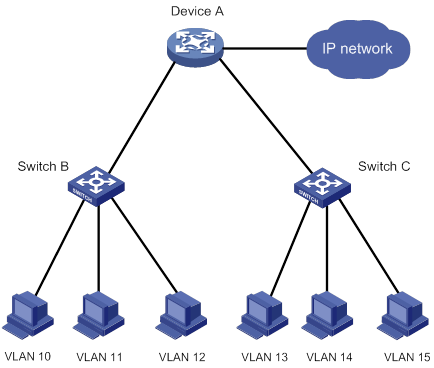
VLAN assignment on a per user basis has the following drawbacks:
Because one VLAN occupies IP addresses of a subnet, VLAN assignment on a per user basis wastes both VLAN and IP address resources.
On switching devices, VLANs use VLAN interfaces to implement Layer 3 communication, which requires a large number of IP addresses.
In accordance with the IEEE 802.1Q standard, a maximum of 4094 VLANs are available on a device. This number is far from enough for a core-layer device.
To resolve these problems, the private VLAN (PVLAN) technology was introduced to isolate access users.
Benefits
VLAN and IP address saving
PVLAN uses a two-tier structure that includes the upstream primary VLAN and downstream secondary VLANs. The upstream device is aware of only the primary VLAN. VLAN resources are saved on the upstream device.
PVLAN supports Layer 3 domains. Secondary VLANs in the Layer 3 domain of their primary VLAN use the primary VLAN interface as the gateway for Layer 3 communication. IP addresses are saved.
Enhanced security
Ports are isolated at Layer 2 in an isolated secondary VLAN, which enhances security.
High performance
MAC address synchronization enables the device to efficiently get MAC address entries for packet forwarding. Broadcast packets in the PVLAN Layer 3 domain are processed in the primary VLAN through chips, which ensures high forwarding performance.
PVLAN implementation
Concepts
PVLAN—Short for the PVLAN technology. It also refers to a set of VLANs that include a primary VLAN and secondary VLANs associated with the primary VLAN.
Primary VLAN—VLAN that is visible only to the upstream device.
Secondary VLAN—VLAN to which users belong. It has the following types:
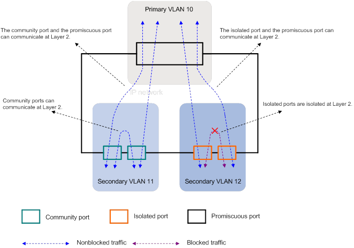
Community VLAN—VLAN whose downstream ports (called community ports, as shown in Figure 2) can communicate with each other. Secondary VLANs are community VLANs by default.
Isolated VLAN—VLAN that is configured with port isolation. Downstream ports of the VLAN (called isolated ports) are isolated from each other, as shown in Figure 2.
Host port—Downstream port connected to a user for terminal access. The PVID of a host port must be a secondary VLAN, so the port can forward packets from the primary VLAN.
For a downstream port to permit only one secondary VLAN, configure the port as a host port. The port can then transmit packets from the secondary VLAN without VLAN tags.
Trunk secondary port—Downstream port connected to the downstream device. The port replaces the primary VLAN ID of outgoing packets with a secondary VLAN ID.
A trunk secondary port can join only one of the secondary VLANs that are associated with a primary VLAN. The port can join multiple secondary VLANs that are associated with different primary VLANs.
For a downstream port to permit multiple secondary VLANs, configure the port as a trunk secondary port. The port can then transmit packets from these secondary VLANs with VLAN tags.
Promiscuous port—Upstream port connected to the upstream device. Make sure the PVID of a promiscuous port is a primary VLAN, so the port can forward packets from secondary VLANs associated with the primary VLAN.
For an upstream port to permit only one primary VLAN, configure the port as a promiscuous port. The port can then transmit packets from the primary VLAN without VLAN tags.
Trunk promiscuous port—Upstream port connected to the upstream device. The port replaces secondary VLAN IDs of outgoing packets with their respective associated primary VLAN IDs.
For an upstream port to permit multiple primary VLANs, configure the port as a trunk promiscuous port. The port can then transmit packets from these primary VLANs with VLAN tags.
PVLAN Layer 3 domain—PVLAN domain associated with the primary VLAN. Secondary VLANs that are assigned to the domain can communicate at Layer 3 and use the primary VLAN interface as the gateway. To create a PVLAN Layer 3 domain and assign secondary VLANs to the domain, perform the following tasks:
a. Create the VLAN interface for the primary VLAN and assign an IP address to it.
b. Specify secondary VLANs for Layer 3 communication in primary VLAN interface view.
c. Enable local proxy ARP or ND on the primary VLAN interface.
Mechanism
PVLAN processes packets from secondary VLANs and primary VLANs as follows:
For packets from secondary VLANs, the upstream port removes the VLAN tags or replaces them with associated primary VLAN tags before sending the packets to the upstream device.
For packets from primary VLANs, the downstream port removes the VLAN tags or replaces them with associated secondary VLAN tags before sending the packets to users.
Whether VLAN tags of outgoing packets on downstream and upstream ports are removed or replaced depends on the port configuration. Primary VLANs are invisible to users, and secondary VLANs are invisible to the upstream device.
PVLAN provides configuration synchronization and MAC address synchronization to simplify user configuration and improve packet forwarding efficiency.
PVLAN uses the PVLAN Layer 3 domain to implement Layer 3 communication between secondary VLANs.
Port communication and isolation
Port communication and isolation on a single device
As shown in Figure 2:
The promiscuous port can communicate with both community ports and isolated ports at Layer 2.
Community ports can communicate at Layer 2.
Isolated ports are isolated at Layer 2.
A trunk promiscuous port also can communicate with both community ports and isolated ports at Layer 2.
Figure 2 Port communication and isolation on a single device
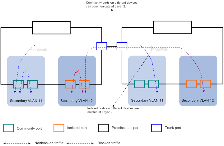
Port communication and isolation across devices
As shown in Figure 3:
Community ports on different devices can communicate at Layer 2.
Isolated ports on different devices cannot communicate at Layer 2. The isolation is implemented by using the trunk or hybrid ports to forward packets from the isolated VLAN with the isolated VLAN tag.
Figure 3 Port communication and isolation across devices
PVLAN configuration synchronization
PVLAN configuration synchronization simplifies user configuration, particularly in a network with a large number of secondary VLANs.
To trigger PVLAN configuration synchronization, perform the following tasks in any order:
Specify a primary VLAN.
Associate the primary VLAN with secondary VLANs.
Configure downstream ports as host or trunk secondary ports.
Configure upstream ports as promiscuous or trunk promiscuous ports.
PVLAN configuration synchronization changes the following port attributes:
Port link type—Access ports are converted to hybrid ports. The port link types of hybrid and trunk ports do not change.
VLAN member status—If a port is a tagged or untagged member of some VLANs, the port's member attribute remains in these VLANs. The port joins other VLANs according to the following rules:
If the port is a host port, it joins the primary VLAN as an untagged member.
If the port is a trunk secondary port, it joins secondary VLANs and their associated primary VLANs as a tagged member.
If the port is a promiscuous port, it joins secondary VLANs as an untagged member.
If the port is a trunk promiscuous port, it joins primary VLANs and their associated secondary VLANs as a tagged member.
As shown in Figure 4, port attributes change (see Table 1 and Table 2) after you perform the following tasks:
On Device A:
Configure VLAN 10 as a primary VLAN, and associate primary VLAN 10 with secondary VLANs 201 and 301.
Configure GigabitEthernet 1/0/1 as a promiscuous port of primary VLAN 10.
Configure GigabitEthernet 1/0/2 as a host port of secondary VLAN 301.
Configure GigabitEthernet 1/0/3 as a host port of secondary VLAN 201.
On Device B:
Configure VLAN 10 as a primary VLAN, and associate primary VLAN 10 with secondary VLAN 201.
Configure VLAN 20 as a primary VLAN, and associate primary VLAN 20 with secondary VLAN 401.
Configure GigabitEthernet 1/0/1 as a trunk promiscuous port of primary VLANs 10 and 20.
Configure GigabitEthernet 1/0/2 as a host port of VLAN 201.
Configure GigabitEthernet 1/0/3 as a trunk secondary port of secondary VLANs 201 and 401.
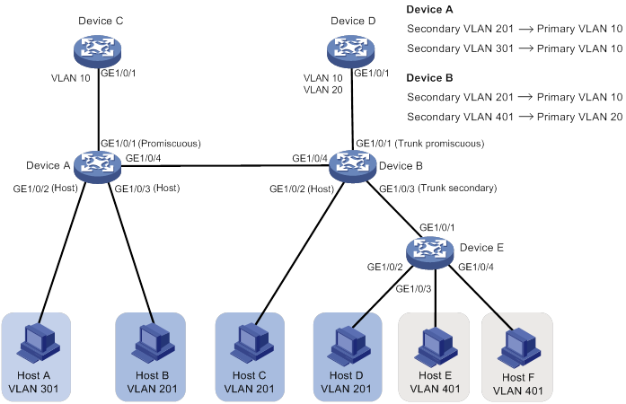
Table 1 Port attributes before configuration synchronization
Device | Port | Port link type | PVID | Permitted VLANs |
Device A | GigabitEthernet 1/0/1 | Access | 10 | VLAN 10 |
Device A | GigabitEthernet 1/0/2 | Access | 301 | VLAN 301 |
Device A | GigabitEthernet 1/0/3 | Access | 201 | VLAN 201 |
Device B | GigabitEthernet 1/0/1 | Access | 1 | VLAN 1 |
Device B | GigabitEthernet 1/0/2 | Access | 201 | VLAN 201 |
Device B | GigabitEthernet 1/0/3 | Access | 1 | VLAN 1 |
Table 2 Port attributes after configuration synchronization
Device | Port | Port link type | Port mode | PVID | Permitted VLANs |
Device A | GigabitEthernet 1/0/1 | Hybrid | Promiscuous port of VLAN 10 | 10 | VLANs 10, 201, and 301 |
Device A | GigabitEthernet 1/0/2 | Hybrid | Host | 301 | VLANs 10 and 301 |
Device A | GigabitEthernet 1/0/3 | Hybrid | Host | 201 | VLANs 10 and 201 |
Device B | GigabitEthernet 1/0/1 | Hybrid | Trunk promiscuous port of VLANs 10 and 20 | 1 | VLANs 1, 10, 201, 20, and 401 |
Device B | GigabitEthernet 1/0/2 | Hybrid | Host | 201 | VLANs 10 and 201 |
Device B | GigabitEthernet 1/0/3 | Hybrid | Trunk secondary port of VLANs 201 and 401 | 1 | VLANs 1, 10, 201, 20, and 401 |
MAC address synchronization
Without MAC address synchronization, the device performs typical MAC address learning. As shown in Figure 5, Device A maintains the MAC address table described in Table 3. When a packet from Device C to Host A arrives, Device A performs the following operations:
Adds VLAN tag 10 (PVID of GigabitEthernet 1/0/1) to the packet.
Searches the MAC address table for the entry that has the MAC address of Host A and VLAN 10.
Floods the packet in VLAN 10 because no matching entry is found. The packet is sent out of GigabitEthernet 1/0/2 and GigabitEthernet 1/0/3.
Figure 5 Packet forwarding without MAC address synchronization
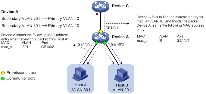
Table 3 MAC address table on Device A without MAC address synchronization
MAC | VLAN | Port |
mac_c | 10 | GigabitEthernet 1/0/1 |
mac_a | 301 | GigabitEthernet 1/0/2 |
mac_b | 201 | GigabitEthernet 1/0/3 |
In this example, downstream and upstream packets are flooded to reach the destination until Device A learns MAC address entries for forwarding packets from hosts and Device C. Packet flooding is bandwidth-consuming, particularly when secondary VLANs and the primary VLAN has many ports. In addition, security risks exist because the flooded packets might be intercepted or snooped.
To resolve the problem, PVLAN uses MAC address synchronization. MAC address synchronization synchronizes MAC address entries as follows:
Synchronizes MAC address entries dynamically learned on downstream ports in secondary VLANs to the primary VLAN.
Synchronizes MAC address entries dynamically learned on the upstream port in the primary VLAN to secondary VLANs.
Through MAC address synchronization, Device A obtains the MAC address table described in Table 4. When receiving packets from Device C, Device A unicasts them to Host A.
Figure 6 Packet forwarding after MAC address synchronization

Table 4 MAC address table on Device A after MAC address synchronization
MAC | VLAN | Port |
mac_c | 10 | GigabitEthernet 1/0/1 |
mac_c | 201 | GigabitEthernet 1/0/1 |
mac_c | 301 | GigabitEthernet 1/0/1 |
mac_a | 301 | GigabitEthernet 1/0/2 |
mac_a | 10 | GigabitEthernet 1/0/2 |
mac_b | 201 | GigabitEthernet 1/0/3 |
mac_b | 10 | GigabitEthernet 1/0/3 |
This example uses community and promiscuous ports. MAC address synchronization applies the same process to the synchronization between the following ports:
Community and trunk promiscuous ports.
Isolated and promiscuous ports (except that ports in the same isolated VLAN are isolated at Layer 2).
Isolated and trunk promiscuous ports (except that ports in the same isolated VLAN are isolated at Layer 2).
All devices support MAC address synchronization from secondary VLANs to the primary VLAN. Support for MAC address synchronization from the primary VLAN to secondary VLANs varies by device model. The reasons are as follows:
Forwarding performance degradation—If a primary VLAN is associated with many secondary VLANs, the MAC address table of the device will be populated with excessive MAC address entries. This degrades the forwarding performance of the device.
Sparse upstream traffic—The device processes much more downstream packets than upstream packets. Downstream packets require unicast. Upstream packets can be flooded to reach the destination.
PVLAN Layer 3 domain
In a PVLAN Layer 3 domain, secondary VLANs communicate at Layer 3 through the primary VLAN interface. You cannot create VLAN interfaces for these secondary VLANs. You can configure VLAN interfaces for secondary VLANs that are not in the PVLAN Layer 3 domain for more flexible network building.
To implement Layer 3 communication between secondary VLANs that are in the same PVLAN Layer 3 domain, enable local proxy ARP or ND on the primary VLAN interface.
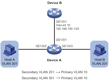
For a device that supports PVLAN Layer 3 domains, enable local proxy ARP or ND on the primary VLAN interface on the device, as shown in Figure 7.
Figure 7 Enabling local proxy ARP or ND locally
For a device that does not support PVLAN Layer 3 domains, enable local proxy ARP or ND on the primary VLAN interface configured on the upstream device, as shown in Figure 8.
Figure 8 Enabling local proxy ARP or ND on the upstream device
Restrictions
When you configure PVLAN, follow these restrictions and guidelines:
VLAN 1 (system default VLAN) does not support the PVLAN configuration.
The PVLAN configuration on a port does not overwrite the PVID and VLAN member attribute of the port. If you have configured the PVID and VLAN member attribute for a port before you configure PVLAN, make sure the existing port configuration is correct.
The removal of PVLAN configuration from a secondary VLAN or primary VLAN does not affect the PVLAN configuration of their associated primary VLAN or secondary VLANs.
When PVLAN is used with Layer 2 multicast, multicast protocols that are configured for the primary VLAN will be synchronized to its associated secondary VLANs. H3C recommends not configuring Layer 2 multicast protocols for secondary VLANs.
When a PVLAN device is connected to PVST devices, the following requirements must be met:
The port that connects to the upstream PVST device must be a trunk promiscuous port.
Ports that connect to downstream PVST devices must be trunk secondary ports.
The link type must be trunk for the ports that connect the PVLAN device to PVST devices.
Application scenarios
Layer 2 application
Because PVLAN saves VLAN resources and supports secondary VLAN isolation, you can use PVLAN to build a Layer 2 network by using a few VLANs.
As shown in Figure 9, configure PVLAN to meet the following requirements:
All hosts can access the server.
Host A and Host D are isolated in secondary VLAN 301.
Hosts of other secondary VLANs can communicate at Layer 2 within their VLANs.
Figure 9 Layer 2 PVLAN network
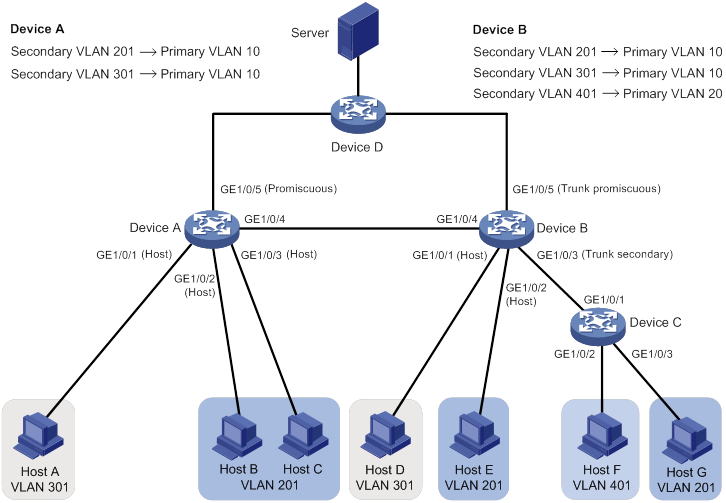
To meet the network requirements, perform the following tasks:
On Device A:
Configure VLAN 10 as a primary VLAN and VLAN 301 as an isolated VLAN.
Associate primary VLAN 10 with secondary VLANs 301 and 201.
Configure GigabitEthernet 1/0/1 as a host port of isolated VLAN 301.
Configure GigabitEthernet 1/0/2 and GigabitEthernet 1/0/3 as host ports of community VLAN 201.
Configure GigabitEthernet 1/0/4 as a trunk port, and assign the port to primary VLAN 10, isolated VLAN 301, and community VLAN 201.
Configure GigabitEthernet 1/0/5 as a promiscuous port of primary VLAN 10.
On Device B:
Configure VLAN 10 as a primary VLAN and VLAN 301 as an isolated VLAN.
Associate primary VLAN 10 with secondary VLANs 301 and 201.
Configure VLAN 20 as a primary VLAN, and associate primary VLAN 20 with secondary VLAN 401.
Configure GigabitEthernet 1/0/1, GigabitEthernet 1/0/2, and GigabitEthernet 1/0/4 in the same way GigabitEthernet 1/0/1, GigabitEthernet 1/0/2, and GigabitEthernet 1/0/4 on Device A are configured.
Configure GigabitEthernet 1/0/3 as a trunk secondary port of secondary VLANs 201 and 401.
Configure GigabitEthernet 1/0/5 as a trunk promiscuous port of primary VLANs 10 and 20.
On Device C:
Configure GigabitEthernet 1/0/1 as a trunk port, and assign the port to VLANs 201 and 401.
Configure PVIDs of GigabitEthernet 1/0/2 and GigabitEthernet 1/0/3 as 401 and 201, respectively.
Packet processing between Host B and the server
When packets from the server to Host B arrive at Device A, Device A processes the packets as follows:
1. Tags the packets with VLAN 10 at GigabitEthernet 1/0/5.
2. Removes the VLAN tag before sending the packets out of GigabitEthernet 1/0/2.
When packets from Host B to the server arrive at Device A, Device A processes the packets as follows:
1. Tags the packets with VLAN 201 at GigabitEthernet 1/0/2.
2. Removes the VLAN tag before sending the packets out of GigabitEthernet 1/0/5.
The packets are then forwarded to the server through Device D.
Packet processing between Host A and the server
The server can receive broadcast packets tagged with VLAN 301 from Host A. Packet processing on Device A is the same as the packets transmitted between Host B and the server.
However, Host D cannot receive broadcast packets from Host A. Because GigabitEthernet 1/0/1 of Device B is a host port in isolated VLAN 301, the port cannot forward packets from Host A.
Packet processing between Host F and the server
When packets from Host F to the server arrive at Device C, Device C tags the packets with VLAN 401 at GigabitEthernet 1/0/2. Then, Device C sends the tagged packets out of GigabitEthernet 1/0/1.
When the tagged packets arrive at Device B, they are forwarded in VLAN 401. GigabitEthernet 1/0/5 replaces the tag of the packets with VLAN 20, and sends them to the server through Device D.
Layer 3 application
PVLAN Layer 3 domain can be used with DHCP or VRRP at Layer 3.
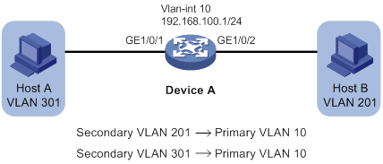
PVLAN with DHCP
As shown in Figure 10, Host A and Host B request IP address settings, DNS server address, and static route information from the DHCP server.
Figure 10 PVLAN network enabled with DHCP
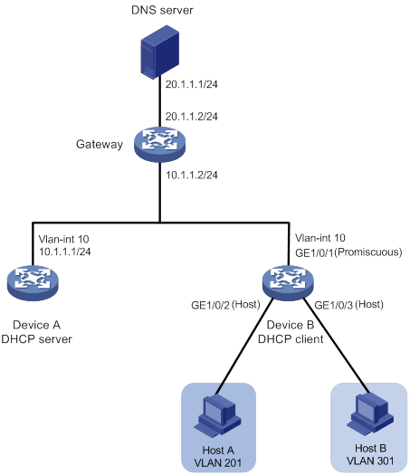
To meet the network requirements, perform the following tasks:
On Device B:
Configure VLAN 10 as a primary VLAN, and associate the primary VLAN with secondary VLANs 201 and 301.
Assign secondary VLANs 201 and 301 to the PVLAN Layer 3 domain of primary VLAN 10.
Configure GigabitEthernet 1/0/1 as a promiscuous port of VLAN 10.
Enable the DHCP client on VLAN-interface 10. Hosts A and B use this VLAN interface to obtain IP addresses.
On Device A:
Enable the DHCP server on VLAN-interface 10.
Configure a DHCP address pool to assign IP addresses and other configuration parameters to clients on subnet 10.1.1.0/24.
Specify 20.1.1.1/24 and 10.1.1.2/24 as the DNS server address and gateway address, respectively.
PVLAN with VRRP
As shown in Figure 11, Host A, Host B, and Host C require access to Host D.
Figure 11 PVLAN network enabled with VRRP
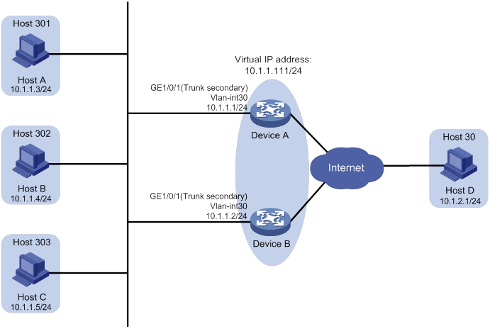
Use VRRP and PVLAN as follows:
Assign Device A and Device B to a VRRP group to ensure high availability.
When Device A operates correctly, Device A forwards packets from Host A to Host D. When Device A fails, Device B forwards packets from Host A to Host D.
When Device A recovers, Device A forwards packets from Host A to Host D.
Use the PVLAN Layer 3 domain so Device A and Device B use only one VLAN interface.
Perform the following tasks on Device A:
Configure VLAN 30 as a primary VLAN, and associate the primary VLAN with secondary VLANs 301 through 303.
Create VLAN-interface 30 and assign the IP address 10.1.1.1/24 to VLAN-interface 30.
Assign secondary VLANs 301 through 303 to the PVLAN Layer 3 domain of primary VLAN 30.
Configure GigabitEthernet 1/0/1 as a trunk secondary port of VLANs 301 through 303.
Create VRRP group 1, and assign the IP address 10.1.1.111/24 to the group.
Set the priority of Device A to 110 in VRRP group 1 to ensure that Device A acts as the master in the group.
Configure Device A to operate in preemptive mode, and set the preemption delay to 5 seconds.
Perform the following tasks on Device B:
Configure VLAN 30 as a primary VLAN, and associate the primary VLAN with secondary VLANs 301 through 303.
Create VLAN-interface 30, and assign the IP address 10.1.1.2/24 to VLAN-interface 30.
Assign secondary VLANs 301 through 303 to the PVLAN Layer 3 domain of primary VLAN 30.
Configure GigabitEthernet 1/0/1 as a trunk secondary port of VLANs 301 through 303.
Create VRRP group 1, and assign the IP address 10.1.1.111/24 to the group.
Set the priority of Device B to 100 in VRRP group 1.
Configure Device B to operate in preemptive mode, and set the preemption delay to 5 seconds.
On Host A, specify 10.1.1.111/24 as its gateway address.
PVLAN and multicast
PVLAN with Layer 2 multicast
To use PVLAN with Layer 2 multicast, configure a Layer 2 multicast protocol for the primary VLAN. PVLAN synchronizes the Layer 2 multicast configuration to the secondary VLANs associated with the primary VLAN. Multicast packets within the PVLAN, including data packets and protocol packets, are forwarded in the primary VLAN. The primary VLAN maintains multicast entries.
As shown in Figure 12, Router A acts as an IGMP querier. Host A, Host B, and Host E require multicast data from the group 224.1.1.1.
Figure 12 PVLAN network enabled with Layer 2 multicast
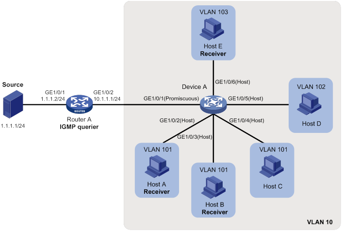
To meet the network requirements, use IGMPv2 on Router A, and perform the following tasks on Device A:
Configure VLAN 10 as a primary VLAN, and associate the primary VLAN with secondary VLANs 101, 102, and 103.
Configure GigabitEthernet 1/0/1 as a promiscuous port of primary VLAN 10.
Configure GigabitEthernet 1/0/2, GigabitEthernet 1/0/3, and GigabitEthernet 1/0/4 as host ports of secondary VLAN 101.
Configure GigabitEthernet 1/0/5 as a host port of secondary VLAN 102.
Configure GigabitEthernet 1/0/6 as a host port of secondary VLAN 103.
Enable dropping unknown multicast data.
Enable IGMP snooping. (The default IGMP snooping version is 2.)
If Host A, Host B, or Host E temporarily fails, multicast data from the group 224.1.1.1 can still be forwarded out of GigabitEthernet 1/0/2, GigabitEthernet 1/0/3, and GigabitEthernet 1/0/6. Device A drops unknown multicast data instead of flooding it in primary VLAN 10.
PVLAN with Layer 3 multicast
Use Layer 3 multicast with the PVLAN Layer 3 domain, and configure a Layer 3 multicast protocol in the primary VLAN interface. Multicast packets, including data and protocol packets, are sent to the primary VLAN interface for processing. The primary VLAN interface maintains Layer 3 multicast entries.
As shown in Figure 13, all devices are in a PIM-SM domain. Host B in stub network N1 and Host C in stub network N2 require multicast data from the group 225.1.1.0/24.
Figure 13 PVLAN network enabled with Layer 3 multicast
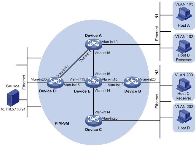
Device | Interface | Address | Device | Interface | Address |
Device A | VLAN-interface 10 | 10.110.1.1/24 | Device D | VLAN-interface 30 | 10.110.5.1/24 |
Device A | VLAN-interface 11 | 192.168.1.1/24 | Device D | VLAN-interface 11 | 192.168.1.2/24 |
Device A | VLAN-interface 16 | 192.168.9.1/24 | Device D | VLAN-interface 15 | 192.168.4.2/24 |
Device B | VLAN-interface 20 | 10.110.2.1/24 | Device E | VLAN-interface 14 | 192.168.3.2/24 |
Device B | VLAN-interface 13 | 192.168.2.1/24 | Device E | VLAN-interface 13 | 192.168.2.2/24 |
Device C | VLAN-interface 20 | 10.110.2.2/24 | Device E | VLAN-interface 15 | 192.168.4.1/24 |
Device C | VLAN-interface 14 | 192.168.3.1/24 | Device E | VLAN-interface 16 | 192.168.9.2/24 |
To meet the network requirements, perform the following tasks:
Assign IP addresses to interfaces, as shown in Table 5.
On Device A:
Configure VLAN 10 as a primary VLAN, and associate the primary VLAN with secondary VLANs 102 and 103.
Assign secondary VLANs 102 and 103 to the PVLAN Layer 3 domain of primary VLAN 10.
On Device B:
Configure VLAN 20 as a primary VLAN, and associate the primary VLAN with secondary VLANs 202 and 203.
Assign secondary VLANs 202 and 203 to the PVLAN Layer 3 domain of primary VLAN 20.
On Device C:
Configure VLAN 20 as a primary VLAN, and associate the primary VLAN with secondary VLANs 202 and VLAN 203.
Assign secondary VLANs 202 and 203 to the PVLAN Layer 3 domain of primary VLAN 20.
On Device E, configure VLAN-interface 16 as a C-BSR and a C-RP. The C-RP provides services for the multicast group 225.1.1.0/24.
On all devices, configure the static RP by specifying its IP address as the IP address of VLAN-interface 11 on Device D.
Enable IGMP on the following interfaces that are connected to stub networks:
VLAN-interface 10 on Device A.
VLAN-interface 20 on Device B.
VLAN-interface 20 on Device C.
(The default IGMP version is 2.)