Country / Region
- Products and Solutions
- Industry Solutions
- Services
- Support
- Training & Certification
- Partners
- About Us
- Contact Sales
- Become a Partner
-
 Login
Login
Country / Region
EVI Technology White Paper
Copyright © 2018 New H3C Technologies Co., Ltd. All rights reserved. No part of this manual may be reproduced or transmitted in any form or by any means without prior written consent of New H3C Technologies Co., Ltd. The information in this document is subject to change without notice. |
|
Overview
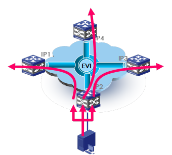
Ethernet Virtual Interconnect (EVI) is a MAC-in-IP technology that provides Layer 2 connectivity between distant Layer 2 network sites across an IP routed network. It is used for connecting geographically dispersed data centers that require Layer 2 adjacency.
Technical background
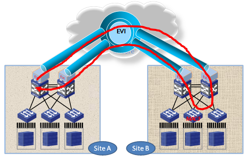
Most large enterprises have dater centers in different regions and deploy the same applications in these data centers for high availability and redundancy. Data centers are also increasingly virtualized for improving resource efficiency and application availability. Data center challenges, including transparent mobility of virtual machines and dynamic allocation and management of resources across data centers, have compelled the need for Layer 2 connectivity extension across data centers.
Figure 1 Layer 2 connectivity extension across data centers
A Layer 2 connectivity extension technology should address the following issues:
Site independence—Isolates protocol failures, such as broadcast storms, within sites. Topology changes within one site should not affect other sites.
Transport independence—Eliminates the need to deal with transport network (or Layer 3 interconnect) dependencies, has no special requirement for site location, and can work with any widely used transport network type, for example, an IP network.
High availability—Supports redundant edge devices and provides loop-free mechanisms to prevent loops for multihomed sites.
Link efficiency—Optimizes the inter-site multicast and broadcast transmission mechanism and implements load sharing on redundant links.
Site and transport transparency—Site and transport network transparent, and no special site or transport network topology requirements.
Easy management and maintenance—Easy to configure, allows easy adds and removals of sites, and introduces as little impact as possible on the site topology and transport network topology. The deployment process does not affect the ongoing services.
Benefits
EVI provides an easy-to-implement cost-effective DCI solution. It extends Layer 2 connectivity across geographically dispersed data centers over the existing transport network infrastructure. It requires deployment only on edge devices and introduces zero topology changes and configurations within sites or the transport network.
EVI implementation
This section describes the EVI implementation, including its operating mechanisms and implementation considerations.
Network topologies
As shown in Figure 2, an EVI network is an overlay network that connects site networks across an IP transport network. It has one or multiple edge devices at each site. These sites are connected through virtual links and run the EVI IS-IS protocol on their edge devices to advertise their MAC address entries to each other. EVI maintains MAC routing information on the edge devices without changing the forwarding or routing information within the sites or the transport network.
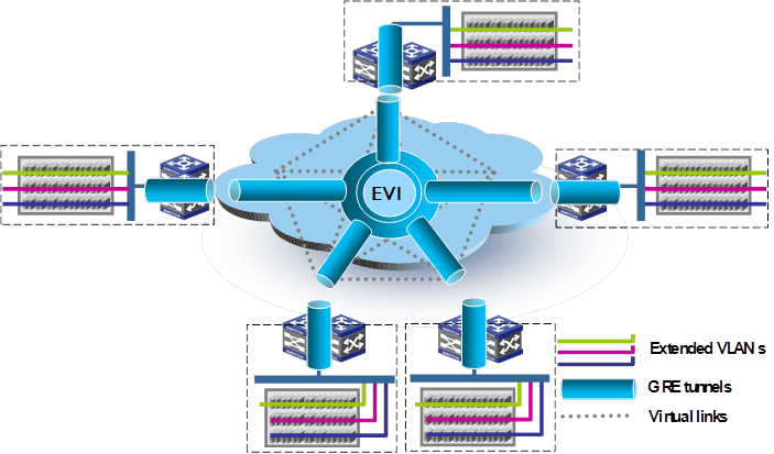
The EVI network extends VLANs across sites at the data plane, but it runs EVI IS-IS at the control plane to advertise MAC reachability information, in contrast to the conventional MAC learning at the data plane. At the control plane, EVI also runs an automatic neighbor discovery protocol to discover neighboring sites for management simplicity.
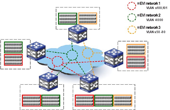
EVI supports multiple EVI networks on an edge device for different VLANs. As shown in Figure 3, one EVI network can convey multiple VLANs, but one VLAN can map to only one EVI network. Each EVI network has separate network parameters and independently forwards traffic.
Figure 3 Multiple EVI networks
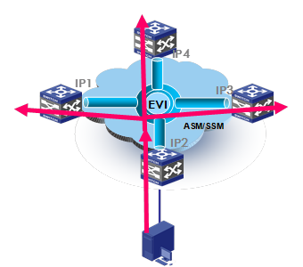
Depending on the traffic pattern, number of sites, and transport network's multicast capability, two multicast and broadcast traffic handling modes are available for an EVI network: sparse mode (SM) and dense mode (DM).
In SM mode, an edge device duplicates multicast and broadcast traffic at the headend of each virtual link and sends the traffic out in unicast packets. Typically, you use this mode if the network has few multicast applications or sites, or the transport network does not support multicast.
In DM mode, multicast and broadcast traffic is mapped to the multicast tree in the transport network and duplicated in the transport network. Typically, you use this mode if the transport network supports multicast and the number of sites is large.
To the date of this writing, H3C has supported only the SM mode.
Figure 4 shows how multicast or broadcast traffic is forwarded in these two modes.
Figure 4 Multicast/broadcast traffic forwarding models for EVI networks
Concepts
Edge device
An edge device performs typical Layer 2 learning and forwarding on the site-facing interfaces (internal interfaces) and performs tunneling and routing on the transport-facing interfaces.
EVI network ID
An edge device can belong to multiple EVI networks. Each EVI network is uniquely identified by a network ID. All edge devices in the same EVI network must use the same EVI network ID.
EVI-Connect interface
An EVI-Connect interface is a Layer 3 interface that connects an edge device to the transport network. The edge device uses the IP address of this interface as the source IP address of the EVI tunnel for an EVI network.
This interface can be a Layer 3 Ethernet interface, Layer 3 aggregate interface, VLAN interface, or Loopback interface.
Different EVI networks can share the same EVI-Connect interface.
EVI link
An EVI link is a bidirectional virtual Ethernet channel between a pair of edge devices in an EVI network. Each EVI link is uniquely identified by the IP addresses of the local and remote EVI-Connect interfaces.
EVI-Link interface
An EVI-Link interface is a virtual point-to-cloud interface for an EVI link. The interface encapsulates Layer 2 frames in IP and copies broadcast and multicast packets that must be transmitted between sites in an EVI network.
EVI tunnel
An EVI tunnel is a point-to-many automatic GRE tunnel that conveys EVI links for an EVI network. One EVI tunnel can serve only one EVI network.
EVI neighbor
All edge devices in an EVI network are EVI neighbors to one other.
ENDP
Enhanced Neighbor Discovery Protocol uses the client/server model to dynamically discover sites and edge devices, establish and maintain EVI links, and exchange network membership information in an EVI network.
ENDS
An enhanced neighbor discovery server maintains all neighbor information in an EVI network, including the client addresses and EVI network ID. An EVI network can have up to two ENDSs.
ENDC
An enhanced neighbor discovery client works with an ENDS to learn neighbor information and triggers EVI link setup between neighbors.
EVI IS-IS
EVI IS-IS establishes adjacencies and advertises MAC reachability information among edge devices at different sites in an EVI network. It also maps VLANs to redundant edge devices at a multihomed site to avoid loops and balance traffic.
EVI IS-IS runs independently of the Layer 3 routing protocols on the transport network and sites.
DED
At a multihomed site, the redundant edge devices elect a designated edge device to assign extended VLANs among them so the traffic of a VLAN always enters or leaves the site from the same edge device. This DED also sends CSNP packets to remote edge devices for LSDB synchronization.
Appointed edge forwarder
If an edge device is assigned by DED to forward and receive traffic for an extended VLAN, this edge device is the appointed edge forwarder for the extended VLAN. This extended VLAN is an "active VLAN" on the edge device.
Internal interface
Internal interfaces are site-facing Layer 2 interfaces that connect an edge device to switches or routers in the site.
Mechanisms
Control plane
Neighbor discovery
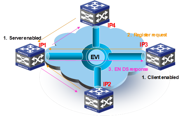
Before the edge devices in an EVI network can advertise MAC reachability information, they must run ENDP to discover one another and form adjacencies.
With ENDP, one edge device works as ENDS and all other edge devices work as ENDCs to register with the ENDS. The ENDS maintains a client database (including each client's IP address, MAC address, and neighbor entry lifetime) and propagates client information to all ENDCs.
As shown in Figure 5, an EVI network runs ENDP to discover all its edge devices and establishes adjacencies among the edge devices in the following process:
1. ENDS is enabled on one edge device and ENDC is enabled on all other edge devices.
2. The ENDCs register their IP addresses and other data with the ENDS.
3. The ENDS updates its ENDC database with received data and sends the updated database to each ENDC.
4. After receiving the register reply, the ENDCs establish an EVI link with each other for forwarding traffic.
For high availability, you can configure up to two ENDSs for an EVI network. For security, you can also enable ENDP authentication to make sure only trustworthy sites are registered.
Figure 5 EVI neighbor discovery
EVI tunnel maintenance
EVI edge devices connect to each other through EVI links over EVI tunnels.
An edge device periodically sends keepalive packets over an EVI link to detect the peer end. If no reply is received after the maximum number of keepalive attempts has been made, the edge device brings down the EVI-Link interface. The EVI-Link interface remains in Down state until the edge device receives a keepalive packet or keepalive reply from the peer end.
MAC reachability information propagation
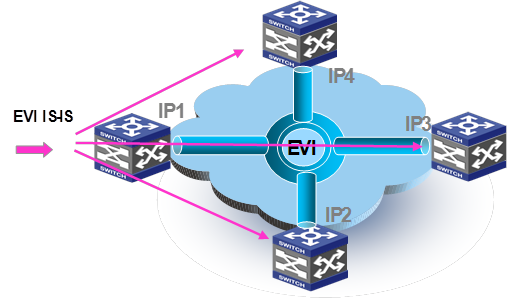
After completing neighbor discovery, the edge devices run EVI IS-IS at the control plane to establish adjacencies and advertise their MAC reachability information to each other over EVI links.
EVI IS-IS uses IS-IS Hello packets for setting up adjacencies and uses LSPs for advertising MAC reachability information.
In head-end replication mode, EVI IS-IS runs on point-to-point virtual links. An edge device sets up a point-to-point virtual link with each remote edge device, replicates EVI IS-IS packets, and sends EVI IS-IS packets in unicast IP packets over each virtual link.
Figure 6 Head-end replication method to EVI IS-IS packet transmission
In head-end replication mode, an EVI IS-IS Hello is transmitted as follows:
1. The EVI IS-IS process on an edge device generates a Hello packet.
2. The edge device creates one copy of the Hello packet for each remote edge device, encapsulates each replica, and unicasts the encapsulated Hello packets out of the data plane to the remote edge devices. The destination IP address in the IP header of each replica is the IP address of a remote edge device.
3. The transport network unicasts the Hello packets to their respective destinations.
4. The receiving edge devices decapsulate the packets, and pass the EVI IS-IS Hello packets to their respective EVI IS-IS processes at the control plane.
After establishing adjacencies, EVI IS-IS processes advertise MAC reachability information, as shown in Figure 7.
Figure 7 MAC reachability information advertisement
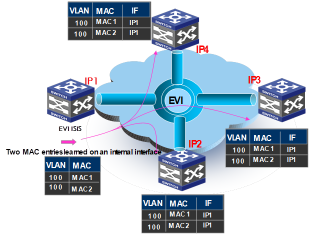
1. The edge device at site 1 (IP 1) learns new MAC addresses in VLAN 100 on its internal interface. On internal interfaces, MAC learning uses the typical data plane learning process.
2. The EVI IS-IS process on IP 1 generates an LSP update for advertising new MAC reachability information.
3. IP 1 replicates and unicasts the LSP update.
4. Each receiving edge device (IP 2, IP 3, and IP 4) decapsulates the LSP and delivers the LSP to the EVI IS-IS process at the control plane.
5. The EVI IS-IS process on each edge device adds the new MAC addresses to the MAC address table, with the outgoing interface being the EVI tunnel interface.
When an edge device removes a local MAC address from its MAC address table, its EVI IS-IS process advertises the removal in an update LSP to notify all remote edge devices to remove the MAC entry. In addition, edge devices also refresh LSPs regularly (by default, at 900-second intervals). If an LSP ages out from the EVI IS-IS LSDB on an edge device, the remote MAC addresses advertised through the LSP are removed from the MAC address table at the data plane.
Data plane
Unicast traffic
Once control plane adjacencies are established and MAC reachability information is exchanged, EVI edge devices can forward traffic to remote sites.
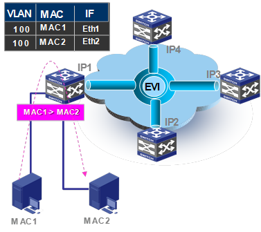
For intra-site destination-known unicast flows, an edge device performs the typical Layer 2 traffic forwarding procedure. As shown in Figure 8, when the edge device IP 1 receives a frame sent from MAC 1 to MAC 2 in a VLAN, it learns the source MAC address (MAC 1) in the VLAN on the incoming port Eth 1, looks up MAC 2 (the destination MAC address) in the MAC address table for the outgoing port, and sends the frame out of the matching outgoing port.
Figure 8 Intra-site layer 2 traffic
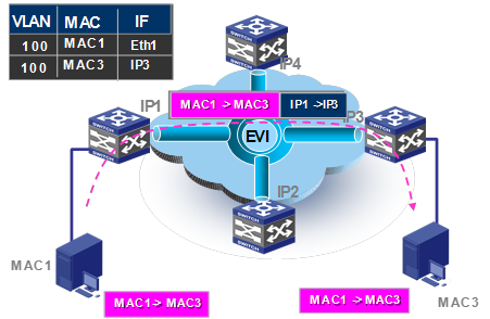
For inter-site Layer 2 communication, the following forwarding process (see Figure 9) takes place:
1. The source edge device learns the source MAC address of the incoming Ethernet frame, and looks up the destination MAC address in its MAC table for the outgoing interface.
2. If the outgoing interface is an EVI tunnel interface rather than a physical port, the source edge device encapsulates the frame in a GRE header before adding an IP header and a link layer protocol header.
In the outer IP header, the source IP address is the IP address of the EVI-Connect interface, and the destination IP address is the remote edge device's IP address.
3. The source edge device forwards the encapsulated packet out of the EVI-Connect interface to the destination edge device across the IP transport network.
4. At the destination site, the destination edge device removes the headers of the Ethernet frame, looks up the destination MAC address in the MAC address table, and sends the frame out of the matching outgoing interface to the destination host.
Figure 9 Inter-site Layer 2 traffic
Multicast traffic
Edge devices run a multicast snooping protocol on each extended VLAN and learn multicast router port and multicast member port information on EVI-Link interfaces as if they were Ethernet interfaces. In an extended VLAN, the control plane of each edge device tunnels IGMP, MLD, and PIM protocol packets to all its remote edge devices, and the remote edge devices flood the packets in the VLAN.
Figure 10 shows the inter-site IGMP group-specific query process.
Figure 10 Inter-site group-specific query process
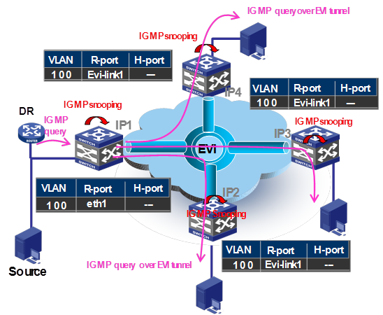
1. The DR in site IP 1 sends a group-specific query in VLAN 100.
2. The site edge device snoops the query, and learns the multicast address and router port eth1 in VLAN 100.
3. The edge device copies the query and encapsulates one copy on each multicast member EVI-Link interface, and unicasts the encapsulated frames to the destination edge devices over the EVI links.
4. Each destination edge device decapsulates the frame, and creates a multicast entry with the EVI-Link interface (EVI-Link 1 in this example) as the router port.
5. Each destination edge device sends the multicast frame out of all group member interfaces in VLAN 100 to the destination hosts.
Figure 11 shows the inter-site IGMP group-specific join process.
Figure 11 Inter-site group-specific join process
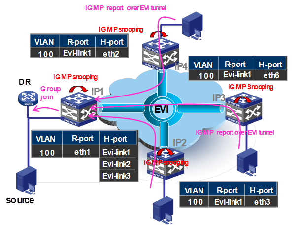
1. A multicast group member in site IP 3 sends a group-specific report.
2. The IP 3 edge device snoops the message and learns the host port eth2, eth3, and eth6.
3. The IP 3 edge device encapsulates the message on the router port EVI-Link 1 in a unicast frame, and sends the frame over EVI link 1 to the IP 1 edge device on the multicast source side.
4. The IP 1 edge device decapsulates the frame and learns the host port EVI-Link 1, EVI-Link 2, and EVI-Link 3.
5. The IP 1 edge device sends the report out of the router port eth1 to the DR, where the VLAN-interface 100 is set as the router port.
Figure 12 shows the inter-site multicast data frame forwarding process.
Figure 12 Multicast data frame forwarding process
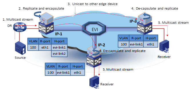
1. The DR in site IP 1 sends out a multicast frame.
2. The IP 1 edge device copies the frame and encapsulates one copy on each multicast member EVI-Link interface.
3. The IP 1 edge device unicasts the encapsulated frames to the destination edge devices over the EVI links.
4. Each destination edge device removes the headers of the multicast frame and copies the multicast frame on each multicast member interface.
5. Each destination edge device sends the multicast frame out of all member interfaces to the destination hosts.
Broadcast flow and traffic flooding
An EVI edge device handles floodings by frame type, as follows:
Broadcast frame—Floods the frame to all interfaces in the VLAN where the frame has been received, including internal interfaces and EVI-Link interfaces. For ARP packets, you can use the ARP flood suppression feature (see "ARP flood suppression") to reduce ARP broadcasts. Up to the date of this writing, Comware only supports head-end replication. An EVI edge device must replicate broadcast frames, encapsulate them in unicast frames, and send the unicast frames to all remote edge devices.
Destination-unknown unicast or multicast frame—Floods the frame to all internal interfaces in the VLAN where the frame has been received. The edge device typically does not propagate destination unknown frames to other sites. If a site-to-site flooding is desirable for some special MAC addresses, use the selective flood feature (see "Selective flood").
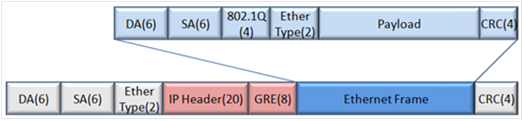
Tunnel encapsulation format
To send a frame (for example, an Ethernet frame) to a remote site, an EVI edge device encapsulates the frame intact in GRE, and then adds an outer IP header, a link layer header, and checksum information. In the outer IP header, the edge device sets the DF bit. For an Ethernet transport network, the data frame size increases by 38 bytes, and the EVI protocol frame size increases by 46 bytes.
NOTE: EVI does not support path MTU discovery. Your EVI deployment must make sure the path MTU of the transport network is higher than the maximum size of EVI tunneled frames. |
Figure 13 EVI tunnel encapsulation
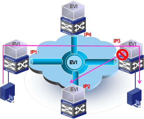
Split horizon
EVI by default implements split horizon to prevent loops among edge devices. This feature prevents frames received from EVI tunnels from being forwarded back to the transport.
Figure 14 Split horizon
Failure isolation
Layer 2 networks are broadcast intensive. To prevent a broadcast storm or topology change in one site from affecting other sites, EVI provides various failure isolation features, including spanning tree isolation, unknown frame isolation, ARP flood suppression, and broadcast suppression. These features ensure the resiliency, stability, and scalability of multi-site applications in an extended Layer 2 network.
Spanning tree isolation
By default, no spanning tree protocol runs on EVI links. Each site is a separate spanning tree domain. The edge devices do not forward spanning tree BPDUs to the transport network. Spanning tree configuration or topology changes are restricted to each site.
Figure 15 Spanning tree isolation
The lack of spanning tree protocols on edge devices can create loops across sites when redundant edge devices are deployed at a site. To avoid this issue, the edge devices at each site must run EVI IS-IS between them to negotiate a unique forwarding path for each extended VLAN. For more information, see "Multihoming."
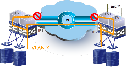
Unknown frames
EVI edge devices behave like routers when forwarding traffic on EVI-Link interfaces. By exchanging MAC reachability information through EVI IS-IS, EVI edge devices build a table of remote MAC address, outgoing EVI-Link interface, and remote site's IP address mappings for traffic forwarding. If the destination MAC address of a frame (unicast or multicast) is unknown, they flood the frame to internal interfaces, but they typically do not flood the frame to EVI-Link interfaces, as shown in Figure 16.
If a site-to-site flooding is desirable for some special MAC addresses, use the selective flood feature (see "Selective flood").
Figure 16 Unknown frames handling in EVI
Selective flood
Some data center applications use special destination MAC addresses that cannot be used as source MAC addresses to identify their traffic streams. Edge devices cannot advertise these MAC addresses through EVI IS-IS. To make sure these applications can traverse across an EVI network, configure the EVI tunnel interface to flood traffic destined for their MAC addresses to all EVI links in the tunnel.
For example, Microsoft NLBS uses a special MAC address to identify each cluster. Traffic streams destined for a cluster MAC address are forwarded to all the cluster member hosts. If the cluster member hosts are located in multiple sites, you must configure the EVI tunnel interface to advertise the cluster MAC address.
Figure 17 Selective flood
ARP flood suppression
ARP flood suppression reduces ARP request broadcasts on the EVI network by enabling edge devices to reply to ARP requests on behalf of remote-site hosts. As shown in Figure 18, this feature snoops ARP replies on an EVI tunnel interface to cache ARP entries for remote MAC addresses. If an ARP request has a matching ARP entry, the local edge device replies to the request on behalf of the remote-site host. If no matching ARP entry is found, the edge device floods the request to the EVI network.
ARP flood suppression uses the following workflow:
1. Host B sends an ARP request for Host A's MAC address.
2. Its edge device (IP 3) floods the ARP request to all ports, including EVI tunnel interfaces.
The remote edge devices (IP 1 and IP 2) decapsulate the ARP request and broadcast the request in their respective sites.
3. Host A responds to the request.
4. IP 3 creates an ARP cache entry for Host A and forwards the reply to Host B.
5. IP 3 receives a new ARP request for Host A's MAC address.
6. IP 3 looks through its ARP cache and responds on behalf of Host A.
Figure 18 ARP flood suppression
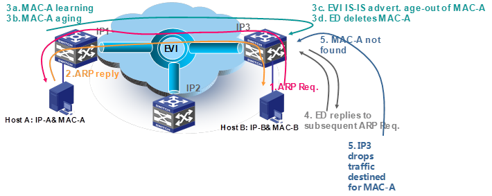
To avoid traffic blackholes, make sure the lifetime of a remote MAC address entry in a MAC address table is longer than the EVI ARP entry aging timer (fixed at 15 minutes). The lifetime of a remote MAC address entry is determined by the MAC address aging timer and the LSP refresh interval set on the edge device that has advertised the MAC address.
If the lifetime of a remote MAC address is shorter than the EVI ARP entry aging timer, traffic blackholes might occur, as shown in Figure 19.
The following is the process for a traffic blackhole to occur:
1. Host B sends s an ARP request for Host A's MAC address.
2. Host A replies with its MAC address (MAC-A).
3. IP 1 learns MAC-A to the MAC address table and starts an aging timer.
IP 3 creates an ARP cache entry for the remote MAC address and forwards the reply to Host B.
IP 3 also starts an aging timer for the ARP cache entry. The MAC address aging timer is shorter than the ARP cache entry timer.
4. After MAC-A ages out in IP 1's MAC address table, IP 1 sends an EVI IS-IS LSP update to instruct the remote edge devices (including IP 3) to delete MAC-A.
5. All the LSP receiving edge devices, including IP 3, delete MAC-A from their MAC address tables. However, IP 3 still replies to subsequent ARP requests for MAC-A because the ARP entry has not aged out yet.
6. When a packet destined for MAC-A arrives, IP 3 floods the packet to all internal interfaces, because the MAC-A entry has been removed and the destination is unknown. The packet can never reach the destination because MAC-A is not in site IP 3.
Figure 19 Traffic blackholes with EVI ARP caching
Multihoming
EVI supports deploying two or more EVI edge devices to provide Layer 2 connectivity extension for a site. Deployment of redundant edge devices creates the risk of loops (see Figure 20) because EVI edge devices do not transmit spanning tree BPDUs across the transport network.
Figure 20 Looped dual-homed EVI network
To remove loops in a multihomed network, you can use IRF to virtualize multiple edge devices into one device, as shown in Figure 21. If IRF is not used, EVI IS-IS runs among the redundant edge devices to automatically designate each edge device as the traffic forwarder for a particular set of extended VLANs, as shown in Figure 22.
This traffic forwarder designation mechanism makes sure an extended VLAN is active only on one edge device so the EVI network is single-homed on a per-VLAN basis.
Figure 21 Edge devices in an IRF fabric
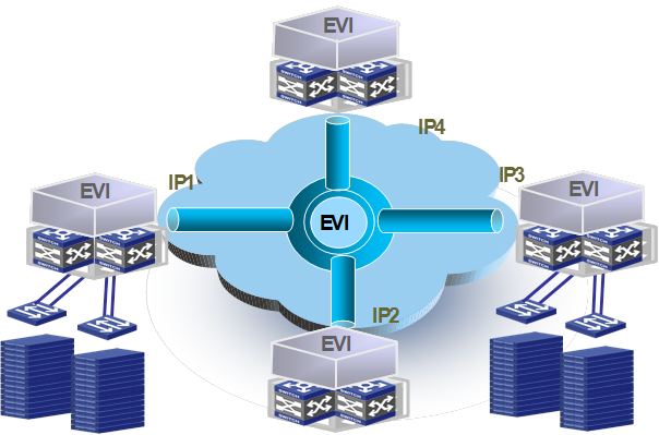
Figure 22 Active VLAN on an edge device
The appointed edge forwarder for an extended VLAN performs the following tasks:
Controls access of the VLAN to the EVI tunnel.
Forwards and receives traffic between sites over the transport network for the VLAN.
Snoops IGMP, MLD, or MRD packets in extended VLANs on EVI-Link interfaces to learn multicast group members and router port information.
Advertises MAC reachability information in the VLAN to remote edge devices.
The redundant edge devices exchange EVI IS-IS hello packets in a designated site VLAN to elect a DED for exchanging extended VLAN information and assigning active VLANs among them. All edge devices have a user-configurable DED priority. The one with the highest DED priority is elected as the DED. The DED uses the following rules to assign active VLANs:
1. If an extended VLAN is configured only on one edge device, the edge device is the appointed edge forwarder for the VLAN.
2. If a set of extended VLANs is configured on at least two edge devices, the DED distributes the extended VLANs equally among the edge devices.
3. When reassigning VLANs, the DED preferably assigns an edge device the active VLANs that were assigned to it in the previous assignment.
The site VLAN must not be an extended VLAN.
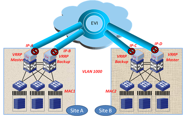
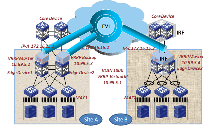
Placement of Layer 3 gateway
An edge device by default does not flood unknown multicast packets (including VRRP packets) to other sites. For the hosts in a site, their Layer 3 gateway is located on the local edge device. As shown in Figure 23, VLAN 1000 has one Layer 3 gateway on each site.
To deploy one gateway for several sites in an EVI network, configure selective flood for the virtual MAC addresses in VRRP so VRRP packets can be exchanged between sites.
Figure 23 Placement of Layer 3 gateways in an EVI network
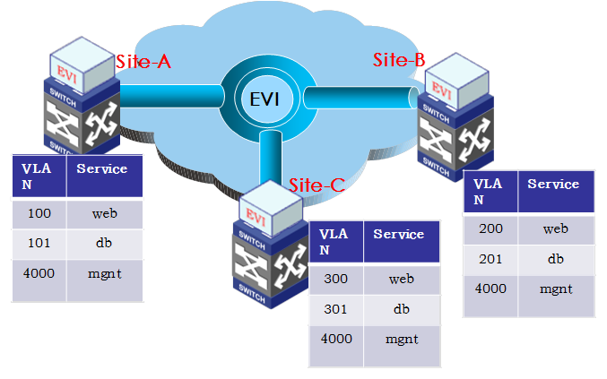
VLAN mapping
If the VLAN assignment scheme is not consistent across the sites, deploy VLAN mapping on the edge devices to map different VLANs for the same type of traffic to each other. VLAN mapping enables inter-VLAN communication by swapping VLAN tags. It does not require changes to the existing VLAN assignment scheme at a site.
For example, the sites in Figure 24 use different VLANs for the Web service. To enable the communication of Web service between Site-A and Site-B, map VLAN 100 to VLAN 200 on the Site-A edge device, and map VLAN 200 to VLAN 100 on the Site-B edge device.
When configuring VLAN mappings, make sure the mappings are symmetric between the peer sites.
Technical specifications
Use this section as an EVI deployment reference. The specifications are limitations in software and are subject to change without notice. For the latest EVI technical specifications, contact your H3C representatives.
Item | Specification |
EVI networks (VPNs) | 32 |
Total number of edge devices/EVI network | 64 |
Edge devices/EVI network at each site | 2 (You can set up a 4-chassis IRF fabric as the edge device for a site.) |
Extended VLANs | 4K |
Unicast MAC address entries/LSP | 128K (This specification might vary by devices.) |
Maximum number of MAC addresses configured for selective flood | 1000 (This specification might vary by devices.) |
Deployment reference models
EVI deployment depends on the data center topology design.
Most data centers use layered hierarchical design. Typically, nodes are deployed with redundancy at each layer. At the aggregation layer, service processing devices or modules (such as SLBs, firewalls, and IPSs) are deployed also with redundancy. The aggregation devices form the boundaries between Layer 2 broadcast domain and Layer 3 routed network.
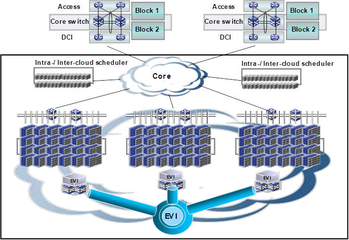
For high availability and dynamic resources management, enterprises typically apply the same network design to their dispersed data centers, and deploy the same applications across the data centers. A practice that has been widely used is to deploy modular data centers, such as HP PODs. Each modular data center (or POD) includes a set of servers, racks, access switches, and aggregation switches. Data center expansion is to add PODs as needed. The PODs are connected through core layer devices.
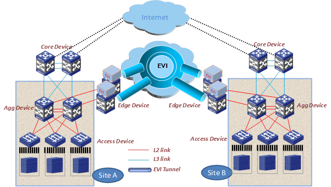
Figure 25 shows a generic EVI deployment model for data centers. In this model, one or more edge devices are deployed at each data center site for site-to-site Layer 2 connectivity. The PODs are connected to their respective edge devices through Layer 2 links, forming a large Layer 2 domain.
Figure 25 Generic EVI deployment model for data centers
Data center core layer
The core layer of a data center typically comprises two highly reliable high-performance chassis for node redundancy. In large or geographically distributed data centers, more chassis might be deployed at this layer. These chassis provide reliable high-performance Layer 3 switching services for traffic from various sources such as campuses, Internet edges, WANs, and branches. To minimize the impact of broadcast traffic, point-to-point Layer 3 connections are typically deployed between the core layer and the aggregation layer.
In the generic EVI deployment model, deploy EVI edge devices on top of the core layer devices so intra-site Layer 2 traffic shares the same egress as Layer 3 traffic at each site, as shown in Figure 26.
Figure 26 Deploying EVI at the data center core layer
In this EVI deployment model, the aggregation devices must have layer 2 links to the core devices for extended VLANs, in addition to Layer 3 connections.
This model extends the spanning tree domains of extended VLANs to the core layer, even though the aggregation layer is still the Layer 2/Layer 3 boundary within each site. Topology changes in an extended VLAN can affect the core layer.
To prevent traffic floods in extended VLANs from using the bandwidth designed for inter-VLAN traffic, the Layer 2 links and the Layer 3 links between the aggregation layer and the core layer must be separated physically.
To decreases topology complexity while removing Layer 2 loops, deploy IRF and link aggregation at the core Layer and the aggregation layer.
Data center aggregation layer
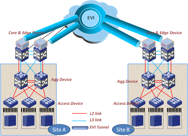
Small data centers typically do not have the core layer, and their aggregation layer is directly connected to the core devices of the enterprise network.
The aggregation layer is the Layer 2 and Layer 3 network boundary. In a small data center, you can deploy EVI on the aggregation devices to provide Layer 2 connectivity extension to remote data centers. The aggregation devices and the access devices run a spanning tree protocol or IRF to eliminate loops.
See Figure 27. Site A is dual-homed to the core network and runs a spanning tree protocol to eliminate loops. Site B is also dual-homed to the core network, but it runs IRF to change the logical topology to a singled-homed network.
Figure 27 Deploying EVI at the data center aggregation layer
To distribute Layer 2 and Layer 3 traffic of extended VLANs between redundant EVI edge devices in a spanning tree domain, use the MSTP multi-instance and EVI dual-homing features.
Configure the appointed edge forwarder for an extended VLAN as both the root bridge in the spanning tree instance for the VLAN and the VRRP master. This configuration makes sure that the Layer 2 and Layer 3 traffic of an extended VLAN always traverse the same EVI edge device, while traffic of different extended VLANs is load balanced between the EVI edge devices, as shown in Figure 28.
Figure 28 Deploying load-balancing in an STP-based site for extended VLANs

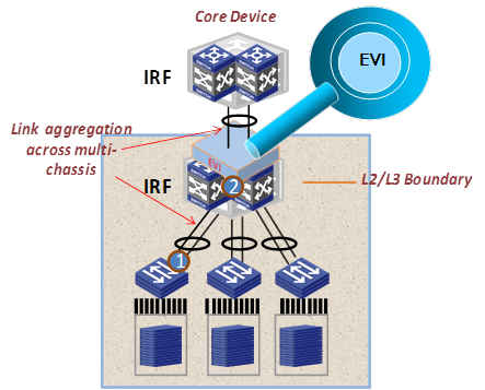
To distribute Layer 2 and Layer 3 traffic of extended VLANs between redundant EVI edge devices in an IRF fabric, use the multichassis link aggregation feature.
As shown in Figure 29, the IRF fabric is connected through multichassis link aggregation to the access devices and the core network. Traffic is automatically distributed between the EVI edge devices in the IRF fabric.
Figure 29 Deploying load-balancing in an IRF-based site for extended VLANs
To avoid incorrect cabling or configuration causing loops, it's a good practice to configure the spanning tree feature on each IRF member device as a backup to IRF. If the cabling and configuration are correct, no false link blocking will occur.
Application scenarios
This section provides several typical application scenarios.
Deploying EVI at the data center aggregation layer
Site A and Site B each have two aggregation devices connected to the IP core network, as shown in Figure 30.
The aggregation devices run EVI to provide site-to-site Layer 2 connectivity across the IP core network for some VLANs, and they also provide gateway services for these VLANs in their respective sites.
To remove loops, Site A's aggregation devices run the spanning tree feature and Site B's aggregation devices run IRF.
Figure 30 Deploying EVI at the data center aggregation layer
Configuration procedure summary
To configure an EVI edge device:
1. Configure IRF. Skip this step if the spanning tree feature is used.
2. Configure features for site-facing interfaces, including VLANs, spanning tree feature, link aggregation, multicast snooping.
3. Configure features for transport-facing interfaces, including IP addressing and routing.
4. Configure the EVI feature, including EVI tunnel interfaces, EVI IS-IS, ENDP, and ARP flood suppression.
Deploying multiple EVI networks
Deploy multiple EVI networks to extend VLANs for different network services. These EVI networks can span different sets of sites.
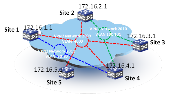
In Figure 31, three EVI networks are deployed. EVI network 2009 extends VLAN 4000 across all sites for management traffic; EVI network 2011 extends VLANs 50 to 80 among Site 2, Site 3, and Site 4 for Web access traffic; and EVI network 2010 extends VLANs 100 and 101 among Site 1, Site 3, Site 4, and Site 5 for database traffic. Site 4's edge device is the ENDS in all EVI networks.
Figure 31 Deploying multiple EVI networks