This document provides IPv6 over IPv4
tunneling configuration examples.
IPv6 over IPv4 tunneling adds an IPv4
header to IPv6 packets. This technology enables transmission of IPv6 packets
over an IPv4 network between isolated IPv6 networks.
The configuration examples in this document
were created and verified in a lab environment, and all the devices were started
with the factory default configuration. When you are working on a live network,
make sure you understand the potential impact of every command on your network.
This document assumes that you have basic
knowledge of IPv6 over IPv4 tunneling.
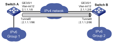
As shown in Figure
1, dual-stack switches Switch A and Switch B can reach each other through
IPv4.
Configure an automatic IPv4-compatible IPv6
tunnel between the two switches for IPv6 Group 1 and IPv6 Group 2 to
communicate over the IPv4 network.
Figure 1 Network diagram
This configuration example was created and
verified on S12500-CMW710-R7129.
When you configure an automatic
IPv4-compatible IPv6 tunnel, follow these restrictions and guidelines:
· The source interface for the tunnel must be up and must have an IP address. It
can be a VLAN interface, a GigabitEthernet interface, or a loopback interface.
· Configure the same tunnel mode at both ends of the tunnel.
· Configure the IPv4-compatible IPv6 address in
the format of ::IPv4-source-address/96.
· You do not need to configure the destination
IPv4 address of the tunnel. The destination IPv4 address is embedded in the IPv4-compatible
IPv6 address.
# Create VLAN 12, and assign
GigabitEthernet 3/0/1 to it.
<Switch-A> system-view
[Switch-A] vlan 12
[Switch-A-vlan12] port
GigabitEthernet 3/0/1
[Switch-A-vlan12] quit
# Create VLAN-interface 12, specify its IP
address, and bring it up.
[Switch-A] interface Vlan-interface
12
[Switch-A-Vlan-interface12] ip
address 2.1.1.1 8
[Switch-A-Vlan-interface12] undo
shutdown
[Switch-A-Vlan-interface12] quit
# Bring up GigabitEthernet
3/0/1.
[SwitchA] interface GigabitEthernet 3/0/1
[SwitchA-GigabitEthernet3/0/1] undo
shutdown
[SwitchA-GigabitEthernet3/0/1] quit
# Create an automatic IPv4-compatible IPv6
tunnel.
[Switch-A] interface Tunnel 0 mode
ipv6-ipv4 auto-tunnel
# Specify an IPv4-compatible IPv6 address
for the tunnel interface.
[Switch-A-Tunnel0] ipv6 address
::2.1.1.1 96
# Specify VLAN-interface 12 as the source
interface of the tunnel.
[Switch-A-Tunnel0] source
Vlan-interface 12
[Switch-A-Tunnel0] quit
# Create VLAN 12, and assign
GigabitEthernet 3/0/1 to it.
<Switch-B> system-view
[Switch-B] vlan 12
[Switch-B-vlan12] port
GigabitEthernet 3/0/1
[Switch-B-vlan12] quit
# Create VLAN-interface 12, specify its IP
address, and bring it up.
[Switch-B] interface Vlan-interface
12
[Switch-B-Vlan-interface12] ip
address 2.1.1.2 8
[Switch-B-Vlan-interface12] undo
shutdown
[Switch-B-Vlan-interface12] quit
# Bring up GigabitEthernet
3/0/1.
[SwitchB] interface GigabitEthernet 3/0/1
[SwitchB-GigabitEthernet3/0/1] undo
shutdown
[SwitchB-GigabitEthernet3/0/1] quit
# Create an automatic IPv4-compatible IPv6 tunnel.
[SwitchB] interface tunnel 0 mode ipv6-ipv4
auto-tunnel
# Specify an IPv4-compatible IPv6 address
for the tunnel interface.
[SwitchB-Tunnel0] ipv6 address ::2.1.1.2/96
# Specify VLAN-interface 12 as the source
interface of the tunnel.
[SwitchB-Tunnel0] source vlan-interface 12
[SwitchB-Tunnel0] quit
Verify that Switch A and Switch B can ping
the IPv4-compatible IPv6 address of each other.
# Ping the IPv4-compatible IPv6 address of
Switch B from Switch A.
<SwitchA> ping ipv6 -a ::2.1.1.1
::2.1.1.2
PING :: 2.1.1.2 : 56 data bytes,
press CTRL_C to break
Reply from :: 2.1.1.2
bytes=56 Sequence=1 hop limit=64
time = 2 ms
Reply from :: 2.1.1.2
bytes=56 Sequence=2 hop limit=64
time = 4 ms
Reply from :: 2.1.1.2
bytes=56 Sequence=3 hop limit=64
time = 3 ms
Reply from :: 2.1.1.2
bytes=56 Sequence=4 hop limit=64
time = 2 ms
Reply from :: 2.1.1.2
bytes=56 Sequence=5 hop limit=64
time = 3 ms
--- :: 2.1.1.2 ping statistics ---
5 packet(s) transmitted
5 packet(s) received
0.00% packet loss
round-trip min/avg/max = 2/2/4 ms
# Ping the IPv4-compatible IPv6 address of
Switch A from Switch B.
<SwitchB> ping ipv6 -a ::2.1.1.2
::2.1.1.1
PING :: 2.1.1.1 : 56 data bytes,
press CTRL_C to break
Reply from :: 2.1.1.1
bytes=56 Sequence=1 hop limit=64
time = 2 ms
Reply from :: 2.1.1.1
bytes=56 Sequence=2 hop limit=64 time
= 4 ms
Reply from :: 2.1.1.1
bytes=56 Sequence=3 hop limit=64
time = 3 ms
Reply from :: 2.1.1.1
bytes=56 Sequence=4 hop limit=64
time = 2 ms
Reply from :: 2.1.1.1
bytes=56 Sequence=5 hop limit=64
time = 3 ms
--- :: 2.1.1.1 ping statistics ---
5 packet(s) transmitted
5 packet(s) received
0.00% packet loss
round-trip min/avg/max = 2/2/4 ms
· Switch A:
#
vlan 12
#
interface Vlan-interface12
ip address 2.1.1.1 255.0.0.0
#
interface GigabitEthernet3/0/1
port link-mode bridge
port access vlan 12
#
interface Tunnel0 mode
ipv6-ipv4 auto-tunnel
ipv6 address ::2.1.1.1/96
source Vlan-interface12
#
· Switch B:
#
vlan 12
#
interface Vlan-interface12
ip address 2.1.1.2 255.0.0.0
#
interface GigabitEthernet3/0/1
port link-mode bridge
port access vlan 12
#
interface Tunnel0 mode
ipv6-ipv4 auto-tunnel
ipv6 address ::2.1.1.2/96
source Vlan-interface12
#
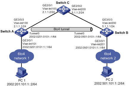
As shown in Figure
2, configure a 6to4 tunnel between 6to4 switches
Switch A and Switch B for PC 1 and PC 2 to communicate over the IPv4 network.
Figure 2 Network diagram
For packets between the two PCs to be
forwarded over the 6to4 tunnel, configure a static route (dynamic routing not
supported) on Switch A and Switch B as follows:
· Specify the IPv6 address of the remote PC as the
destination address of the route.
· Specify the local tunnel interface as the output
interface of the route, or specify the peer tunnel interface as the next hop of
the route.
To make sure the tunnel source and the
tunnel destination can reach each other, configure a static route to the tunnel
destination on both Switch A and Switch B. The next hop for the two routes is
Switch C.
This configuration example was created and
verified on S12500-CMW710-R7129.
When you configure a 6to4 tunnel, follow
these restrictions and guidelines:
· The source interface for the tunnel must be up and must have an IP address. It
can be a VLAN interface, a GigabitEthernet interface, or a loopback interface.
· Configure the same tunnel mode at both ends of the tunnel.
· Configure the 6to4
address in the format of 2002:IPv4-source-address::/48.
· The embedded IPv4 address in an IPv6 address of
a 6to4 tunnel must not be a private IP address.
· You do not need to configure the destination
IPv4 address of the tunnel. The destination IPv4 address is embedded in the
6to4 IPv6 address.
# Create VLAN 100, and assign
GigabitEthernet 3/0/3 to it.
<SwitchA> system-view
[SwitchA] vlan 100
[SwitchA-vlan100] port
GigabitEthernet 3/0/3
[SwitchA-vlan100] quit
# Create VLAN-interface 100, specify its IP
address, and bring it up.
[SwitchA] interface Vlan-interface 100
[SwitchA-Vlan-interface100] ip
address 2.1.1.1 255.255.255.0
[SwitchA-Vlan-interface100] undo
shutdown
[SwitchA-Vlan-interface100] quit
# Bring up GigabitEthernet
3/0/3.
[SwitchA] interface GigabitEthernet 3/0/3
[SwitchA-GigabitEthernet3/0/3] undo
shutdown
[SwitchA-GigabitEthernet3/0/3] quit
# Create VLAN 101, and assign
GigabitEthernet 3/0/1 to it.
[SwitchA] vlan 101
[SwitchA-vlan101] port
GigabitEthernet 3/0/1
[SwitchA-vlan101] quit
# Create VLAN-interface 101, specify its IP
address, and bring it up.
|
|
NOTE:
The IPv4 address of VLAN-interface 100 is
2.1.1.1/24, which uses the
6to4 prefix 2002:0201:0101::/48. Specify the 6to4
address of VLAN-interface 101 from a subnet of the 6to4 prefix. This example uses subnet 2002:0201:0101:1::/64.
|
[SwitchA] interface Vlan-interface
101
[SwitchA-Vlan-interface101] ipv6
address 2002:0201:0101:1::1 64
[SwitchA-Vlan-interface101] undo
shutdown
[SwitchA-Vlan-interface101] quit
# Bring up GigabitEthernet
3/0/1.
[SwitchA] interface GigabitEthernet 3/0/1
[SwitchA-GigabitEthernet3/0/1] undo
shutdown
[SwitchA-GigabitEthernet3/0/1] quit
# Create a 6to4 tunnel interface Tunnel 0.
[SwitchA] interface tunnel 0 mode ipv6-ipv4 6to4
# Specify a 6to4 address for the tunnel
interface.
|
|
NOTE:
The IPv4 address of VLAN-interface 100 is
2.1.1.1/24, which uses the
6to4 prefix 2002:0201:0101::/48. Specify the 6to4
address of the tunnel interface from a subnet of the 6to4 prefix. This example uses subnet 2002:0201:0101:1::/64.
|
[SwitchA-Tunnel0] ipv6 address 2002:201:101::1/64
# Specify VLAN-interface 100 as the tunnel
source interface.
[SwitchA-Tunnel0] source
Vlan-interface 100
[SwitchA-Tunnel0]quit
# Create a static route to PC 2 through the
tunnel interface.
[SwitchA] ipv6 route-static 2002:: 16
Tunnel 0
# Create a static route to the tunnel
destination.
[SwitchA] ip route-static 5.1.1.0
255.255.255.0 2.1.1.2
# Create VLAN 200, and assign
GigabitEthernet 3/0/3 to it.
<SwitchB> system-view
[SwitchB] vlan 200
[SwitchB-vlan200] port
GigabitEthernet 3/0/3
[SwitchB-vlan200] quit
# Create VLAN-interface 200, specify its IP
address, and bring it up.
[SwitchB] interface Vlan-interface 200
[SwitchB-Vlan-interface200] ip
address 5.1.1.1 255.255.255.0
[SwitchB-Vlan-interface200] undo
shutdown
[SwitchB-Vlan-interface200] quit
# Bring up GigabitEthernet
3/0/3.
[SwitchB] interface GigabitEthernet 3/0/3
[SwitchB-GigabitEthernet3/0/3] undo
shutdown
[SwitchB-GigabitEthernet3/0/3] quit
# Create VLAN 201, and assign
GigabitEthernet 3/0/1 to it.
[SwitchB] vlan 201
[SwitchB-vlan201] port
GigabitEthernet 3/0/1
[SwitchB-vlan201] quit
# Create VLAN-interface 201, specify its IP
address, and bring it up.
|
|
NOTE:
The IPv4 address of VLAN-interface 200 is 5.1.1.1/24, which uses the 6to4 prefix 2002:0501:0101::/48. Specify
the 6to4 address of VLAN-interface 201 from a subnet of the
6to4 prefix. This example uses subnet 2002:0501:0101:1::/64.
|
[SwitchB] interface Vlan-interface 201
[SwitchB-Vlan-interface201] ipv6
address 2002:0501:0101:1::1 64
[SwitchB-Vlan-interface201] undo
shutdown
[SwitchB-Vlan-interface201] quit
# Bring up GigabitEthernet
3/0/1.
[SwitchB] interface GigabitEthernet 3/0/1
[SwitchB-GigabitEthernet3/0/1] undo
shutdown
[SwitchB-GigabitEthernet3/0/1] quit
# Create a 6to4 tunnel interface Tunnel 0.
[SwitchB] interface tunnel 0 mode ipv6-ipv4
6to4
# Specify a 6to4 address for the tunnel
interface.
|
|
NOTE:
The IPv4 address of VLAN-interface 200 is 5.1.1.1/24, which uses the 6to4 prefix 2002:0501:0101::/48. Specify
the 6to4 address of the tunnel interface from a subnet of
the 6to4 prefix. This example uses subnet 2002:0501:0101:1::/64.
|
[SwitchB-Tunnel0] ipv6 address 2002:0501:0101::1/64
# Specify VLAN-interface 200 as the tunnel
source interface.
[SwitchB-Tunnel0] source vlan-interface 200
[SwitchB-Tunnel0] quit
# Create a static route to PC 1 through the
tunnel interface.
[SwitchB] ipv6 route-static 2002:: 16
Tunnel 0
# Create a static route to the tunnel
destination.
[SwitchB] ip route-static 2.1.1.0
255.255.255.0 5.1.1.2
# Specify IP addresses for the VLAN
interfaces, as shown in Figure 2. (Details not
shown.)
The following tasks are performed on
Windows XP:
# Install the IPv6 protocol on PC 1.
C:\>ipv6 install
# Display the IPv6 interface configuration to
obtain the interface index.
C:\>ipv6 if
# Configure an IPv6 address for the
interface. Typically, the interface index is 5.
C:\>ipv6 adu 5/2002:201:101:1::2
# Configure an IPv6 default route.
C:\>ipv6 rtu ::/0
5/2002:201:101:1::1
The following tasks are performed on
Windows XP:
# Install the IPv6 protocol on PC 2.
C:\>ipv6 install
# Display the IPv6 interface configuration to
obtain the interface index.
C:\>ipv6 if
# Configure an IPv6 address for the
interface. Typically, the interface index is 5.
C:\>ipv6 adu 5/2002:501:101:1::2
# Configure an IPv6 default route.
C:\>ipv6 rtu ::/0
5/2002:501:101:1::1
Verify that PC 1 and PC 2 can ping each
other.
# Ping PC 2 from PC 1.
C:\>ping6 -s 2002:201:101:1::2
2002:501:101:1::2
Pinging 2002:501:101:1::2
from 2002:201:101:1::2 with 32 bytes
of data:
Reply from 2002:501:101:1::2:
bytes=32 time<1ms
Reply from 2002:501:101:1::2:
bytes=32 time<1ms
Reply from 2002:501:101:1::2:
bytes=32 time<1ms
Reply from 2002:501:101:1::2:
bytes=32 time<1ms
Ping statistics for 2002:501:101:1::2:
Packets: Sent = 4, Received = 4,
Lost = 0 (0% loss),
Approximate round trip times in
milli-seconds:
Minimum = 0ms, Maximum = 0ms,
Average = 0ms
# Ping PC 1 from PC 2.
C:\>ping6 -s 2002:501:101:1::2
2002:201:101:1::2
Pinging 2002:201:101:1::2
from 2002:501:101:1::2 with 32 bytes
of data:
Reply from 2002:201:101:1::2:
bytes=32 time<1ms
Reply from 2002:201:101:1::2:
bytes=32 time<1ms
Reply from 2002:201:101:1::2:
bytes=32 time<1ms
Reply from 2002:201:101:1::2:
bytes=32 time<1ms
Ping statistics for 2002:201:101:1::2:
Packets: Sent = 4, Received = 4,
Lost = 0 (0% loss),
Approximate round trip times in
milli-seconds:
Minimum = 0ms, Maximum = 0ms,
Average = 0ms
· Switch A:
#
vlan 100 to 101
#
interface Vlan-interface100
ip address 2.1.1.1 255.0.0.0
#
interface Vlan-interface101
ipv6 address
2002:201:101:1::1/64
#
interface GigabitEthernet3/0/1
port link-mode bridge
port access vlan 101
#
interface GigabitEthernet3/0/3
port link-mode bridge
port access vlan 100
#
interface Tunnel0 mode ipv6-ipv4
6to4
ipv6 address
2002:201:101::1/64
source Vlan-interface100
#
ip route-static 5.1.1.0
255.255.255.0 2.1.1.2
#
ipv6 route-static 2002:: 16
Tunnel0
#
· Switch B:
#
vlan 200 to 201
#
interface Vlan-interface200
ip address 5.1.1.1 255.0.0.0
#
interface Vlan-interface201
ipv6 address
2002:501:101:1::1/64
#
interface GigabitEthernet3/0/1
port link-mode bridge
port access vlan 201
#
interface GigabitEthernet3/0/3
port link-mode bridge
port access vlan 200
#
interface Tunnel0 mode
ipv6-ipv4 6to4
ipv6 address
2002:501:101::1/64
source Vlan-interface200
#
ip route-static 2.1.1.0
255.255.255.0 5.1.1.2
#
ipv6 route-static 2002:: 16
Tunnel0
#
· Switch C:
#
vlan 100
#
vlan 200
#
interface Vlan-interface100
ip address 2.1.1.2
255.255.255.0
#
interface Vlan-interface200
ip address 5.1.1.2 255.255.255.0
#
interface GigabitEthernet2/0/1
port link-mode bridge
port access vlan 100
#
interface GigabitEthernet2/0/2
port link-mode bridge
port access vlan 200
#
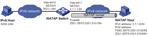
As shown in Figure
3, configure an ISATAP tunnel between the ISATAP switch and the ISATAP host
for the ISATAP host in the IPv4 network to communicate with the IPv6 host.
Figure 3 Network diagram
To make sure the ISATAP tunnel interfaces
at both ends are in the same subnet, configure the ISATAP host to generate an
IPv6 global unicast address based on the address prefix in an RA message.
To make sure the ISATAP host can receive RA
messages from the ISATAP switch, disable RA suppression on the tunnel interface
of the ISATAP switch. By default, RA suppression is enabled.
For packets between the ISATAP host and the
IPv6 host to be forwarded through the ISATAP tunnel, configure a static route to
the destination IPv6 network at each tunnel end. You can specify the local
tunnel interface as the output interface of the route, or specify the IPv6
address of the peer tunnel interface as the next hop of the route. (Dynamic
routing not supported.)
This configuration example was created and
verified on S12500-CMW710-R7129.
When you configure an ISATAP tunnel, follow
these restrictions and guidelines:
· The source interface for the tunnel must be up and must have an IP address. It
can be a VLAN interface, a GigabitEthernet interface, or a loopback interface.
· Configure the same tunnel mode at both ends of the
tunnel.
· Configure the ISATAP address in the format of Prefix:0:5EFE:IPv4-source-address/64.
· You do not need to configure the destination
IPv4 address of the tunnel, because the destination IPv4 address is embedded in the ISATAP address.
· By default, Ethernet, VLAN, and aggregate
interfaces are shut down. You must use the undo shutdown command to bring them
up.
# Specify IP addresses for the VLAN
interfaces, as shown in Figure 3. (Details not
shown.)
# Create an ISATAP tunnel interface Tunnel
0.
[Switch] interface tunnel 0 mode ipv6-ipv4 isatap
# Specify an ISATAP address for the tunnel
interface.
[Switch-Tunnel0] ipv6 address 2001::5efe:0201:0101 64
# Specify VLAN-interface 11 as the tunnel
source interface.
[Switch-Tunnel0] source vlan-interface 11
# Disable the RA suppression.
[Switch-Tunnel0] undo ipv6 nd ra halt
[Switch-Tunnel0] quit
# Configure a static route to the ISATAP
host through the tunnel interface.
[Switch] ipv6 route-static 2001:: 16
tunnel 0
The following tasks are performed on
Windows XP:
# Install the IPv6 protocol on the ISATAP
host.
C:\>ipv6 install
# Display the IPv6 interface configuration to
obtain the index of the ISATAP tunnel interface.
C:\>ipv6 if
# Configure the destination IPv4 address of
the ISATAP tunnel. Typically, the interface index is 2.
C:\>ipv6 rlu 2 2.1.1.1
# Configure a static route.
C:\>ipv6 rtu 3000::/64
2/2001::5efe:2.1.1.1
# Display information about the ISATAP
interface.
C:\>ipv6 if 2
Interface 2: Automatic Tunneling
Pseudo-Interface
Guid
{48FCE3FC-EC30-E50E-F1A7-71172AEEE3AE}
does not use Neighbor Discovery
uses Router Discovery
routing preference 1
EUI-64 embedded IPv4 address: 2.1.1.2
router link-layer address: 2.1.1.1
preferred global 2001::5efe:2.1.1.2,
life 29d23h59m46s/6d23h59m46s (public)
preferred link-local fe80::5efe:2.1.1.2,
life infinite
link MTU 1500 (true link MTU 65515)
current hop limit 255
reachable time 42500ms (base
30000ms)
retransmission interval 1000ms
DAD transmits 0
default site prefix length 48
The following tasks are performed on
Windows XP:
# Install the IPv6 protocol on the IPv6
host.
C:\>ipv6 install
# Display the IPv6 interface configuration to
obtain the interface index.
C:\>ipv6 if
# Configure an IPv6 address for the
interface. Typically, the interface index is 4.
C:\>ipv6 adu 4/3000::2
# Configure an IPv6 default route.
C:\>ipv6 rtu ::/0 4/3000::1
Verify that the IPv6 host and ISATAP host can
reach each other.
# Ping the ISATAP host from the IPv6 host.
C:\>ping6 -s 3000::2 2001::5efe:0201:0102
Pinging 2001::5efe:0201:0102
from 3000::2 with 32 bytes of data:
Reply from 2001::5efe:0201:0102:
bytes=32 time<1ms
Reply from 2001::5efe:0201:0102:
bytes=32 time<1ms
Reply from 2001::5efe:0201:0102:
bytes=32 time<1ms
Reply from 2001::5efe:0201:0102:
bytes=32 time<1ms
Ping statistics for 2001::5efe:0201:0102:
Packets: Sent = 4, Received = 4,
Lost = 0 (0% loss),
Approximate round trip times in
milli-seconds:
Minimum = 0ms, Maximum = 0ms,
Average = 0ms
# Ping the IPv6 host from the ISATAP host.
C:\>ping6 -s 2001::5efe:0201:0102
3000::2
Pinging 3000::2
from 2001::5efe:0201:0102 with 32
bytes of data:
Reply from 3000::2: bytes=32
time<1ms
Reply from 3000::2: bytes=32
time<1ms
Reply from 3000::2: bytes=32
time<1ms
Reply from 3000::2: bytes=32
time<1ms
Ping statistics for 3000::2:
Packets: Sent = 4, Received = 4,
Lost = 0 (0% loss),
Approximate round trip times in
milli-seconds:
Minimum = 0ms, Maximum = 0ms,
Average = 0ms
#
vlan 10 to 11
#
interface Vlan-interface10
ipv6 address 3000::1/64
#
#
interface Vlan-interface11
ip address 2.1.1.1 255.255.255.0
#
interface GigabitEthernet3/0/1
port link-mode bridge
port access vlan 11
#
interface GigabitEthernet3/0/3
port link-mode bridge
port access vlan 10
#
interface Tunnel0 mode ipv6-ipv4
isatap
ipv6 address 2001::5EFE:201:101/64
undo ipv6 nd ra halt
source Vlan-interface11
#
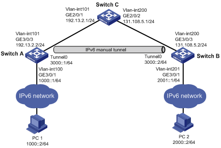
As shown in Figure
4, configure an IPv6 over IPv4 manual tunnel between Switch A and Switch B for
the two IPv6 networks to communicate with each other.
Figure 4 Network diagram
For packets between PC 1 and PC 2 to be
forwarded through the IPv6 over IPv4 manual tunnel, configure a static route or
a dynamic route on both Switch A and Switch B.
· To configure a static route:
¡ Specify the IPv6 address of the destination PC as the route destination
address.
¡ Specify the local tunnel interface as the output interface of the
route, or specify the peer tunnel interface address as the next hop of the
route.
· To configure dynamic routing, enable a dynamic
routing protocol on the tunnel interface and the VLAN
interface that connects to the PC.
To make sure the tunnel source and the
tunnel destination can reach each other, configure a static route to the tunnel
destination on both Switch A and Switch B. The next hop for the two routes is
Switch C.
This configuration example was created and
verified on S12500-CMW710-R7129.
When you configure an IPv6 overt IPv4
manual tunnel, follow these restrictions and guidelines:
· The source interface for the tunnel must be up and must have an IP address. It
can be a VLAN interface, a GigabitEthernet interface, or a loopback interface.
· Configure the same tunnel mode at both ends of the tunnel.
· The tunnel destination address specified on the
local device must be identical with the tunnel source address specified on the
tunnel peer device.
· By default, Ethernet, VLAN, and aggregate
interfaces are shut down. You must use the undo shutdown command to bring them
up.
# Specify IP addresses for the VLAN
interfaces, as shown in Figure 4. (Details not
shown.)
# Create an IPv6 over IPv4 tunnel interface
Tunnel 0.
[SwitchA] interface tunnel 0 mode ipv6-ipv4
# Specify an IPv6 address for the tunnel
interface.
[SwitchA-Tunnel0] ipv6 address 3000::1/64
# Specify VLAN-interface 101 as the tunnel
source interface.
[SwitchA-Tunnel0] source vlan-interface 101
# Specify the IP address of VLAN-interface
200 on Switch B as the destination address for the tunnel interface.
[SwitchA-Tunnel0] destination 131.108.5.2
[SwitchA-Tunnel0] quit
# Configure a static route to PC 2 through
the tunnel interface.
[SwitchA] ipv6 route-static 2000:: 64
Tunnel 0
# Configure a static route to the tunnel
destination.
[SwitchA] ip route-static 131.108.5.2 255.255.255.255 192.13.2.1
# Specify IP addresses for the VLAN
interfaces, as shown in Figure 4. (Details not
shown.)
# Create an IPv6 over IPv4 tunnel interface
Tunnel 0.
[SwitchB] interface tunnel 0 mode ipv6-ipv4
# Specify an IPv6 address for the tunnel
interface.
[SwitchB-Tunnel0] ipv6 address 3000::2/64
# Specify VLAN-interface 200 as the tunnel
source interface.
[SwitchB-Tunnel0] source vlan-interface 200
# Specify the IP address of VLAN-interface
101 on Switch A as the destination address for the tunnel interface.
[SwitchB-Tunnel0] destination 192.13.2.2
[SwitchB-Tunnel0] quit
# Configure a static route to PC 1 through
the tunnel interface.
[SwitchB] ipv6 route-static 1000:: 64
Tunnel 0
# Configure a static route to the tunnel
destination.
[SwitchB] ip route-static 192.13.2.2
255.255.255.255 131.108.5.1
# Specify IP addresses for the VLAN
interfaces, as shown in Figure 4. (Details not
shown.)
The following tasks are performed on
Windows XP:
# Install the IPv6 protocol on PC 1.
C:\>ipv6 install
# Display the IPv6 interface configuration to
obtain the interface index.
C:\>ipv6 if
# Configure an IPv6 address for the
interface. Typically, the interface index is 5.
C:\>ipv6 adu 5/1000::2
# Configure an IPv6 default route.
C:\>ipv6 rtu ::/0 5/1000::1
The following tasks are performed on
Windows XP:
# Install the IPv6 protocol on PC 2.
C:\>ipv6 install
# Display the IPv6 interface configuration to
obtain the interface index.
C:\>ipv6 if
# Configure an IPv6 address for the
interface. Typically, the interface index is 5.
C:\>ipv6 adu 5/2000::2
# Configure an IPv6 default route.
C:\>ipv6 rtu ::/0 5/2000::1
Verify that PC 1 and PC 2 can reach each
other.
# Ping PC 2 from PC 1.
C:\>ping6 -s 1000::2 2000::2
Pinging 2000::2
from 1000::2 with 32 bytes of data:
Reply from 2000::2: bytes=32
time<1ms
Reply from 2000::2: bytes=32
time<1ms
Reply from 2000::2: bytes=32
time<1ms
Reply from 2000::2: bytes=32
time<1ms
Ping statistics for 2000::2:
Packets: Sent = 4, Received = 4,
Lost = 0 (0% loss),
Approximate round trip times in
milli-seconds:
Minimum = 0ms, Maximum = 0ms,
Average = 0ms
# Ping PC 1 from PC 2.
C:\>ping6 -s 2000::2 1000::2
Pinging 1000::2
from 2000::2 with 32 bytes of data:
Reply from 1000::2: bytes=32
time<1ms
Reply from 1000::2: bytes=32
time<1ms
Reply from 1000::2: bytes=32
time<1ms
Reply from 1000::2: bytes=32
time<1ms
Ping statistics for 1000::2:
Packets: Sent = 4, Received = 4,
Lost = 0 (0% loss),
Approximate round trip times in
milli-seconds:
Minimum = 0ms, Maximum = 0ms,
Average = 0ms
· Switch A:
#
vlan 100 to 101
#
interface Vlan-interface100
ipv6 address 1000::1/64
#
interface Vlan-interface101
ip address 192.13.2.2
255.255.255.0
#
interface GigabitEthernet3/0/1
port link-mode bridge
port access vlan 100
#
interface GigabitEthernet3/0/3
port link-mode bridge
port access vlan 101
#
interface Tunnel0 mode ipv6-ipv4
ipv6 address 3000::1/64
source Vlan-interface101
destination 131.108.5.2
#
ip route-static 131.108.5.2
255.255.255.255 192.13.2.1
#
ipv6 route-static 2000:: 64
Tunnel0
#
· Switch B:
#
vlan 200 to 201
#
interface Vlan-interface200
ip address 131.108.5.2 255.255.255.0
#
interface Vlan-interface201
ipv6 address 2000::1/64
#
interface GigabitEthernet3/0/1
port link-mode bridge
port access vlan 201
#
interface GigabitEthernet3/0/3
port link-mode bridge
port access vlan 200
#
interface Tunnel0 mode ipv6-ipv4
ipv6 address 3000::2/64
source Vlan-interface200
destination 192.13.2.2
#
ip route-static 192.13.2.2
255.255.255.255 131.108.5.1
#
ipv6 route-static 2000:: 64
Tunnel0
#
· Switch C:
#
vlan 101
#
vlan 200
#
interface Vlan-interface101
ip address 192.13.2.1
255.255.255.0
#
interface Vlan-interface200
ip address 131.108.5.1 255.255.255.0
#
interface GigabitEthernet2/0/1
port link-mode bridge
port access vlan 101
#
interface GigabitEthernet2/0/2
port link-mode bridge
port access vlan 200
#
· H3C S12500
Routing Switch Series Layer 3—IP Services Configuration Guide
· H3C S12500
Routing Switch Series Layer 3—IP Services Command Reference
 Login
Login
